1
Projector
CP-X10000/CP-WX11000/CP-SX12000
User's Manual (detailed) – Operating Guide
Thank you for purchasing this projector.
►Before using this product, please read the "User's Manual -
Safety Guide" and related manuals to ensure the proper use of this product.
After reading them, store them in a safe place for future reference.
WARNING
• The information in this manual is subject to change without notice.
• The manufacturer assumes no responsibility for any errors that may appear in
this manual.
• The reproduction, transfer or copy of all or any part of this document is not
permitted without express written consent.
NOTE
Trademark acknowledgment
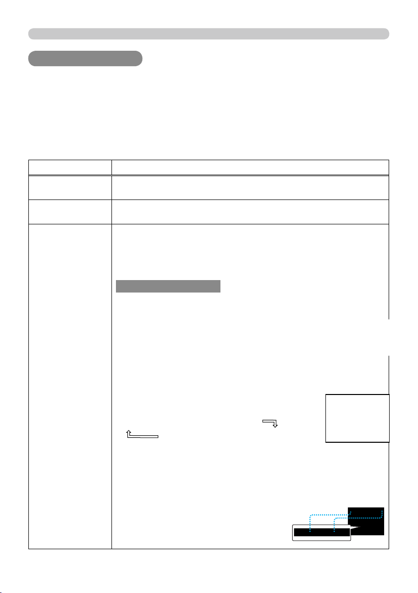
Various symbols are used in this manual. The meanings of these symbols are
described below.
About this manual
About this manual
WARNING
CAUTION
This entry warns of a risk of serious personal injury or even
death.
This entry warns of a risk of personal injury or physical damage.
Please refer to the pages written following this symbol.
• Windows
®
is a registered trademark of Microsoft Corporation in the U.S. and/or
other countries.
• VESA and DDC are trademarks of the Video Electronics Standard Association.
• Mac
®
is a registered trademark of Apple Inc.
• DVI is a trademark of Digital Display Working Group.
• HDMI, the HDMI logo and High-Defi nition Multimedia Interface are trademarks
or registered trademarks of HDMI Licensing LLC.
• Trademark PJLink is a trademark applied
for trademark rights in Japan, the United
States of America and other countries and areas.
All other trademarks are the properties of their respective owners.
NOTICE This entry notices of fear of causing trouble.
53
OPTION menu
Item Description
SERVICE
(continued)
COMMUNICATION
(continued)
DAISY CHAIN: Select this type, if it is required to
connect multiple projectors using a shared RS-232C
communication bus, from the computer. (
Network
Guide - 3.8 Multi-controlling the plural projectors (using
DAISY
CHAIN function))
OFF: Select this mode if you want to output no data
from the
CONTROL OUT
CONTROL OUT port.
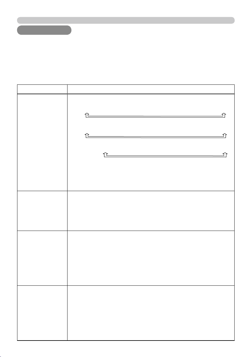
SERIAL IN SETTING/SERIAL OUT SETTING
In these menus, you can select
the communication condition for
each of the
CONTROL IN
CONTROL IN and
CONTROL OUT
CONTROL OUT ports.
BAUD RATE
4800 bps
9600 bps
38400 bps
19200 bps
PARITY
NONE
ODD
EVEN
TRANSMISSION METHOD
This menu is available only when the NETWORK
BRIDGE is selected for the COMMUNICATION TYPE.
Select the transmission method for communication by
the NETWORK BRIDGE from the
CONTROL OUT
CONTROL OUT
port.
HALF-DUPLEX
FULL-DUPLEX
HALF-DUPLEX: This method lets the projector make
two way communication, but only one direction, either
transmitting or receiving data, is allowed at a time.
FULL-DUPLEX: This method lets the projector make
two way communication, transmitting and receiving
data at the same time.
•
OFF is selected as the default setting.
• When you select the NETWORK BRIDGE, check
the item, TRANSMISSTION METHOD.
NOTE
• HALF-DUPLEX is selected as the default
setting.
•
When you select HALF-DUPLEX, check the items,
RESPONSE LIMIT TIME and BYTES INTERVAL TIMEOUT.
NOTE
54
OPTION menu
Item Description
SERVICE
(continued)
COMMUNICATION
(continued)
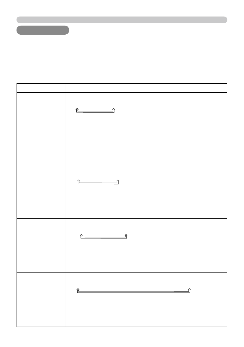
RESPONSE LIMIT TIME
This menu is available only when the NETWORK
BRIDGE is selected for the COMMUNICATION
TYPE and the HALF-DUPLEX is selected for the
TRANSMISSION METHOD.
Select the time period to wait for receiving response
data from other devise communicating by the
NETWORK BRIDGE and the HALF-DUPLEX through
the
CONTROL OUT
CONTROL OUT port.
OFF
1s
2s
3s
OFF: Select this mode if it is not required to check the
responses from the devise that the projector sends data
to. In this mode, the projector can send out data from
the computer continuously.
1s/2s/3s: Select the time period to keep the projector
waiting for response from the device that the projector
sends data to. While waiting the response, the projector
does not send out any data from the
CONTROL OUT
CONTROL OUT
port.
BYTES INTERVAL TIMEOUT
This menu is available only when NETWORK BRIDGE
is selected for the COMMUNICATION TYPE and HALF-
DUPLEX is selected for the TRANSMISSION METHOD.
Select the blank time length to judge that the response
data has fi nished in the communicating in the condition
of the NETWORK BRIDGE and the HALF-DUPLEX
through the
CONTROL OUT
CONTROL OUT port.
50ms
100ms
150ms
200ms
•
50ms is selected as the default setting.
NOTE
• OFF is selected as the default setting.
NOTE
55
OPTION menu
Item Description
SERVICE
(continued)
COMMUNICATION
(continued)
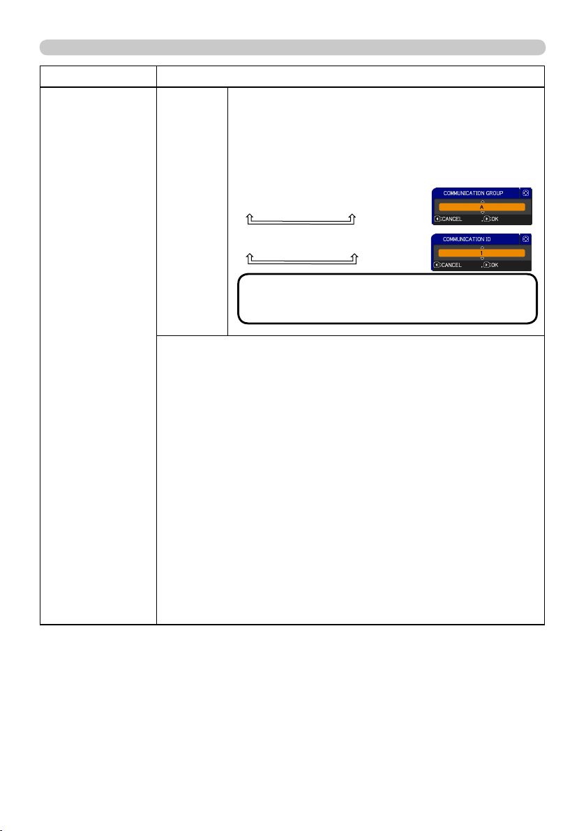
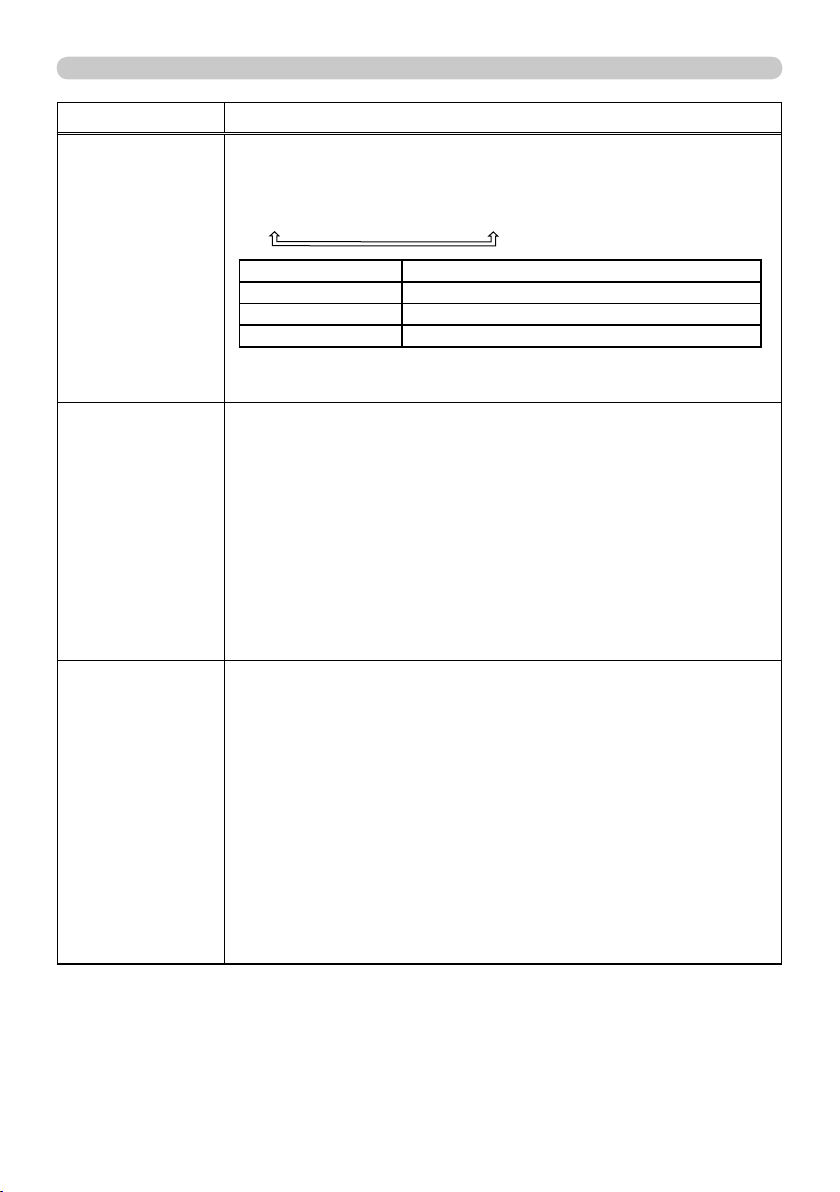
COMMUNICATION GROUP / COMMUNICATION ID
This menu is available only when DAISY CHAIN is
selected for the COMMUNICATION TYPE.
In simultaneous control of multiple projectors by
a daisy chain, you can give the projectors the
communication group identifi cation and the ID number
to identify projectors connected in the same bus.
COMMUNICATION GROUP:
A
B
C … O
P
COMMUNICATION ID:
1
2
3 … 63
64
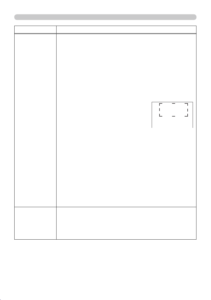
INFORMATION
Selecting this item displays a dialog titled “INPUT-INFORMATION-”.
It shows the information about the current input.
• The “FRAME LOCK” message on the dialog means the frame lock
function is working.
• The “SCART RGB” message means the Component port
is working as a SCART RGB input port. Please refer to the
COMPONENT item in INPUT menu (
37 ).
•
This item can't be selected for no signal and sync out.
• When the MY TEXT DISPLAY is set to ON, the MY TEXT
is displayed together with the input information in the INPUT-
INFORMATION- box (
66 ).
F
ACTORY RESET
Selecting OK using ►
the button performs this function. By this
function, all the items in all of menus will collectively return to the
initial setting. Note that the items LAMP TIME, FILTER TIME,
LANGUAGE, SECURITY and NETWORK settings are not reset.
CANCEL
OK
• The A is selected for the
COMMUNICATION GROUP, and 1 is selected for
the COMMUNICATION ID as the default settings.
NOTE

56
NETWORK menu
Remember that incorrect network settings on this
projector may cause trouble on the network. Be sure
to consult with your network administrator before
connecting to an existing access point on your
network.
Select “NETWORK” from the main menu to access
the following functions.
Select an item using the ▲/▼ cursor buttons on the projector or remote control,
and press the ► cursor button on the projector or remote control, or
ENTER
ENTER
button on the remote control to execute the item. Then perform it according to the
following table.
See the User’s Manual - Network Guide for details of NETWORK operation.
NETWORK menu
NETWORK menu
• If you are not utilizing SNTP (
Date/Time Settings of the User’s
Manual - Network Guide), then you must set the DATE AND TIME during the
initial installation.
NOTE
Item Description
SETUP
Selecting this item displays the SETUP
Menu for the network.
Use the ▲/▼ buttons to select an item,
and the ► or
ENTER
ENTER button on the remote
control to perform the item.
DHCP
(Dynamic
Host
Confi guration
Protocol)
Use the ▲/▼ buttons to turn DHCP on/off.
ON
OFF
Select OFF when the network does
not have DHCP enabled.
• When the “DHCP” setting changes to “ON”, it takes a
little time to obtain IP address from DHCP server.
• Auto IP function will be assigned an IP address if the
projector could not obtain an IP address from server
even if DHCP is “ON”.
(continued on next page)

57
NETWORK menu
Item Description
SETUP
(continued)
IP
ADDRESS
Use the ▲/▼/◄/►
buttons to enter the IP
ADDRESS.
This function can only be used when DHCP is set to
OFF.
• The IP ADDRESS is the number that identifi es this
projector on the network. You cannot have two devices
with the same IP ADDRESS on the same network.
• The IP ADDRESS “0.0.0.0” is prohibited.
SUBNET
MASK
Use the ▲/▼/◄/►
buttons to enter the same
SUBNET MASK used by
your PC.
This function can only be used when DHCP is set to
OFF.
• The SUBNET MASK ”0.0.0.0” is prohibited.
DEFAULT
GATEWAY
Use the ▲/▼/◄/►
buttons to enter the
DEFAULT GATEWAY
(a node on a computer network that serves as an
access point to another network) address.
This function can only be used when DHCP is set to
OFF.
DNS
SERVER
Use the ▲/▼/◄/►
buttons to input the DNS
server address.
The DNS server is a system to control domain names
and IP addresses on the Network.
TIME
DIFFERENCE
Use the ▲/▼ buttons to enter
the TIME DIFFERENCE.
Set the same TIME
DIFFERENCE as the one
set on your PC. If unsure,
consult your IT manager.
Use the ► button to return
to the menu after setting the
TIME DIFFERENCE.
DATE
AND
TIME
Use the ▲/▼/◄/►
buttons to enter the
Year (last two digits),
Month, Date, Hour and Minute.
• The projector will override this setting and retrieve
DATE AND TIME information from the Time server
when SNTP is enabled. (
Date/Time Settings of the
User’s Manual - Network Guide)
(continued on next page)

58
NETWORK menu
Item Description
PROJECTOR
NAME
(1) Use the▲/▼ buttons on the
NETWORK menu to select the
PROJECTOR NAME menu
and press the ► button. The
PROJECTOR NAME dialog will
be displayed.
(2) The current PROJECTOR NAME will be displayed on the fi rst 3
lines. If not yet written, the lines will be blank.
Use the ▲/▼/◄/► buttons and the
ENTER
ENTER or
VIDEO
VIDEO button to
select and enter characters.
The
RESET
RESET or
COMPUTER
COMPUTER button can be used to erase 1
character at a time. Also if you move the cursor to DELETE or
ALL CLEAR on screen and push the
ENTER
ENTER or
VIDEO
VIDEO button,
1 character or all characters will be erased.The PROJECTOR
NAME can be input up to 64 characters.
(3) To change an already inserted
character, press the ▲/▼ button
to move the cursor to one of the
fi rst 3 lines, and use the ◄/►
buttons to move the cursor on the
character to be changed. After
pressing the
ENTER
ENTER or
VIDEO
VIDEO
button, the character is selected.
Then, follow the same procedure
as described at the item (2) above.
(4) To fi nish entering text, move the cursor to the OK on screen and
press the ►,
ENTER
ENTER or
VIDEO
VIDEO button. To revert to the previous
PROJECTOR NAME without saving changes, move the cursor
to the CANCEL on screen and press the ◄,
ENTER
ENTER or
VIDEO
VIDEO
button.
(continued on next page)

59
NETWORK menu
Item Description
MY IMAGE
Selecting this item displays the MY
IMAGE menu.
The application software “PJImage”
is required to store image(s) into the
projector.
Use the ▲/▼ buttons to select an item which is a still image by the
MY IMAGE (
MY IMAGE (Still Image Transfer) Display of the
User’s Manual - Network Guide) and the ► or
ENTER
ENTER button to
display the image.
• The item without image stored cannot be selected.
• The image names are each displayed in 16 characters or less.
To switch the image displayed
Use the ▲/▼ buttons.
To return to the menu
Press the ◄ button on the remote control.
To erase the image displayed and its source fi le in the projector.
(1) Press the
RESET
RESET button on the
remote control while displaying an
image to display the MY IMAGE
DELETE menu.
(2) Press the ► button to perform to erase.
To stop erasing, press the ◄ button.
(continued on next page)
60
NETWORK menu
Item Description
INFORMATION
Selecting this item displays the NETWORK -INFORMATION- dialog
for confi rming the network settings.
• Only the first 16 characters of the projector neme are displayed.
• Nothing (blank) is shown in the “PROJECTOR NAME” field until
you setup the item (
58).
•
When the voltage level of the battery for the built in clock
decreases, the set time may become incorrect even though accurate
date and time are input. Replace the battery suitably
(
70).
• IP ADDRESS, SUBNET MASK and DEFAULT GATEWAY indicate
“0.0.0.0” when DHCP is ON and the projector has not gotten
address from DHCP server.
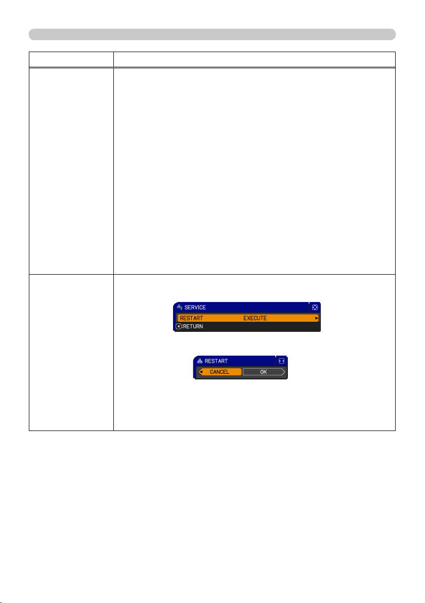
SERVICE
Executing this item restarts and initializes the network functions.
Choose the RESTART EXECUTE using the button ►.
Then use the button ► to execute.
Network will be once cut off when choose restart.
If DHCP is selected on, IP address may be changed.
After selecting RESTART EXECUTE, NETWORK menu may not be
controlled approx. 30 seconds.

62
SECURITY menu
Item Description
MyScreen
PASSWORD
The MyScreen PASSWORD function can be used to prohibit access to the
MyScreen function and prevent the currently registered MyScreen image
from being overwritten.
1 Turning on the MyScreen PASSWORD
1-1 Use the ▲/▼ buttons on the SECURITY menu
to select MyScreen PASSWORD and press the
► button to display the MyScreen PASSWORD
on/off menu.
1-2 Display the MyScreen password on/off menu
using the procedure in 2.1-1.
1-3 Use the ▲/▼ buttons on the MyScreen
PASSWORD on/off menu to select ON.
The ENTER PASSWORD box (small) will be
displayed.
1-4 Use the ▲/▼/◄/► buttons to enter the
password. Move the cursor to the right side
of the ENTER PASSWORD box (small) and
press the ► button to display the PASSWORD
AGAIN box, enter the same PASSWORD
again.
1-5 Move the cursor to the right side of the
PASSWORD AGAIN box and press the ►
button to display the NOTE PASSWORD box
for about 20 seconds, please make note of the
password during this time.
Pressing the
ENTER
ENTER button on the remote control or
VIDEO
VIDEO button on the
projector will return to MyScreen PASSWORD on/off menu.
When a password is set for MyScreen:
•
The MyScreen registration function (and menu) will be unavailable.
•
The MyScreen Lock menu will be unavailable.
•
The START UP setting will be locked on MyScreen (and the menu will be
unavailable).
Turning the MyScreen PASSWORD off will allow normal operation of these
functions.
•
Please do not forget your MyScreen PASSWORD.
2 Turning off the MyScreen PASSWORD
2-1 Follow the procedure in 1-1 to display the MyScreen PASSWORD on/off
menu.
2-2 Select OFF to display the ENTER PASSWORD box (large). Enter the
registered password and the screen will return to the MyScreen on/off
menu.
If an incorrect PASSWORD is input, the menu will close. If necessary, repeat
the process from 2-1.
3 If you have forgotten your password
3-1 Follow the procedure in 1-1 to display the MyScreen PASSWORD on/off
menu.
3-2
Select OFF to display the ENTER PASSWORD
box (large). The 10 digit Inquiring Code will be
displayed inside the box.
3-3 Contact your dealer with the 10 digit Inquiring
Code. Your password will be sent after your user
registration information is confi rmed.
ENTER PASSWORD box
(small)
(continued on next page)
ENTER PASSWORD box
(large)

63
SECURITY menu
Item Description
PIN LOCK
PIN LOCK is a function which prevents the projector from being used unless
a registered Code is input.
1 Turning on the PIN LOCK
1-1 Use the ▲/▼ buttons on the SECURITY menu
to select PIN LOCK and press the ► button or
the
ENTER
ENTER button to display the PIN LOCK on/
off menu.
1-2 Use the ▲/▼ buttons on the PIN LOCK on/off
menu to select ON and the Enter PIN Code box
will be displayed.
1-3 Input a 4 part PIN code using the ▲/▼/◄/►,
COMPUTER
COMPUTER button.
The PIN Code again box will appear. Reenter
the same PIN code. This will complete the PIN
code registration.
•
If there is no key input for about 55 seconds while
the Enter PIN Code box or the PIN Code again
box is displayed, the menu will close. If necessary,
repeat the process from 1-1.
Afterwards, anytime the projector is restarted after
the power switch is turned off the Enter PIN Code
box will be displayed. Enter the registered PIN code.
The projector can be used after entering the
registered PIN code. If an incorrect PIN code is
input, the Enter PIN code box will be displayed
again.
If an incorrect PIN Code is input 3 times, the projector will turn off.
Afterwards the projector will turn off every time an incorrect PIN code is
input. The projector will also turn off if there is no key input for about 5
minutes while the PIN BOX is displayed.
This function will activate only when the projector is started after the power
switch was turned off.
•
Please do not forget your PIN code.
2 Turning off the PIN LOCK
2-1 Follow the procedure in 1-1 to display the PIN LOCK on/off menu. Use
the ▲/▼ buttons to select OFF and the Enter PIN Code box will be
displayed.
Enter the registered PIN code to turn the PIN LOCK function off.
If an incorrect password is input 3 times, the menu will close.
3 If you have forgotten your PIN Code
3-1 While the Enter PIN Code box is displayed,
press and hold the
RESET
RESET button for three
seconds or press and hold the
COMPUTER
COMPUTER
button for 3 seconds while pressing the ►
button on the projector.
The 10 digit Inquiring Code will be displayed.
•
If there is no key input for about 5 minutes while the Inquiring Code is
displayed, the projector will turn off.
3-2 Contact your dealer with the 10 digit Inquiring Code. Your password will
be sent after your user registration information is confi rmed.
(continued on next page)

64
SECURITY menu
Item Description
TRANSITION
DETECTOR
If this function is set to ON when the vertical angle of
the projector or mirror setting at which the projector is
turned on is different than the previously recorded, the
TRANSITION DETECTOR ON alarm will be displayed
and the projector will not display the input signal.
•
To display the signal again, set this function OFF.
•
After about 5 minutes of displaying the TRANSITION DETECTOR ON alarm,
the lamp will turn off.
• Keystone adjustment feature has been prohibited as long as the Transition
Detector function is on.
1 Turning on the TRANSITION DETECTOR
1-1 Use the ▲/▼ buttons on the SECURITY menu to
select TRANSITION DETECTOR and press the ►
or the
ENTER
ENTER button to display the TRANSITION
DETECTOR on/off menu. Select ON and the
current angle and mirror setting will be recorded.
1-2 Use the ▲/▼ buttons on the SECURITY menu to select Transition
Detector and press the ► or the
ENTER
ENTER button to display the Transition
Detector on/off menu.
1-3 Use the ▲/▼ buttons on the TRANSITION
DETECTOR on/off menu to select ON. The
ENTER PASSWORD box (small) will be
displayed.
1-4
Use the
▲/▼/◄/►
buttons to enter a password.
Move the cursor to the right side of the ENTER
PASSWORD box (small) and press the
►
button
to display the PASSWORD AGAIN box, enter the
same password again.
1-5 Move the cursor to the right side of the
PASSWORD AGAIN box and press the ►
button to display the NOTE PASSWORD box
for about 20 seconds, please make note of the
password during this time.
• Pressing the
ENTER
ENTER button on the remote control or the
VIDEO
VIDEO button
on the projector will return to the TRANSITION DETECTOR on/off menu.
• Please do not forget your TRANSITION DETECTOR password.
• This function will activate only when the projector is started after the power
switch was turned off.
•
This feature may not function properly if the projector
is not in a stable position
when ON is selected.
2 Turning off the TRANSITION DETECTOR
2-1
Follow the procedure in 1-1 to display the Transition Detector on/off menu.
2-2 Select OFF to display the ENTER PASSWORD box (large). Enter the
registered password and the screen will return to the TRANSITION
DETECTOR on/off menu.
If an incorrect password is input, the menu will close. If necessary, repeat
the process from 3-1.
3 If you have forgotten your password
3-1
Follow the procedure in 1-1 to display the Transition Detector on/off menu.
3-2
Select OFF to display the ENTER PASSWORD box
(large). The 10 digit Inquiring Code will be displayed
inside the box.
3-3 Contact your dealer with the 10 digit Inquiring
Code. Your password will be sent after your
user registration information is confi rmed.
(continued on next page)
ENTER PASSWORD box
(small)
ENTER PASSWORD box (large)

65
SECURITY menu
Item Description
MY TEXT
PASSWORD
The MY TEXT PASSWORD function can prevent the MY TEXT from being overwritten.
• The MY TEXT DISPLAY menu will be unavailable, which can prohibit changing the
DISPLAY setting.
• The MY TEXT WRITING menu will be unavailable, which can prevent the MY TEXT
from being overwritten.
1 Turning on the MY TEXT PASSWORD
1-1 Use the ▲/▼ buttons on the SECURITY menu
to select the MY TEXT PASSWORD menu and
press the ► button to display the MY TEXT
PASSWORD on/off menu.
1-2 Display the MY TEXT PASSWORD on/off menu
using the procedure in 1-1
1-3 Use the ▲/▼ buttons on the MY TEXT
PASSWORD menu to select ON. The ENTER
PASSWORD box (small) will be displayed.
1-4 Use the ▲/▼/◄/► buttons to enter the
password. Move the cursor to the right side of
the ENTER PASSWORD box (small) and press
the ► button to display the PASSWORD AGAIN
box, and then enter the same password again.
1-5 Move the cursor to the right side of the
PASSWORD AGAIN box and press ► button to
display the NOTE PASSWORD box for about
20 seconds, then please make note of the
password during this time.
Pressing the
ENTER
ENTER button on the remote control
or
VIDEO
VIDEO button on the projector will return to the
MY TEXT PASSWORD on/off menu. When the
password is set for the MY TEXT;
2 Turning off the MY TEXT PASSWORD
2-1 Follow the procedure in 1-1 to display the MY
TEXT PASSWORD on/off menu.
2-2 Select OFF to display the ENTER PASSWORD
box (large). Enter the registered password
and the screen will return to the MY TEXT
PASSWORD on/off menu.
If an incorrect password is input, the menu will
close. If necessary, repeat the process from 2-1
3 If you have forgotten your password
3-1 Follow the procedure in 1-1 to display the MY TEXT PASSWORD on/off
menu.
3-2 Select OFF to display the ENTER PASSWORD box (large). The 10 digit
inquiring code will be displayed inside the box.
3-3 Contact your dealer with the 10 digit inquiring code. Your password will
be sent after your user registration information is confi rmed.
ENTER PASSWORD BOX
(small)
ENTER PASSWORD BOX
(large)
(continued on next page)

66
SECURITY menu
Item Description
MY TEXT
DISPLAY
1 Use the ▲/▼ buttons on the SECURITY menu to
select the MY TEXT DISPLAY menu and press the
► button to display the MY TEXT DISPLAY on/off
menu.
2 Use the ▲/▼ buttons on the MY TEXT DISPLAY
on/off menu to select on or off.
ON
OFF
When it is set ON, the MY TEXT will be displayed
on the START UP screen and the INPUT-
INFORMATION- when the INFORMATION on the
SERVICE menu is chosen.
• This function is available only when the MY TEXT
PASSWORD function is set to the OFF.
MY TEXT
WRITING
1 Use the ▲/▼ buttons on the SECURITY menu to
select the MY TEXT WRITING menu and press
the ► button. The MY TEXT WRITING dialog will
be displayed.
2
The current MY TEXT will be displayed on the fi rst 3
lines. If not yet written, the lines will be blank.
Use the
▲/▼/◄/►
buttons and the
ENTER
ENTER or
VIDEO
VIDEO button to select and enter
characters. The
RESET
RESET button can be used to erase 1 character at a time. Also if
you move the cursor to DELETE or ALL CLEAR on screen and push the
ENTER
ENTER
or
VIDEO
VIDEO button, 1 character or all characters will be erased. The MY TEXT can
be input up to 24 characters on each line.
3 To change an already inserted character,
press the ▲/▼ button to move the
cursor to one of the fi rst 3 lines, and use
the ◄/► buttons to move the cursor on
the character to be changed.
After pressing the
ENTER
ENTER or
VIDEO
VIDEO
button, the character is selected.
Then, follow the same procedure as
described at the item (2) above.
4 To fi nish entering text, move the cursor
to the OK on screen and press the
ENTER
ENTER or
VIDEO
VIDEO button. To revert
to the previous MY TEXT without
saving changes, move the cursor to
the CANCEL on screen and press the
ENTER
ENTER or
VIDEO
VIDEO button.
•
The MY TEXT WRITING function
is available only when the MY TEXT
PASSWORD function is set to OFF.
67
Maintenance
Maintenance
Maintenance
A worn out lamp bulb could burn or burst. It is recommended to keep a spare
lamp unit on hand and to replace the lamp unit when the projected image darkens
or color reproduction becomes poor.
To prepare the spare, contact your dealer and tell the following type number.
Lamp unit
Type number of the optional lamp unit: DT01001
•The value shown on the OPTION menu as the LAMP TIME is the use
time that is counted since the last time the LAMP TIME was reset. Refer to the
value for proper maintenance.
NOTE
If the projector is installed in a special state such as ceiling mount, or if the lamp
bulb has broken, also ask the dealer to replace the lamp unit. Otherwise, follow
the procedure shown below to replace the lamp.
Make sure that the projector is unplugged and
cooled down.
1.
6.
To display the ADVANCED MENU, press the
MENU
MENU button (on the control
panel or the remote control). On the EASY MENU, select the “ADVANCED
MENU” using the ▲/▼ cursor buttons, then press the ► cursor button.
To display the LAMP TIME dialog, select the
“LAMP TIME” using the ▲/▼ cursor buttons in
the right column, then press the ► cursor button.
Use the ► cursor button according to the dialog,
Selecting “OK” resets the LAMP TIME value.
(1)
(2)
(4)
(5)
Turn the projector on.
I O
HDMI DVI-D
CONTROL IN CONTROL OUT
REMOTE
CONTROL
IN
OUT
S-VIDEO
COMPUTER IN2
COMPUTER IN1
VIDEO 1
BNC
R/Cr/Pr G/Y B/Cb/Pb H V VIDEO 2
Y
Cb/Pb
Cr/Pr
AC IN
LAN
MONITOR
OUT
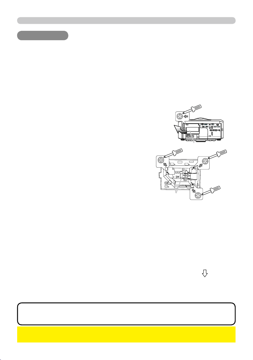
The lamp cover
The handles
Loosen the screw (marked by arrow) of the
lamp cover. Then slide and take it off.
2.
Loosen the 3 screws (marked by arrow) of the
lamp unit. Then picking the handles of the unit,
gently take it from the projector.
3.
Gently set the new lamp unit into place. Then
retighten the screws of the lamp unit.
4.
Put the lamp cover back into place, and
retighten the screw of the lamp cover.
5.
Reset the LAMP TIME value.
►Be sure to reset the LAMP TIME only when you have replaced the
lamp unit.
NOTICE
To select the OPTION menu, select the
“OPTION” using the ▲/▼ cursor buttons in the
left column, then press the ► cursor button.
(3)
68
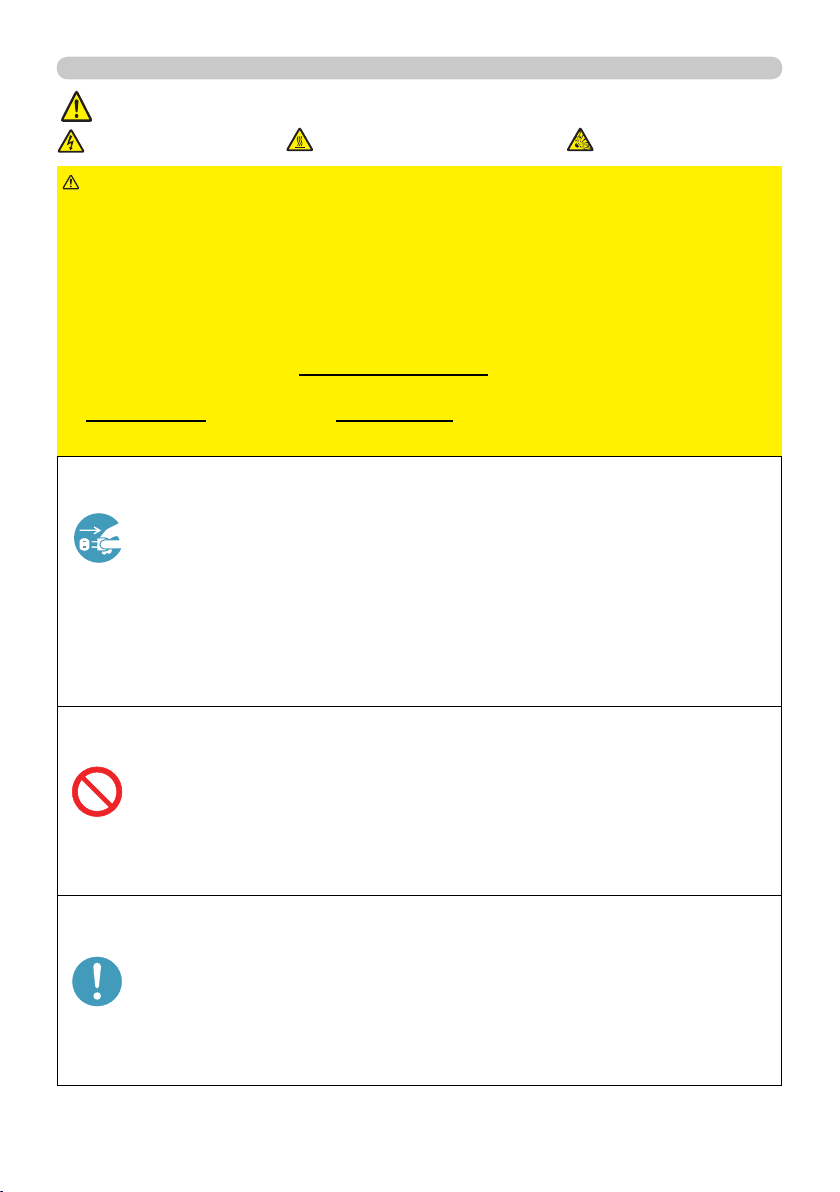
Maintenance
Lamp warning
HIGH VOLTAGE
HIGH TEMPERATURE HIGH PRESSURE
►The projector uses a high-pressure mercury glass lamp. The
lamp can break with a loud bang, or burn out, if jolted or scratched, handled
while hot, or worn over time. Note that each lamp has a different lifetime, and
some may burst or burn out soon after you start using them. In addition, when
the bulb bursts, it is possible for shards of glass to fl y into the lamp housing, and
for gas containing mercury to escape from the projector’s vent holes.
► About disposal of a lamp: This product contains a mercury lamp; do not put
it in a trash. Dispose of it in accordance with environmental laws.
• For lamp recycling, go to www.lamprecycle.org (in the US).
• For product disposal, contact your local government agency
or www.eiae.org (in the US) or www.epsc.ca (in Canada).
For more information, call your dealer.
WARNING
• If the lamp should break (it will make a loud bang when it does),
unplug the power cord from the outlet, and make sure to request a
replacement lamp from your local dealer. Note that shards of glass
could damage the projector’s internals, or cause injury during handling,
so please do not try to clean the projector or replace the lamp yourself.
• If the lamp should break (it will make a loud bang when it does),
ventilate the room well, and make sure not to breathe the gas that
comes out of the projector vents, or get it in your eyes or mouth.
• Before replacing the lamp, turn the projector off and unplug the power
cord, then wait at least 45 minutes for the lamp to cool suffi ciently.
Handling the lamp while hot can cause burns, as well as damaging the
lamp.
• Never unscrew except the appointed (marked by an arrow) screws.
• Do not open the lamp cover while the projector is suspended from
a ceiling. This is dangerous, since if the lamp’s bulb has broken, the
shards will fall out when the cover is opened. In addition, working in
high places is dangerous, so ask your local dealer to have the lamp
replaced even if the bulb is not broken.
• Do not use the projector with the lamp cover removed. At the lamp
replacing, make sure that the screws are screwed in fi rmly. Loose
screws could result in damage or injury.
• Use only the lamp of the specifi ed type.
• If the lamp breaks soon after the fi rst time it is used, it is possible
that there are electrical problems elsewhere besides the lamp. If this
happens, contact your local dealer or a service representative.
•
Handle with care: jolting or scratching could cause the lamp bulb to burst during use.
• Using the lamp for long periods of time, could cause it to darken, not
to light up or to burst. When the pictures appear dark, or when the color
tone is poor, please replace the lamp as soon as possible. Do not use
old (used) lamps; this is a cause of breakage.
Disconnect
the plug
from the
power
outlet

69
Maintenance
Filter cover
Filter unit knobs
Intake vents
To keep inside ventilation normal, keep a spare and replace the fi lter unit
periodically, although frequent replacement is not needed for this product.
To prepare the spare, contact your dealer and tell the following type number.
Type number of the optional fi lter unit: MU06351
1.
Make sure that the projector is
unplugged and cooled down.
2.
Use a vacuum cleaner on
and around the fi lter cover.
3.
Pick and pull up the fi lter
cover knobs to take it off.
4.
5.
Use a vacuum cleaner on and around
the intake vents of the projector.
6.
Set the new fi lter unit into the place.
Filter unit
Pinch and pull out the fi lter unit
knob to take it off.
• The value shown on the EASY menu as the FILTER TIME is the use
time that is counted since the last time the FILTER TIME was reset. Refer to
the value for proper maintenance.
• You can utilize the message function, which is set up by the item FILTER
TIME of the OPTION menu, to notify you when to replace the lamp.
NOTE
►Before checking or replacing the fi lter unit, turn off, unplug,
and cool down the projector.
►To keep inside ventilation normal, check and replace the fi lter unit periodically.
►Use only the manufacturer specifi ed type of the fi lter unit.
►Be sure to reset the FILTER TIME only when you have replaced
the fi lter unit.
WARNING
NOTICE
The following walks you through the steps to replace the fi lter unit.
7.
Put the fi lter cover back into the place.
8.
Reset the FILTER TIME value.
Turn the projector on.
To display the FILTER TIME dialog, select the
“FILTER TIME” using the ▲/▼ cursor buttons,
then press the ► cursor button.
Use the ► cursor button according to the dialog,
Selecting “OK” resets the FILTER TIME value.
(1)
(3)
(4)
To display the EASY MENU, press the MENU
button (on the control panel or the remote
control). On the ADVANCED MENU, select the
“EASY MENU” using the ▲/▼ cursor buttons in
the left column, then press the ► cursor button.
(2)
Filter cover knobs

70
Maintenance
Internal clock battery
►Be careful of handling battery, since a battery can cause explosion,
cracking or leakage that could result in a fi re, an injury, and environment pollution.
• Use only the specifi ed battery.
• When replacing the battery, replace it with a new battery.
• Do not use a battery with damage, such as scratches, dents, rust or leakage.
• Do not work on a battery; for example recharging or soldering.
• Keep a battery in a dark, cool and dry place. Never expose a battery to a fi re or water.
• Keep a battery away from children and pets. Be careful for them not to swallow a
battery.
• When a battery leaked, wipe the leakage out well with a waste cloth. If the leakage
adhered to your body, immediately rinse it well with water. When a battery leaked in the
battery holder, replace the batteries after wiping the leakage out.
• Obey the local laws on disposing a battery.
WARNING
This projector is being loaded with a battery for the internal clock that the network
function needs. When the clock does not work correctly, request your dealer
to check the battery and to replace if needed. For replacement, prepare a new
battery of the following type. You can buy it at the store or order it from your
dealer.
HITACHI MAXELL, part number CR2032 or CR2032H
Others
For the lens
For the inside of the projector
For the cabinet of the projector and remote control
Be careful not to scratch, crack, dirty, or fog the lens surface, since it affects the
image quality. When the lens surface is fogged or dirty, gently wipe it only with the
commercial cloth or paper lens cleaner.
In order to ensure the safe use of your projector, please have it cleaned and
inspected by your dealer about once every year.
For the dirty cabinet of the projector or remote control, use soft cloth. Dip a soft
cloth in water or a neutral cleaner diluted in water, and wipe the cabinet lightly
after wringing it well. Then, wipe again lightly with a soft and dry cloth.
►Before checking or cleaning the lens, turn off, unplug, and
cool down the projector.
►Do not scratch the projector and knock it against something. Use special
caution for the lens surface.
►Do not wet the product. Do not let any liquids enter to the inside. Do not use a
spray.
WARNING
►Do not directly touch the lens surface with hands.
►Do not use cleaners or chemicals other than those specifi ed in this manual.
NOTICE

71
Troubleshooting
Troubleshooting
Troubleshooting
Related messages
When the unit's power is on, messages such as those shown below may be
displayed. When any such message is displayed on the screen, please follow the
instructions described below. If the same message is displayed after the remedy,
or if a message other than the following appears, please contact your dealer or
service company.
Although these messages will automatically disappear after several minutes, they
will be displayed again when the power is turned on.
Message Description
There is no input signal.
Please confi rm the signal input connection, and the status of the signal source.
The horizontal or vertical frequency of the input signal is not
within the specifi ed range.
Please confi rm the specs for your projector or the signal source specs.
An improper signal is input.
Please confi rm the specs for your projector or the signal source specs.
The internal temperature is rising too much.
Turn the projector off (
20) soon, and allow it to cool down for 20
minutes or more.
After cooling, perform the following check.
- Are there any obstacles to ventilation around the projector?
- Does the temperature around the projector exceed the limit
specifi ed? (
77 )
When this message is displayed without the obstacles mentioned
above, replacement of the fi
lter unit is required. Replace the fi lter
unit soon according to the procedure directed in the paragraph
"Filter unit" in the chapter "Maintenance" (
69 ). Remember
resetting the FILTER TIME is needed soon after replacement of
the fi lter unit.
Replacement of the fi lter unit is required.
The value of the timer of the FILTER TIME reached the preset
value of the FILTER MESSAGE on the SERVICE menu under the
OPTION menu (
50 ). Replace the fi lter unit soon according to
the procedure directed in the paragraph "Filter unit" in the chapter
"Maintenance" (
69 ). Remember resetting the FIL
TER TIME is
needed soon after replacement of the fi lter unit.
The button operation is not available with following
condition.
- While the lens is moving, button operation from the control panel
or the remote control might be ignored. Wait for the LENS SHIFT
indicator stopping blinking.
- Pressing the one of buttons to call a signal input might be ignored,
when all the input ports belonging to the category the button's
name shows are set to the "SKIP" by the item SOURCE SKIP of
the OPTION menu.
74
Troubleshooting
Phenomena that may be easily mistaken for machine defects
►
Never use the projector if abnormal operations such as smoke,
strange odor, excessive sound, damaged casing or elements or cables, penetration
of liquids or foreign matter, etc. should occur. In such cases, immediately turn off the
power switch and then disconnect the power plug from the power outlet. After making
sure that the smoke or odor has stopped, contact your dealer or service company.
WARNING
(Continued on next page)
Phenomenon Cases not involving a machine defect
Reference
page
Power does not
come on.
The electrical power cord is not plugged in.
Correctly connect the power cord.
15
The power switch is not set to the on position.
Set the power switch to [
|
| ] (on).
19
The main power source has been interrupted during
operation such as by a power outage (blackout), etc.
Please turn the power off, and allow the projector to cool
down at least 2 minutes, then turn the power on again.
19, 20
Either there is no lamp and/or lamp cover, or either
of these has not been properly fi xed.
Please turn the power off, and allow the projector to cool down at
least 45 minutes. After the projector has suffi ciently cooled down,
please make confi rmation of the attachment state of the lamp and
lamp cover, and then turn the power on again.
67
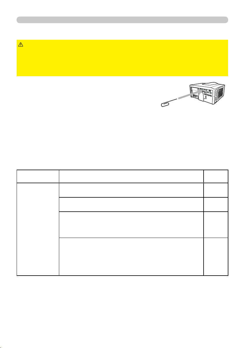
Before requesting repair, please check in accordance
with the following chart. This operation sometimes
resolves your problem.
If the situation cannot be corrected;
- The projector’s microprocessor may need to be reset.
Please push the Shutdown switch by using a pin or similar and the projector will
be turned off immediately. Before turning it again, wait at least 10 minutes to
make the projector cool down enough.
- Some setting may be wrong. Please use the FACTORY RESET function of
the SERVICE item in the OPTION menu (
55 ) to reset all settings to factory
default. Then, if the problem is not removed after the remedy, please contact
your dealer or service company.

75
Troubleshooting
(Continued on next page)
Phenomenon Cases not involving a machine defect
Reference
page
No picture is
displayed.
The signal cables are not correctly connected.
Correctly connect the connection cables.
11
The brightness is adjusted to an extremely low level.
Adjust BRIGHTNESS to a higher level using the menu
function or the remote control.
31
The computer cannot detect the projector as a plug and play monitor.
Make sure that the computer can detect a plug and play
monitor using another plug and play monitor.
14
The BLANK screen is displayed.
Press the
BLANK
BLANK button on the remote control.
26
The shutter is closed.
Press the
SHUTTER
SHUTTER button.
26
No pictures
or disturbed
pictures are
displayed on
HDMI
HDMI input.
The HDMI cable is not correctly connected.
Correctly connect the HDMI cable.
11
Your HDMI equipment is not compatible with the projector
This projector can be connected with another equipment
that has HDMI or DVI connector, but with some equipment
the projector may not work properly.
14
Your HDMI equipment and the projector are not harmonized.
Turn off the both equipment, and turn on them again
–
The signal format on the HDMI is not supported.
Check the video setting on your HDMI equipment.
14

76
Troubleshooting
• Although bright spots or dark spots may appear on the screen, this
is a unique characteristic of liquid crystal displays, and it does not constitute or
imply a machine defect.
NOTE
Phenomenon Cases not involving a machine defect
Reference
page
Video screen
display freezes.
The FREEZE function is working.
Press the
FREEZE
FREEZE button to restore the screen to normal.
25
Colors have a
faded- out
appearance, or
Color tone is
poor.
Color settings are not correctly adjusted.
Perform picture adjustments by changing the COLOR
TEMP, COLOR, TINT and/or COLOR SPACE settings,
using the menu functions.
32, 36
COLOR SPACE setting is not suitable.
Change the COLOR SPACE setting to AUTO, RGB,
SMPTE240, REC709 or REC601.
36
Pictures appear
dark.
The brightness and/or contrast are adjusted to an
extremely low level.
Adjust BRIGHTNESS and/or CONTRAST settings to a
higher level using the menu function.
31
The ECO MODE function is working.
Select NORMAL for the ECO MODE item in the SETUP
menu.
30, 41
The lamp is approaching the end of its product
lifetime.
Replace the lamp.
67, 68
Pictures appear
blurry.
Either the focus and/or horizontal phase settings are
not properly adjusted.
Adjust the focus using the
FOCUS
FOCUS button, and/or H PHASE
using the menu function.
21
The lens is dirty or misty.
Clean the lens referring to the section “For the lens” in
"Others".
70
Pictures are
trembling.
The exhaust ventilation holes at front is blocked by
some objects.
Remove any objects from front side of the projector.
10
78
Specifi cations
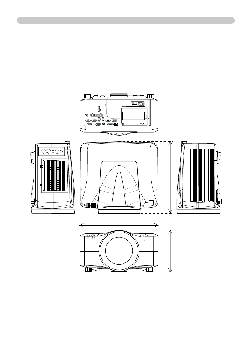
Specifi cations (continued)
[unit: mm]
I O
476
469
272

27
Operating
Most of operations are effective for the main area
only. Also the audio input signal paired with the
picture input signal for the main area is assigned
as the audio output signal. The main area can be
changed using the cursor buttons ◄/► when the
setting information is on the screen.
PbyP (Picture by Picture)
The PbyP is a function to display two different picture signals on a screen that is
split in two areas for each signal. Some of functions can be used with the same
operation as it for the normal mode (not in the PbyP mode). There are some
operations available only in the PbyP mode.
The setting information is displayed for several
seconds when the PbyP function is started. It shows
the input signal information for each area. Also, there
will be a yellow frame and speaker mark with one of the area that is the main area
where most of operations are effective. The information can be displayed using
the cursor buttons ▲/▼/◄/► when the setting information is not on the screen.
Press the
PbyP
PbyP button on the
remote control, then the PbyP
function will be started. To quit
the PbyP mode, press the button
again.
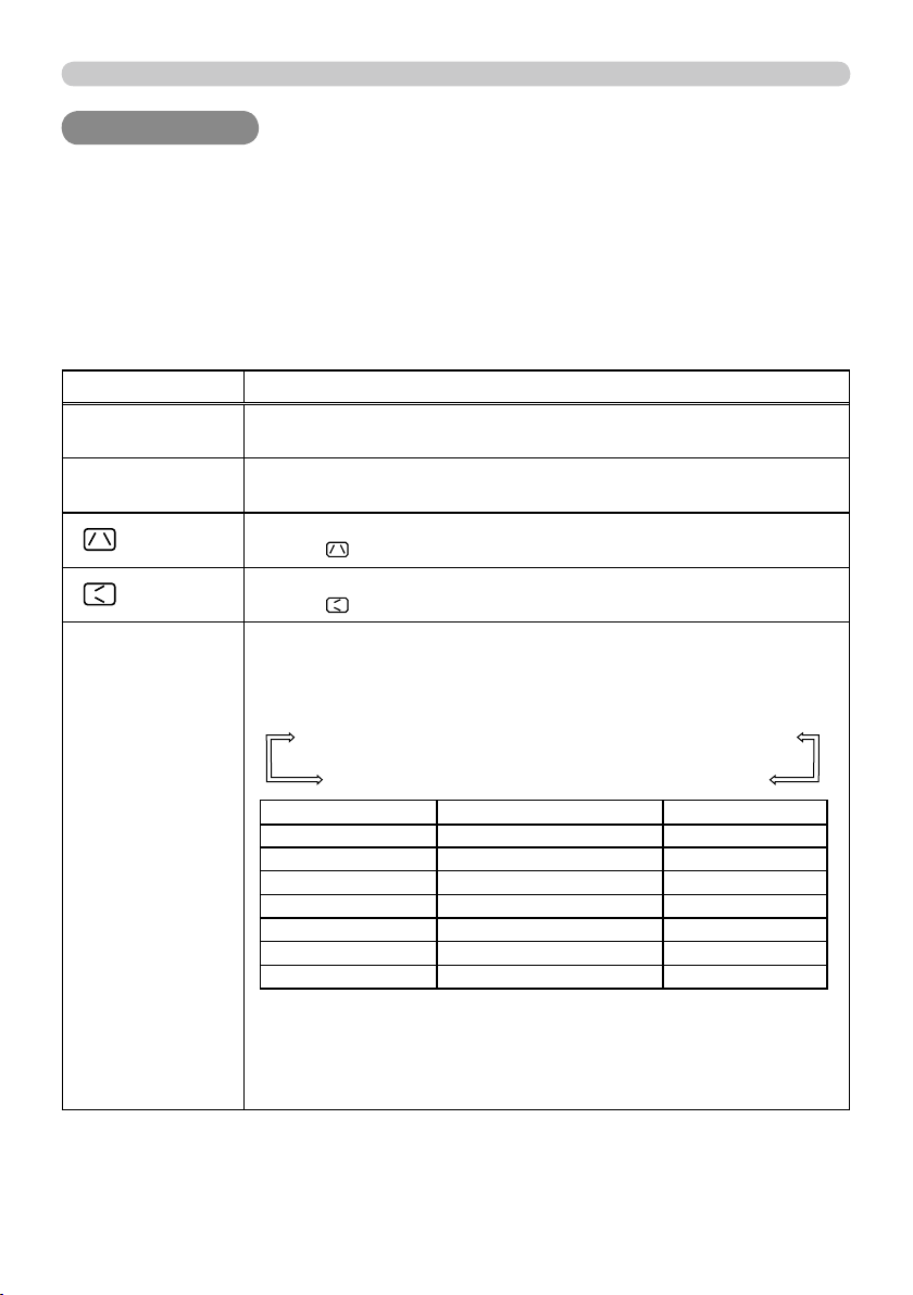
Press the
COMPUTER
COMPUTER,
VIDEO
VIDEO or
DIGITAL
DIGITAL button
while in the PbyP mode, the menu to select the
input signal will be appeared. Choose a signal using
the cursor buttons ▲/▼. If you want to change the signal in
the sub area, switch the main area using the cursor buttons
◄/► fi rst. Displaying the same signal on the both areas is
not allowed. For other combinations of the input signal, refer
to the right table. Any combinations marked with X can not be
selected.
<signal combination>
Press the
MY BUTTON
MY BUTTON assigned the PbyP SWAP
(
49 ). The position of the both area is exchanged
without any setting change.
Starting the PbyP
Changing the main area
Showing the setting information
Changing the picture input signal
Using the PbyP SWAP function
normal mode PbyP mode
•For some signals, it may not be displayed correctly in the PbyP mode,
even if it can be displayed properly in the normal mode.
NOTE
main area
sub area
main area
Sub
Main
COMPUTER IN1
COMPUTER IN2
BNC
HDMI
DVI-D
Component
Scart RGB
S-Video
Video 1
Video 2
COMPUTER IN1
000000000
COMPUTER IN2
0 00000000
BNC 00 0000000
HDMI 0 0 0 X 0 XXXX
DVI-D 0 0 0 X 0 XXXX
Component
00000 000
Scart RGB
000XX XXX
S-Video
000XX0X XX
Video 1
000XX0XX X
Video 2
000XX0XXX
FREEZE
AUTO
ASPECT
RESET
MENU
POSITION
PbyP
SHUTTER
setting information
28
Operating
BLANK LASER
FREEZE
LASER
INDICATOR
DIGITAL
STANDBY/ON COMPUTER
LENS SHIFT
KEYSTONE
ID 3
ID 4
ID 2
ID 1
VIDEO
AUTO
ASPECT
RESET
MENU
MAGNIFY
ON
OFF
3
4
ENTER
FOCUS
+
-
POSITION
PbyP
ZOOM
+
-
1
2
MY BUTTON
MY SOURCE
SHUTTER
FREEZE
ASPECT
RESET
MENU
ENTER
SHUTTER
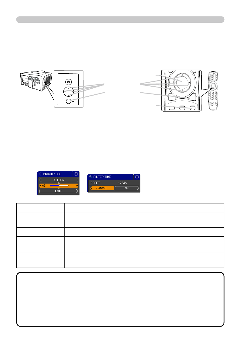
To start the MENU, press the
MENU
MENU button. The MENU
you last used (EASY or ADVANCED) will appear. EASY
MENU has priority to appear just after powered on. To
fi nish the MENU, press the
MENU
MENU button again.
If you want to change it to EASY/ADVANCED MENU,
select the EASY/ADVANCED MENU on the menu.
Using the menu function
●
If you want to move the menu position, use the
▲/▼/◄/►
buttons after pressing
the
POSITION
POSITION button.
● Some functions cannot be performed when a certain input port is selected, or
when a certain input signal is displayed.
●
When you want to reset the operation, press the
RESET
RESET button on the remote control
during the operation. Note that items whose functions are performed simultaneously with
operation (ex. LANGUAGE, H PHASE etc.) cannot be reset.
●
Even if you do not do anything, the dialog will automatically disappear after about 30 seconds.
This projector has the following menus: PICTURE, IMAGE, INPUT, SETUP, SCREEN, OPTION,
NETWORK, SECURITY and EASY MENU. The EASY MENU consists of functions often used, and
the other menus are classifi ed into each purpose and brought together as the ADVANCED MENU.
Each of these menus is operated using the same methods with the ▲/▼/◄/►,
ENTER
ENTER and
RESET
RESET
buttons. The buttons of the same name on the remote control and on the projector function equally.
Indication in OSD (On Screen Display)
RESET
RESET button
ENTER
ENTER button
MENU
MENU button
Cursor buttons
STANDBY/ON
MENU
The meanings of the general words on the OSD are as follows.
Start / fi nish the menu
NOTE
Indication Meaning
EXIT
Selecting this word fi nishes the OSD menu. It's the same as pressing the
MENU
MENU button.
RETURN Selecting this word returns the menu to the previous menu.
CANCEL or NO
Selecting this word cancels the operation in the present menu and
returns to the previous menu.
OK or YES
Selecting this word executes the prepared function or shifts the menu to
the next menu.
29
EASY MENU
EASY MENU
EASY MENU
From the EASY MENU, items shown in the table
below can be performed.
Select an item using the ▲/▼ cursor buttons on the
projector or remote control. Then perform it according
to the following table.
Item Description
ASPECT
Using the ◄/► buttons switches the mode for aspect ratio.
See the ASPECT item in IMAGE
menu
(
34 ).
AUTO
KEYSTONE
Using the ► button executes the auto keystone function.
See the AUTO KEYSTONE item in SETUP menu
(
40 ).
KEYSTONE
Using the ◄/► buttons corrects the vertical keystone distortion.
See the
KEYSTONE item in SETUP menu
(
40 ).
KEYSTONE
Using the ◄/► buttons corrects the horizontal keystone distortion.
See the
KEYSTONE item in SETUP menu
(
41 ).
PICTURE MODE
Using the ◄/► buttons switches the picture mode.
The picture modes are combinations of GAMMA and COLOR
TEMP settings. Choose a suitable mode according to the projected
source.
NORMAL
CINEMA
DYNAMIC
BOARD(BLACK)
DAYTIME
WHITEBOARD
BOARD(GREEN)
COLOR TEMP GAMMA
NORMAL 2 MID 1 DEFAULT
CINEMA 3 LOW 2 DEFAULT
DYNAMIC 1 HIGH 3 DEFAULT
BOARD(BLACK) 4 Hi-BRIGHT-1 4 DEFAULT
BOARD(GREEN) 5 Hi-BRIGHT-2 4 DEFAULT
WHITEBOARD 2 MID 5 DEFAULT
DAYTIME 6 Hi-BRIGHT-3 6 DEFAULT
• When the combination of GAMMA and COLOR TEMP differs
from pre-assigned modes above, the display on the menu for the
PICTURE MODE is “CUSTOM”. Please refer to the GAMMA and
COLOR TEMP (
31, 32 ) items in PICTURE menu.
•
When this function is performed, lines or other distiortions may appear.
(continued on next page)
31
PICTURE menu
PICTURE menu
PICTURE menu
From the PICTURE menu, items shown in the table
below can be performed.
Select an item using the ▲/▼ cursor buttons on the
projector or remote control, and press the ► cursor
button on the projector or remote control, or the
ENTER
ENTER button on the remote control to execute the
item. Then perform it according to the following table.
Item Description
BRIGHTNESS
Using the
◄/►
buttons adjusts the brightness.
Dark
Light
CONTRAST
Using the
◄/►
buttons adjusts the contrast.
Weak
Strong
GAMMA
Using the ▲/▼ buttons switches the gamma mode.
To adjust CUSTOM
Selecting a mode whose name includes CUSTOM and then
pressing the ► button or the
ENTER
ENTER button displays a dialog to aid
you in adjusting the mode.
This function is useful when you want to
change the brightness of particular tones.
Choose an item using the ◄/► buttons, and
adjust the level using the ▲/▼ buttons.
You can display a test pattern for checking the effect of your
adjustment by pressing the
ENTER
ENTER or
VIDEO
VIDEO button.
Each time you press the
ENTER
ENTER or
VIDEO
VIDEO button,
the pattern changes as below.
No pattern
Gray scale of 9 steps
Ramp
Gray scale of 15 steps
The eight equalizing bars correspond to eight tone levels of the test
pattern (Gray scale of 9 steps) except the darkest in the left end.
If you want to adjust the 2nd tone from left end on the test pattern,
use the equalizing adjustment bar “1”. The darkest tone at the left
end of the test pattern cannot be controlled with any of equalizing
adjustment bar.
• When this function is performed, lines or
other distortions may appear.
(continued on next page)
1DEFAULT
1CUSTOM
2DEFAULT
2CUSTOM
3DEFAULT
6CUSTOM3CUSTOM
6DEFAULT
5CUSTOM
5DEFAULT
4CUSTOM
4DEFAULT
34
IMAGE menu
IMAGE menu
IMAGE menu
From the IMAGE menu, items shown in the table
below can be performed.
Select an item using the ▲/▼ cursor buttons on the
projector or remote control, and press the ► cursor
button on the projector or remote control, or
ENTER
ENTER
button on the remote control to execute the item.
Then perform it according to the following table.
Item Description
ASPECT
Using the ▲/▼ buttons switches the mode for aspect ratio.
For a COMPUTER signal
NORMAL
4:3
16:9
16:10*
SMALL*
NATIVE*
FULL*
For an HDMI or DVI-D signal
NORMAL
4:3
16:9
16:10*
14:9
SMALL*
NATIVE*
FULL*
For a Video signal, S-video signal or component video signal
4:3
16:9
16:10*
14:9
SMALL*
NATIVE*
FULL*
For no signal
4:3 (fi xed, except CP-WX11000) / FULL (fi xed, CP-WX11000)
• *16:10 / FULL: CP-WX11000 only. NATIVE: Except CP-X10000.
SMALL: Except CP-WX11000.
• The NORMAL mode keeps the original aspect ratio of the signal.
OVER SCAN
Using the ◄/► buttons adjusts the over-scan ratio.
Small (It magnifi es picture)
Large (It reduces picture)
•
This item can be selected only for a video, s-video, component and HDMI or
DVI-D signal
when the VIDEO is selected on the DIGITAL FORMAT item
(
37 )
.
• When this adjustment is too large, certain degradation may appear
at the frame area of the picture. In such a case, please adjust small.
V POSITION
Using the ◄/► buttons adjusts the vertical position.
Down
Up
•
Over-adjusting the vertical position may cause noise to appear on the screen. If this
occurs, please reset the vertical position to the default setting. Pressing the
RESET
RESET
button when the V POSITION is selected will reset the V POSITION to the default setting.
•
When this function is performed on a video signal, s-video signal, or component video
signal of 480i@60 or 576i@50 input the range of this adjustment depends on the OVER
SCAN
(
above )
setting. It is not possible to adjust when the OVER SCAN is set to 10.
• This item cannot be selected for an HDMI or DVI-D signal.
H POSITION
Using the ◄/► buttons adjusts the horizontal position.
Right
Left
•
Over-adjusting the horizontal position may cause noise to appear on the screen. If this
occurs, please reset the horizontal position to the default setting. Pressing the
RESET
RESET
button when the H POSITION is selected will reset the H POSITION to the default setting.
•
When this function is performed on a video signal, s-video signal, or component video
signal of 480i@60 or 576i@50 input the range of this adjustment depends on the OVER
SCAN
(
above )
setting. It is not possible to adjust when the OVER SCAN is set to 10.
• This item cannot be selected for an HDMI or DVI-D signal.
(continued on next page)

35
IMAGE menu
Item Description
H PHASE
Using the
◄/►
buttons adjusts the horizontal phase to eliminate fl icker.
Right
Left
• This item can be selected only for a computer signal or a
component video signal. (except 480i@60, 576i@50, SCART RGB
input. )
H SIZE
Using the ◄/► buttons adjusts the horizontal size.
Large
Small
• This item can be selected only for a computer signal.
• When this adjustment is excessive, the picture may not be
displayed correctly. In such a case, please reset the adjustment
by pressing the
RESET
RESET button on the remote control during this
operation.
AUTO ADJUST
EXECUTE
Selecting this item performs the automatic adjustment feature.
For a computer signal
The vertical position, the horizontal position and the horizontal
phase will be automatically adjusted.
Make sure that the application window is set to its maximum size
prior to attempting to use this feature. A dark picture may still be
incorrectly adjusted. Use a bright picture when adjusting.
For a video signal and s-video signal
The video format best suited for the respective input signal will
be selected automatically. This function is available only when
the AUTO is selected for the VIDEO FORMAT item in the INPUT
menu (
37 ). The vertical position and horizontal position will be
automatically set to the default.
For a component video signal
The vertical position, horizontal position and horizontal phase will
be automatically set to the default.
• The automatic adjustment operation requires approx. 10 seconds.
Also please note that it may not function correctly with some input.
When this function is performed for a video signal, a certain extra
such as a line may appear outside a picture.
• The items adjusted by this function may vary when the FINE or
DISABLE is selected for the AUTO ADJUST item of the SERVICE
item in the OPTION menu (
50 ).
36
INPUT menu
INPUT menu
INPUT menu
From the INPUT menu, items shown in the table
below can be performed.
Select an item using the ▲/▼ cursor buttons on the
projector or remote control, and press the ► cursor
button on the projector or remote control, or
ENTER
ENTER
button on the remote control to execute the item.
Then perform it according to the following table.
Item Description
PROGRESSIVE
Using the ▲/▼ buttons switches the progress mode.
TV
FILM
OFF
• This function is performed only for an interlaced signal at the
VIDEO 1
VIDEO 1,
VIDEO 2
VIDEO 2 or
S-VIDEO
S-VIDEO input, and for 480i@60, 576i@50
or 1080i@50/60 signal at the Component,
HDMI
HDMI or
DVI-D
DVI-D input.
• When TV or FILM is selected, the screen image will be sharp.
FILM adapts to the 2-3 Pull-Down conversion system. But these
may cause a certain defect (for example, jagged line) of the picture
for a quick moving object. In such a case, please select OFF, even
though the screen image may lose sharpness.
VIDEO NR
Using the ▲/▼ buttons switches the noise reduction mode.
HIGH
MID
LOW
• This function is performed only for the
VIDEO 1, VIDEO 2
VIDEO 1, VIDEO 2 or
S-VIDEO
S-VIDEO input, and for 480i@60, 576i@50 or 1080i@50/60 signal
at the Component,
HDMI
HDMI or
DVI-D
DVI-D input.
• When this function is excessive, it may cause a certain
degradation of the picture.
3D-YCS
Using the ▲/▼ buttons switches the 3D-YCS mode.
STILL
MOVIE
OFF
• This function performs only at a
VIDEO 1
VIDEO 1 or
VIDEO 2
VIDEO 2 input of
NTSC, and PAL.
• MOVIE is the mode for images with a lot of motions like movies,
and STILL is the mode for images with few motions or completely
still ones like slides.
COLOR SPACE
Using the ▲/▼ buttons switches the mode for color space.
AUTO
RGB
SMPTE240
REC709
REC601
• This item can be selected only for an RGB signal or a component
video signal (except 480i@60, 576i@50 and SCART RGB).
• The AUTO mode automatically selects the optimum mode.
• The AUTO operation may not work well at some signals. In such a
case, it might be good to select a suitable mode except AUTO.
(continued on next page)
38
INPUT menu
Item Description
DIGITAL RANGE
(1) Use the ▲/▼ buttons to select the input port.
(2) Using the ◄/► cursor buttons changes the
digital signal mode.
AUTO
NORMAL
ENHANCED
Feature
AUTO Selecting the optimum mode automatically.
NORMAL Suitable for DVD signals (16-235)
ENHANCED Suitable for computer signals (0-255)
• If the contrast of the screen image is too strong or too weak, try
fi nding a more suitable mode.
COMPUTER IN
Set the computer input signal type for the
COMPUTER IN
COMPUTER IN port.
(1) Use the ▲/▼ buttons to select the
COMPUTER IN
COMPUTER IN port to be
set.
(2) Use the ◄/► buttons to select
the computer input signal type.
• Selecting the AUTO mode allows
you to input a sync on G signal or
component signal from the port.
• In the AUTO mode, the picture may be distorted with certain
input signals. In such a case, remove the signal connector so that
no signal is received and select the SYNC ON G OFF, and then
reconnect the signal.
FRAME LOCK
Set the frame lock function on/off for
each port.
(1) Use the ▲/▼ buttons to select
the input ports.
(2) Use the ◄/► buttons to turn the
frame lock function on/off .
ON
OFF
• This item can be performed only
on a signal with a vertical frequency
of 50 to 60 Hz.
• When ON is selected, moving pictures are displayed more
smoothly.
• This function may cause a certain degradation of the picture. In
such a case, please select OFF.
(continued on next page)

39
INPUT menu
Item Description
RESOLUTION
The resolution for the
COMPUTER IN1, COMPUTER IN2
COMPUTER IN1, COMPUTER IN2 and
BNC
BNC
input signals can be set on this projector.
(1) In the INPUT menu select the RESOLUTION using the ▲/▼ buttons and
press the ► button.
The RESOLUTION menu will be displayed.
(2) In the RESOLUTION menu select the
resolution you wish to display using the ▲/▼
buttons.
Selecting AUTO will set a resolution
appropriate to the input signal.
(3) Pressing the ► or
ENTER
ENTER button when
selecting a STANDARD resolution will
automatically adjust the horizontal and
vertical positions, clock phase and horizontal
size.
The INPUT-INFORMATION- dialog (
55 )
will be displayed.
(4)
To set a custom resolution use the
▲/▼ buttons to select the CUSTOM and
the CUSTOM RESOLUTION BOX will be
displayed. Set the horizontal (HORZ) and
vertical (VERT) resolutions using the
▲/▼/◄/► buttons.
This function is may not support all
resolutions.
(5) To save the setting place the cursor on the
right-most digit and press the ► button.
The horizontal and vertical positions, clock
phase and horizontal size will be automatically
adjusted.
After the INPUT-INFORMATION- dialog
(
55 ) has displayed for about 10 seconds
the screen will return to the RESOLUTION
menu displaying the changed resolution.
(6)
To revert back to the previous resolution
without saving changes place the cursor on
the left-most digit and press the ◄ button.
The screen will then return to the RESOLUTION menu displaying the
previous resolution.
• For some pictures, this function may not work well.

40
SETUP menu
SETUP menu
SETUP menu
From the SETUP menu, items shown in the table
below can be performed.
Select an item using the ▲/▼ cursor buttons on the
projector or remote control, and press the ► cursor
button on the projector or remote control, or the
ENTER
ENTER button on the remote control to execute the
item. Then perform it according to the following table.
Item Description
AUTO
KEYSTONE
Selecting this item performs the Automatic keystone distortion
correction. Projector automatically corrects vertical keystone
distortion due to the (forward/backward) setup angle by itself.
This function will be executed only once when selected in the menu.
When the slant of the projector is changed, execute this function
again.
• The adjustable range of this function will vary among inputs. For
some input, this function may not work well.
• When V:INVERT or H&V:INVERT is selected to the MIRROR item
in the SETUP menu, if the projector screen is inclined or angled
downward, this function may not work correctly.
• When the zoom adjustment is set to the TELE (telephoto focus),
this function may be excessive. This function should be used when
the zoom adjustment is set to the full WIDE (wide-angle focus)
whenever possible.
• When the projector is placed on the level (about ±3°), this function
may not work.
• When the projector is inclined to near ±30 degree or over, this
function may not work well.
• When the vertical lens shift is not set fully upward (not set fully
downward for the optional lens type USL-801 only (
51 ), this
function may not work well.
• When the horizontal lens shift is not set to the center
, this function
may not work well.
• This function will be unavailable when the Transition Detector is
on (
64 ).
KEYSTONE
Using the ◄/► buttons corrects the vertical keystone distortion.
Shrink the bottom of the image
Shrink the top of the image
• The adjustable range of this function will vary among inputs. For
some input, this function may not work well.
• When the horizontal lens shift is not set to the center, this function
may not work well.
• This function will be unavailable when the Transition Detector is
on (
64 ).
(continued on next page)

41
SETUP menu
Item Description
KEYSTONE
Using the ◄/► buttons corrects the horizontal keystone distortion.
Shrink the left of the image
Shrink the right of the image
• The adjustable range of this function will vary among inputs. For
some input, this function may not work well.
• When the zoom adjustment is set to the TELE (telephoto focus),
this function may be excessive. This function should be used when
the zoom adjustment is set to the full WIDE (wide-angle focus)
whenever possible.
• When the vertical lens shift is not set fully upward (not set fully
downward for the optional lens typeUSL-801 only (
51 ), this
function may not work well.
•
This function will be unavailable when the Transition Detector is on
(
64 ).
ECO MODE
Using the ▲/▼ buttons turns of
f/on the eco mode.
NORMAL
ECO
• When the ECO is selected, acoustic noise and screen brightness
are reduced.
MIRROR
Using the ▲/▼ buttons switches the mode for mirror status.
NORMAL
H:INVERT
V:INVERT
H&V:INVERT
If the Transition Detector is on and MIRROR status is changed,
Transition Detector alarm (
64 ) will be displayed when projector is
restarted after the power switch is turned off.
・
When the "MIRROR" has been set to the "V:INVERT", the screen
will be turned upside down, after the menu dialog disappeared.
MONITOR OUT
The combination of a picture shown on screen and output from the
MONITOR OUT
MONITOR OUT port can be arranged in the menu.
The picture coming into the port selected in the (2) is output to the
MONITOR OUT
MONITOR OUT port while an image from the port chosen in the (1)
is on screen.
(1) Choose a picture input port using ▲/▼ buttons.
• Choose STANDBY, to select the output signal from the
MONITOR
MONITOR
OUT
OUT port in the standby mode.
(2) Select one of the
COPUTER IN
COPUTER IN or
BNC
BNC ports using ◄/► buttons.
COMPUTER IN1
COMPUTER IN2
OFF
BNC
• OFF disables the
MONITOR OUT
MONITOR OUT port.
42
SCREEN menu
SCREEN menu
SCREEN menu
From the SCREEN menu, items shown in the table
below can be performed.
Select an item using the ▲/▼ cursor buttons on the
projector or remote control, and press the ► cursor
button on the projector or remote control, or
ENTER
ENTER
button on the remote control to execute the item.
Then perform it according to the following table.
Item Description
LANGUAGE
Using the ▲/▼/◄/► buttons switches the OSD (On Screen
Display) language.
MENU POSITION
Using the ▲/▼/◄/► buttons adjusts the menu position.
To quit the operation, press the
MENU
MENU button on the remote control
or keep no operation for about 10 seconds.
BLANK
Using the ▲/▼ buttons switches the mode for the blank screen.
The blank screen is a screen for the temporarily blanking feature
(
26 ). It is displayed by pressing the
BLANK
BLANK button on the remote
control.
MyScreen
ORIGINAL
BLUE
WHITE
BLACK
Feature
MyScreen
Screen can be registered by the MyScreen item
(
44 )
.
ORIGINAL Screen preset as the standard screen.
BLUE, WHITE,
BLACK
Plain screens in each color.
• To avoid remaining as an afterimage, the MyScreen or ORIGINAL
screen will change to the plain black screen after several minutes.
(continued on next page)
44
SCREEN menu
Item Description
MyScreen
This item allows you to capture an image for use as a MyScreen
image which can be used as the BLANK screen and START UP
screen. Display the image you want to capture before executing the
following procedure.
1. Selecting this item displays a dialog
titled “MyScreen”. It will ask you if
you start capturing an image from the
current screen.
Please wait for the target image to be displayed, and press the
ENTER
ENTER or
VIDEO
VIDEO button when the image is displayed. The image
will freeze and the frame for capturing will appear.
To stop performing, press the
RESET
RESET or
COMPUTER
COMPUTER button on
the remote control.
2. Using the ▲/▼/◄/► buttons adjusts
the frame position.
Please move the frame to the position
of the image which you want to use. The
frame may not be able to be moved for
some input signals.
To start registration, press the
ENTER
ENTER
or
VIDEO
VIDEO button on the remote control.
To restore the screen and return to the previous dialog, press the
RESET
RESET or
COMPUTER
COMPUTER button on the remote control.
Registration takes several minutes.
When the registration is completed, the registered screen and the
following message is displayed for several seconds:
“MyScreen registration is fi nished.”
If the registration failed, the following message is displayed:
“A capturing error has occurred. Please try again.”
• This item cannot be selected for an HDMI or a DVI-D signal.
• This function cannot be selected when the ON is selected to the
MyScreen Lock item (
below ).
•
This function cannot be selected when the ON is selected to the
MyScreen PASSWORD item in SECURITY menu (
62 ).
MyScreen Lock
Using the ▲/▼ buttons turns on/of
f the MyScreen lock function.
ON
OFF
When the ON is selected, the item MyScreen is locked. Use this
function for protecting the current MyScreen.
• This function cannot be selected when the ON is selected to the
MyScreen PASSWORD item in SECURITY menu (
62 ).
(continued on next page)

45
SCREEN menu
Item Description
MESSAGE
Using the ▲/▼ buttons turns on/off the message function.
ON
OFF
When the ON is selected, the following message function works.
“AUTO IN PROGRESS” while automatically adjusting
“NO INPUT IS DETECTED”
“SYNC IS OUT OF RANGE”
“INVALID SCAN FREQ”
“Searching….” while searching for the input
“Detecting….” while an input signal is detected
The indication of the input signal displayed by changing
The indication of the aspect ratio displayed by changing
The indication of the PICTURE MODE displayed by changing
The indication of the ACTIVE IRIS displayed by changing
The indication of the MY MEMORY displayed by changing
The indication of “FREEZE” and “II” while freezing the screen by
pressing the
FREEZE
FREEZE button.
• When the OFF is selected, please remember if the picture is
frozen. Do not mistake freezing for a malfunction (
25 ).
SOURCE NAME
Each input port for this projector can have a name applied to it.
(1) Use the
▲/▼
buttons on the SCREEN menu to
select SOURCE NAME and press the
►
button.
The SOURCE NAME menu will be displayed.
(2) Use the ▲/▼ buttons on the SOURCE
NAME menu to select the port to be named
and press the ► button. Right side of the
menu is blank until a name is specifi ed.
The SOURCE NAME dialog will be displayed.
(3) The current name will be displayed on
the fi rst line. Use the
▲/▼/◄/►
buttons
and the
ENTER
ENTER or
VIDEO
VIDEO button to select and
enter characters. The
RESET
RESET button can be
used to erase 1 character at a time. Also if you
move the cursor to DELETE or ALL CLEAR on
screen and push the
ENTER
ENTER or
VIDEO
VIDEO button,
1 character or all characters will be erased. The
name can be a maximum of 16 characters.
(4) To change an already inserted character,
press the
▲
button to move the cursor to the
fi rst line, and use the
◄/►
buttons to move
the cursor on the character to be changed.
After pressing the
ENTER
ENTER or
VIDEO
VIDEO
button, the
character is selected. Then, follow the same
procedure as described at the item (3) above.
(5) To fi nish entering text, move the cursor to the
OK on screen and press the
ENTER
ENTER or
VIDEO
VIDEO
button. To revert to the
previous name without saving changes, move the cursor to the CANCEL on
screen and press the
ENTER
ENTER or
VIDEO
VIDEO
button.
(continued on next page)

46
SCREEN menu
Item Description
TEMPLATE
Using the ▲/▼ buttons switches the mode for
the template screen.
Press the ► button to display the selected
template, and press the ◄ button to close the
displayed screen.
The last selected template is displayed when
the
MY BUTTON
MY BUTTON allocated to the TEMPLATE
function is pressed (
49 ).
TEST PATTERN
DOT-LINE1
DOT-LINE4
DOT-LINE3
DOT-LINE2
C.C.
(Closed Caption)
The C.C. is the function that displays a transcript or dialog of the
audio portion of a video, fi les or other presentation or other relevant
sounds. It is required to have NTSC format video or 480i@60 format
component video source supporting C.C. feature to utilize this function.
It may not work properly, depending on equipment or signal source.
In this case, please turn off the Closed Caption.
DISPLAY
Select Closed Caption DISPLAY setting from
following options using ▲/▼buttons.
OFF
ON
OFF:Closed Caption is off
ON: Closed Caption is on
• The caption is not displayed when the OSD menu is active.
• The Closed Caption is the function to display the dialogue,
narration, and / or sound effects of a television program or other
video sources. The Closed Caption availability is depending upon
broadcaster and/or content.
MODE
Select Closed Caption MODE setting from
following options using ▲/▼buttons.
CAPTIONS
TEXT
CAPTIONS: Display Closed Caption
TEXT: Display Text data, which is for additional information such as
news reports or a TV program guide. The information covers
the entire screen. Not all of the C.C. program has Text
information.
CHANNEL
Select Closed Caption CHANNEL from following options using
▲/▼buttons.
1
2
3
4
1: Channel 1, primary channel / language
2: Channel 2
3: Channel 3
4: Channel 4
The channel data may vary, depending on the content. Some
channel might be used for secondary language or empty.

47
OPTION menu
OPTION menu
OPTION menu
From the OPTION menu, items shown in the table
below can be performed.
Select an item using the ▲/▼ cursor buttons on the
projector or remote control, and press the ► cursor
button on the projector or remote control, or
ENTER
ENTER
button on the remote control to execute the item,
except for the items LAMP TIME and FILTER TIME.
Then perform it according to the following table.
Item Description
SOURCE SKIP
The port that is set to the "SKIP" is ignored in searching by the AUTO
SEARCH function
(
below )
or the buttons of COMPUTER, VIDEO, or
DIGITAL
(
22 )
.
(1) Choose a picture input port using ▲/▼ buttons.
(2) Using the ◄/► buttons turns on/off the SOURCE SKIP function.
NORMAL
SKIP
•
This setting of "SKIP" is not available when specifying one certain input
port by MY SOURCE button etc.
AUTO SEARCH
Using the ▲/▼ buttons turns on/off the automatic signal search function.
ON
OFF
When the ON is selected, detecting no signal automatically cycles through
input ports in the following order. The search is started from the current
port. Then when an input is found, the projector will stop searching and
display the image.
COMPUTER IN1
COMPUTER IN2
BNC
HDMI
DVI-D
VIDEO 2
VIDEO 1
S-VIDEO
COMPONENT
• The port that is set to the "SKIP" is ignored in searching by the
AUTO SEARCH function (
above ).
AUT
O
KEYSTONE
Using the ▲/▼ buttons turns on/off the automatic keystone function.
ON
OFF
ON : Automatic keystone distortion correction will be executed
whenever changing the slant of the projector.
OFF : This function is disabled. Please execute the AUTO
KEYSTONE in the SETUP menu for automatic keystone distortion
correction.
• When the projector is suspended from the ceiling this feature will
not function properly so select the OFF.
• This function will be unavailable when the Transition Detector is
on
(
22 )
.
(continued on next page)

49
OPTION menu
Item Description
MY BUTTON
This item is to assign one of the following functions to
MY BUTTON
MY BUTTON
-(
1
1 to
4
4) on the remote control (
7 ).
(1) Use the ▲/▼ buttons on the MY BUTTON menu to select a MY BUTTON - (1
to 4) and press the ► button to display the MY BUTTON setup dialog.
(2) Then using the ▲/▼/◄/► buttons sets one of the following functions to the
chosen button.
• COMPUTER IN1: Sets port to
COMPUTER IN1
COMPUTER IN1.
• COMPUTER IN2: Sets port to
COMPUTER IN2
COMPUTER IN2.
• BNC: Sets port to
BNC
BNC.
• HDMI: Sets port to
HDMI
HDMI.
• DVI-D: Sets port to
DVI-D
DVI-D.
• COMPONENT: Sets port to Component
(Y, Cb/Pb, Cr/Pr)
(Y, Cb/Pb, Cr/Pr).
• S-VIDEO: Sets port to
S-VIDEO
S-VIDEO.
• VIDEO 1: Sets port to
VIDEO 1
VIDEO 1.
• VIDEO 2: Sets port to
VIDEO 2
VIDEO 2.
• INFORMATION: Displays the INPUT -INFORMATION- (
55 ) or
the NETWORK -INFORMATION- (
55 ) or nothing.
• AUT
O KEYSTONE : Performs automatic keystone distortion
correction (
47 ).
• MY
MEMORY
:
Loads one of adjustment data stored (
33 )
.
When more than one data are saved, the adjustment
changes every time the
MY BUTTON
MY BUTTON is pushed.
When no data is saved in memory, the dialog "No
saved data" appears.
When the current adjustment is not saved to
memory, the dialog as shown in the right appears.
If you want to keep the current adjustment, please press
the
►
button to exit. Otherwise loading a data will overwrite the current adjusted condition.
• ACTIVE IRIS: Changes the active iris mode.
• PICTURE MODE: Changes the PICTURE MODE (
29 ).
•
FILTER RESET: Displays the fi lter time reset confi rmation dialogue (
48 ).
• TEMPLATE: Makes the template pattern selected to the
TEMPLATE item
(
46 ) appear or disappear
.
•
P by P SWAP: Swaps the picture of right side with left side in the P by P
mode.
(
27 )
• LENS MEMOR
Y-1: Loads the LENSMEMORY-1
• LENS MEMORY-2: Loads the LENSMEMORY-2
• LENS MEMORY-3: Loads the LENSMEMORY-3
It shifts the lens position in accordance with the memory saved for
the type of the present lens unit.
When there is no memory for the lens type, this function is ignored.
• MY IMAGE: Displays the MY IMAGE menu (
59 ).
MY
SOURCE
This item is to assign an input signals to
MY
MY
SOURCE
SOURCE button on the remote control (
22 ).
Using the ▲/▼ buttons sets one of the input
signal.
(continued on next page)
51
OPTION menu
Item Description
SERVICE
(continued)
LENS TYPE
Select the lens type currently used using the
▲/▼
buttons.
1:USL-801
2:SL-802
3:SL-803
4:SD-804
7:AUTO
6:UL-806
5:LL-805
Please select one of them referring to the following.
1: for an ultra short throw lens (USL-801)
2: for a short throw lens (SL-802)
3: for a short throw lens (SL-803)
4: for a standard lens (SD-804)
5: for a long throw lens (LL-805)
6: for an ultra long throw lens (UL-806)
7:AUTO
• Selecting the lens type will shift the lens to center. While the lens
is shifting, the menu will disappears and the icon of hourglass will
appears on screen. Shifting may takes some time.
• This setting has an infl uence on the keystone distortion etc.
• About the optional lens, ask your dealer.
LENS LOCK
Using the ▲/▼ buttons turns on/off the key lock feature. When
ON is selected, the buttons (
ZOOM
ZOOM,
FOCUS
FOCUS,
LENS SHIFT
LENS SHIFT, LENS
MEMORY (
MY BUTTON
MY BUTTON)) are locked.
ON
OFF
KEY LOCK
Using the ▲/▼ buttons turns on/off the lens lock feature. When ON
is selected, the buttons on the projector except the
STANDBY/ON
STANDBY/ON
button are locked.
ON
OFF
• Please use this function to prevent tampering or accidental
operation. This function does not have any effect on the remote
control.
REMOTE RECEIV.
(1) Select a remote sensor using the ◄/► button.
1:FRONT
2:TOP
3:REAR
(2) Switch it using the ◄/► button.
ON
OFF
• A sensor cannot be turned off when the other
two are off. Always at least one sensor is on.
REMOTE FREQ.
(1) Use the ▲/▼ button to change the projector's remote sensor
frequency setting (
17 ).
1:NORMAL
2:HIGH
(2) Use the ◄/► button to change the
projector's remote sensor on or off.
ON
OFF
The factory default setting is for both
1:NORMAL and 2:HIGH to be on. If the
remote control does not function correctly, set
the this to either only 1 or only 2 as described
in Remote Control Settings (
17 ).
Neither can be turned of
f at the same time.
(continued on next page)

2
Contents
Contents
Contents
About this manual . . . . . . . . . . .1
Contents . . . . . . . . . . . . . . . . . . 2
Introduction . . . . . . . . . . . . . . .3
Projector features . . . . . . . . . . . . . . . 3
Important safety instruction (for the
moving) . . . . . . . . . . . . . . . . . . . . . . . 3
Checking the contents of package . . 4
Attaching the lens unit . . . . . . . . . . . . 4
Part names . . . . . . . . . . . . . . . .5
Projector . . . . . . . . . . . . . . . . . . . . . . 5
Control panel . . . . . . . . . . . . . . . . . . . 6
Indicator lamp . . . . . . . . . . . . . . . . . . 6
Rear panel . . . . . . . . . . . . . . . . . . . . 6
Remote control . . . . . . . . . . . . . . . . . 7
Setting up . . . . . . . . . . . . . . . . . 8
Installation environment . . . . . . . . . . 8
Projection style . . . . . . . . . . . . . . . . . 8
Projection distance . . . . . . . . . . . . . . 9
Placement . . . . . . . . . . . . . . . . . . . . 10
Supplementary anti-theft means . . . 10
Connecting with your devices . . . . . 11
Connecting power supply . . . . . . . . 15
Remote control . . . . . . . . . . . .16
Putting batteries . . . . . . . . . . . . . . . 16
Transmitting condition . . . . . . . . . . . 17
Changing the frequency of remote
control signal . . . . . . . . . . . . . . . . . . 17
Using the REMOTE ID function . . . 18
Using as a wired remote control . . . 18
Laser pointer . . . . . . . . . . . . . . . . . . 18
Operating . . . . . . . . . . . . . . . .19
Turning on . . . . . . . . . . . . . . . . . . . . 19
Turning off . . . . . . . . . . . . . . . . . . . . 20
Using the elevator feet . . . . . . . . . . 20
Using the functions for the lens . . . . 21
Displaying and switching the image 22
Selecting an aspect ratio . . . . . . . . . 23
Using the automatic adjustment feature
. . 23
Adjusting the position . . . . . . . . . . . 24
Correcting the keystone distortion
. . . 24
Using the magnify feature . . . . . . . . 25
Temporarily freezing the screen . . . 25
Temporarily blanking the screen . . . 26
Temporarily shutting the screen . . . 26
P by P (Picture by Picture) . . . . . . . 27
Using the menu function . . . . . . . . 28
EASY MENU. . . . . . . . . . . . . . .29
ASPECT, AUTO KEYSTONE,
KEYSTONE,
KEYSTONE
,
PICTURE MODE, ECO MODE,
MIRROR, RESET, FILTER TIME, LANGUAGE,
A
DVANCED MENU, EXIT
PICTURE menu . . . . . . . . . . . .31
BRIGHTNESS, CONTRAST, GAMMA, COLOR TEMP,
C
OLOR, TINT, SHARPNESS, ACTIVE IRIS, MY MEMORY
IMAGE menu . . . . . . . . . . . . . .34
ASPECT, OVER SCAN, V POSITION, H POSITION,
H
PHASE, H SIZE, AUTO ADJUST EXECUTE
INPUT menu . . . . . . . . . . . . . .36
PROGRESSIVE, VIDEO NR, 3D-YCS, COLOR
SPACE, COMPONENT, VIDEO FORMAT, DIGITAL
FOMAT, DIGITAL RANGE, COMPUTER IN, FRAME
LOCK, RESOLUTION
SETUP menu . . . . . . . . . . . . . .40
AUTO KEYSTONE,
KEYSTONE,
KEYSTONE
,
ECO MODE, MIRROR, MONITOR OUT
SCREEN menu . . . . . . . . . . . . .42
LANGUAGE, MENU POSITION, BLANK, START UP,
M
yScreen
,
M
yScreen Lock
, MESSAGE, SOURCE
NAME,TEMPLATE, C.C.
OPTION menu . . . . . . . . . . . . .47
SOURCE SKIP, AUTO SEARCH, AUTO KEYSTONE
,
D
IRECT ON, AUTO OFF, SUTTER TIMER LAMP
TIME, FILTER TIME, MY BUTTON, MY SOURCE,
S
ERVICE
NETWORK menu . . . . . . . . . . .56
SETUP, PROJECTOR NAME,
MY IMAGE
,
I
NFORMATION, SERVICE
SECURITY menu
. . . . . . . . . . .61
ENTER PASSWORD, SECURITY PASSWORD,
MyScreen
PASSWORD, PIN LOCK, TRANSITION
DETECTOR, MY TEXT PASSWORD, MY TEXT
DISPLAY, MY TEXT WRITING
Maintenance . . . . . . . . . . . . . .67
Lamp unit . . . . . . . . . . . . . . . . . . . . 67
Filter unit . . . . . . . . . . . . . . . . . . . . . 69
Internal clock battery . . . . . . . . . . . . 70
Others . . . . . . . . . . . . . . . . . . . . . . . 70
Troubleshooting . . . . . . . . . . .71
Related messages . . . . . . . . . . . . . 71
Regarding the indicator lamps . . . . 72
Phenomena that may be easily
mistaken for machine defects
. . . . . . 74
Warranty and after-service . . .77
Specifi cations . . . . . . . . . . . . .77

3
Introduction
This projector has a capability to project various picture signals onto a screen. This
projector requires only a minimal amount of space for installation and can produce
a large projected image from even a short distance. Moreover, the projector has the
following features to extend its potentiality for broad use.
The
HDMI
HDMI port can support various image equipment which have digital
interface to get clearer pictures on a screen.
The super bright lamp and high quality optical system can fulfi ll the demands
of professional uses.
The selectable optional lens units and the super wide range of the lens shift
feature will give much more chances to install the product wherever you
want.
The lens shutter can hide your inside operations and will help your
presentation.
The wealth of I/O ports is believed to support any business scene.
This projector's network supports the PJLink
TM
standard.
PJLink
TM
is a unifi ed standard for operating and controlling data projectors.
PJLink
TM
enables central control of projectors manufactured by different
vendors and projectors can be operated by a controller. PJLink
TM
compliant
equipment can be managed and controlled at any time and in any place,
regardless of manufacturer.
For the command of PJLink
TM
, see
User's Manual (Technical)
For specifi cations of PJLink
TM
, see the web site of the Japan Business
Machine and Information System Industries Association.
URL: http://pjlink.jbmia.or.jp
The unique Electric Dust Catcher Air fi lter system is expected to prevent
air dust from getting into the projector and offers you less maintenance
frequency.
Projector features
Introduction
Introduction
Important safety instruction (for moving)
*For details, see the
User's Manual (concise) or Safety Guide.
►Always move the projector
with two or more people. Place your hands in the
dented parts on the bottom of the projector when
carrying the projector.
►Remove all the attachments including the power
cord and cables, from the projector when carrying
the projector.
WARNING
Dented parts
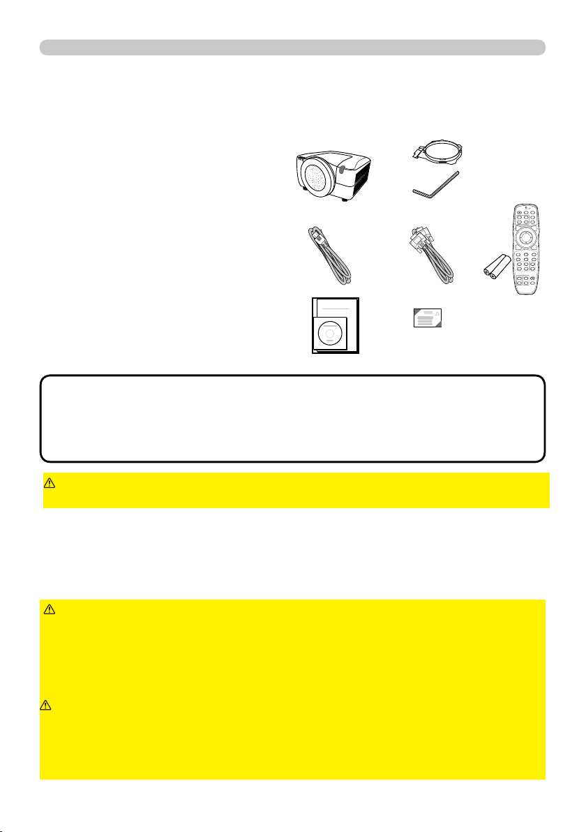
4
Introduction
(1) Projector
(2) Lens adapter
(3) Hexagon wrench (for installation of
the optional lens unit)
(4) Power cord
(5) Computer cable
(6) Remote control
with two batteries
(7) User’s manuals (a book and a CD)
(8) Security label
Soon after purchasing this product, check that all the following items are included in
the package. If any items should be missing, tell your dealer immediately.
►Use only the lens unit specifi ed by the manufacturer.
►Leave both attaching and removing the lens unit to the service personnel your
dealer sent.
►Read and keep the user’s manual of the lens unit.
►Use special caution not to drop the lens unit or knock it against something.
►Do not transport the projector to which the lens unit is attached.
WARNING
Keep the original packing materials for the lens unit, and use
them correctly when transporting or storing the lens unit.
CAUTION
►Do not touch the lens surface directly.
► Keep the dust protector of the projector, and use it while no lens unit is
attached to the projector.
NOTICE
• This product is supplied without a lens unit so that you can choose
from a range of lenses (
77 ) that can meet your requirements. Ask your dealer
about details, and prepare one or more lens unit together with this product.
• Some additional accessories or services may be required for your use. We
recommend consult with your dealer beforehand.
NOTE
►Keep the original packing materials, and use them correctly
when transporting or storing the product.
CAUTION
Request your dealer to install the lens unit in the projector. Be sure to leave both
removing and attaching the lens unit to the service personnel your dealer sent.
(1)
(2)
(3)
(8)
(4)
(7)
(6) (5)
BLANK LASER
FREEZE
LASER
INDICATOR
DIGITAL
STANDBY/ON COMPUTER
LENS SHIFT
KEYSTONE
ID 3
ID 4
ID 2
ID 1
VIDEO
AUTO
ASPECT
RESET
MENU
MAGNIFY
ON
OFF
3
4
ENTER
FOCUS
+
-
POSITION
PbyP
ZOOM
+
-
1
2
MY BUTTON
MY SOURCE
SHUTTER
Checking the contents of package
Attaching the lens unit
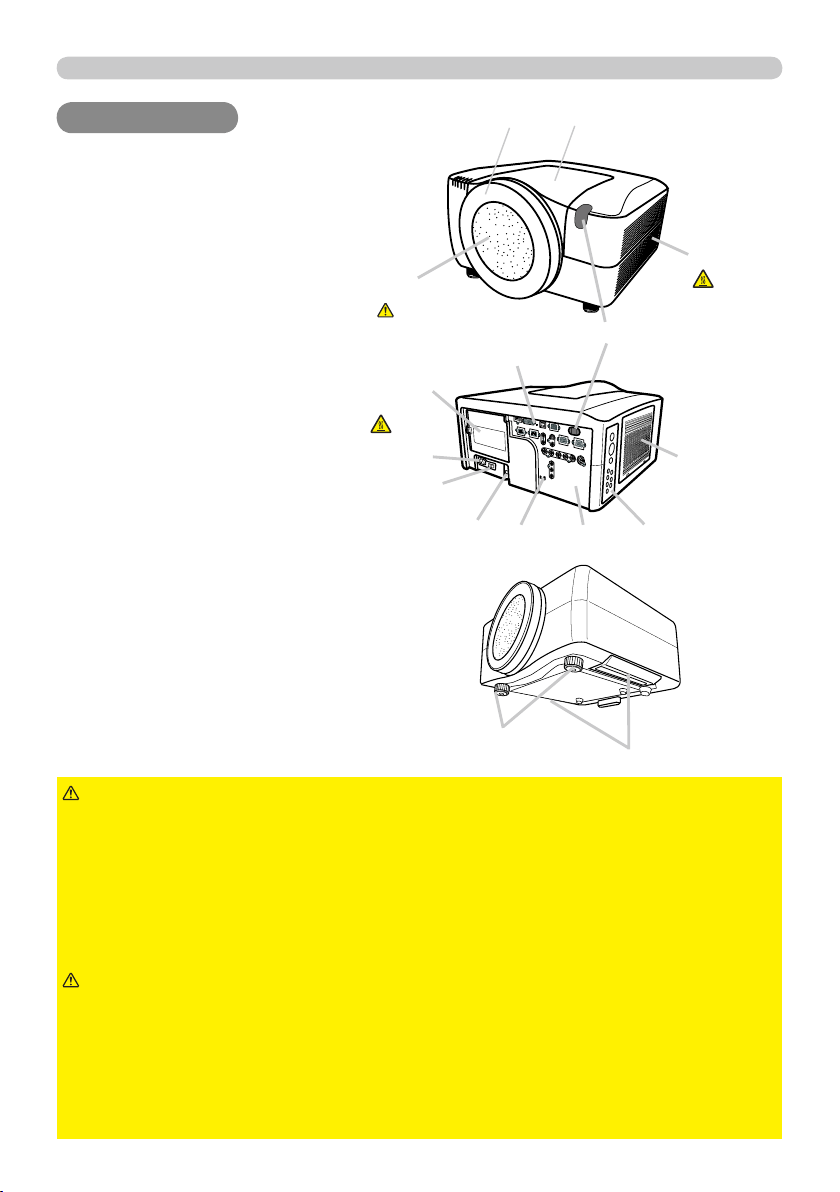
5
Part names
Part names
Part names
Projector
(1) Dust protector
(2) Remote sensors (x 2) (
17 )
(3) Exhaust vents
(4) Filter cover (
69 )
The fi lter unit and intake vent are
inside.
(5) Control panel (
6 )
(6) Rear panel (
6 )
(7) Shutdown switch (
73 )
(8) Lamp cover (
67 )
The lamp unit is inside.
(9)
AC IN
AC IN (AC inlet) (
15 )
(10) Power switch (
19,20 )
(11) Security bar (
10 )
(12) Security slot (
10 )
(13) Dented part (x 2) (
3 )
(14) Elevator feet (x 2) (
20 )
► HOT! : Do not touch around the lamp cover or the exhaust
vents during use or just after use, since it is hot.
►Do not look into the lens or vents while the lamp is on, since the strong light is
not good for your eyes.
►Do not grab the front cover or front ring to hold the projector, since you can
drop the projector.
►Do not handle the elevator feet without holding the projector, since the
projector may drop down.
WARNING
►Maintain normal ventilation to prevent the projector from
heating up. Do not cover, block or plug up the vents. Do not place anything that
can stick or be sucked to the vents, around the intake vents. Clean the air fi lter
periodically.
CAUTION
(2)
(3)
(8)
(10)
(9)
(12)
(14)
(4)
HOT!
(7)
(6)
(5)
(13)
(11)
(1)
HOT!
See the NOTICE
►Do not touch the lens surface directly.
► Keep the dust protector of the projector, and use it when no lens unit is
attached to the projector.
NOTICE
Front ring
Front cover
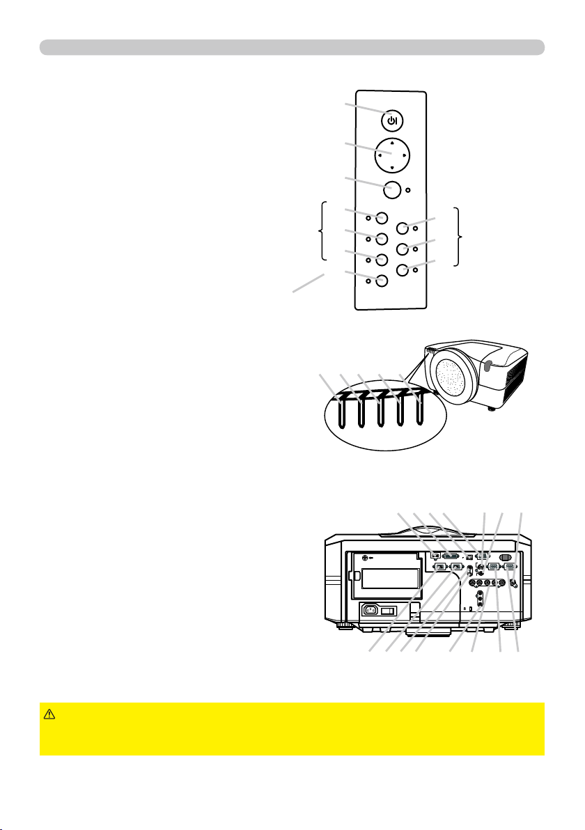
6
Part names
STANDBY/ON
MENU
LENS SHIFT
COMPUTER
ZOOM
VIDEO
FOCUS
DIGITAL
SHUTTER
I O
HDMI DVI-D
CONTROL IN CONTROL OUT
REMOTE
CONTROL
IN
OUT
S-VIDEO
COMPUTER IN2
COMPUTER IN1
VIDEO 1
BNC
R/Cr/Pr G/Y B/Cb/Pb H V VIDEO 2
Y
Cb/Pb
Cr/Pr
AC IN
LAN
MONITOR
OUT
Control panel
(1)
STANDBY/ON
STANDBY/ON button (
19,20 )
(2) Cursor buttons ( ▲/▼/◄/► ) (
28 )
(3)
MENU
MENU button (
28 )
(4)
COMPUTER
COMPUTER button (
22 )
(5)
VIDEO
VIDEO button (
22 )
(6)
DIGITAL
DIGITAL button (
22 )
(7)
LENS SHIFT
LENS SHIFT button (
21 )
(8)
ZOOM
ZOOM button (
21 )
(9)
FOCUS
FOCUS button (
21 )
(10)
SHUTTER
SHUTTER button (
26 )
Rear panel(
10 )
(1)
HDMI
HDMI port
(2)
DVI-D
DVI-D port
(3)
LAN
LAN port
(4)
MONITOR OUT
MONITOR OUT port
(5)
CONTROL IN
CONTROL IN port
(6)
CONTROL OUT
CONTROL OUT port
(7)
REMOTE CONTROL IN
REMOTE CONTROL IN port
(8)
REMOTE CONTROL OUT
REMOTE CONTROL OUT port
(9)
S-VIDEO
S-VIDEO port
(10)
VIDEO 1
VIDEO 1 port
(11)
VIDEO 2
VIDEO 2 port
(12)
COMPUTER IN1
COMPUTER IN1 port
(13)
COMPUTER IN2
COMPUTER IN2 port
(14)
BNC (G/Y, B/Cb
BNC (G/Y, B/Cb
/Pb
/Pb
, R/Cr
, R/Cr
/Pr
/Pr
, H, V)
, H, V) ports
(15) Component
(Y, Cb
(Y, Cb
/Pb
/Pb
, Cr
, Cr
/Pr
/Pr
)
) ports
(6)
(5)
(4)
(1)
(2)
(3)
►Use the shutdown switch only when the projector is not turned
off following the normal procedure, since pushing this switch stops operation of
the projector without cooling it down.
CAUTION
(1)
Indicator lamp (
72 )
(1)
POWER
POWER indicator
(2)
TEMP
TEMP indicator
(3)
LAMP
LAMP indicator
(4)
SECURITY
SECURITY indicator
(5)
SHUTTER
SHUTTER indicator
SHUTTERPOWER TEMP LAMP SECURITY
(9)
(8)
(7)
(10)
(1) (2) (3) (4) (5)
(2) (4)
(8) (7) (6) (5)
(3) (9) (10) (11)
(13) (12) (14) (15)
The indicator
will light in
green while
the menu of
the function is
displayed.
The
indicator of
group the
selected
input port
belongs to
will light in
green.
The indicator will blink in yellow
while the lens shutter is closed.

7
Part names
Remote control
(1) Laser pointer (
18 )
It is a beam outlet.
(2)
LASER INDICATOR
LASER INDICATOR (
18 )
(3)
LASER
LASER button (
18 )
(4)
STANDBY/ON
STANDBY/ON button (
19,20 )
(5)
ID
ID (
1-4
1-4) button (
18 )
(6)
COMPUTER
COMPUTER button (
22 )
(7)
VIDEO
VIDEO button (
22 )
(8)
DIGITAL
DIGITAL button (
22 )
(9)
MY SOURCE
MY SOURCE button (
22 )
(10)
LENS SHIFT
LENS SHIFT button (
21 )
(11)
ZOOM +/-
ZOOM +/- button (
21 )
(12)
FOCUS +/-
FOCUS +/- button (
21 )
(13)
AUTO
AUTO button (
23 )
(14)
POSITION
POSITION button (
24 )
(15)
ASPECT
ASPECT button (
23 )
(16)
KEYSTONE
KEYSTONE button (
24 )
(17)
MAGNIFY ON/OFF
MAGNIFY ON/OFF button (
25 )
(18)
FREEZE
FREEZE button (
25 )
(19)
BLANK
BLANK button (
26 )
(20)
SHUTTER
SHUTTER button (
26 )
(21)
MY BUTTON
MY BUTTON (
1-4
1-4) button (
49 )
(22)
P by P
P by P button (
27 )
(23)
MENU
MENU button (
28 )
(24)
ENTER
ENTER button : press the center point.
Cursor button: press the point ▲/▼/◄/► (
28 ).
(25)
RESET
RESET button (
28 )
(26) Wired remote control port (
18 )
(27) Battery cover (
16 )
(28) Battery holder (
16 )
(29) Frequency switch (
17 )
►Do not look into the beam outlet or
point the beam at people or pets while pressing the
LASER
LASER button, since the beam is not good for eyes.
WARNING
►Note that the laser beam may result
in hazardous radiation exposure. Use the laser pointer
only for pointing on the screen.
CAUTION
BLANK LASER
FREEZE
LASER
INDICATOR
DIGITAL
STANDBY/ON COMPUTER
LENS SHIFT
KEYSTONE
ID 3
ID 4
ID 2
ID 1
VIDEO
AUTO
ASPECT
RESET
MENU
MAGNIFY
ON
OFF
3
4
ENTER
FOCUS
+
-
POSITION
PbyP
ZOOM
+
-
1
2
MY BUTTON
MY SOURCE
SHUTTER
(4)
(2)
(1)
(3)
Back of
the remote control
(5)
(6)
(7)
(8)
(9)
(10)
(11)
(12)
(13)
(14)
(15)
(16)
(17)
(18)
(19)
(20)
(21)
(22)
(23)
(24)
(25)
(26)
(27)
(28)
(29)
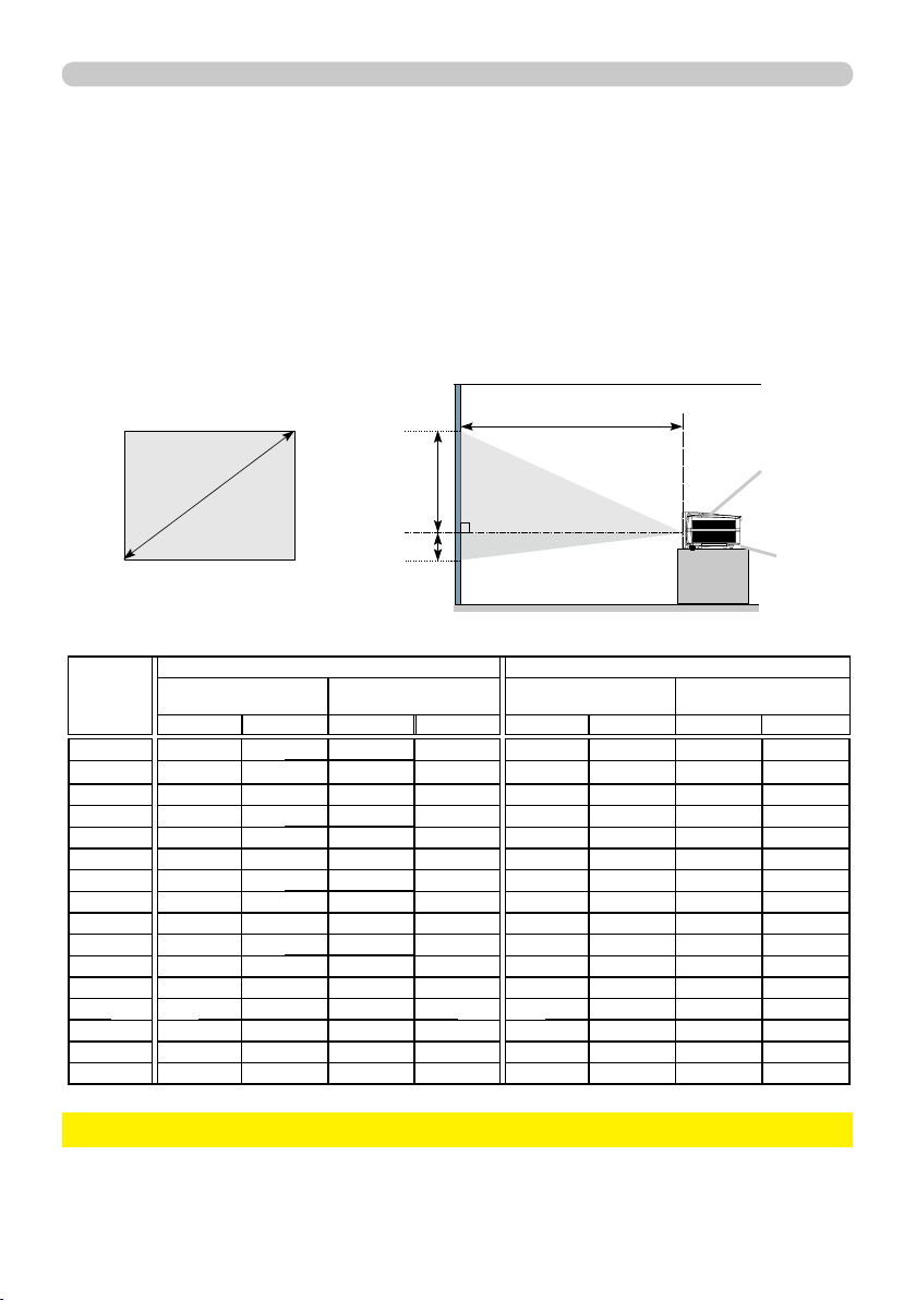
9
Setting up
Projection distance
Refer to the following to arrange the projector and your screen. The values shown in the
following table were calculated for the model CP-X10000 with the standard lens unit SD-
804. See the user’s manual of your lens unit for your case. The values differ for every
combination of the projector and the lens unit.
(a) Screen
size
[inch (m)]
4 : 3 screen 16 : 9 screen
(b) Projection distance
[m (inch)]
(c) Screen height
[cm (inch)]
(b) Projection distance
[m (inch)]
(c) Screen height
[cm (inch)]
min. max. down up min. max. down up
40 (1.0) 1.7 (66) 2.3 (89)
-23 (-9)
84 (33)
1.3 (53) 1.8 (72)
-33 (-13) 83 (33)
60 (1.5) 2.6 (103) 3.5 (136)
-34 (-13) 125 (49)
2.1 (83) 2.8 (110) -49 (-19) 124 (49)
70 (1.8) 3.1 (121) 4.0 (159)
-40 (-16)
146 (58) 2.5 (98) 3.3 (129) -58 (-23) 145 (57)
80 (2.0) 3.5 (139) 4.6 (183)
-45 (-18)
167 (66) 2.9 (112) 3.8 (148) -66 (-26) 165 (65)
90 (2.3) 4.0 (157) 5.2 (206)
-51 (-20)
188 (74) 3.2 (127) 4.3 (168) -74 (-29) 186 (73)
100 (2.5) 4.4 (175 5.8 (230)
-56 (-22)
209 (82) 3.6 (142) 4.7 (187) -82 (-32) 207 (81)
120 (3.0) 5.4 (211 7.0 (277)
-68 (-27)
251 (99) 4.4 (172) 5.7 (225) -99 (-39) 248 (98)
150 (3.8) 6.7 (266 8.8 (347)
-85 (-33)
313 (123) 5.5 (216) 7.2 (283) -123 (-49) 310 (122)
200 (5.1) 9.0 (356 11.8 (464)
-113 (-44)
418 (164) 7.4 (290) 9.6 (379) -164 (-65) 414 (163)
250 (6.4) 11.3 (447 14.8 (582)
-141 (-56)
522 (206) 9.2 (364) 12.0 (474) -206 (-81) 517 (204)
300 (7.6) 13.6 (537 17.8 (699)
-169 (-67)
627 (247) 11.1 (438) 14.5 (570) -247 (-97) 620 (244)
350 (8.9) 15.9 (628 20.7 (816)
-198 (-78)
731
(288) 13.0 (512) 16.9 (666)
-288 (-113) 724 (285)
400 (10.2) 18.2 (718 23.7 (934)
-226 (-89)
835 (329) 14.9 (586) 19.4 (762) -329 (-130) 827 (326)
500 (12.7) 22.8 (899 29.7 (1168)
-282 (-111)
1044 (411) 18.6 (734) 24.2 (954) -411 (-162) 1034 (407)
600 (15.2) 27.4 (1081 35.6 (1403)
-339 (-133)
1253
(493)
22.4 (882) 29.1 (1145) -493 (-194) 1241 (488)
700 (17.8) 32.0 (1262 41.6 (1638)
-395 (-156)
1462 (576) 26.2 (1030) 34.0 (1337) -576 (-227) 1447 (570)
(a)
(b)
(c) up
(c) down
* The values shown in the table are calculated for a full size screen: 1024×768
(a) Screen size (diagonal)
(b) Projection distance (±10%)
(c) Screen height (±10%), when the vertical lens shift is set full upward.
Projector top
Projector bottom
(Installation side)
►Do not use a polarized screen, since it can cause a red image. NOTICE
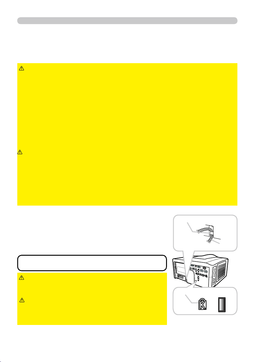
10
Setting up
Supplementary anti-theft means
This projector has the security bar for a commercial
anti-theft chain or wire up to 10 mm in diameter, and
also the security slot for the Kensington lock.
For details, see the manual of your security tool.
►Do not use the security slot to
prevent the projector from falling down, since it is not
designed for it.
WARNING
•
These are not provided as comprehensive theft
preventions but supplemental measures.
NOTE
Security slot
Anti-theft chain or wire
Security bar
►Keep the projector away from anything that is easy to catch
fi re.
►Do not block or cover the openings on the projector, and keep suffi ciently
space for ventilation around the projector.
• Do not use the projector on a cushiony surface such a rug, a carpet or bedding.
• Keep the projector away from any light materials such as a piece of paper that
can stick to the intake holes.
►Do not use the projector on an unstable stand such as a cart.
►Place the projector so that nothing enters to the inside of the projector.
• Keep the projector away from any small things such as paperclips that can fall
into the inside.
• Keep the projector away from any liquids that can spill or leak into the product.
WARNING
►Keep the projector away from anything that is heat conductive
such as metal.
• Do not use the projector on a metallic table.
►Keep the projector away from anything that is weak in heat such as some kinds
of plastics.
CAUTION
►Place the projector so that there is nothing that blocks the
projection light to the screen.
► Avoid exposing directly the remote sensor to any strong lights.
NOTICE
Placement
►Do not place the anti-theft chain
or wire near the projector’s exhaust vents, since the
chain or wire heated by the hot exhaust gas may
cause burns.
CAUTION
In placing the projector in place in accordance with the preceding section
"Projection distance" (
9 ) heed the following too.

11
Setting up
Connecting with your devices
Before connecting the projector to your devices, check the manual of the device in
order to make sure that the device is suitable to connect with this projector and to
check what is required for the connection.
Consult your dealer when the required accessory did not come with the product or
the accessory is damaged. It may be regulated under some standard.
►Use only the accessories specifi ed or recommended by
manufacturer. Modify neither a projector nor accessories.
►Do not connect or disconnect the projector with devices while they are
connected to a power supply except for the cases directed by the manuals of
devices.
WARNING
►Some connecting cable may have to have a specifi c length,
or a ferrite core at the end to connect to the projector, under the regulation of
electro-magnetic interference. When a ferrite core is attached to the specifi ed
cable only at one end, connect to the projector the end that the ferrite core is
attached at.
►Be careful not to set a connector into a wrong port or with a wrong way.
►Be careful not to damage the cables. Route the cables not to be stepped on
and pinched out.
CAUTION
(continued on next page)
• For this product, the optional cable cover is ready to be purchased. To
place an order for it, please tell your dealer the type name of it (
77 ).
NOTE
After making sure that the projector and the devices are turned off, perform
the connection, according to the following instructions. Refer to the fi gures in
subsequent pages.
►Do not turn your device on prior to the projector, except for the
cases directed by the manuals of devices.
NOTICE
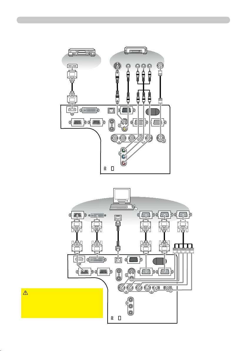
12
Setting up
Control from the computer
HDMI
REMOTE
CONTROL
LAN
DVI-D
CONTROL IN CONTROL OUT
IN
OUT
S-VIDEO
VIDEO 1
COMPUTER IN1 COMPUTER IN2
MONITOR
OUT
BNC
VIDEO 2
R/Cr/Pr G/Y B/Cb/Pb H V
Y
Cb/Pb
Cr/Pr
K
HDMI
S-VIDEO
OUT
VIDEO
OUT
COMPONENT
Y Cb/Pb Cr/Pr
VIDEO
OUT
(continued on next page)
Connecting your devices (continued)
Example of connecting with VCR or DVD players
HDMI
REMOTE
CONTROL
LAN
DVI-D
CONTROL IN CONTROL OUT
IN
OUT
S-VIDEO
VIDEO 1
COMPUTER IN1 COMPUTER IN2
MONITOR
OUT
BNC
VIDEO 2
R/Cr/Pr G/Y B/Cb/Pb H V
Y
Cb/Pb
Cr/Pr
K
DVI-D
RS-232C
RGB OUT
RGB OUT RGB OUT
LAN
Example of connecting with computers
►For safety,
do not connect the
LAN
LAN port
to any network that might
have excessive voltage.
CAUTION
Digital signal input
Video signal input
Computer signal input

13
Setting up
Connecting your devices (continued)
Example of connecting with another projector or a display device
HDMI
REMOTE
CONTROL
LAN
DVI-D
CONTROL IN CONTROL OUT
IN
OUT
S-VIDEO
VIDEO 1
COMPUTER IN1 COMPUTER IN2
MONITOR
OUT
BNC
VIDEO 2
R/Cr/Pr G/Y B/Cb/Pb H V
Y
Cb/Pb
Cr/Pr
K
RS-232C
RGB OUT
BLANK LASER
FREEZE
LASER
IND
ICATOR
DIGITAL
STANDBY/
ON
COMPUTER
LENS SHIFT
KEYSTONE
ID 3
ID 4
ID 2
ID 1
VIDEO
AUTO
ASPECT
RESET
MENU
MAGNIFY
ON
OFF
3
4
ENTER
FOCUS
+
-
POSITION
PbyP
ZOOM
+
-
1
2
MY BUTTON
MY SOURCE
SHUTTER
REMOTE
CONTROL IN
RS-232C
RGB IN
Control from the computer
Redirection
of an RGB input
to another display
Simultaneous remote control
of another projector
Control of
another device by
RS-232C commands
Computer signal input
Wired
remote
control
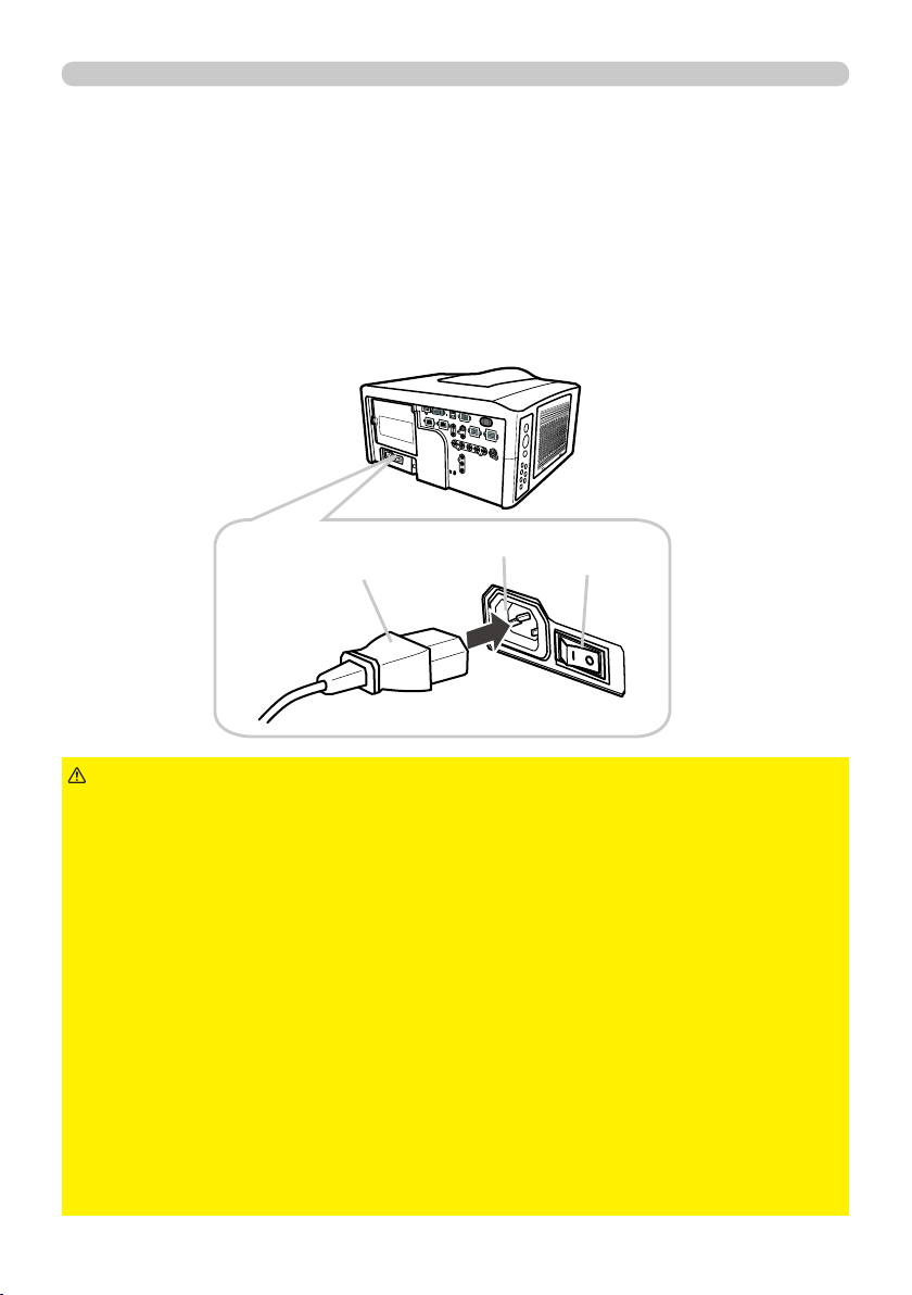
15
Setting up
Connecting power supply
1.
Make sure that the power switch of the projector is set to the off-position
(marked with “
O
O”).
2.
Insert the socket end of the power cord into the
AC IN
AC IN (AC inlet) of the
projector.
►Do not connect the projector to a power supply when the lens
unit is not attached.
►Use this projector from only the specifi ed power supply in accordance with the
label indication on the projector.
►Use a power outlet that is close to the projector and easily accessible.
►Do not overload the outlet, since overloading can result in a fi re or an electric
shock.
►Use only the power cord that came with this product and is suitable for your
power supply. If the suitable power cord did not come with this product, consult
your dealer.
►Do not use a damaged power cord. If the power cord you need is damaged,
ask your dealer for a new power cord of the same type.
►Do not handle the power cord with wet hands.
►Do not repair or modify the power cord.
►Be careful not to damage the power cord. Route the power cord so that it is
not likely to be walked on or pinched by items placed upon or against them.
►Connect fi rmly the power cord not to result in loose connection. Do not use a
loose or unsound power outlet.
WARNING
AC IN
AC IN
Socket of the power cord
In accordance with the warnings shown below, connect the AC inlet of the
projector to the proper power outlet. The following walks you through the
connection.
3.
Plug the other end of the power cord into the power outlet.
Power switch

16
Remote control
Remote control
Remote control
Putting batteries
The remote control needs the two batteries of the following type.
1.
Remove the battery cover in the back of the
remote control. Push lightly the knob of the
battery cover while pulling it up.
2.
Put the batteries into the battery holder, according to the
polarity markings “+” and “-“ inside the holder.
3.
Put the battery cover back into place until it clicks.
►Be careful not to press the
LASER
LASER button when loading the
batteries. It is dangerous if a laser beam is unintentionally turned on. Please
refer to the section "Laser pointer" (
18).
►Be careful of handling batteries, since a battery can cause explosion, cracking
or leakage that could result in a fi re, injury, or environment pollution.
•
Use only the specifi ed batteries. Do not use batteries of different types.
• When replacing, replace both of the batteries with new batteries of the same
type. Do not use a new battery with a used battery.
•
Do not use a battery with damage, such as scratches, dents, rust or leakage.
• Make sure the plus and minus terminals are correctly aligned when loading a
battery.
• Do not work on a battery; for example recharging or soldering.
• If the remote control is not used for a long period of time, remove the batteries.
• Keep batteries in a dark, cool and dry place. Never expose a battery to a fi re or
water.
• Keep batteries away from children and pets.
• When a battery leaked, wipe the leakage out well with a waste cloth. If the
leakage adhered to your body, immediately rinse it well with water. When a
battery leaked in the battery holder, replace the batteries after wiping the leakage
out.
• Obey the local laws on disposing a battery.
WARNING
HITACHI MAXELL, part number LR6 or R6P
The batteries that came with the product are a type suitable to this remote control.
The following walks you through loading batteries into the remote control.
• If the remote control malfunctions, try replacing the batteries with
fresh ones.
NOTE
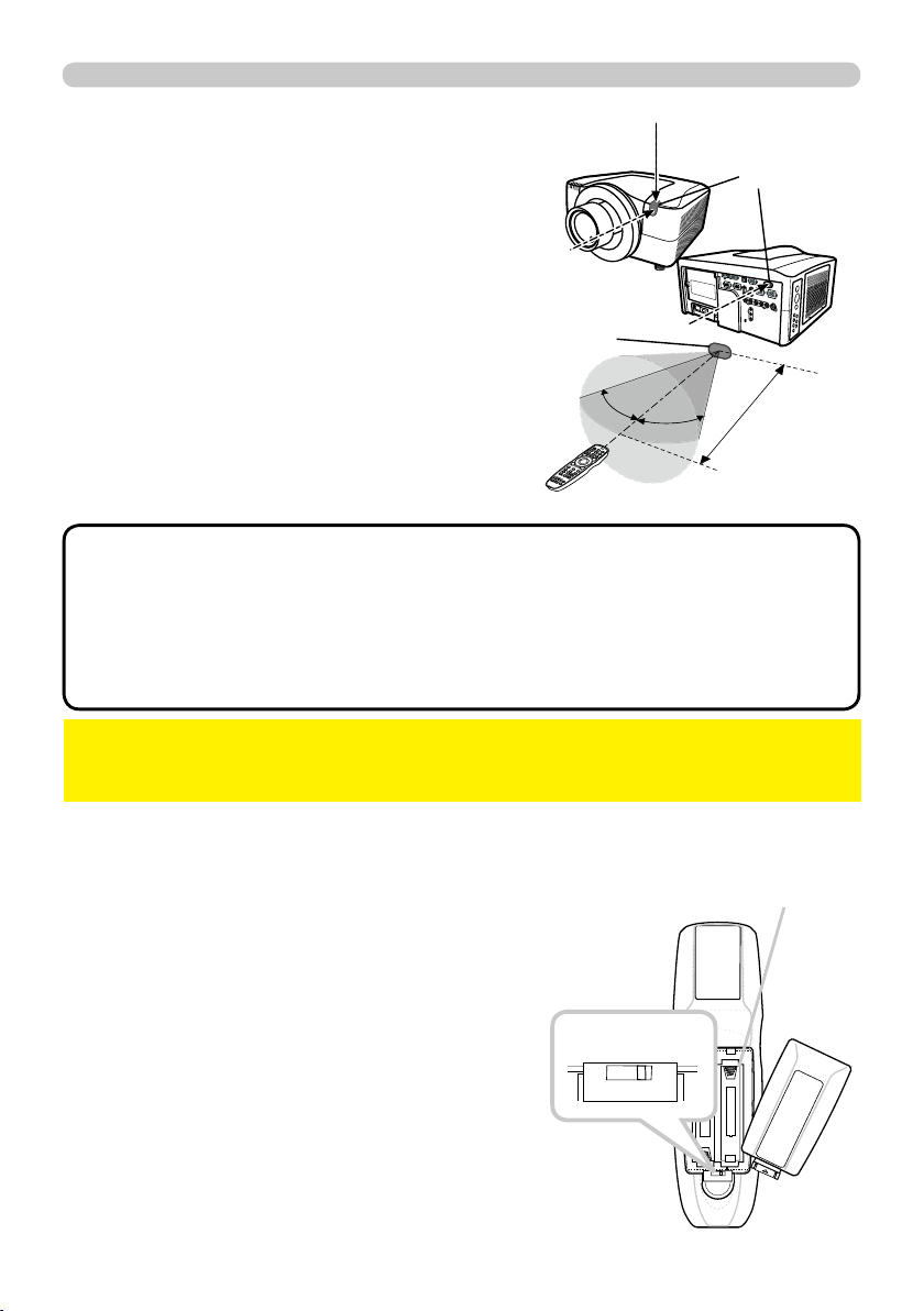
17
Remote control
BLANK LASER
FREEZE
LASER
INDICATO
R
DIGITAL
STANDBY/ON
COMPUTER
LENS SHIFT
KEYSTONE
ID 3
ID 4
ID 2
ID 1
VIDEO
AUTO
ASPECT
RESET
MENU
MAGNIFY
ON
OFF
3
4
ENTER
FOCUS
+
-
POSITION
PbyP
ZOOM
+
-
1
2
MY BUTTON
MY SOURCE
SHUTTER
Transmitting condition
The remote control works with the remote
sensors on the projector using infrared light
(Class 1 LED). The remote sensor senses the
remote control signals reached into the range
within 60 degrees (to right and left) and 3 meters
about from the sensor.
30º
30º
Approx.
3 m
Remote
sensor
Remote
sensors
• You can inactivate one or two sensors from the three sensors using
the item REMOTE RECEIVE. of the SERVICE menu under the OPTION menu.
• When you want to use two or more projectors of this type at the same time
and the same place, utilize the REMOTE ID function. The buttons of
ID 1
ID 1,
ID 2
ID 2,
ID 3
ID 3 and
ID 4
ID 4 on the remote control can name the projector given the same ID
number as the button by the item REMOTE ID of the SERVICE menu under the
OPTION menu.
NOTE
►Avoid exposing directly the remote sensor to any strong lights.
►Do not put anything between the remote control and the remote sensor on the
projector, since it may interfere with transmission of the remote control signals.
NOTICE
Changing the frequency of remote control signal
The accessory remote control has the choice of
mode 1 or mode 2, in the frequency of its signal.
If the remote control does not function properly,
attempt to change the signal frequency.
Please remember that the “REMOTE FREQ.” in
SERVICE item of OPTION menu (
51 ) of the
projector to be controlled should be set to the
same mode as the remote control.
To set the mode of the remote control, slide the
knob of the frequency switch inside the battery
cover into the position indicated by the mode
number to choose.
2 1
Back of the
remote control
Inside of
the battery cover
Frequency switch
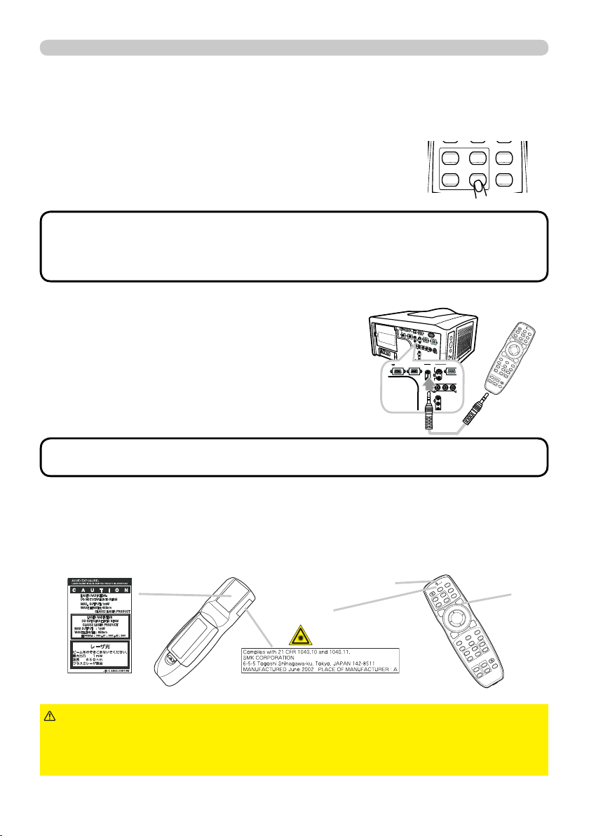
18
Remote control
BLANK LASER
FREEZE
LASER
INDICATOR
DIGITAL
STANDBY/ON COMPUTER
LENS SHIFT
KEYSTONE
ID 3
ID 4
ID 2
ID 1
VIDEO
AUTO
ASPECT
RESET
MENU
MAGNIFY
ON
OFF
3
4
ENTER
FOCUS
+
-
POSITION
PbyP
ZOOM
+
-
1
2
MY BUTTON
MY SOURCE
SHUTTER
Using as a wired remote control
The accessory remote control works as a wired remote control,
when the wired control port at the bottom of the remote control
connects with the
REMOTE CONTROL
REMOTE CONTROL port on the back of the
projector via an audio cable with 3.5 diameter stereo mini plugs.
This function is useful when a wireless remote signal
may not reliably reach the projector.
• To connect the remote control with the projector, use an audio cable
with 3.5 diameter stereo mini plugs.
NOTE
MI DVI
-
D
CONTROL IN CONTROL OUT
REMOTE
CONTROL
IN
OUT
S-VIDEO
COMPUTER
VIDEO 1
BNC
R/Cr/Pr G/Y B/Cb/Pb H
Y
Cb/Pb
Cr/Pr
MONITOR
OUT
BLANK LASER
FREEZE
LASER
INDICATOR
DIGITAL
STANDBY/ON COMPUTER
LENS SHIFT
KEYSTONE
ID 3
ID 4
ID 2
ID 1
VIDEO
AUTO
ASPECT
RESET
MENU
MAGNIFY
ON
OFF
3
4
ENTER
FOCUS
+
-
POSITION
PbyP
ZOOM
+
-
1
2
MY BUTTON
MY SOURCE
SHUTTER
Laser pointer
This remote control has a laser pointer in place of a fi nger or rod. The laser beam
works and the
LASER INDICATOR
LASER INDICATOR lights while the
LASER
LASER button is pressed.
►Use the laser beam of the remote control only for the pointer
on the screen. Do not apply the laser beam to anything except the screen.
• Never hit eyes by the laser beam since the laser beam can injure eyes.
• Do not apply the laser beam to anything except the screen.
WARNING
LASER INDICATOR
LASER INDICATOR
LASER
LASER button
Laser aperture
Using the REMOTE ID function
This is the function to defi ne which projector is controlled by the remote control. Utilize
this function when you use some projectors of the same type at the same time.
1.
Set the ID number to the projector beforehand,
referring to the item “REMOTE ID” item (
52 ).
2.
Press a ID button on the remote control. The ID button
selected will light for 3 seconds.
• Each time you press any button (except ID buttons), the ID button of
current selected ID number will light.
• To confi rm the projector's current ID, press any ID button for 3 seconds. Its
number will be shown on each screen regardless of set ID of projector.
NOTE
DIGITAL
ID 3
ID 4
ID 2
ID 1
VIDEO

20
Operating
1.
Turning off
2.
Press the
STANDBY/ON
STANDBY/ON button again while the
message is shown.
The projector lamp will go off, and the
POWER
POWER
indicator will begin blinking in orange.
Then the
POWER
POWER indicator will stop blinking
and light in steady orange when lamp cooling is
complete.
3.
After making sure that the
POWER
POWER indicator lights in steady orange, and
press down the side marled “
O
O” on the power switch.
The
POWER
POWER indicator will go off.
• Use the shutdown switch only when the projector can be not turned
off by normal procedure.
NOTE
►Do not approach the lamp cover and the exhaust vents for a
while after the lamp goes out, since they may be hot and could cause burns.
WARNING
►Turn your device off prior to the projector, except for the cases
directed by the manuals of devices.
NOTICE
The following walks you through the steps to turn the projector off.
For other devices, follow the manual of each.
Press the
STANDBY/ON
STANDBY/ON button on the projector
or the remote control.
The message "Power off?" will appear on the
screen for about 5 seconds.
STANDBY/ON
SHUTTERSECURITYLAMPTEMPPOWER
STANDBY/ON
Using the elevator feet
Lengthening or shortening the length of the elevator feet shifts the projection
position and the projection angle.
Turn the elevator feet each to adjust their length
►Do not place the projector with an inclination of 5 degrees
or more. The projector leaned exceeding the limit could cause malfunction and
shorten the life of the projector .
CAUTION
5°
►Do not lengthen the elevator feet to 30 mm or more. The foot
lengthened exceeding the limit may come off and drop the projector down, and
result in an injury or damaging the projector.
WARNING
max.
30 mm
Power
switch
POWER
POWER indicator
STANDBY/ON
STANDBY/ON button

21
Operating
Using the functions for the lens
ZOOM / FOCUS
Press the
ZOOM
ZOOM /
FOCUS
FOCUS
button. The ZOOM / FOCUS
dialog will appear. Adjust the zoom / focus using the◄/►
button while the dialog is displayed. Press the ▼ button to
select "EXIT" on the dialog. It fi nishes the OSD menu.
LENS SHIFT
Press the
LENS SHIFT
LENS SHIFT button. The LENS SHIFT
dialog will appear. Using the ▲/▼/◄/► buttons
while the dialog is displayed shifts the lens.
In the LENS SHIFT dialog:
Press the
DIGITAL
DIGITAL button.
In the standby mode:
Press the
LENS SHIFT
LENS SHIFT and the
DIGITAL
DIGITAL
buttons for 3 seconds at the same time.
CENTERING
● While the lens is shifting, the menu will disappears and the icon of hourglass will
appears on screen. Shifting may takes some time. Depending on the case, it
may reach one minute.
● The LENS SHIFT indicator lights up or blinks in green while the lens is shifting.
Then the indicator will stop blinking and light for 3 seconds in steady green
when the centering is complete.
● When the lens is located in the center already, pressing the
DIGITAL
DIGITAL button in
the LENS SHIFT dialog lights in steady green the LENS SHIFT indicator for 3
seconds.
LENS MEMORY SAVE / LOAD / CLEAR
This projector is equipped with memory functions for the lens adjustments (zoom,
focus and shift).
To display the LENS MEMORY dialog, select the LENS MEMORY on the ZOOM,
FOCUS or LENS SHIFT dialog. Then the LENS MEMORY dialog will appear.
SAVE: To save the current lens adjustments,
select a SAVE-(1-3) and press ► or
ENTER
ENTER
button.
LOAD: To load a saved adjustments, select the
LOAD-(1-3) and press ► or
ENTER
ENTER button.
When the
MY BUTTON
MY BUTTON button is allocated to
the LOAD-(1-3) the memory can be loaded
without the LENS MEMORY dialog.
CLEAR: Selecting the CLEAR LENS MEMORY in the LENS MEMORY dialog
displays CLEAR LENS MEMORY dialog. Select the number to be cleared
using ▲/▼ buttons and press the ► button. The dialog to check your intention
will come out. Then press the ► button again in the dialog.
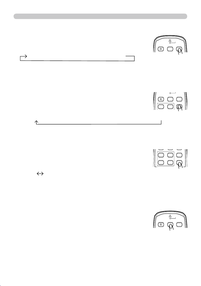
22
Operating
1.
1.
Press the
VIDEO
VIDEO button to select an input for video signal.
Each time you press the button, the projector switches its
video input port as below.
Press the
DIGITAL
DIGITAL button to select an input for digital signal.
Each time you press the button, the projector switches its
digital input port as below.
● While ON is selected for AUTO SEARCH item in OPTION menu, the projector
will keep checking every port sequentially till an input signal is detected (
47
).
If
VIDEO
VIDEO button is pushed when
COMPUTER IN1
COMPUTER IN1 or
COMPUTER IN2
COMPUTER IN2 port is
selected, the projector will check Component port fi rst.
● While ON is selected for AUTO SEARCH item in OPTION menu, the projector
will keep checking every port sequentially till an input signal is detected (
47
).
If
DIGITAL
DIGITAL button is pushed when Component,
S-VIDEO
S-VIDEO,
VIDEO 1
VIDEO 1 or
VIDEO 2
VIDEO 2
port is selected, the projector will check
HDMI
HDMI port fi rst.
COMPONENT (Y, Cb /Pb , Cr /Pr ) S-VIDEO VIDEO 1 VIDEO 2
HDMI
DVI-D
1.
Press the
MY SOURCE
MY SOURCE button on the remote control. The
input signal will be changed into the signal you set as MY
SOURCE(
49 ).
● This function also can use for document camera. Select the input port that
connected the document camera.
LASER
INDICATOR
STANDBY/ON COMPUTER
MY SOURCE
Displaying and switching the image
COMPUTER IN1 COMPUTER IN2 BNC
1.
Press the
COMPUTER
COMPUTER button to select an input port for the
RGB signal.
Each time you press the button, the projector switches its
RGB input port from the current port as below.
●
While ON is selected for AUTO SEARCH item in OPTION menu, the
projector will keep checking every port sequentially till an input signal is
detected
(
47)
. If
COMPUTER
COMPUTER button is pushed when
VIDEO 1
VIDEO 1,
VIDEO
VIDEO
2
2,
S-VIDEO
S-VIDEO,
Component
,
HDMI
HDMI or
DVI-D
DVI-D port is selected, the projector will
check
COMPUTER IN1
COMPUTER IN1 port fi rst.
STANDBY/ON COMPUTER
ID 3ID 1
VIDEO
MY SOURCE
DIGITAL
ID 3
ID 4
ID 2
ID 1
VIDEO
LASER
INDICATOR
STANDBY/ON COMPUTER
VIDEO
MY SOURCE

23
Operating
1.
Press the
AUTO
AUTO button on the remote control.
Pressing this button performs the following.
Using the automatic adjustment feature
For a computer signal
The vertical position, the horizontal position and the
horizontal phase will be automatically adjusted.
Make sure that the application window is set to its
maximum size prior to attempting to use this feature.
A dark picture may still be incorrectly adjusted. Use a
bright picture when adjusting.
For a video signal and s-video signal
The video format best suited for the respective input signal will be selected
automatically. This function is available only when the AUTO is selected for
the VIDEO FORMAT item in the INPUT menu (
37 ). The vertical position
and horizontal position will be automatically set to the default.
For a component video signal
The vertical position, horizontal position and horizontal phase will be
automatically set to the default.
● The automatic adjustment operation requires approx. 10 seconds. Also
please note that it may not function correctly with some input. When this
function is performed for a video signal, a certain extra such as a line may
appear outside a picture.
● The items adjusted by this function may vary when the FINE or DISABLE is
selected for the AUTO ADJUST item of the SERVICE item in the OPTION
menu (
50 ).
1.
Press the
ASPECT
ASPECT button on the remote control.
Each time you press the button, the projector switches the mode for aspect
ratio in turn.
Selecting an aspect ratio
●
*
16:10 / FULL: CP-WX11000 only. NATIVE: Except
CP-X10000. SMALL: Except CP-WX11000.
● The NORMAL mode keeps the original aspect ratio of
the signal.
For a computer signal
NORMAL 4:3 16:9 16:10
*
SMALL
*
NATIVE
*
FULL
*
For an HDMI or DVI-D signal
NORMAL 4:3 16:9 16:10
*
14:9 SMALL
*
NATIVE
*
FULL
*
For a video signal, s-video signal or component video signal
4:3 16:9 16:10
*
14:9 SMALL
*
NATIVE
*
FULL
*
For no signal
4:3 (fi xed, except CP-WX11000) / FULL (fi xed,
CP-WX11000)
FREEZE
ASPECT
RESET
MENU
ENTER
SHUTTER
BLANK LASER
LASER
INDICATOR
DIGITAL
STANDBY/ON COMPUTER
ID 3
ID 4
ID 2
ID 1
VIDEO
MY SOURCE
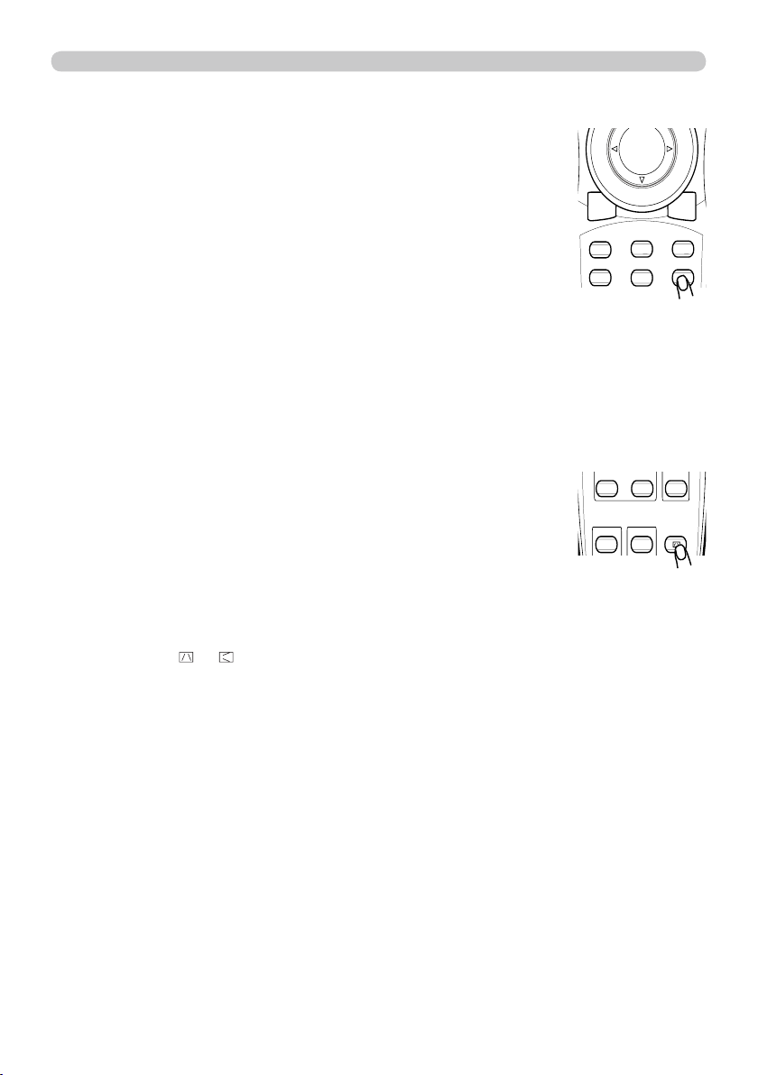
24
Operating
1.
Press the
POSITION
POSITION button on the remote control when no
menu is indicated.
The “POSITION” indication will appear on the screen.
Adjusting the position
2.
Use the
▲/▼/◄/►
cursor buttons to adjust the picture position.
When you want to reset the operation, press the
RESET
RESET
button on the remote control during the operation.
To complete this operation, press the
POSITION
POSITION button
again. Even if you do not do anything, the dialog will
automatically disappear after a few seconds.
●
When this function is performed on a video signal, s-video signal or component
video signal, some image such as an extra-line may appear at outside of the picture.
●
When this function is performing on a Video signal, S-Video signal, or component
signal of 480i@60 or 576i@50 input the range of this adjustment depends on the
OVER SCAN in IMAGE menu (
34 ). It is not possible to adjust when the OVER
SCAN is set to 10.
1.
Press the
KEYSTONE
KEYSTONE button on the remote
control. A dialog will appear on the screen
to aid you in correcting the distortion.
Correcting the keystone distortion
2.
Use the ▲/▼ cursor buttons to select AUTO or MANUAL
operation, and press the ► button to perform the following.
● The adjustable range of this function will vary among inputs. For some input, this
function may not work well.
● When V:INVERT or H&V:INVERT is selected to the MIRROR item in the SETUP
menu, if the projector screen is inclined or angled downward, this function may
not work correctly.
● When the zoom adjustment is set to the TELE (telephoto focus), this function
may be excessive. This function should be used when the zoom adjustment is
set to the full WIDE (wide-angle focus) whenever possible.
● When the projector is placed on the level (about ±3°), this function may not work.
●
When the projector is inclined to near ±30 degree or over, this function may not work well.
● When the vertical lens shift is not set fully upward (not set fully downward for the
optional lens type USL-801 only (
51 )), this function may not work well.
●
When the horizontal lens shift is not set to the center, this function may not work well.
● This function will be unavailable when Transition Detector is on (
64 ).
1) AUTO executes automatic vertical keystone correction.
2) MANUAL displays a dialog for keystone correction.
Use the ▲/▼ cursor buttons to select the direction to
correct ( or ) then use the ◄/► buttons for adjustment.
To close the dialog and complete this operation, press the
KEYSTONE
KEYSTONE button
again. Even if you don’t do anything, the dialog will automatically disappear
after a few seconds.
FREEZE
AUTO
ASPECT
RESET
MENU
ENTER
POSITION
PbyP
SHUTTER
KEYSTONE
OFF
4
FOCUS
+
ZOOM
+
2

25
Operating
• The zoom level can be fi nely adjusted. Closely watch the screen to
fi nd the level you want.
NOTE
1.
Press the
ON
ON button of
MAGNIFY
MAGNIFY on the remote control.
The “MAGNIFY” indication will appear on the screen and
the projector will go into the MAGNIFY mode. In the Magnify
mode, the picture will be zoomed. The indication will
disappear in several seconds with no operation.
Using the magnify feature
2.
Use the ▲/▼ cursor buttons to adjust the zoom level. To move the zoom
area, press the
POSITION
POSITION button in the MAGNIFY mode, then use the
▲/▼/◄/► cursor buttons to move the area. And to fi nalize the zoom area,
press the
POSITION
POSITION button again.
To exit from the MAGNIFY mode and restore the screen to normal, press the
OFF
OFF button of
MAGNIFY
MAGNIFY on the remote control.
● The projector automatically exits from the MAGNIFY mode when the input
signal is changed or when the display condition is changed.
● In the MAGNIFY mode, the keystone distortion condition may vary, it will be
restored when the projector exits from the MAGNIFY mode.
1.
Press the
FREEZE
FREEZE button on the remote control.
The “FREEZE” indication will appear on the screen (however,
the indication will not appear when the OFF is selected for
the MESSAGE item in the SCREEN menu (
45 )), and the
projector will go into the FREEZE mode, which the picture is
frozen.
To exit the FREEZE mode and restore the screen to normal,
press the
FREEZE
FREEZE button again.
Temporarily freezing the screen
● The projector automatically exits from the FREEZE mode when some control
buttons are pressed.
● If the projector continues projecting a still image for a long time, the LCD
panel might possibly be burned in. Do not leave the projector in the FREEZE
mode for too long.
AUTO
MAGNIFY
ON
OFF
3
4
POSITION
PbyP
1
2
MY BUTTON
BLANK LASER
FREEZE
MENU
ENTER