180615
NOTE:
Please read all
instructions carefully
before using this product
Table of Contents
Safety Notice
Important Assembly
Information
Care and Maintenance
Parts List
Warranty
Ordering Parts
Model
MD-9010G
Retai
n This
M
anual
f
or
Referenc
e
OWNE
R'S
MANUA
L
MARCY
®
DIAMOND ELITE
SMITH MACHINE
MD-9010G
IMP
ORTANT:
Please read this manual before commencing
assembly of this product.
IMPEX
®
INC.
2801 S. Towne Ave, Pomona, CA 91766
Tel: 800- 999-8899
www.marcypro.com
support@impex-fitness.com

TABLE OF CON
TENTS
BEFORE YOU BEGIN....................................................................................………… 1
IMPORTANT SAFETY NOTICES...................................................................……….. 2
EXERCISE GUIDELINES…………………………………………………………………. 3
WARNING LABEL PLACEMENT.....….....................................................................… 5
FREE AND TRAINING AREA……………………………………………………………….6
I MPORTANT ASSEMBLY INFORMATION.................................................................7
CABLE ASSEMBLY INSTRUCTION……………………………………………………….9
WEIGHT CAPACITY AND DIMENSION………..…………………………………………18
CARE AND MAINTENANCE………………………………………………………………..18
OPERATING NOTES………………………………………………………………………..19
WEIGHT RESISTANCE CHART…………………………………………………………….20
SMITH MACHINE PARTS LIST……………………………………………………………..21
SMITH MACHINE EXPLODED DIAGRAM………………………………………………...24
BENCH PARTS LIST…………………………………………………………………………25
BENCH EXPLODED DIAGRAM.…………………………………………………………....26
WARRANTY.................................................................................................…………...27
ORDERING PARTS.......................................................................................………….27
BEFORE YO
U BEGIN
Thank y ou f
or s electing MARCY SMITH MACHINE MD-9010G by IMPEX
®
INC. F
or your safety and benefit, read this manual carefully before using the
equipment. A s a m anufacturer, w e a re committed to providing you with
complete customer satisfaction. If you have any questions, or find there are
missing or damaged parts, we guarantee you complete satisfaction through
direct assistance from our factory. To avoid unnecessary delays, please call
our TOLL-FREE customer service number. O ur C ustomer S ervice A gents
will provide immediate assistance.
Toll-F
ree Customer Service Number
1-800-999-8899
Mon. – Fri. 9 a.m. – 5 p.m. PST
www.marcypro.com
suppor
t@impex-fitness.com
©IMPEX INC.
1
www.marcypro.com

IMPORTANT S
AFETY NOTICE
This exercise equipment is built for optimum safety. However, certain precautions apply
whenever you operate a piece of exercise equipment. Be sure to read the entire manual
before you assemble or operate your equipment. In particular, note the following safety
precautions:
1. Keep children and pets away from the equipment at all times. DO NOT
leave children unattended in the same room with the equipment.
2. Only one person at a time should use the equipment.
3. If the user experiences dizziness, nausea, chest pain, or any other abnormal
symptoms, STOP the workout at once. CONSULT A PHYSICIAN
IMMEDIATELY.
4. Position the equipment on a clear, leveled surface. DO NOT use the equipment
near water or outdoors.
5. Keep hands away from all moving parts.
6. Always wear appropriate workout clothing when exercising. DO NOT wear
robes or other clothing that could become caught in the equipment. Running
or aerobic shoes are also required when using the equipment.
7. Use the equipment only for its intended use as described in this manual.
DO NOT use attachments not recommended by the manufacturer.
8. Do not place any sharp object around the equipment.
9. Disabled persons should not use the equipment.
10. Before using the equipment to exercise, always do stretching exercises to
properly warm up.
11. Never operate the equipment if the equipment is not functioning properly.
12. A spotter is recommended during exercise.
13. This equipment is designed and intended for home and consumer use only, not for
commercial use.
WARNING: BEFORE BEGINNING ANY EXERCISE PROGRAM, CONSULT YOUR
PHYSICIAN. THIS IS ESPECIALLY IMPORTANT FOR INDIVIDUALS OVER THE AGE
OF 35 OR PERSONS WITH PRE-EXISTING HEALTH PROBLEMS. READ ALL
INSTRUCTIONS BEFORE USING ANY FITNESS EQUIPMENT. IMPEX INC. ASSUMES
NO RESPONSIBILITY FOR PERSONAL INJURY OR PROPERTY DAMAGE
SUSTAINED BY OR THROUGH THE USE OF THIS PRODUCT.
SAVE THESE INSTRUCTIONS.
©IMPEX INC.
2
www.marcypro.com

EXECISE GUIDEL
INES
Building Muscle and Gaining Weight
Unlike aerobic exercise, which emphasizes endurance training, anaerobic exercise focuses on
strength training. A gradual weight gain can occur while building the size and strength of muscles.
While developing muscle mass, your body adapts to the stress placed upon it. You can modify your
diet to include foods such as meat, fish and vegetables. These foods help muscles recover and
replenish important nutrients after a strenuous workout.
Muscle Strength and Endurance
To achieve the greatest benefit from exercise, it is important to develop an exercise program that
allows you to work all of the major muscle groups equally.
To increase muscle strength, follow this principle:
Increasing resistance and maintaining the number of repetitions of an exercise results in increased
muscle strength.
To tone your body, follow this principle: Decreasing resistance plus increasing the number of
repetitions of an exercise results in increased body tone.
Once you feel comfortable with an exercise, you can change the resistance, the number of
repetitions, or the speed at which you do the exercise. It is not necessary to change all three
variables. For example, let’s say that you are training at 23 kg (50 lb.) and performing the exercise 10
times in 3 minutes. When this becomes too easy, you may decide to move up to lifting 27 kg (60 lb.)
for the same number of repetitions in the same amount of time. Lifting more weights fewer times
most often develops muscle strength. To gain both muscle strength and endurance, it is
recommended that you perform each exercise 15 to 20 reps per set.
Training Intensity
How hard you begin to train depends on your overall level of fitness. The soreness you experienced
can be lessened by decreasing the load you place on your muscles and by performing fewer sets. To
avoid injury, you should gradually work into an exercise program and set the load to your individual
fitness level. The load should increase as your fitness level increases.
Muscle soreness is common, especially when you first start exercising. If you are painfully sore for a
long time, it may be time to change your program. Eventually, your muscle system will become
accustomed to the stress and strain placed on it.
©IMPEX INC.
3
www.marcypro.com

Beginning a St
rength Building Program
Warming Up
To begin strength training, it is important to stretch and perform light exercise for 5 to 10 minutes.
This helps prepare the body for more strenuous exercise by increasing circulation, raising your body
temperature and developing more oxygen to your muscles.
Workout
For each workout, to keep in mind that muscle soreness that lasts for a long period is not desirable
and may mean that injury has occurred.
Cool Down
At the end of each workout, perform slow stretching exercises for 5 to 10 minutes. Ease into each
stretch only going as far as you can. This stage allows your muscles to wind down after training.
To provide a total workout program it is also recommended that 2 to 3 days of aerobic exercise is
performed in addition to the strength training.
Drinking Water
For the body to function properly, it must be properly hydrated. If you are exercising, you should
increase your fluid intake. The reason for this is that the water you take in will leave your system
through the sweating mechanism that cools your body during exercise. The water you lose through
exercise must be replaced so that the muscles can recover properly.
Rest Day
Although you may not feel like doing it, taking a rest day at least once a week is important because it
gives your body a chance to heal it self. Continuously working your muscles will result in over-
training, which will not benefit you in the long run.
©IMPEX INC.
4
www.marcypro.com
WARNING LABEL P
LACEMENT
The war
ning labels shown here have been placed on the Cross Brace, Rear Stabilizer, and Upper Frame. If the
labels are missing or illegible, please call customer service at 1-800-888-8899 for replacements. Apply the labels
in the location shown.
©IMPEX INC.
5
www.marcypro.com
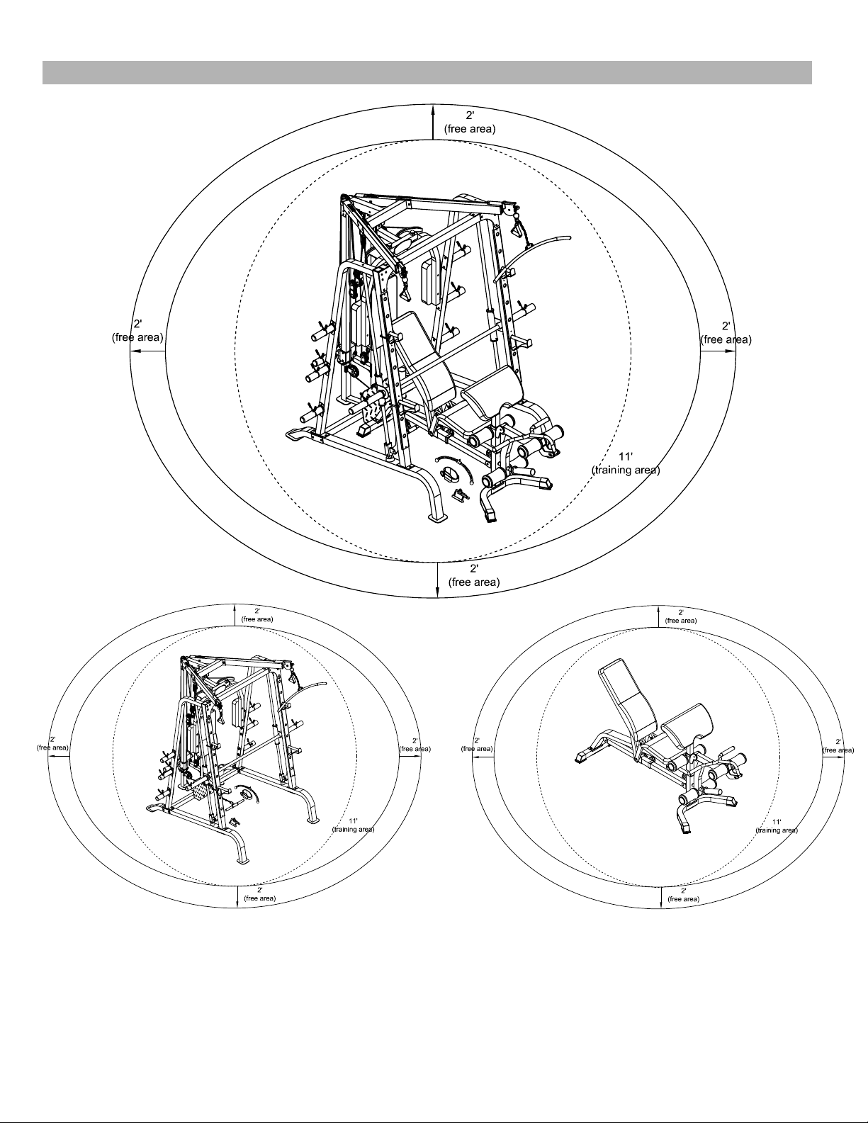
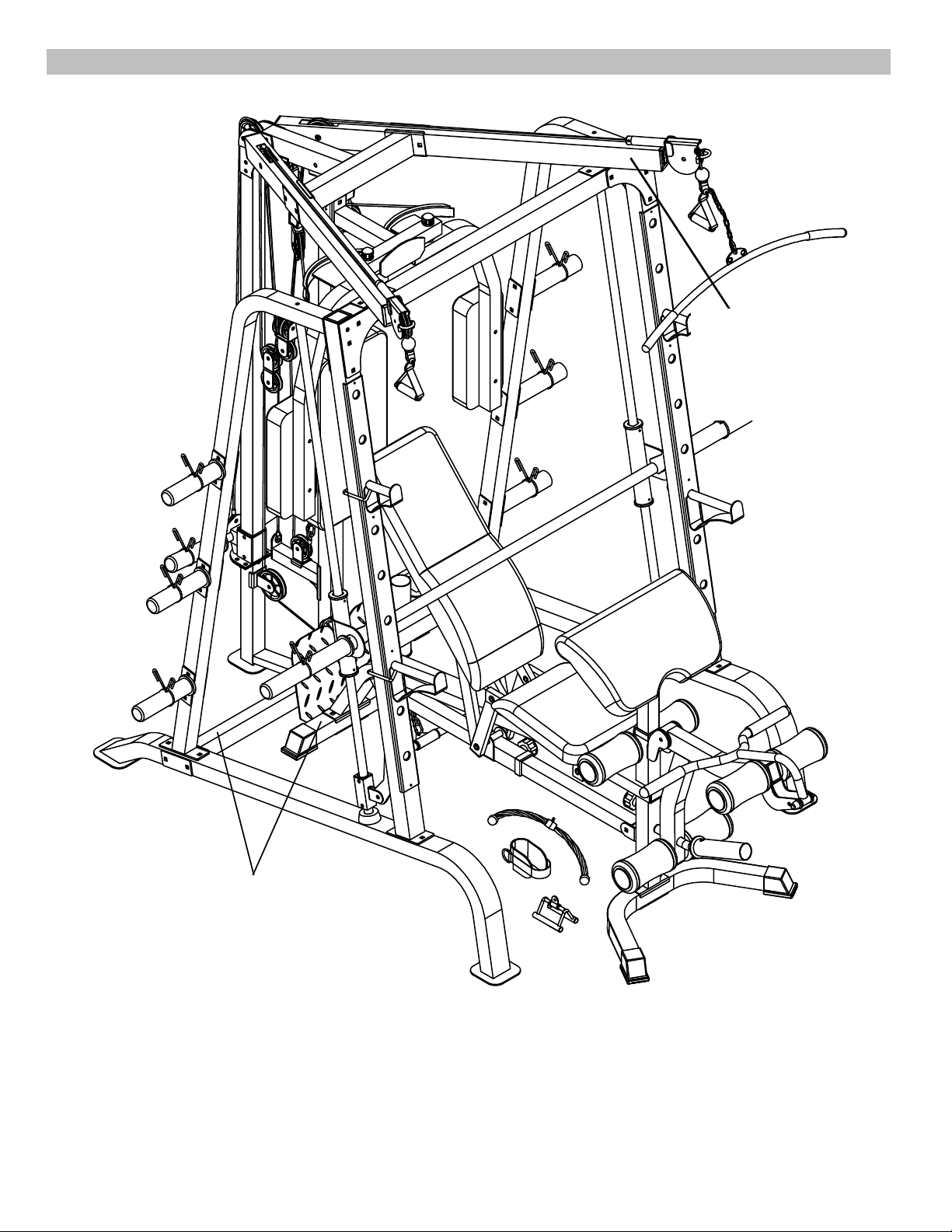
FREE AND TRAINI
NG AREA
©IMPEX INC.
6
www.marcypro.com

IMPORTANT A
SSEMBLY INFORMATION
Tools required for assembling the bench: Two adjustable Wrenches and Allen wrenches.
NOTE: It is strongly recommended that this equipment be assembled by two or more
people to avoid possible injury.
Ensure Carriage Bolts are inserted through the SQUARE holes on components that need to
be assembled. Attach washer only to end of the Carriage Bolt.
Use Allen Bolts or Hex Bolts inserted through the ROUND hole on components that need to
be assembled.
Always wait until all bolts are assembled onto the bench before tightening the bolts. Do not
tighten each bolt right after it is installed
Fasten Nut
s and Bolts
Securely tighten all nuts and bolts after all
components have been assembled in current and
previous steps.
NOTE: Do not over-tighten any component with
pivoting function.
Make sure all pivoting components are able to move
freely.
Do not tighten all nuts and bolts in this step.
Inspect a
nd ensure all bolts and Nuts are fastened after the equipment is
completely assembled.
Assemble with correct Hardware Pack
Only use the hardware packs marked “For Smith Machine” to assemble Smith Machine.
Only use the hardware packs marked “For Bench” to assemble Bench.
Tools
Tools required for assembling this equipment: Allen Wrenches (provided by manufacturer), and
Adjustable Wrench, or Socket Wrench, or Ratchet Wrench.
NOTE: It is strongly recommended that this machine be assembled and moved by two or
more people to avoid possible injury.
©IMPEX INC.
7
www.marcypro.com

Assemble Sliding Weight Post in assembly Step-6
The triangular bracket on the Sliding Weight Post (Part #14) must be facing up and toward to back.
Weight Bar A
ssembly Note
NOTE: Help of another person is strongly recommended for this step. Place the Lifting Sleeve (#27)
in between the two Safety Stop Frames (#26). Align the holes. Insert the Weight Bar (#28) into the
Safety Stop Frame from one end and through the Lifting Sleeve (#27) to the other Safety Stop Frame
on the opposite side. Secure the Weight Bar to each Safety Stop Frame with two M8 x 3/8” Allen
Bolts (#81) on each Safety Stop Frame. Ensure the Bolts are fastened so the Weight Bar won’t slide
through the Safety Stop Frame.
©IMPEX INC.
8
www.marcypro.com
SMITH MACHI
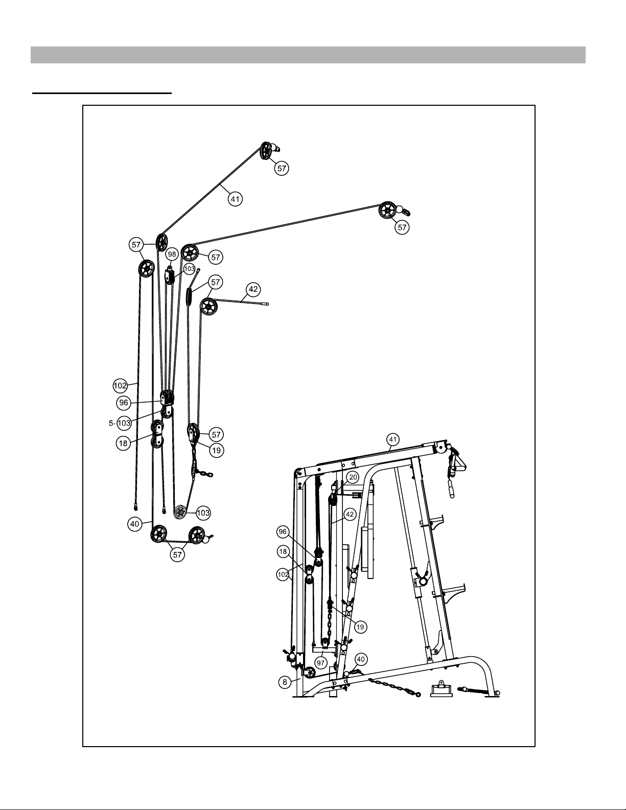
NE CABLE ASSEMBLY INSTRUCTION
Cable Loop Diagr
am
©IMPEX INC.
9
www.marcypro.com
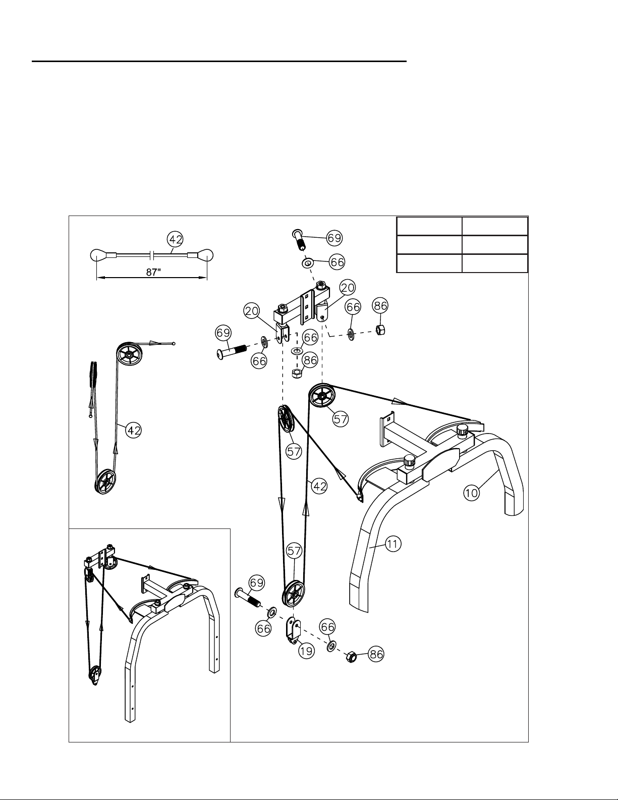
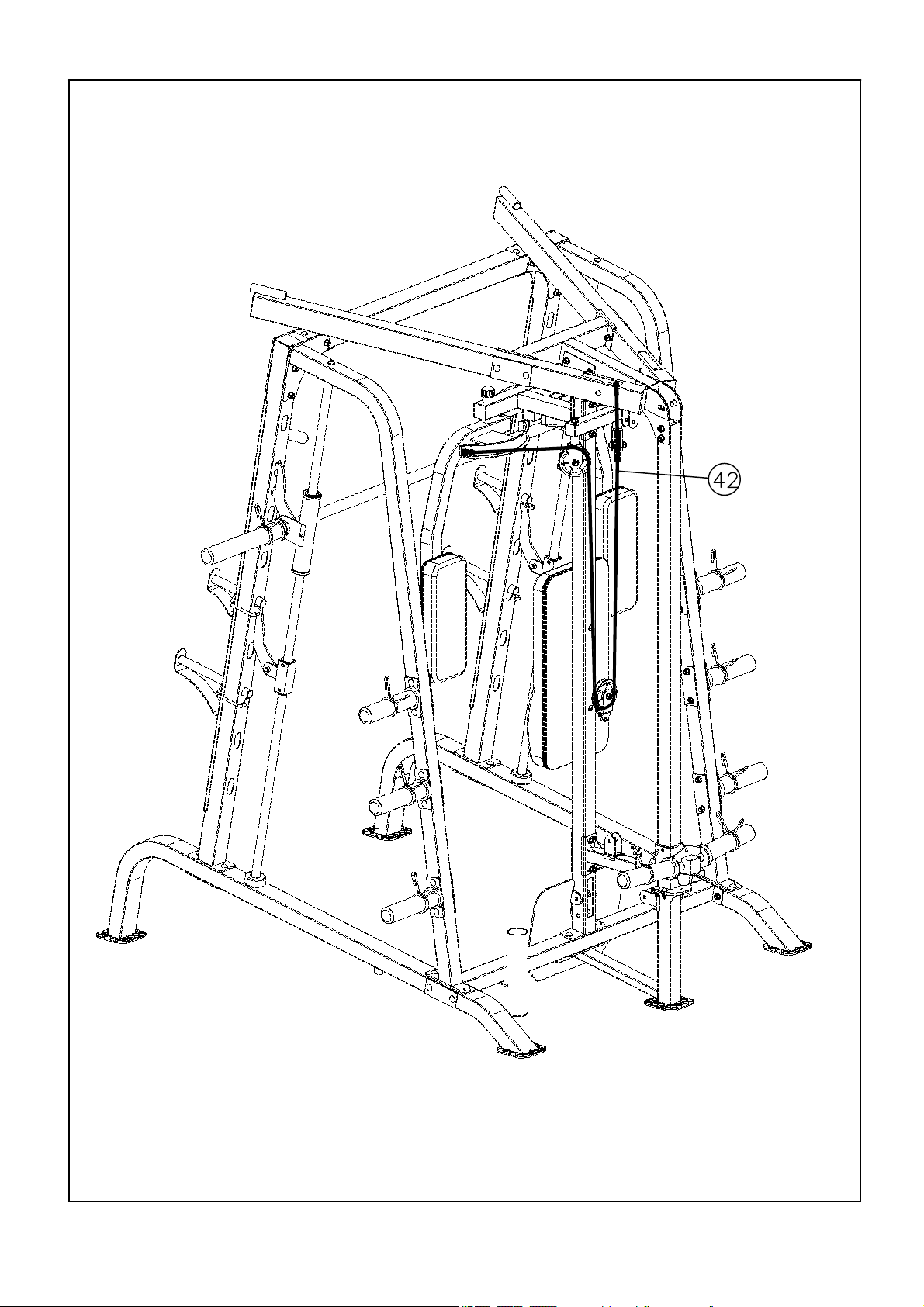
, Step-12A
12Butterfly Ca
ble assembly instruction Step-
A.) Attach one end of 87” Butterfly Cable (#42) to the clip on Right Butterfly (#11). Draw the Cable to
the right Swivel Pulley Bracket (#20).
B.) Attach a Pulley (#57) to the Bracket. Secure it with one M10 x 1 ¾” Allen Bolt (#69), two Ø ¾”
Washer s (#66), and one M10 Aircraft Nut (#86).
C.) Draw the Cable around the Pulley then downward. Attach a Single Floating Pulley Bracket (#19)
to the Cable. Repeat Procedure B above to install a Pulley. Let the Bracket hanging for now.
D.) Draw the Cable around the Pulley then upward to the left Swivel Pulley Bracket. Repeat
Procedure B above to install a Pulley to the Bracket.
E.) Draw the Cable around the Pulley then clip to the Left Butterfly (#10).
12
#19 BOX 2
#42 BOX 2
#57 BOX 2
©IMPEX INC.
10
www.marcypro.com
12-A
©IMPEX INC.
11
www.marcypro.com

,Step-13B
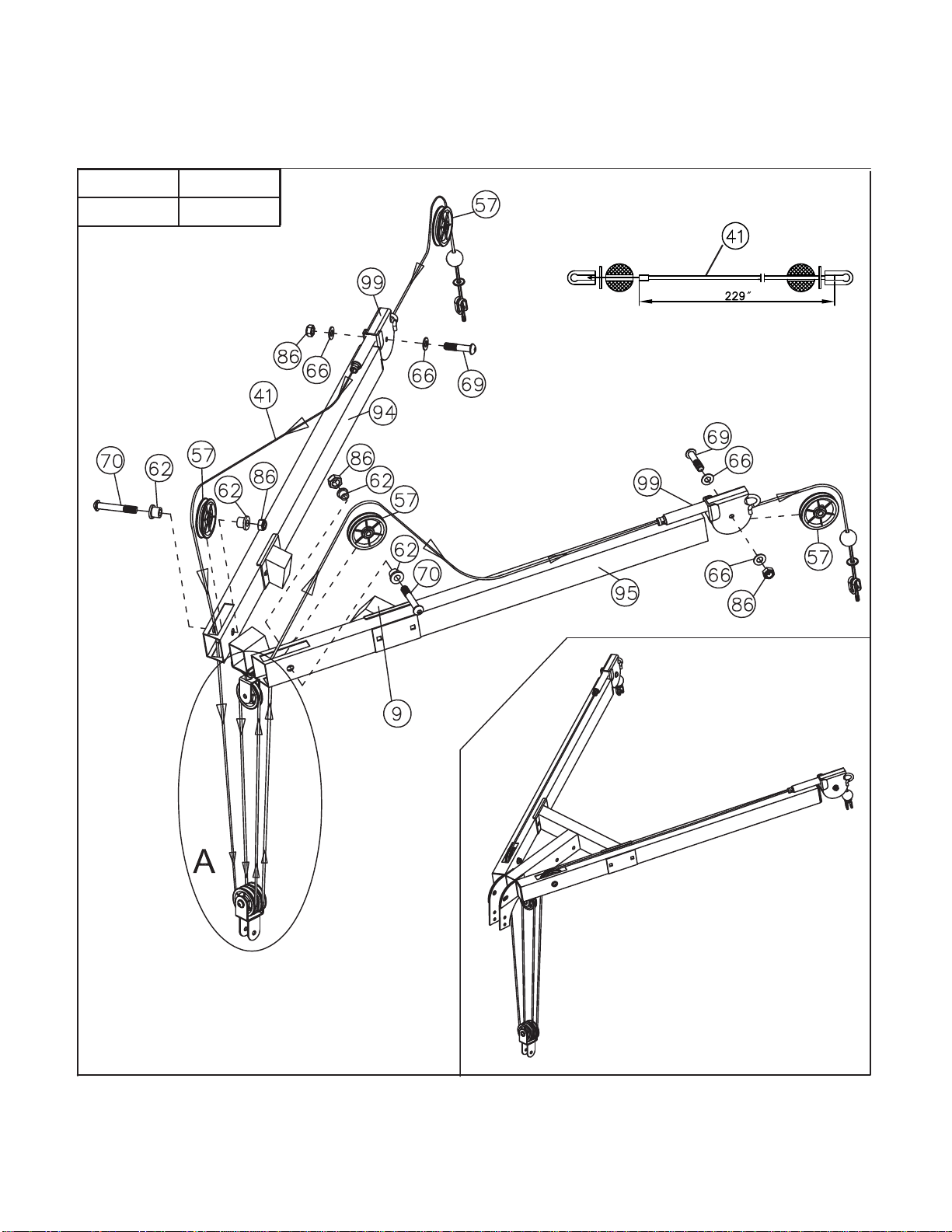
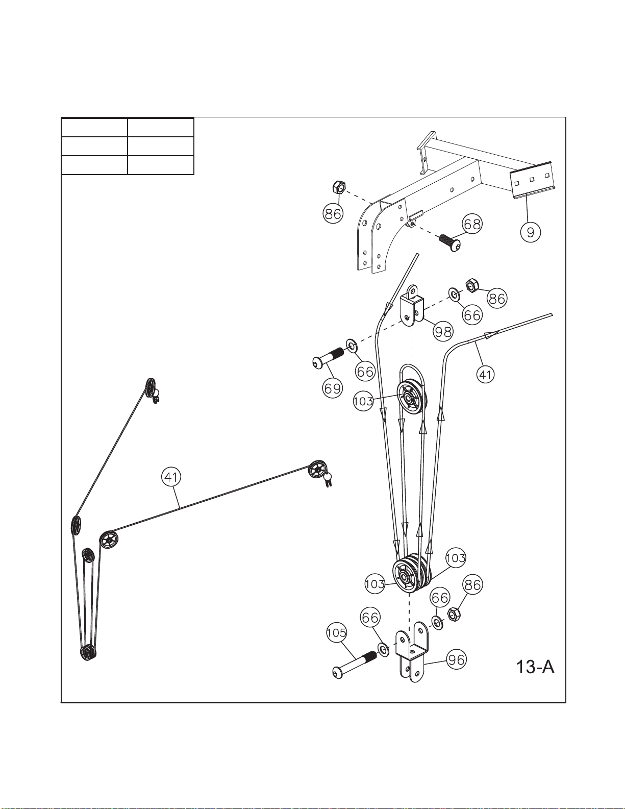
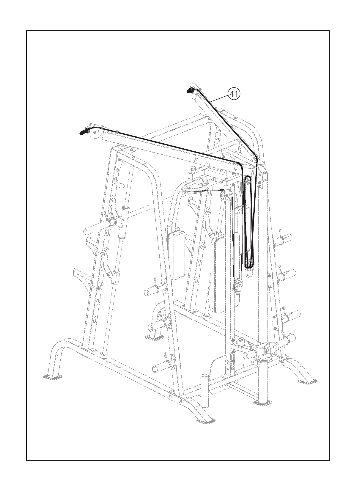
3A3,Upper Cable assembly instruction Step-1 Step-1
A.) Remove the U-shaped Connector, Big Washer, and Ball Stopper from one end of the
229“Upper Cable (#41).
B.) Insert this End through the left Cross-over Swivel Pulley Bracket (#99). Attach a Pulley (#57)
to the Swivel Bracket and secure it with one M10 x 1 ¾” Allen Bolt (#69), two Ø ¾” Washers
(#66), and one M10 Aircraft Nut (#86). Draw the Cable over the Pulley and pull it toward the
back of the machine.
C.) Draw the Cable along the Left Upper Frame (#94) to the opening on the rear of the Left Upper
Frame. Drop the Cable through the opening.
D.) Attach a Pulley to the opening. Secure it with one M10 x 2 ½” Allen Bolt (#70), two Pulley
Bushings (#62), and one M10 Aircraft Nut (#86). Draw the Cable around the Pulley then
downward.
E.) Attach a Single Small Pulley Bracket (#98) to the bracket underneath the Rear Upper Frame
(#9). Secure it with one M10 x 1” Allen Bolt (#68) and one M10 Aircraft Nut (#86).
F.) Attach two Small Pulleys (#103) to the Triple Floating Pulley Bracket (#96). Secure them with
one M10 x 2 ¾” Allen Bolts (#105), two Ø ¾” Washers (#66), and one M10 Aircraft Nut (#86).
Draw the Cable around the front Small Pulley (closer to Butterfly) then upward to the Single
Small Pulley Bracket (#98) installed in Procedure E. Attach a Small Pulley (#103) to the Small
Pulley Bracket (#98). Secure the Small Pulley with one M10 x 1 ¾” Allen Bolt (#69), two Ø ¾”
Washers (#66), and one M10 Aircraft Nut (#86).
G.) Draw the Cable around the Small Pulley then downward to the Triple Floating Pulley Bracket.
Draw the Cable around the Small Pulley (closer to the Sliding Weight Post) then upward to the
opening on the rear of Right Upper Frame (#95). Let the Triple Floating Pulley Bracket
hanging for now.
H.) Attach a Pulley to opening on the rear of Right Upper Frame. Secure it with one M10 x 2 ½”
Allen Bolt (#70), two Pulley Bushings (#62), and one M10 Aircraft Nut (#86). Draw the Cable
over the Pulley along the top of the right Cross-over Swivel Pulley Bracket. Attach a Pulley
(#57) to the Swivel Bracket and secure it with one M10 x 1 ¾” Allen Bolt (#69), two Ø ¾”
Washers (#66), and one M10 Aircraft Nut (#86).
I.) Re-install the Ball Stopper, Big Washer, and the U-shaped Connector removed in Procedure A
above. Secure this end and the other end of Cable with one M10 x 1 ⅛ ” Allen Bolt (#104) and
one M10 Aircraft Nut (#86).
J.) Connect a Single Handle Strap (#90) to each end of the Cable with a C-clip (#61).
K.) When using the Lat Bar (#29), remove one of the Single Handle Strap and connect the Lat Bar
to the Cable end with a Short Chain (#63) and two C-Clips.
©IMPEX INC.
12
www.marcypro.com
13
#41 BOX 2
#57 BOX 2
©IMPEX INC.
13
www.marcypro.com
#96 BOX 2
#98 BOX 2
#103 BOX 2
©IMPEX INC.
14
www.marcypro.com
13-B
©IMPEX INC.
15
www.marcypro.com

A
4aA
,Step-1
1
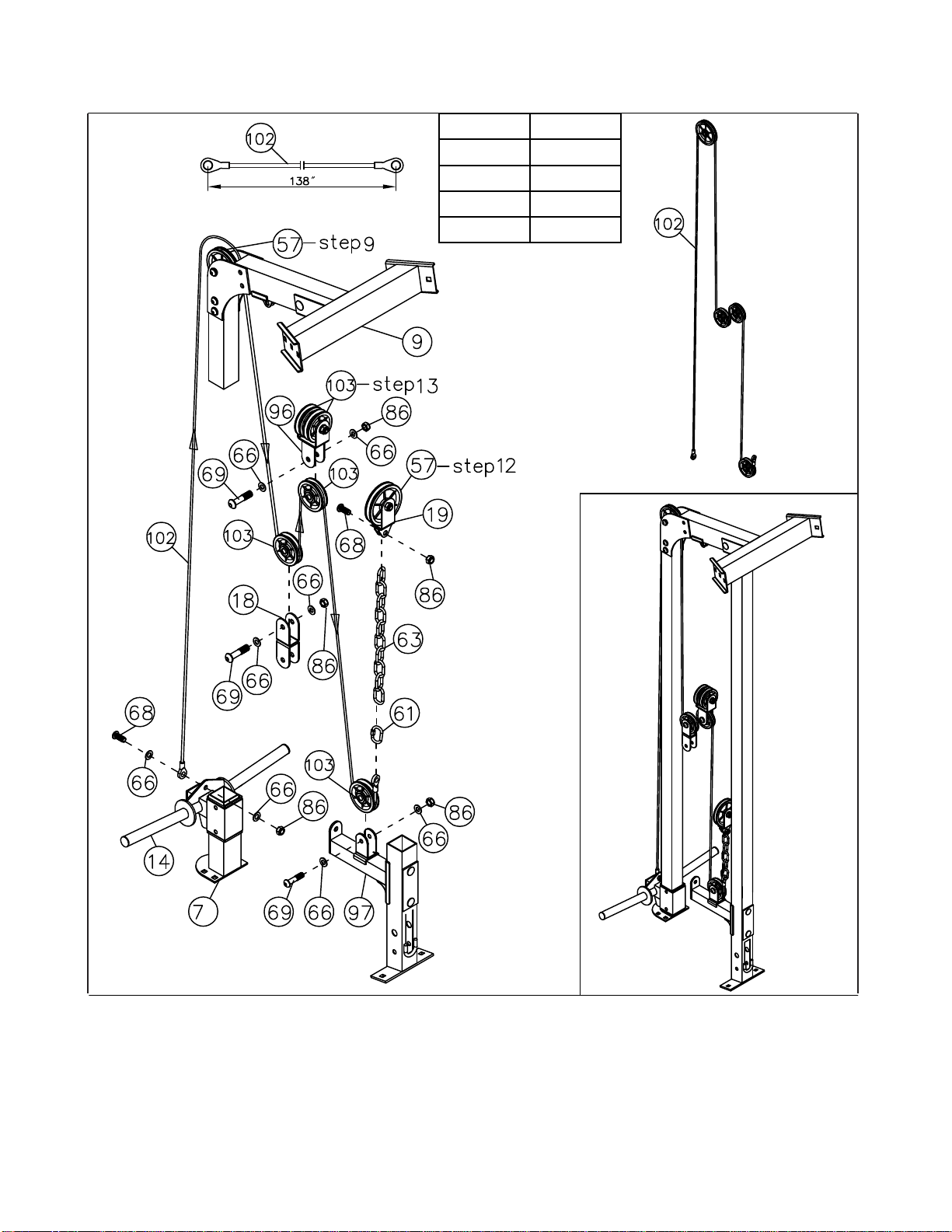
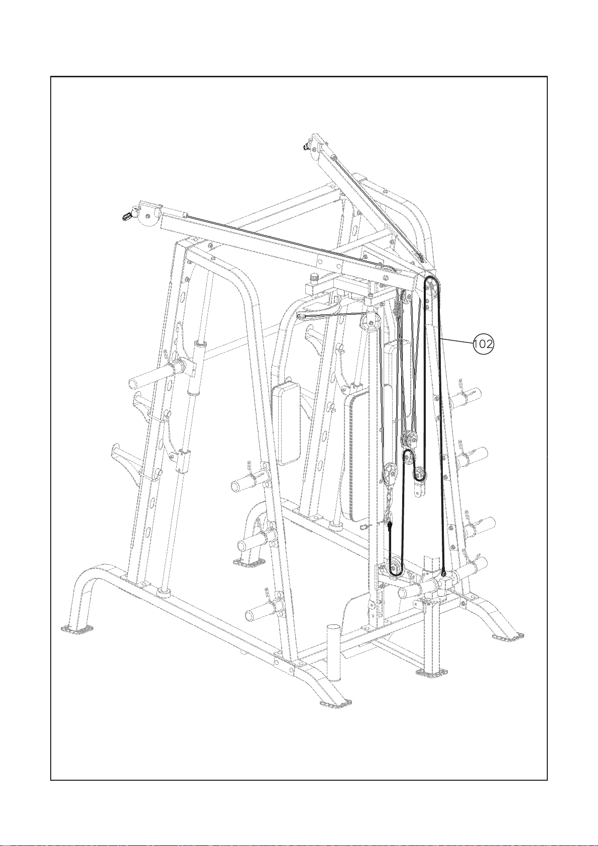
Sliding Wei
ght Post Cable assembly instruction Step-
A.) Attach one end of the 138” Sliding Weight Post Cable (#102) to the triangular bracket on the
Sliding Weight post (#14). Secure it with one M10 x 1” Allen Bolt (#69), two Ø ¾” Washers (#66),
and one M10 Aircraft Nut (#86).
B.) Draw the Cable upward to the Pulley on top of the Rear Upper Frame (#9).
C.) Draw the Cable around the Pulley then downward. Attach a Small Pulley (#103) to a Double
Floating Pulley Bracket (#18). Secure it with one M10 x 1 ¾” Allen Bolt (#69), two Ø ¾” Washers
(#66), and one M10 Aircraft Nut (#86).
D.) Draw the Cable around the Pulley then upward to the Triple Floating Pulley Bracket (#96).
E.) Attach a Small Pulley (#103) to open Bracket. Secure it with one M10 x 1 ¾” Allen Bolt (#69), two
Ø ¾” Washers (#66), and one M10 Aircraft Nut (#86). Draw the Cable around the Pulley then
downward to the open bracket one the Pulley Support Frame (#97).
F.) Attach a Small Pulley to the open bracket. Secure it with one M10 x 1 ¾” Allen Bolt (#69), two Ø
¾” Washers (#66), and one M10 Aircraft Nut (#86). Draw the Cable around the Pulley and upward.
G.) Connect the Cable to a Short Chain (#63) with a C-clip (#61). Connect the Short Chain to the
Single Floating Pulley Bracket (#19). Secure the Chain to the bracket with one M10 x 1” Allen Bolt
(#68) and one M10 Aircraft Nut (#86).
H.) After completing the entire cable installations, come back to this Short Chain to adjust the tension
of the Cable System by adjusting the length of the Chain with the C-clip.
4
©IMPEX INC.
16
www.marcypro.com
14
#18 BOX 2
#61 BOX 2
#63 BOX 2
#102 BOX 2
#103 BOX 2
©IMPEX INC.
17
www.marcypro.com
14-A
©IMPEX INC.
18
www.marcypro.com

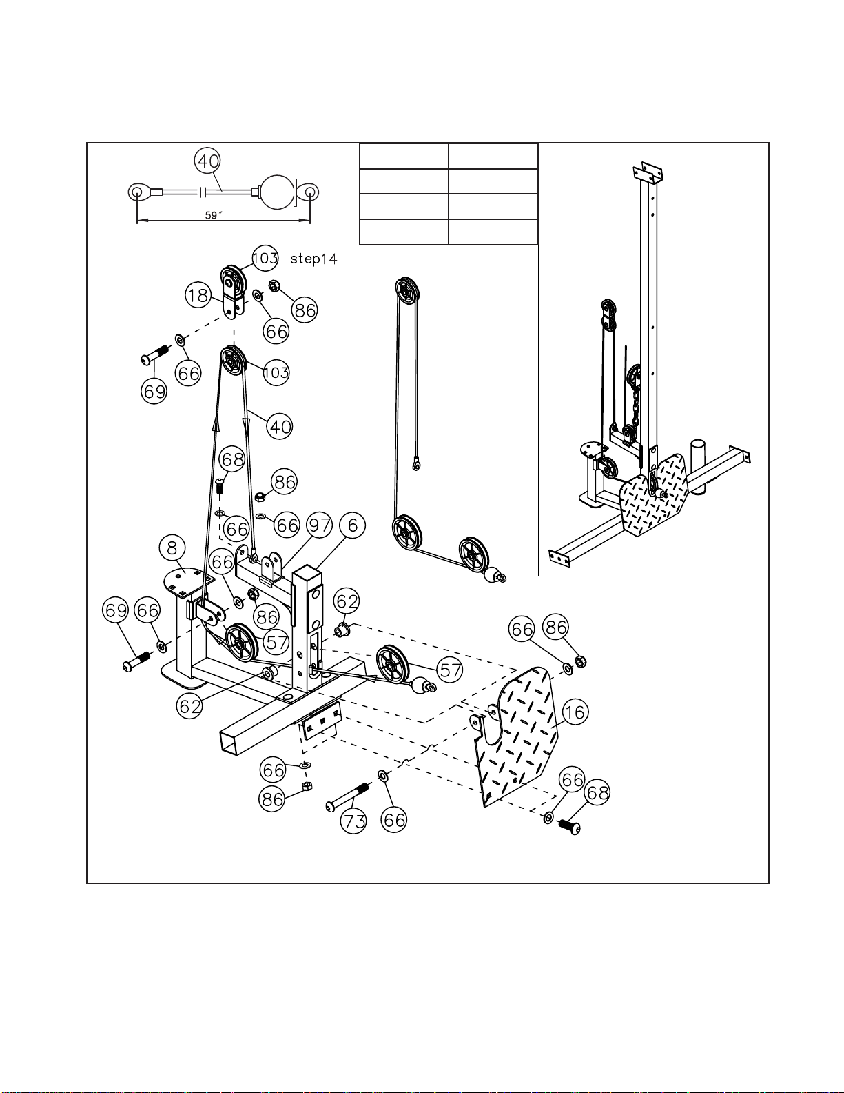
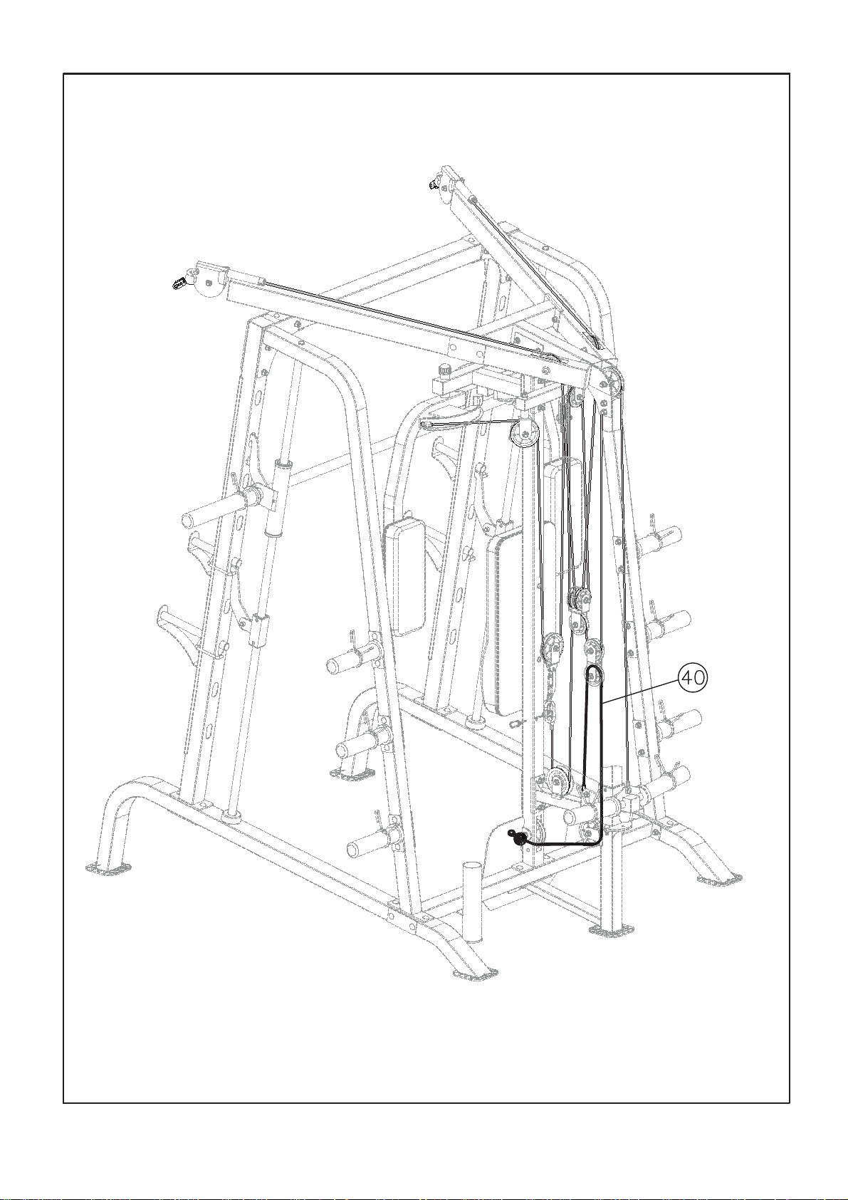
,Step-15A
15Lower C
able assembly instruction Step-
A.) Attach the 59” Lower Cable (#40) to a Pulley (#57) to the bottom opening on the Rear Vertical
Beam (#6). Secure the Pulley to the Rear Vertical Beam with the Foot Plate (#16), one M10 x 3
⅜ ” Allen Bolt (#73), two Ø ¾” Washers (#66), and one M10 Aircraft Nut (#86). Secure the Foot
Plate to the Cross Brace (#2) with two M10 x 1” Allen Bolts (#68), four Ø ¾” Washers (#66), and
two M10 Aircraft Nuts (#86).
B.) Draw the Cable underneath the Pulley to the open bracket on the Weight Glide Base (#8).
Attach a Pulley to the bracket. Secure it with one M10 x 1 ¾” Allen Bolt (#69), two Ø ¾” Washers
(#66), and one M10 Aircraft Nut (#86).
C.) Draw the Cable around the Pulley then upward to the Double Floating Pulley Bracket (#18).
Attach a Small Pulley (#103) to the Bracket. Secure it with one M10 x 1 ¾” Allen Bolt (#69), two Ø
¾” Washers (#66), and one M10 Aircraft Nut (#86).
D.) Draw the Cable around the Pulley then downward to the open bracket on the Pulley Support
Frame (#97). Secure the end of the Cable with one M10 x 1” Allen Bolt (#68), two Ø ¾” Washers
(#66), and one M10 Aircraft Nut (#86).
E.) Connect the Shiver Bar (#30) to a Long Chain (#64) with a C-clip (#61). Connect the Long Chain
to the Cable with another C-clip.
©IMPEX INC.
19
www.marcypro.com
15
#16 BOX 2
2 XOB04#
#57 BOX 2
#103 BOX 2
©IMPEX INC.
20
www.marcypro.com
15-A
©IMPEX INC.
21
www.marcypro.com

WEIGHT CAPACITY AND DIMENSION
1. Maximum user weight: 300 lbs.
2. Maximum weight on Sliding Weight Post (#14): 300 lbs (150lbs on each side)
3. Maximum weight on storage Weight Post (#17): 100 lbs
4. Maximum weight on Bar Holder (#21 & #22) and Safety Holder (#23 & #24): 300 lbs
5. Maximum weight on Weight Bar (#28): 300 lbs
6. Maximum weight on Bench: 600lbs (including user weights)
7. Cage assembled dimensions: 68.7” x 83” x 86”
8. Bench assembled dimensions: 78” x 28.5” x 47”
CARE AND MAINTENANCE
1. Lubricate moving parts with WD-40 or light oil periodically.
2. Inspect and tighten all parts before using the equipment.
3. The equipment can be cleaned using a damp cloth and mild non-abrasive detergent.
DO NOT use solvents.
4. Examine the equipment regularly for signs of damage or wear.
5. Replace any defective components immediately and/or keep the equipment out of use until
repair.
6. Failure to examine regularly may affect the safety level of the equipment.
©IMPEX INC.
22
www.marcypro.com
OPERATION NOTES
This equipment should be placed on flat surface. The incline or decline of surface should
be limited to 3% or less for best performance and safety.
Cable Tension Adjustment
Adjust the tension of the Cable System by adjusting the length of Short Chain
(#63) which is connected by C-clip (#61) to Sliding Weight Post Cable (#102).
If the tension is too loose, move C-clip (#61) up to shorten the length of Chain.
If the tension is too tight, move C-clip (#61) down to extend the length of
Chain.
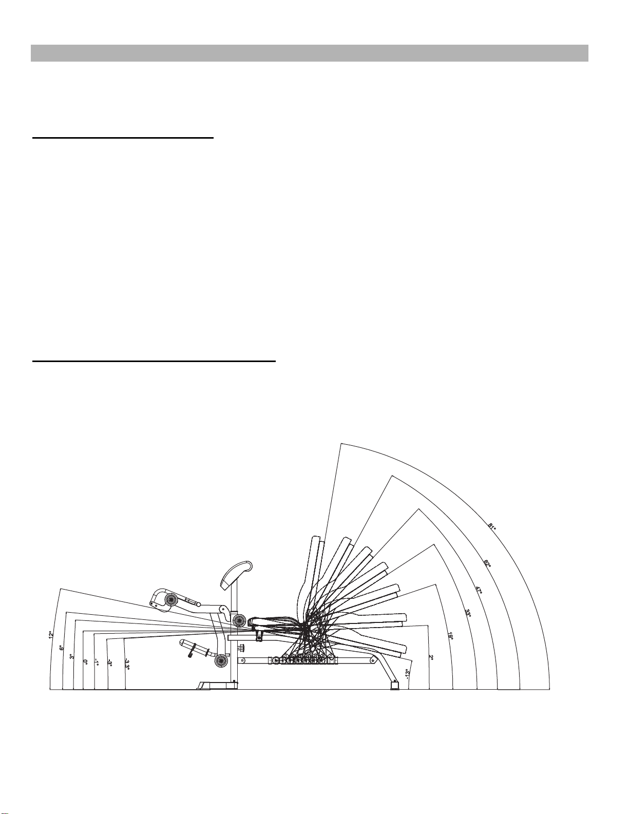
Bench Backrest Adjustment Angles
Backrest adjustment angle ranges from -13
0
to 81
0
.
©IMPEX INC.
23
www.marcypro.com

MD-9010G WEIGHT RESISTANCE CHART
Station
Ratio
Example
Low Pulley 200% 10 lb. plate creates 20 lb. resistance
Lat Pull 50% 10 lb. plate creates 5 lb. resistance
Butterfly (both arms) 100% 10 lb. plate creates 10 lb. resistance
Left Cross-Over 50% 10 lb. plate creates 5 lb resistance
Right Cross-Over
50%
10 lb. plate creates 5 lb resistance
*Numbers are approximate. Actual resistance may vary.
©IMPEX INC.
24
www.marcypro.com

MD-9010G SMITH MACHINE PARTS LIST
PART NO
DESCRIPTION
SIZE
QUANTITY
1
Base Frame
2
2
Cross Brace
1
3
Front Vertical Beam
2
4
Left Vertical Frame
1
5
Right Vertical Frame
1
6
Rear Vertical Frame
1
7
Weight Guide Post
1
8
Weight Guide Base
1
9
Rear Upper Frame
1
10
Left Butterfly
1
11
Right Butterfly
1
12
Butterfly Base
1
13
Butterfly Pulley Bracket
1
14
Sliding Weight Post
1
15
Front Top Beam
1
16
Foot Plate
1
17
Weight Post
6
18
Double Floating Pulley Bracket
1
19
Single Floating Pulley Bracket
1
20
Swivel Pulley Bracket
2
21
Left Bar Holder
1
22
Right Bar Holder
1
23
Left Safety Catch
1
24
Right Safety Catch
1
25
Guide Rod
2
26
Safety Stop Frame
2
27
Lifting Sleeve
1
28
Weight Bar
1
29
Lat Bar
1
30
Shiver Bar
1
31
Curl Handle
1
32
Chrome Panel
2
33
Triangle Bracket
7 ⅛” x 7 ⅛”
2
34
Bracket
5 ⅛” x 2 ¾”
2
35
Bracket
5 ⅛” x 2 ⅜”
2
36
Bracket
4 ¾” x 2”
9
37
Bracket
6 ¼” x 2”
2
38
Backrest Board
1
39
Butterfly Arm Pad
2
40
Lower Cable
59”
1
41
Upper Cable
229”
1
©IMPEX INC.
25
www.marcypro.com

42
Butterfly Cable
87”
1
43
Olympic Sleeve
8
44
Long Olympic Sleeve
2
45
Curl Bar Handle Grip
2
46
Lat Bar Grip
2
47
Bushing
Ø 1” x 3 ⅛”
2
48
Bushing
Ø 1 ½” x 1”
2
49
End Cap
1 ½” x 1 ½”
2
50
End Cap
1 ¾” x 1 ¾”
7
51
End Cap
2 ⅜” x 2 ⅜”
2
52
End Cap
2 ¾” x 2”
2
53
Cone-shaped End Cap
Ø 1”
12
54
Sleeve
2 ⅜” x 2”
2
55
Sliding Sleeve
4
56
Lock Ring
2
57
Pulley
10
58
Rubber Bumper
Ø 1 ¾”
1
59
Rubber Bumper
Ø 2 ½”
2
60
Spring Clip
Ø 1 ⅞”
10
61
C-clip
5
62
Pulley Bushing
Ø ⅞” x ⅝”
6
63
Short Chain
10-link
2
64
Long Chain
15-link
1
65
Washer
Ø ⅝”
6
66
Washer
Ø ¾”
100
67
Washer
Ø 1 ½”
2
68
Allen Bolt
M10 x 1”
12
69
Allen Bolt
M10 x 1 ¾”
11
70
Allen Bolt
M10 x 2 ½”
2
71
Allen Bolt
M10 x 3”
2
72
Allen Bolt
M10 x 3 ⅛”
2
73
Allen Bolt
M10 x 3 ⅜”
2
74
Carriage Bolt
M10 x 1”
4
75
Carriage Bolt
M10 x 2 ¾”
22
76
Carriage Bolt
M10 x 3”
10
77
Carriage Bolt
M10 x 3 ⅛”
4
78
Carriage Bolt
M10 x 3 ⅜”
8
79
Carriage Bolt
M10 x 3 ½”
4
80
Allen Bolt
M8 x 2 ½”
6
81
Allen Bolt
M8 x ⅜”
2
82
Phillips Screw
M6 x ⅝”
1
83
Allen Bolt
M6 x 1 ¼”
2
84
Chrome Panel Screw
8
©IMPEX INC.
26
www.marcypro.com

85
Aircraft Nut
M6
2
86
Aircraft Nut
M10
82
87
End Cap
Ø 1”
6
88
V Bar
1
89
Ankle Strap
1
90
Single Handle Strap
2
91
Triceps Rope
1
92
Lower Safety Stop Frame
2
93
Safety Hook
2
94
Left Upper Frame
1
95
Right Upper Frame
1
96
Triple Floating Pulley Bracket
1
97
Pulley Support Frame
1
98
Single Small Pulley Bracket
1
99
Cross-Over Swivel Pulley Bracket
2
100
Bushing
Ø ⅞” x Ø ⅝”
2
101
Bracket
4 ¾” x 2 ¾”
2
102
Sliding Weight Post Cable
138”
1
103
Small Pulley
7
104
Allen Bolt
M10 x 1 ⅛”
2
105
Allen Bolt
M10 x 2 ¾”
1
106
Allen Screw
M6 x ¼”
4
107
Linear Bearing
4
108
Linear Bearing Cover
4
109
Phillips Screw
M6 x ¼”
4
Allen Wrench (Tool)
6#
1
Allen Wrench (Tool)
5#
1
Allen Wrench (Tool)
4#
1
Allen Wrench (Tool)
3#
1
©IMPEX INC.
27
www.marcypro.com
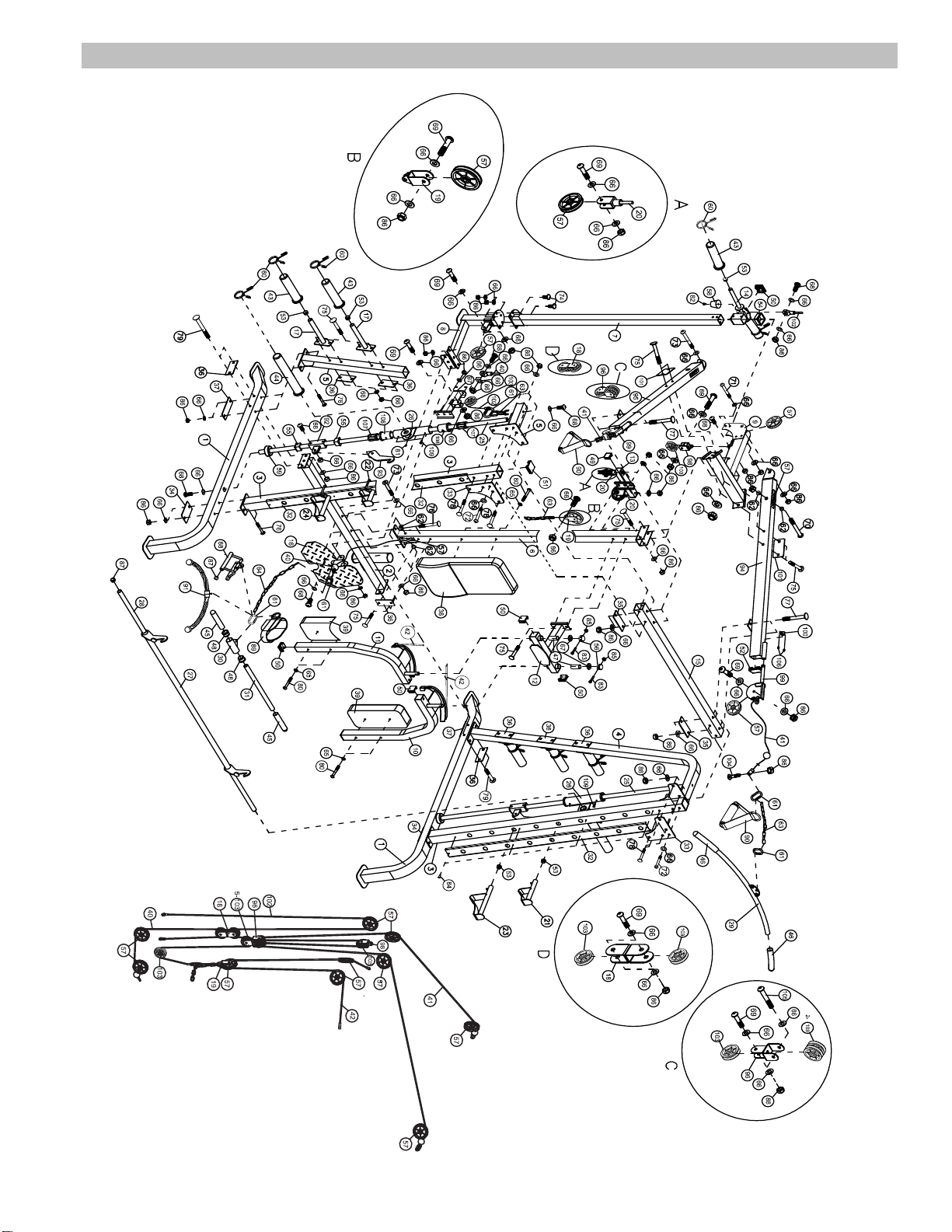
MD-9010G S
MITH MACHINE EXPLODED DIAGRAM
©IMPEX INC.
28
www.marcypro.com

MD-9010G BENCH
PARTS LIST
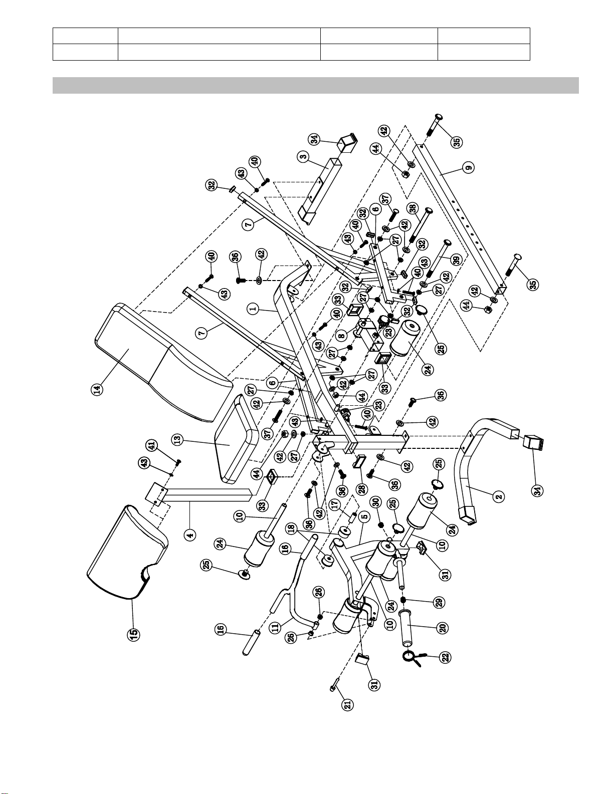
PART NO DESCRI
PTION SIZE QUANTITY
1 Main Fram
e 1
2 Front Stab
ilizer 1
3 Rear St
abilizer 1
4 Arm Cur
l Stand 1
5 Leg Developer 1
6 Seat Support Frame 2
7 Backres
t Support 2
8 Sliding B
lock 1
9 Incline A
djustment Bar 1
10 Foam Tube 3
11 Arm Curl Ha
ndle 1
12 Manual 1
13 Seat Pad 1
14 Backrest B
oard 1
15 Arm Curl Pa
d 1
16 Curl Bar H
andle Grip 2
17 Axle 1
18 Bushing Ø 2 ⅜” 2
19 T
ool
(
A
l
l
en Wrenches) 4
20 Olympic S
leeve 1
21 Lock Pin 3” 1
22 Spring Clip Ø
1 ⅞” 1
23 Lock Knob M18 2
24 Foam
R
ol
l 6
25 Foam Roll End C
ap 6
26 Bushi
ng Ø 1” x ¾” 2
27 Bushing Ø ¾” x
¼” 16
28 End Cap 3 ⅛” x 1
⅝” 1
29 Cone-shaped End Cap Ø 1” 1
30 End Cap Ø 1” 1
31 End Cap 1 ⅝” x 2
⅜” 2
32 End Cap 1 ⅝” x
¾” 12
33 Sliding Block Sleeve 2” 3
34 Stabiliz
er End Cap 4
35 Carriage B
olt M10 x 2 ½” 2
36 Allen Bolt M
10 x ¾” 6
37 Allen Bolt M
10 x 1 ¾” 2
38 Allen Bolt M
10 x 6 ¾” 1
39 Allen Bolt M
10 x 8 ¼” 1
40 Allen Bolt M
8 x 2” 8
41 Allen Bolt M8
x ⅝” 2
42 Washer Ø ¾” 14
©IMPEX INC.
29
www.marcypro.com
43 Washer Ø ⅝” 10
44 A
ir
c
r
a
f
t Nut M10 4
MD-9010G BENCH EXPL
ODED DIAGRAM
©IMPEX INC.
30
www.marcypro.com

IMPEX
®
INC.
LIMITE
D WARRANTY
IMPEX Inc
. ("IMPEX
®
") warrant
s this product to be free from defects in workmanship and material, under normal use
and service conditions, for a period of two years on the Frame from the date of purchase. This warranty extends only
to the original purchaser. IMPEX's obligation under this Warranty is limited to replacing or repairing, at IMPEX's option.
All returns must be pre-authorized by IMPEX. Pre-authorization may be obtained by calling IMPEX Customer Service
Department at 1-800-999-8899. All freights on products returned to IMPEX must be prepaid by the customer. This
warranty does not extend to any product or damage to a product caused by or attributable to freight damage, abuse,
misuse, improper or abnormal usage or repairs not provided by an IMPEX authorized service centre or for products
used for commercial or rental purposes. No other warranty beyond that specifically set forth above is authorized by
IMPEX.
IMPEX is not responsible or liable for indirect, special or consequential damages arising out of or in connection with
the use or performance of the product or other damages with respect to any economic loss, loss of property, loss of
revenues or profits, loss of enjoyments or use, costs of removal, installation or other consequential damages of
whatsoever natures. Some States do not allow the exclusion or limitation of incidental or consequential damages.
Accordingly, the above limitation may not apply to you.
The warranty extended hereunder is in lieu of any and all other warranties and any implied warranties of
merchantability or fitness for a particular purpose is limited in its scope and duration to the terms set forth herein.
Some States do not allow limitations on how long an implied warranty lasts. Accordingly, the above limitation may not
apply to you.
This warranty gives you specific legal right. You may also have other rights which vary from State to State.
Register
online at www.marcypro.com.
IMPEX
®
INC.
2801 S. Tow
ne Ave.
Pomona, CA 91766
ORDERING REP
LACEMENT PARTS
Replacement par
ts can be ordered by calling our Customer Service Department toll-free at 1-800-999-8899 during our
regular business hours: Monday through Friday, 9 a.m. to 5 p.m. Pacific standard time.
support@impex-fitness.com
When ordering repl
acement parts, always give the following information.
1. Model
2. Description of Parts
3. Part Number
4. Date of Purchase
©IMPEX INC.
31
www.marcypro.com