
P/NO : MFL68460504
INSTALLATION MANUAL
AIR
CONDITIONER
Please read this installation manual completely before installing the product.
Installation work must be performed in accordance with the national wiring
standards by authorized personnel only.
Please retain this installation manual for future reference after reading it
thoroughly.
http://www.lghvac.com
www.lg.com
Copyright © 2016 - 2018 LG Electronics Inc. All Rights Reserved.
ENGLISH
FRANÇAIS
ESPAÑOL

• Do not cool excessively indoors. This may be harmful for your health and may consume more
electricity.
• Block sunlight with blinds or curtains while you are operating the air conditioner.
• Keep doors or windows closed tightly while you are operating the air conditioner.
• Adjust the direction of the air flow vertically or horizontally to circulate indoor air.
• Speed up the fan to cool or warm indoor air quickly, in a short period of time.
• Open windows regularly for ventilation as the indoor air quality may deteriorate if the air condi-
tioner is used for many hours.
• Clean the air filter once every 2 weeks. Dust and impurities collected in the air filter may block the
air flow or weaken the cooling / dehumidifying functions.
For your records
Staple your receipt to this page in case you need it to prove the date of purchase or for warranty
purposes. Write the model number and the serial number here:
Model number :
Serial number :
You can find them on a label on the side of each unit.
Dealer’s name :
Date of purchase :
Here are some tips that will help you minimize the power consumption when you use the air
conditioner. You can use your air conditioner more efficiently by referring to the instructions
below:
TIPS FOR SAVING ENERGY
2
ENGLISH
TIPS FOR SAVING ENERGY

3
IMPORTANT SAFETY INSTRUCTIONS
ENGLISH
IMPORTANT SAFETY INSTRUCTIONS
READ ALL INSTRUCTIONS BEFORE USING THE APPLIANCE.
Always comply with the following precautions to avoid dangerous situations and ensure peak
performance of your product
WARNING
It can result in serious injury or death when the directions are ignored
CAUTION
It can result in minor injury or product damage when the directions are ignored
WARNING
• Installation or repairs made by unqualified persons can result in hazards to you and others.
Installation of all field wiring and components MUST conform with local building codes or, in
the absence of local codes, with the National Electrical Code 70 and the National Building Con-
struction and Safety Code or Canadian Electrical code and National Building Code of Canada.
• The information contained in the manual is intended for use by a qualified service technician
familiar with safety procedures and equipped with the proper tools and test instruments.
• Failure to carefully read and follow all instructions in this manual can result in equipment mal-
function, property damage, personal injury and/or death.
Installation
• Have all electric work done by a licensed electrician according to "Electric Facility Engineering Stan-
dard" and "Interior Wire Regulations" and the instructions given in this manual and always use a spe-
cial circuit.
- If the power source capacity is inadequate or electric work is performed improperly, electric shock
or fire may result.
• Ask the dealer or an authorized technician to install the air conditioner.
- Improper installation by the user may result in water leakage, electric shock, or fire.
• Always ground the product.
- There is risk of fire or electric shock.
• Always intstall a dedicated circuit and breaker.
- Improper wiring or installation may cause fire or electric shock.
• For re-installation of the installed product, always contact a dealer or an Authorized Service Center.
- There is risk of fire, electric shock, explosion, or injury.
• Do not install, remove, or re-install the unit by yourself (customer).
- There is risk of fire, electric shock, explosion, or injury.
• Do not store or use flammable gas or combustibles near the air conditioner.
- There is risk of fire or failure of product.
• Use the correctly rated breaker or fuse.
- There is risk of fire or electric shock.
• Prepare for strong wind or earthquake and install the unit at the specified place.
- Improper installation may cause the unit to topple and result in injury.
• Do not install the product on a defective installation stand.
- It may cause injury, accident, or damage to the product.
!
!
!

• Use a vacuum pump or Inert(nitrogen) gas when doing leakage test or air purge. Do not compress
air or Oxygen and do not use Flammable gases. Otherwise, it may cause fire or explosion.
- There is the risk of death, injury, fire or explosion.
• When installing and moving the air conditioner to another site, do not charge it with a
different refrigerant from the refrigerant specified on the unit.
- If a different refrigerant or air is mixed with the original refrigerant, the refrigerant cycle may mal-
function and the unit may be damaged.
• Do not reconstruct to change the settings of the protection devices.
- If the pressure switch, thermal switch, or other protection device is shorted and operated forcibly,
or parts other than those specified by LGE are used, fire or explosion may result.
• Ventilate before operating air conditioner when gas leaked out.
- It may cause explosion, fire, and burn.
• Securely install the cover of control box and the panel.
- If the cover and panel are not installed securely, dust or water may enter the outdoor unit and fire
or electric shock may result.
• If the air conditioner is installed in a small room, measures must be taken to prevent the refrigerant
concentration from exceeding the safety limit when the refrigerant leaks.
- Consult the dealer regarding the appropriate measures to prevent the safety limit from being ex-
ceeded. Should the refrigerant leak and cause the safety limit to be exceeded, harzards due to lack
of oxygen in the room could result.
Operation
• Do not damage or use an unspecified power cord.
- There is risk of fire, electric shock, explosion, or injury.
• Use a dedicated outlet for this appliance.
- There is risk of fire or electrical shock.
• Be cautious that water could not enter the product.
- There is risk of fire, electric shock, or product damage.
• Do not touch the power switch with wet hands.
- There is risk of fire, electric shock, explosion, or injury.
• When the product is soaked (flooded or submerged), contact an Authorized Service Center.
- There is risk of fire or electric shock.
• Be cautious not to touch the sharp edges when installing.
- It may cause injury.
• Take care to ensure that nobody could step on or fall onto the outdoor unit.
- This could result in personal injury and product damage.
• Do not open the inlet grille of the product during operation. (Do not touch the electrostatic filter, if the unit is so
equipped.)
- There is risk of physical injury, electric shock, or product failure.
IMPORTANT SAFETY INSTRUCTIONS
4
ENGLISH

IMPORTANT SAFETY INSTRUCTIONS
5
ENGLISH
CAUTION
Installation
• Always check for gas (refrigerant) leakage after installation or repair of product.
- Low refrigerant levels may cause failure of product.
• Do not install the product where the noise or hot air from the outdoor unit could damage the neighborhoods.
- It may cause a problem for your neighbors.
• Keep level even when installing the product.
- To avoid vibration or water leakage.
• Do not install the unit where combustible gas may leak.
- If the gas leaks and accumulates around the unit, an explosion may result.
• Use power cables of sufficient current carrying capacity and rating.
- Cables that are too small may leak, generate heat, and cause a fire.
• Do not use the product for special purposes, such as preserving foods, works of art, etc. It is a consumer air
conditioner, not a precision refrigeration system.
- There is risk of damage or loss of property.
• Keep the unit away from children. The heat exchanger is very sharp.
- It can cause the injury, such as cutting the finger. Also the damaged fin may result in degradation of capacity.
• When installting the unit in a hospital, communication station, or similar place, provide sufficient protection
against noise.
-
The inverter equipment, private power generator, high-frequency medical equipment, or radio communication equip-
ment may cause the air conditioner to operate erroneously, or fail to operate. On the other hand, the air conditioner
may affect such equipment by creating noise that disturbs medical treatment or image broadcasting.
• Do not install the product where it is exposed to sea wind (salt spray) directly.
- It may cause corrosion on the product. Corrosion, particularly on the condenser and evaporator fins, could
cause product malfunction or inefficient operation.
Operation
• Do not use the air conditioner in special environments.
-
Oil, steam, sulfuric smoke, etc. can significantly reduce the performance of the air conditioner or damage its parts.
• Do not block the inlet or outlet.
- It may cause failure of appliance or accident.
• Make the connections securely so that the outside force of the cable may not be applied to the terminals.
- Inadequate connection and fastening may generate heat and cause a fire.
• Be sure the installation area does not deteriorate with age.
- If the base collapses, the air conditioner could fall with it, causing property damage, product failure, or per-
sonal injury.
•
Install and insulate the drain hose to ensure that water is drained away properly based on the installation manual.
- A bad connection may cause water leakage.
• Be very careful about product transportation.
- Only one person should not carry the product if it weighs more than 20 kg.
-
Some products use PP bands for packaging. Do not use any PP bands for a means of transportation. It is dangerous.
- Do not touch the heat exchanger fins. Doing so may cut your fingers.
- When transporting the outdoor unit, suspending it at the specified positions on the unit base. Also support the
outdoor unit at four points so that it cannot slip sideways.
!

6
IMPORTANT SAFETY INSTRUCTIONS
ENGLISH
• Safely dispose of the packing materials.
-
Packing materials, such as nails and other metal or wooden parts, may cause stabs or other injuries.
-
Tear apart and throw away plastic packaging bags so that children may not play with them. If children play with a
plastic bag which was not torn apart, they face the risk of suffocation.
• Turn on the power at least 6 hours before starting operation.
- Starting operation immediately after turning on the main power switch can result in severe damage to internal
parts. Keep the power switch turned on during the operational season.
• Do not touch any of the refrigerant piping during and after operation.
- It can cause a burn or frostbite.
• Do not operate the air conditioner with the panels or guards removed.
- Rotating, hot, or high-voltage parts can cause injuries.
• Do not directly turn off the main power switch after stopping operation.
- Wait at least 5 minutes before turning off the main power switch. Otherwise it may result in water leakage or
other problems.
•
Auto-addressing should be done in condition of connecting the power of all indoor and outdoour units. Auto-addressing
should also be done in case of changing the indoor unit PCB.
• Use a firm stool or ladder when cleaning or maintaining the air conditioner.
- Be careful and avoid personal injury.
• Do not insert hands or other objects through the air inlet or outlet while the air conditioner is plugged in.
- There are sharp and moving parts that could cause personal injury.
7
2 TIPS FOR SAVING ENERGY
3 IMPORTANT SAFETY INSTRUC-
TIONS
8 INSTALLATION PROCESS
9 OUTDOOR UNITS INFORMATION
19 ALTERNATIVE REFRIGERANT
R410A
20 SELECT THE BEST LOCATION
22 INSTALLATION SPACE
22 Individual Installation
24 LIFTING METHOD
25 INSTALLATION
25 The location of the Anchor bolts
26 Foundation for Installation
27 Preparation of Piping
30 Plumbing materials and storage methods
32 REFRIGERANT PIPING INSTAL-
LATION
32 Precautions on Pipe connection / Valve operation
33 Installation procedure for HR unit
33 Connection of Outdoor units
34 Installation of Outdoor Unit, HR Unit and Indoor Unit
Refrigerant Pipe
35 Type of HR Unit
35 Type of HR Unit
36 Installation of Zoning Control
38 PIPE CONNECTIONS BETWEEN
INDOOR AND OUTDOOR UNIT
38 Preparation Work
39 Pipe Drawing Out during Single / Series connection
41 Refrigerant piping system
52 Refrigerant charging
53 Branch pipe Fitting
57 Leak Test and Vacuum drying
59 Vacuum Mode
60 Thermal insulation of refrigerant piping
61 ELECTRICAL WIRING
61 Caution
63 Control box and connecting position of wiring
64 Communication and Power Cables
65 Wiring of main power supply and equipment capacity
66 Field Wiring
79 Checking the setting of outdoor units
80 Switch for setup of HR Unit
80 HR UNIT PCB
85 Automatic Addressing
89 Example of manual valve addressing (Non-Zoning
setting)
90 Example of manual valve addressing (Zoning setting)
91 Method of checking the pipe detection result at out-
door unit
91 Identification of Manual Valve ID (Address)
91
Method of checking the pipe detection result at HR unit
92 Setting method of Master indoor unit in zoning
94 Group Number setting
95 TEST RUN
95 Cool & Heat selector
96 Static pressure compensation mode
97 Night Low Noise Function
98 Overall defrost mode
99 Setting the ODU address
100 Snow removal & rapid defrost
101 Target pressure adjusting
102 Self-Diagnosis Function
106 CAUTION FOR REFRIGERANT
LEAK
106 Introduction
106 Checking procedure of limiting concentration
108 INSTALLATION GUIDE AT THE
SEASIDE
109 OUTDOOR UNIT (ODU) INSTAL-
LATION DETAILS FOR (3) FOAM
SCREW PROTECTOR PADS.
TABLE OF CONTENTS
TABLE OF CONTENTS
ENGLISH
8
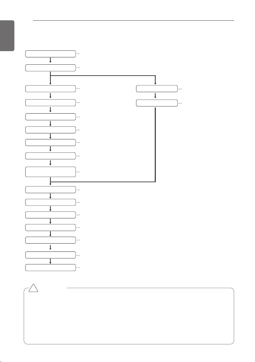
INSTALLATION PROCESS
ENGLISH
The foundation must be level even
Outdoor unit foundation work
Avoid short circuits and ensure
sufficient space is allowed for service
Installation of outdoor unit
Refer to automatic addressing flowchart
Automatic addressing of indoor unit
In the final check for 24hours at 3.8 MPa(38.7 kgf/cm
2
) there must be no drop in pressure.
Airtight test
Multiple core cable must not be used.
(suitable cable should be selected)
Electrical work
(connection circuits and drive circuits)
Make sure no gaps are left where
the insulating materials are joined
Heat insulation work
Make sure airflow is sufficient
Duct work
Adjust to downward gradient
Drain pipe work
Special attention to dryness,
cleanness and tightness
Refrigerant piping work
Check model name to make
sure the fitting is made correctly
Installation of indoor unit
Take account of gradient
of drain piping
Sleeve and insert work
Make connection clearly between outdoor, indoor, remote controller and option.
Preparation of contract drawings
Indicate clearly who will be responsible for switch setting.
Determination of division work
The vacuum pump used must have a capacity of reaching at least 5 torr, more than 1 hour
Vacuum drying
Recharge correctly as calculated in this manual. and record the amount of added refrigerant
Additional charge of refrigerant
Make sure there are no gaps left between the facing materials used on the ceiling
Fit facing panels
Run each indoor unit in turn to make sure the pipe work has been fitted correctly
Test run adjustment
Explain the use of the system as clearly as possible to your customer and make sure all relevant
documentation is in order
Transfer to customer with explanation
Preheat the crank case with the electrical heater for more than 6 hours.
CAUTION
• The above list indicates the order in which the individual work operations are normally car-
ried out but this order may be varied where local conditions warrants such change.
• The thickness of the piping should comply with the relevant local and national regulations
for the designed pressure 3.8Mpa(551.1psi).
• Since R410A is a mixed refrigerant, the required additional refrigerant must be charged in
its liquid state.(If the refrigerant is charged in its gaseous state, its composition changes
and the system will not work properly.)
!
INSTALLATION PROCESS
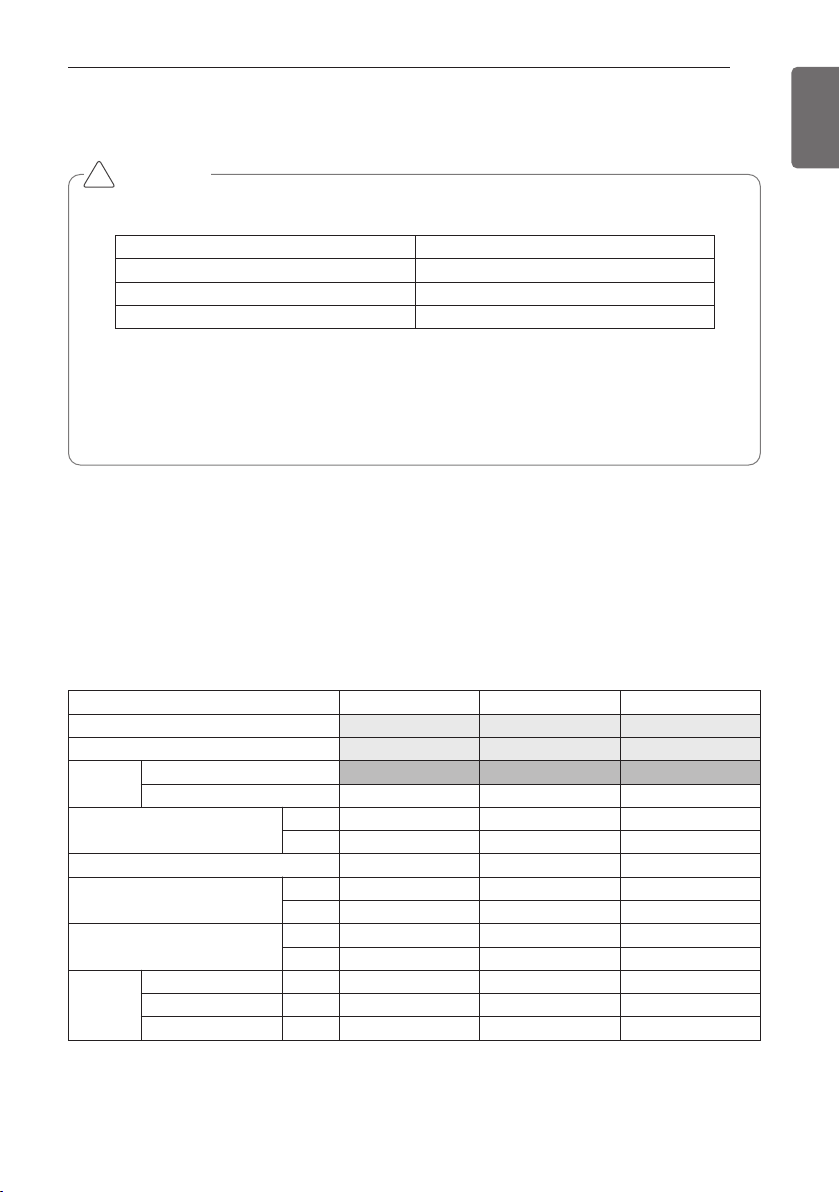
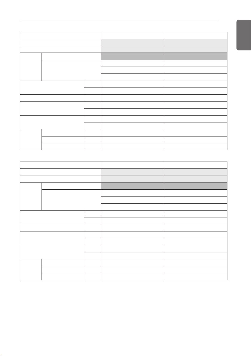
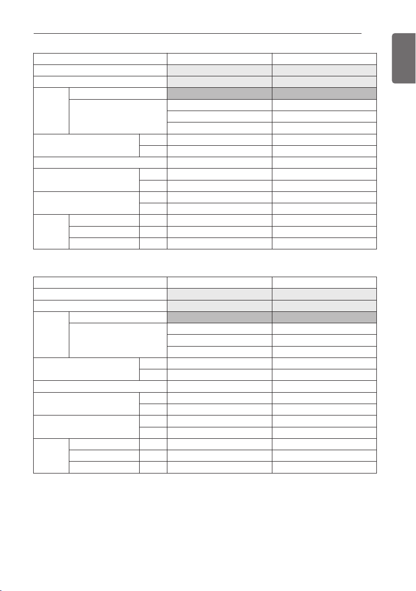
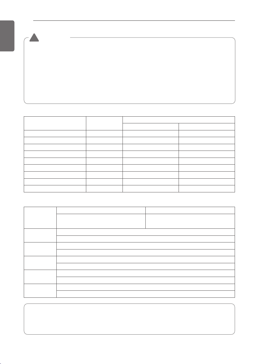
Unit UX2 UX3 UX3
HP 8 10 12
Ton 6 8 10
Model
Name
Combination Unit ARUB072BTE4 ARUB096BTE4 ARUB121BTE4
Independent Unit
Refrigerant Precharged Amount
kg 7.7 10.7 10.7
lbs 16.9 23.6 23.6
Number of maxmum connectable indoor units
13 16 20
Net Weight
kg (195 × 1) (245 × 1) (245 × 1)
lbs (430 × 1) (540 × 1) (540 × 1)
Dimensions (WxHxD)
mm (920×1,680×760)×1 (1,240×1,680×760)×1 (1,240×1,680×760)×1
inch (36.2×66.1×29.9)×1 (48.8×66.1×29.9)×1 (48.8×66.1×29.9)×1
Pipe Con-
nections
Liquid Pipes
mm(inch)
9.52(3/8) 9.52(3/8) 12.7(1/2)
Low Pressure Gas Pipes mm(inch)
19.05(3/4) 22.2(7/8) 28.58(1 1/8)
High Pressure Gas Pipes mm(inch)
15.88(5/8) 19.05(3/4) 19.05(3/4)
OUTDOOR UNITS INFORMATION
9
ENGLISH
Power Supply : 3Ø, 208/230V, 60Hz
Model Name : ARUB***BTE4
CAUTION
Notes : * We can guarantee the operation only within 130% Combination.
If you want to connect more than 130% combination, please contact us and dis-
cuss the requirement like below.
• If the operation of indoor unit is more than 130%, the airflow is operated as low in the all
indoor units.
Combination
Outdoor Number Connection Ratio
Single outdoor units 130%
Double outdoor units 130%
Triple outdoor units 130%
!
OUTDOOR UNITS INFORMATION
10
OUTDOOR UNITS INFORMATION
ENGLISH
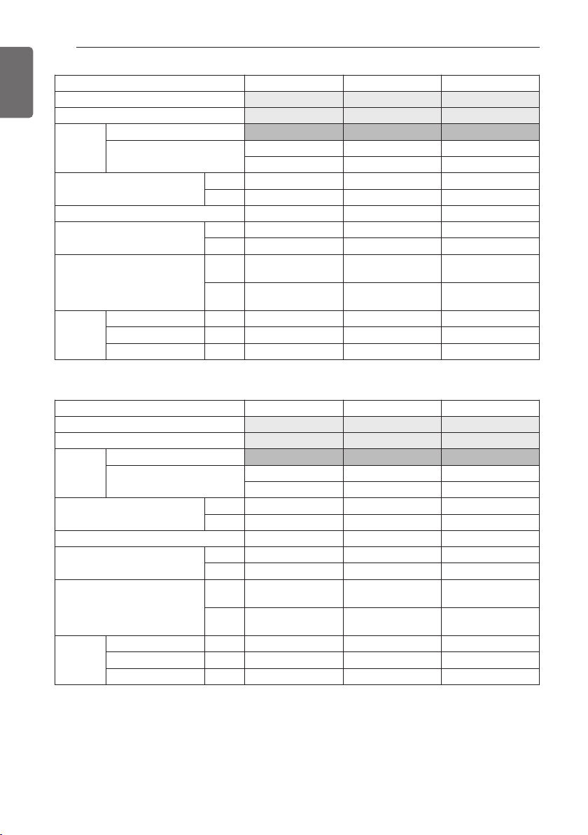
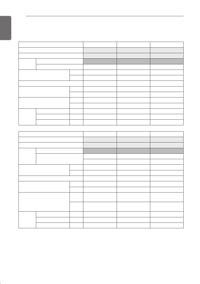
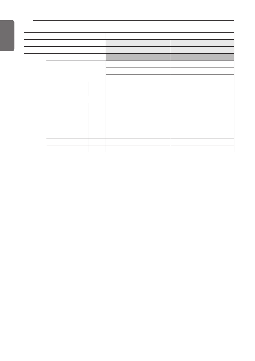
Unit UX2+UX3 UX3+UX3 UX3+UX3
HP 22 24 26
Ton 18 20 22
Model
Name
Combination Unit ARUB216BTE4 ARUB240BTE4 ARUB264BTE4
Independent Unit
ARUB144BTE4 ARUB144BTE4 ARUB144BTE4
ARUB072BTE4 ARUB096BTE4 ARUB121BTE4
Refrigerant Precharged Amount
kg 18.4 21.4 21.4
lbs 40.5 47.2 47.2
Number of maxmum connectable indoor units
35 39 42
Net Weight
kg (195 × 1) + (285 × 1) (245 × 1) + (285 × 1) (245 × 1) + (285 × 1)
lbs (430 × 1) + (628 × 1) (540 × 1) + (628 × 1) (540 × 1) + (628 × 1)
Dimensions (WxHxD)
mm
(920×1,680×760)×1
(1,240×1,680×760)×1
(1,240×1,680×760)×2 (1,240×1,680×760)×2
inch
(36.2×66.1×29.9)×1
(48.8×66.1×29.9)×1
(48.8×66.1×29.9)×2 (48.8×66.1×29.9)×2
Pipe Con-
nections
Liquid Pipes
mm(inch)
15.88(5/8) 15.88(5/8) 19.05(3/4)
Low Pressure Gas Pipes mm(inch)
28.58(1 1/8) 34.9(1 3/8) 34.9(1 3/8)
High Pressure Gas Pipes mm(inch)
28.58(1 1/8) 28.58(1 1/8) 28.58(1 1/8)
Unit UX3 UX3 UX2+UX3
HP 14 18 20
Ton 12 14 16
Model
Name
Combination Unit ARUB144BTE4 ARUB168BTE4 ARUB192BTE4
Independent Unit
ARUB121BTE4
ARUB072BTE4
Refrigerant Precharged Amount
kg 10.7 10.7 18.4
lbs 23.6 23.6 40.5
Number of maxmum connectable indoor units
23 29 32
Net Weight
kg (285 × 1) (285 × 1) (195 × 1) + (245 × 1)
lbs (628 × 1) (628 × 1) (430 × 1) + (540 × 1)
Dimensions (WxHxD)
mm (1,240×1,680×760)×1 (1,240×1,680×760)×1
(920×1,680×760)×1
(1,240×1,680×760)×1
inch (48.8×66.1×29.9)×1 (48.8×66.1×29.9)×1
(36.2×66.1×29.9)×1
(48.8×66.1×29.9)×1
Pipe Con-
nections
Liquid Pipes
mm(inch)
12.7(1/2) 15.88(5/8) 15.88(5/8)
Low Pressure Gas Pipes mm(inch)
28.58(1 1/8) 28.58(1 1/8) 28.58(1 1/8)
High Pressure Gas Pipes mm(inch)
22.2(7/8) 22.2(7/8) 22.2(7/8)
OUTDOOR UNITS INFORMATION
11
ENGLISH
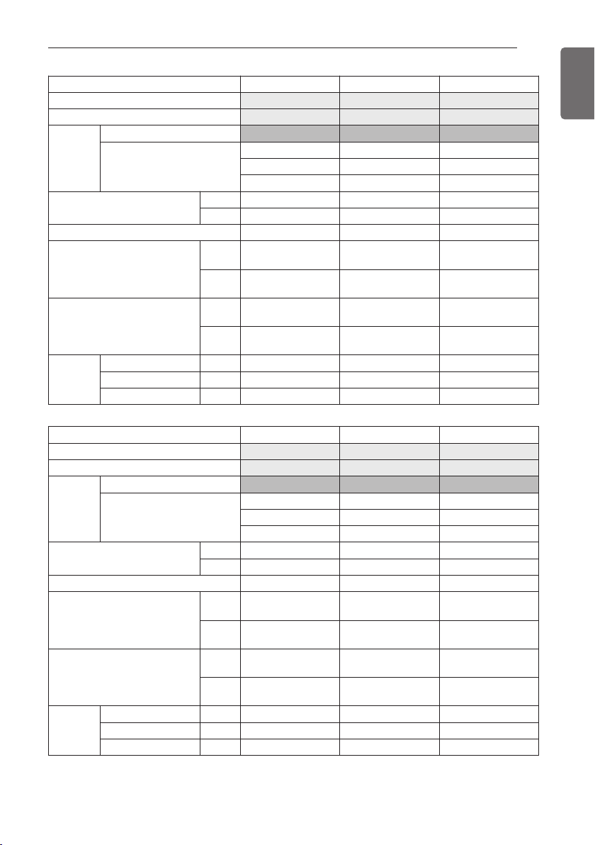
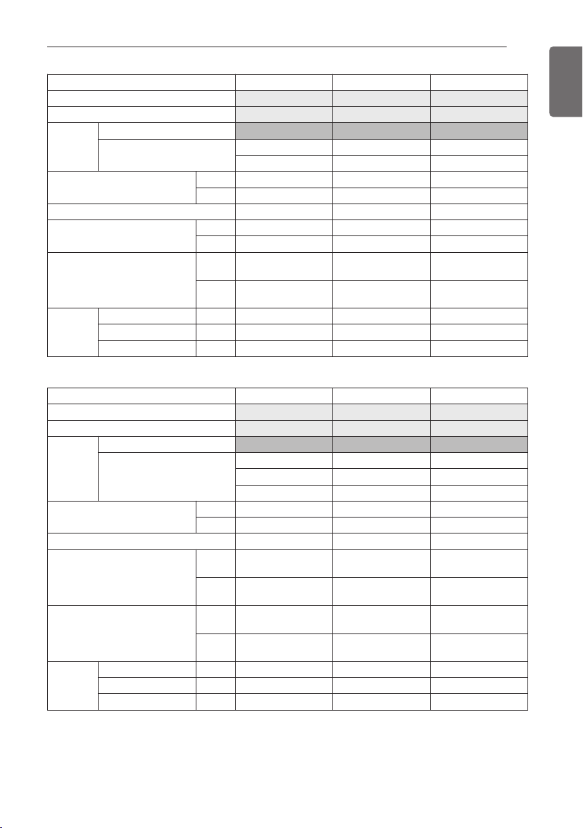
Unit UX3+UX3 UX2+UX3+UX3 UX3+UX3
HP 28 32 32
Ton 24 26 26
Model
Name
Combination Unit ARUB288BTE4 ARUB312BTE4 ARUB313BTE4
Independent Unit
ARUB144BTE4 ARUB144BTE4 ARUB168BTE4
ARUB144BTE4 ARUB096BTE4 ARUB144BTE4
ARUB072BTE4
Refrigerant Precharged Amount
kg 21.4 29.1 21.4
lbs 47.2 64.1 47.2
Number of maxmum connectable indoor units
45 52 52
Net Weight
kg (285 × 2)
(195 × 1) + (245 × 1)
+ (285 × 1)
(285 × 2)
lbs (628 × 2)
(430 × 1) + (540 × 1)
+ (628 × 1)
(628 × 2)
Dimensions (WxHxD)
mm (1,240×1,680×760)×2
(920×1,680×760)×1
(1,240×1,680×760)×2
(1,240×1,680×760)×2
inch (48.8×66.1×29.9)×2
(36.2×66.1×29.9)×1
(48.8×66.1×29.9)×2
(48.8×66.1×29.9)×2
Pipe Con-
nections
Liquid Pipes
mm(inch)
19.05(3/4) 19.05(3/4) 19.05(3/4)
Low Pressure Gas Pipes mm(inch)
34.9(1 3/8) 34.9(1 3/8) 34.9(1 3/8)
High Pressure Gas Pipes mm(inch)
28.58(1 1/8) 28.58(1 1/8) 28.58(1 1/8)
Unit UX3+UX3+UX3 UX3+UX3 UX3+UX3+UX3
HP 34 34 36
Ton 28 28 30
Model
Name
Combination Unit ARUB336BTE4 ARUB337BTE4 ARUB360BTE4
Independent Unit
ARUB144BTE4 ARUB168BTE4 ARUB144BTE4
ARUB096BTE4 ARUB168BTE4 ARUB121BTE4
ARUB096BTE4 ARUB096BTE4
Refrigerant Precharged Amount
kg 32.1 21.4 32.1
lbs 70.8 47.2 70.8
Number of maxmum connectable indoor units
55 55 58
Net Weight
kg (245 × 2) + (285 × 1) (285 × 2) (245 × 2) + (285 × 1)
lbs (540 × 2) + (628 × 1) (628 × 2) (540 × 2) + (628 × 1)
Dimensions (WxHxD)
mm (1,240×1,680×760)×3 (1,240×1,680×760)×2 (1,240×1,680×760)×3
inch (48.8×66.1×29.9)×3 (48.8×66.1×29.9)×2 (48.8×66.1×29.9)×3
Pipe Con-
nections
Liquid Pipes
mm(inch)
19.05(3/4) 19.05(3/4) 19.05(3/4)
Low Pressure Gas Pipes mm(inch)
34.9(1 3/8) 34.9(1 3/8) 41.3(1 5/8)
High Pressure Gas Pipes mm(inch)
28.58(1 1/8) 28.58(1 1/8) 28.58(1 1/8)
12
OUTDOOR UNITS INFORMATION
ENGLISH
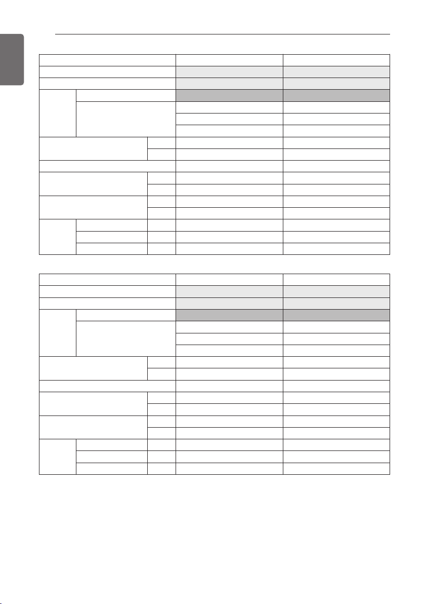
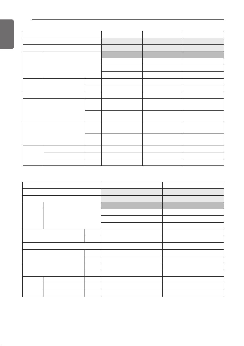
Unit
UX3 UX3+UX3+UX3
HP
14 38
Ton
12 32
Model
Name
Combination Unit
ARUB145BTE4 ARUB384BTE4
Independent Unit
Combination only (Not for 1Unit) ARUB096BTE4
ARUB145BTE4
ARUB145BTE4
Refrigerant Precharged Amount
kg 10.7 32.1
lbs 23.6 70.9
Number of maxmum connectable indoor units
23 61
Net Weight
kg
(305 × 1) 245 + 305 × 2
lbs
(672 × 1) 540 + 672 × 2
Dimensions (WxHxD)
mm
(1,240×1,680×760)×1 (1,240×1,680×760)×3
inch
(48.8×66.1×29.9)×1 (48.8×66.1×29.9)×3
Pipe Con-
nections
Liquid Pipes
mm(inch)
15.88(5/8) 19.05(3/4)
Low Pressure Gas Pipes mm(inch)
28.58(1 1/8) 41.3(1 5/8)
High Pressure Gas Pipes mm(inch)
22.2(7/8) 28.58(1 1/8)
Unit
UX3+UX3+UX3
UX3+UX3+UX3
HP
40
42
Ton
34
36
Model
Name
Combination Unit
ARUB408BTE4
ARUB432BTE4
Independent Unit
ARUB121BTE4
ARUB145BTE4
ARUB145BTE4
ARUB145BTE4
ARUB145BTE4
ARUB145BTE4
Refrigerant Precharged Amount
kg 32.1
32.1
lbs 70.8
70.8
Number of maxmum connectable indoor units
64
64
Net Weight
kg
245 + 305 × 2
305 × 3
lbs
540 + 672 × 2
672 × 3
Dimensions (WxHxD)
mm
(1,240×1,680×760)×3
(1,240×1,680×760)×3
inch
(48.8×66.1×29.9)×3
(48.8×66.1×29.9)×3
Pipe Con-
nections
Liquid Pipes
mm(inch)
19.05(3/4)
19.05(3/4)
Low Pressure Gas Pipes mm(inch)
41.3(1 5/8)
41.3(1 5/8)
High Pressure Gas Pipes mm(inch)
28.58(1 1/8)
28.58(1 1/8)
OUTDOOR UNITS INFORMATION
13
ENGLISH
Unit
UX3 UX3+UX3+UX3
HP
18 46
Ton
14 38
Model
Name
Combination Unit
ARUB169BTE4 ARUB456BTE4
Independent Unit
Combination only (Not for 1Unit) ARUB169BTE4
ARUB145BTE4
ARUB145BTE4
Refrigerant Precharged Amount
kg
10.7 32.1
lbs
23.6 70.8
Number of maxmum connectable indoor units
29 64
Net Weight
kg
(305 x 1) (305 x 3)
lbs
(672 x 1) (672 x 3)
Dimensions (WxHxD)
mm
(1,240x1,680x760)x1 (1,240x1,680x760)x3
inch
(48.8x66.1x29.9)x1 (48.8x66.1x29.9)x3
Pipe Con-
nections
Liquid Pipes
mm(inch)
15.88(5/8) 19.05(3/4)
Low Pressure Gas Pipes mm(inch)
28.58(1 1/8) 41.3(1 5/8)
High Pressure Gas Pipes mm(inch)
22.2(7/8) 28.58(1 1/8)
Unit
UX3+UX3+UX3 UX3+UX3+UX3
HP
48 50
Ton
40 42
Model
Name
Combination Unit
ARUB480BTE4 ARUB504BTE4
Independent Unit
ARUB145BTE4 ARUB169BTE4
ARUB169BTE4 ARUB169BTE4
ARUB169BTE4 ARUB169BTE4
Refrigerant Precharged Amount
kg
32.1 32.1
lbs
70.8 70.8
Number of maxmum connectable indoor units
64 64
Net Weight
kg
(305 x 3) (305 x 3)
lbs
(672 x 3) (672 x 3)
Dimensions (WxHxD)
mm
(1,240x1,680x760)x3 (1,240x1,680x760)x3
inch
(48.8x66.1x29.9)x3 (48.8x66.1x29.9)x3
Pipe Con-
nections
Liquid Pipes
mm(inch)
19.05(3/4) 19.05(3/4)
Low Pressure Gas Pipes mm(inch)
41.3(1 5/8) 41.3(1 5/8)
High Pressure Gas Pipes mm(inch)
28.58(1 1/8) 28.58(1 1/8)
14
OUTDOOR UNITS INFORMATION
ENGLISH
Power Supply : 3Ø, 460V, 60Hz
Model Name : ARUB***DTE4
Unit UX2 UX3 UX3
HP 8 10 12
Ton 6 8 10
Model
Name
Combination Unit ARUB072DTE4 ARUB096DTE4 ARUB121DTE4
Independent Unit
Refrigerant Precharged Amount
kg 7.7 10.7 10.7
lbs 16.9 23.6 23.6
Number of maxmum connectable indoor units
13 16 20
Net Weight
kg (195 × 1) (245 × 1) (245 × 1)
lbs (430 × 1) (540 × 1) (540 × 1)
Dimensions (WxHxD)
mm (920×1,680×760)×1 (1,240×1,680×760)×1 (1,240×1,680×760)×1
inch (36.2×66.1×29.9)×1 (48.8×66.1×29.9)×1 (48.8×66.1×29.9)×1
Pipe Con-
nections
Liquid Pipes
mm(inch)
9.52(3/8) 9.52(3/8) 12.7(1/2)
Low Pressure Gas Pipes mm(inch)
19.05(3/4) 22.2(7/8) 28.58(1 1/8)
High Pressure Gas Pipes mm(inch)
15.88(5/8) 19.05(3/4) 19.05(3/4)
Unit UX3 UX3 UX2+UX3
HP 14 18 20
Ton 12 14 16
Model
Name
Combination Unit ARUB144DTE4 ARUB168DTE4 ARUB192DTE4
Independent Unit
ARUB121DTE4
ARUB072DTE4
Refrigerant Precharged Amount
kg 10.7 10.7 18.4
lbs 23.6 23.6 40.5
Number of maxmum connectable indoor units
23 29 32
Net Weight
kg (285 × 1) (285 × 1) (195 × 1) + (245 × 1)
lbs (628 × 1) (628 × 1) (430 × 1) + (540 × 1)
Dimensions (WxHxD)
mm (1,240×1,680×760)×1 (1,240×1,680×760)×1
(920×1,680×760)×1
(1,240×1,680×760)×1
inch (48.8×66.1×29.9)×1 (48.8×66.1×29.9)×1
(36.2×66.1×29.9)×1
(48.8×66.1×29.9)×1
Pipe Con-
nections
Liquid Pipes
mm(inch)
12.7(1/2) 15.88(5/8) 15.88(5/8)
Low Pressure Gas Pipes mm(inch)
28.58(1 1/8) 28.58(1 1/8) 28.58(1 1/8)
High Pressure Gas Pipes mm(inch)
22.2(7/8) 22.2(7/8) 22.2(7/8)
OUTDOOR UNITS INFORMATION
15
ENGLISH
Unit UX2+UX3 UX3+UX3 UX3+UX3
HP 22 24 26
Ton 18 20 22
Model
Name
Combination Unit ARUB216DTE4 ARUB240DTE4 ARUB264DTE4
Independent Unit
ARUB144DTE4 ARUB144DTE4 ARUB144DTE4
ARUB072DTE4 ARUB096DTE4 ARUB121DTE4
Refrigerant Precharged Amount
kg 18.4 21.4 21.4
lbs 40.5 47.2 47.2
Number of maxmum connectable indoor units
35 39 42
Net Weight
kg (195 × 1) + (285 × 1) (245 × 1) + (285 × 1) (245 × 1) + (285 × 1)
lbs (430 × 1) + (628 × 1) (540 × 1) + (628 × 1) (540 × 1) + (628 × 1)
Dimensions (WxHxD)
mm
(920×1,680×760)×1
(1,240×1,680×760)×1
(1,240×1,680×760)×2 (1,240×1,680×760)×2
inch
(36.2×66.1×29.9)×1
(48.8×66.1×29.9)×1
(48.8×66.1×29.9)×2 (48.8×66.1×29.9)×2
Pipe Con-
nections
Liquid Pipes
mm(inch)
15.88(5/8) 15.88(5/8) 19.05(3/4)
Low Pressure Gas Pipes mm(inch)
28.58(1 1/8) 34.9(1 3/8) 34.9(1 3/8)
High Pressure Gas Pipes mm(inch)
28.58(1 1/8) 28.58(1 1/8) 28.58(1 1/8)
Unit UX3+UX3 UX2+UX3+UX3 UX3+UX3
HP 28 32 32
Ton 24 26 26
Model
Name
Combination Unit ARUB288DTE4 ARUB312DTE4 ARUB313DTE4
Independent Unit
ARUB144DTE4 ARUB144DTE4 ARUB168DTE4
ARUB144DTE4 ARUB096DTE4 ARUB144DTE4
ARUB072DTE4
Refrigerant Precharged Amount
kg 21.4 29.1 21.4
lbs 47.2 64.1 47.2
Number of maxmum connectable indoor units
45 52 52
Net Weight
kg (285 × 2)
(195 × 1) + (245 × 1) +
(285 × 1)
(285 × 2)
lbs (628 × 2)
(430 × 1) + (540 × 1) +
(628 × 1)
(628 × 2)
Dimensions (WxHxD)
mm (1,240×1,680×760)×2
(920×1,680×760)×1
(1,240×1,680×760)×2
(1,240×1,680×760)×2
inch (48.8×66.1×29.9)×2
(36.2×66.1×29.9)×1
(48.8×66.1×29.9)×2
(48.8×66.1×29.9)×2
Pipe Con-
nections
Liquid Pipes
mm(inch)
19.05(3/4) 19.05(3/4) 19.05(3/4)
Low Pressure Gas Pipes mm(inch)
34.9(1 3/8) 34.9(1 3/8) 34.9(1 3/8)
High Pressure Gas Pipes mm(inch)
28.58(1 1/8) 28.58(1 1/8) 28.58(1 1/8)
16
OUTDOOR UNITS INFORMATION
ENGLISH
Unit
UX3 UX2+UX3+UX3
HP
14 38
Ton
12 32
Model
Name
Combination Unit
ARUB145DTE4 ARUB384DTE4
Independent Unit
Combination only (Not for 1Unit)
ARUB096DTE4
ARUB145DTE4
ARUB145DTE4
Refrigerant Precharged Amount
kg 10.7 32.1
lbs 23.6 70.8
Number of maxmum connectable indoor units
23 61
Net Weight
kg
(285 × 1) (245 x 1) + (285 x 2)
lbs
(628 × 1) (540 x 1) + (628 x 2)
Dimensions (WxHxD)
mm
(1,240×1,680×760)×1 (1,240×1,680×760)×3
inch
(48.8×66.1×29.9)×1 (48.8×66.1×29.9)×3
Pipe Con-
nections
Liquid Pipes
mm(inch)
15.88(5/8) 19.05(3/4)
Low Pressure Gas Pipes mm(inch)
28.58(1 1/8) 41.3(1 5/8)
High Pressure Gas Pipes mm(inch)
22.2(7/8) 28.58(1 1/8)
Unit
UX3+UX3+UX3 UX3+UX3 UX3+UX3+UX3
HP
34 34 36
Ton
28 28 30
Model
Name
Combination Unit
ARUB336DTE4 ARUB337DTE4 ARUB360DTE4
Independent Unit
ARUB144DTE4 ARUB168DTE4 ARUB144DTE4
ARUB096DTE4 ARUB168DTE4 ARUB121DTE4
ARUB096DTE4 ARUB096DTE4
Refrigerant Precharged Amount
kg
32.1 21.4 32.1
lbs
70.8 47.2 70.8
Number of maxmum connectable indoor units
55 55 58
Net Weight
kg
(245 × 2) + (285 × 1) (285 × 2) (245 × 2) + (285 × 1)
lbs
(540 × 2) + (628 × 1) (628 × 2) (540 × 2) + (628 × 1)
Dimensions (WxHxD)
mm
(1,240×1,680×760)×3 (1,240×1,680×760)×2 (1,240×1,680×760)×3
inch
(48.8×66.1×29.9)×3 (48.8×66.1×29.9)×2 (48.8×66.1×29.9)×3
Pipe Con-
nections
Liquid Pipes
mm(inch)
19.05(3/4) 19.05(3/4) 19.05(3/4)
Low Pressure Gas Pipes mm(inch)
34.9(1 3/8) 34.9(1 3/8) 41.3(1 5/8)
High Pressure Gas Pipes mm(inch)
28.58(1 1/8) 28.58(1 1/8) 28.58(1 1/8)
OUTDOOR UNITS INFORMATION
17
ENGLISH
Unit
UX2+UX3+UX3 UX2+UX3+UX3
HP
40 42
Ton
34 36
Model
Name
Combination Unit
ARUB408DTE4 ARUB432DTE4
Independent Unit
ARUB121DTE4 ARUB145DTE4
ARUB145DTE4 ARUB145DTE4
ARUB145DTE4 ARUB145DTE4
Refrigerant Precharged Amount
kg 32.1 32.1
lbs 70.8 70.8
Number of maxmum connectable indoor units
64 64
Net Weight
kg
(245 x 1) + (285 x 2) (285 x 3)
lbs
(540 x 1) + (628 x 2) (628 x 3)
Dimensions (WxHxD)
mm
(1,240×1,680×760)×3 (1,240×1,680×760)×3
inch
(48.8×66.1×29.9)×3 (48.8×66.1×29.9)×3
Pipe Con-
nections
Liquid Pipes
mm(inch)
19.05(3/4) 19.05(3/4)
Low Pressure Gas Pipes mm(inch)
41.3(1 5/8) 41.3(1 5/8)
High Pressure Gas Pipes mm(inch)
28.58(1 1/8) 28.58(1 1/8)
Unit
UX3 UX3+UX3+UX3
HP
18 46
Ton
14 38
Model
Name
Combination Unit
ARUB169DTE4 ARUB456DTE4
Independent Unit
Combination only (Not for 1Unit) ARUB169DTE4
ARUB145DTE4
ARUB145DTE4
Refrigerant Precharged Amount
kg
10.7 32.1
lbs
23.6 70.8
Number of maxmum connectable indoor units
29 64
Net Weight
kg
(285 x 1) (285 x 3)
lbs
(628 x 1) (628 x 3)
Dimensions (WxHxD)
mm
(1,240x1,680x760)x1 (1,240x1,680x760)x3
inch
(48.8x66.1x29.9)x1 (48.8x66.1x29.9)x3
Pipe Con-
nections
Liquid Pipes
mm(inch)
15.88(5/8) 19.05(3/4)
Low Pressure Gas Pipes mm(inch)
28.58(1 1/8) 41.3(1 5/8)
High Pressure Gas Pipes mm(inch)
22.2(7/8) 28.58(1 1/8)
18
OUTDOOR UNITS INFORMATION
ENGLISH
Unit
UX3+UX3+UX3 UX3+UX3+UX3
HP
48 50
Ton
40 42
Model
Name
Combination Unit
ARUB480DTE4 ARUB504DTE4
Independent Unit
ARUB169DTE4 ARUB169DTE4
ARUB169DTE4 ARUB169DTE4
ARUB145DTE4 ARUB169DTE4
Refrigerant Precharged Amount
kg
32.1 32.1
lbs
70.8 70.8
Number of maxmum connectable indoor units
64 64
Net Weight
kg
(285 x 3) (285 x 3)
lbs
(628 x 3) (628 x 3)
Dimensions (WxHxD)
mm
(1,240x1,680x760)x3 (1,240x1,680x760)x3
inch
(48.8x66.1x29.9)x3 (48.8x66.1x29.9)x3
Pipe Con-
nections
Liquid Pipes
mm(inch)
19.05(3/4) 19.05(3/4)
Low Pressure Gas Pipes mm(inch)
41.3(1 5/8) 41.3(1 5/8)
High Pressure Gas Pipes mm(inch)
28.58(1 1/8) 28.58(1 1/8)

ALTERNATIVE REFRIGERANT R410A
19
ENGLISH
• The wall thickness of the piping should comply with the relevant local and national regula-
tions for the designed pressure 3.8Mpa(551.1psi).
• Since R410A is a mixed refrigerant, the required additional refrigerant must be charged in
its liquid state.
If the refrigerant is charged in its gaseous state, its composition changes and the system
will not work properly.
• Do not place the refrigerant container under the direct rays of the sun to prevent it from
exploding.
• For high-pressure refrigerant, any unapproved pipe must not be used.
• Do not heat pipes more than necessary to prevent them from softening.
• Be careful not to install wrongly to minimize economic loss because it is expensive in
comparison with R22.
ALTERNATIVE REFRIGERANT R410A
The refrigerant R410A has the property of higher operating pressure in comparison with R22.
Therefore, all materials have the characteristics of higher resisting pressure than R22 ones and
this characteristic should be also considered during the installation.
R410A is an azeotrope of R32 and R125 mixed at 50:50, so the ozone depletion potential (ODP)
of R410A is 0.
CAUTION
!

20
SELECT THE BEST LOCATION
ENGLISH
Select space for installing outdoor unit, which will meet the following conditions:
• No direct thermal radiation from other heat sources
• No possibility of annoying neighbors by noise from unit
• No exposition to strong wind
• With strength which bears weight of unit
• Note that drain flows out of unit when heating
• With space for air passage and service work shown next
• Because of the possibility of fire, do not install unit to the space where generation, inflow, stag-
nation, and leakage of combustible gas is expected.
• Avoid unit installation in a place where acidic solution and spray (sulfur) are often used.
• Do not use unit under any special environment where oil, steam and sulfuric gas exist.
• It is recommended to fence round the outdoor unit in order to prevent any person or animal
from accessing the outdoor unit.
• If installation site is area of heavy snowfall, then the following directions should be observed.
- Make the foundation as high as possible.
- Fit a snow protection hood.
• Select installation location considering following conditions to avoid bad condition when addi-
tionally performing defrost operation.
- Install the outdoor unit at a place well ventilated and having a lot of sunshine in case of in-
stalling the product at a place With a high humidity in winter (near beach, coast, lake, etc.)
(Ex : Rooftop where there is always sunshine.)
SELECT THE BEST LOCATION
Select installation location of the HR unit suitable for following conditions
- Avoid a place where rain may enter since the HR unit is for indoor.
- Sufficient service space must be obtained.
- Refrigerant pipe must not exceed limited length.
- Avoid a place subject to a strong radiation heat from other heat source.
- Avoid a place where oil spattering, vapor spray or high frequency electric noise is expected.
- Install the unit at a place in which it is not affected by operation noise. (Installation within cell
such as meeting room etc. may disturb business due to noise.)
• Place where refrigerant piping, drain piping and electrical wiring works are easy.
SELECT THE BEST LOCATION
21
ENGLISH
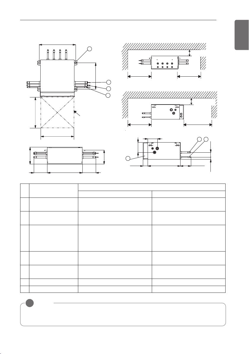
[Unit : mm(inch)]
Inspection door
(servicing space)
481(18-15/16)
345(13-19/32)
300(11-13/16)
more
300(11-13/16)
more
300(11-13/16)
more
450(17-23/32)
more
(Servicing space) (Servicing space)
(Servicing space)
(Servicing space)
1
2
3
54
6
7
453(17-27/32)
174(6-27/32)
174(6-27/32)
218(8-19/32)
182(7-5/32)
419(16-1/2)
61(2-13/32)
137(5-13/32)
124(4-7/8)
128(5-1/32)
30(1-3/16)
450(17-23/32)
450(17-23/32)
100(3-15/16) more
(Serviceing space)
100(3-15/16) more
(Serviceing space)
60(2-3/8)
No. Part Name
Description
PRHR031A/PRHR041A PRHR021A
1
Low pressure Gas pipe
connection port
Ø28.58(1-1/8) Brazing connection Ø22.2(7/8) Brazing connection
2
High pressure Gas pipe
connection port
Ø22.2(7/8) Brazing connection Ø19.05(3/4) Brazing connection
3
Liquid pipe connection
port
Ø15.88(5/8) Brazing connection
(PRHR041A)
Ø12.7(1/2) Brazing connection
(PRHR031A)
Ø9.52(3/8) Brazing connection
4
Indoor unit Gas pipe
connection port
Ø15.88(5/8) Brazing connection Ø15.88(5/8) Brazing connection
5
Indoor unit Liquid pipe
connection port
Ø9.52(3/8) Brazing connection Ø9.52(3/8) Brazing connection
6
Control box - -
7
Hanger metal M10 or M8 M10 or M8
NOTE
!
• Be sure to install the inspection door at the control box side.
• If reducers are used, servicing space must be increased equal to reducer's dimension.
22
INSTALLATION SPACE
ENGLISH
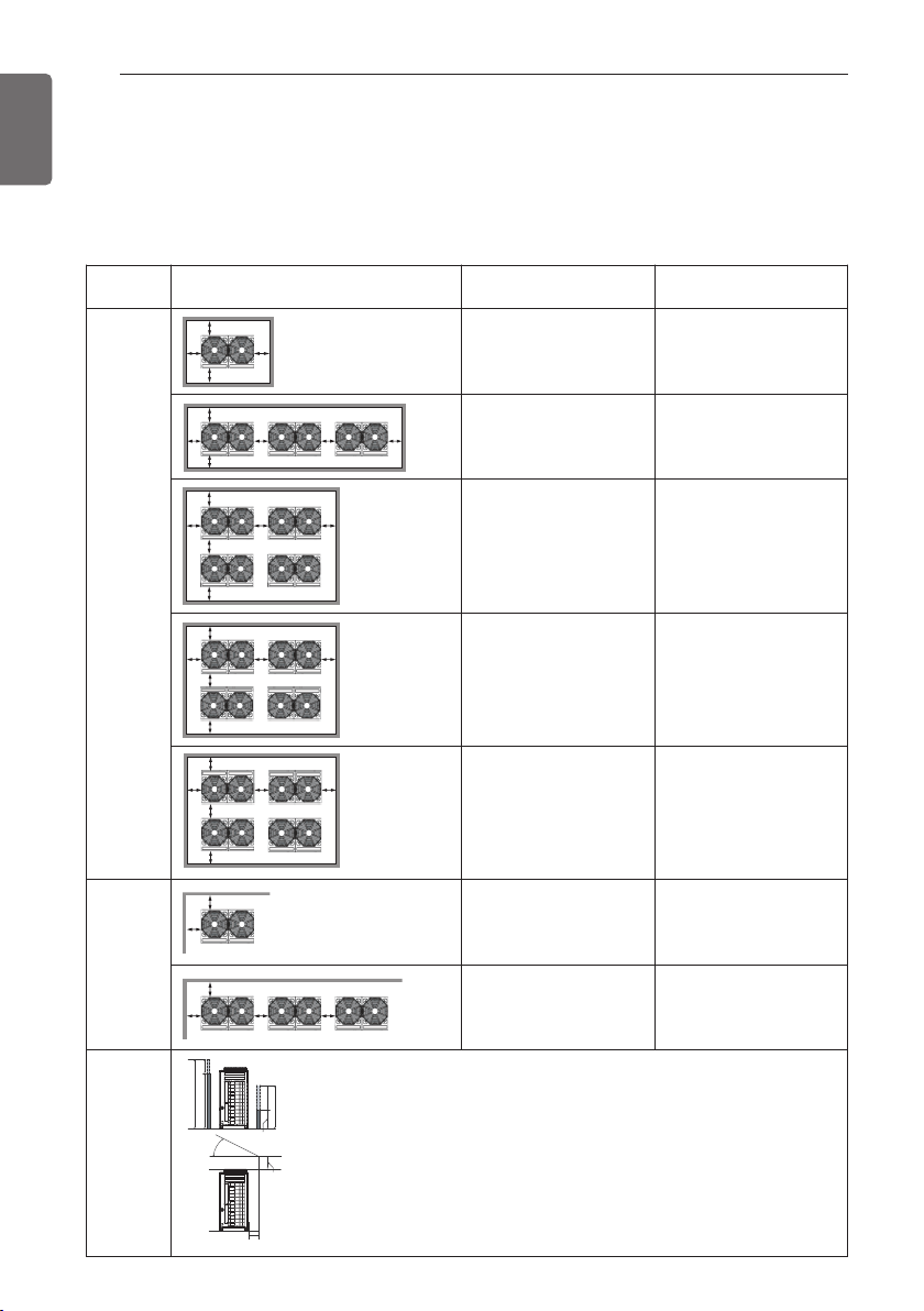
Individual Installation
During the installation of the unit, consider service, inlet, and outlet and acquire the minimum
space as shown in the figures below.
Category Installation Space
Case 1
(10mm≤Side Space≤49mm)
Case 2
(Side Space≥49mm)
4 sides
are walls
A≥10(13/32”)
B≥300(11-13/16”)
C≥10(13/32”)
D≥500(19-11/16”)
A≥50(1-31/32”)
B≥100(3-15/16”)
C≥50(1-31/32”)
D≥500(19-11/16”)
A≥10(13/32”)
B≥300(11-13/16”)
C≥10(13/32”)
D≥500(19-11/16”)
E≥20(25/32”)
A≥50(1-31/32”)
B≥100(3-15/16”)
C≥50(1-31/32”)
D≥500(19-11/16”)
E≥100(3-15/16”)
A≥10(13/32”)
B≥300(11-13/16”)
C≥10(13/32”)
D≥500(19-11/16”)
E≥20(25/32”)
F≥600(23-5/8”)
A≥50(1-31/32”)
B≥100(3-15/16”)
C≥50(1-31/32”)
D≥500(19-11/16”)
E≥100(3-15/16”)
F≥500(19-11/16”)
A≥10(13/32”)
B≥300(11-13/16”)
C≥10(13/32”)
D≥300(11-13/16”)
E≥20(25/32”)
F≥500(19-11/16”)
A≥50(1-31/32”)
B≥100(3-15/16”)
C≥50(1-31/32”)
D≥100(3-15/16”)
E≥100(3-15/16”)
F≥500(19-11/16”)
A≥10(13/32”)
B≥500(19-11/16”)
C≥10(13/32”)
D≥500(19-11/16”)
E≥20(25/32”)
F≥900(35-7/16”)
A≥50(1-31/32”)
B≥500(19-11/16”)
C≥50(1-31/32”)
B≥500(19-11/16”)
E≥100(3-15/16”)
F≥600(23-5/8”)
Only 2
sides are
walls
A≥10(13/32”)
B≥300(11-13/16”)
A≥200(7-7/8”)
B≥300(11-13/16”)
E≥400(15-3/4”)
Limita-
tions on
the height
of the wall
(Refer to 4
side walls)
AE
B
D
A
C
B
D
E
C
AE
B
F
C
D
AE
B
F
C
D
A
E
B
A
B
E
front
A E
B
D
A
C
B
D
E
C
AE
B
F
C
D
AE
B
F
C
D
A
E
B
A
B
E
front front front
AE
B
D
A
C
B
D
E
C
A E
B
F
C
D
AE
B
F
C
D
A
E
B
A
B
E
front front
front front
AE
B
D
A
C
B
D
E
C
AE
B
F
C
D
A E
B
F
C
D
A
E
B
A
B
E
front front
front front
A E
B
F
C
D
front front
front front
AE
B
D
A
C
B
D
E
C
AE
B
F
C
D
AE
B
F
C
D
A
E
B
A
B
E
front
AE
B
D
A
C
B
D
E
C
AE
B
F
C
D
AE
B
F
C
D
A
E
B
A
B
E
front front front
AE
B
D
A
C
B
D
E
C
AE
B
F
C
D
AE
B
F
C
D
A
E
B
A
B
E
h2
h1
1500mm(59-1/16”)
A
B
240mm
(9-7/16”)
50mm(1-31/32”)
45° or
more
500mm
(19-11/16”)
• The height of the wall on the front side must be 1500mm(59-1/16") or less.
• The height of the wall on the inlet side must be 500mm(19-11/16") or less.
• There is no limit to the wall on the side.
• If the height of the walls on the front and the inlet are higher than the limit, there
must be additional space on the front and the side.
- Additional Space on the inlet side by 1/2 of h1.
- Additional Space on the front side by 1/2 of h2
- h1 = B(Actual height) - 1500mm(19-11/16")
- h2 = A(Actual height) - 500mm(59-1/16")
INSTALLATION SPACE

INSTALLATION SPACE
23
ENGLISH
Seasonal wind and cautions in winter
• Sufficient measures are required in a snow area or severe cold area in winter so that product
can be operated well.
• Get ready for seasonal wind or snow in winter even in other areas.
• Install a suction and discharge duct not to let in snow or rain.
• Install the outdoor unit not to come in contact with snow directly. If snow piles up and freezes
on the air suction hole, the system may malfunction. If it is installed at snowy area, attach the
hood to the system.
• Install the outdoor unit at the higher installation console by 50cm(1.64ft) than the average
snowfall (annual average snowfall) if it is installed at the area with much snowfall.
• Where snow accumulated on the upper part of the Outdoor Unit by more than 10cm, always
remove snow for operation.
- The height of H frame must be more than 2 times the snowfall and its width shall not ex-
ceed the width of the product. (If width of the frame is wider than that of the product,
snow may accumulate)
- Don't install the suction hole and discharge hole of the Outdoor Unit facing the seasonal
wind.
CAUTION
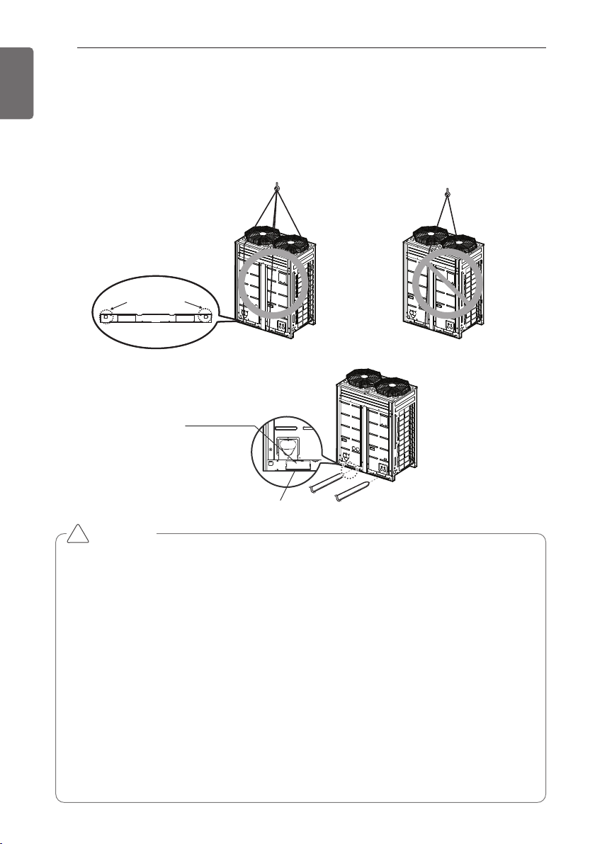
Be very careful while carrying the product.
• Do not have only one person carry product if it is more than 20 kg(44lbs).
• PP bands are used to pack some products. Do not use them as a mean for transportation
because they are dangerous.
• Do not touch heat exchanger fins with your bare hands. Otherwise you may get a cut in
your hands.
• Tear plastic packaging bag and scrap it so that children cannot play with it. Otherwise
plastic packaging bag may suffocate children to death.
• When carrying in Outdoor Unit, be sure to support it at four points. Carrying in and lifting
with 3-point support may make Outdoor Unit unstable, resulting in a fall.
• Use 2 belts of at least 8m(26.2ft) long.
• Place extra cloth or boards in the locations where the casing comes in contact with the
sling to prevent damage.
• Hoist the unit making sure it is being lifted at its center of gravity.
• When carrying the suspended, unit pass the ropes under the unit and use the two suspension
points each at the front and rear.
• Always lift the unit with ropes attached at four points so that impact is not applied to the unit.
• Attach the ropes to the unit at an angle of 40° or less.
Locking points for
transportation ropes
Forklift Carrying Guide
Forklift Carrying Hole
!
LIFTING METHOD
24
LIFTING METHOD
ENGLISH
INSTALLATION
25
ENGLISH
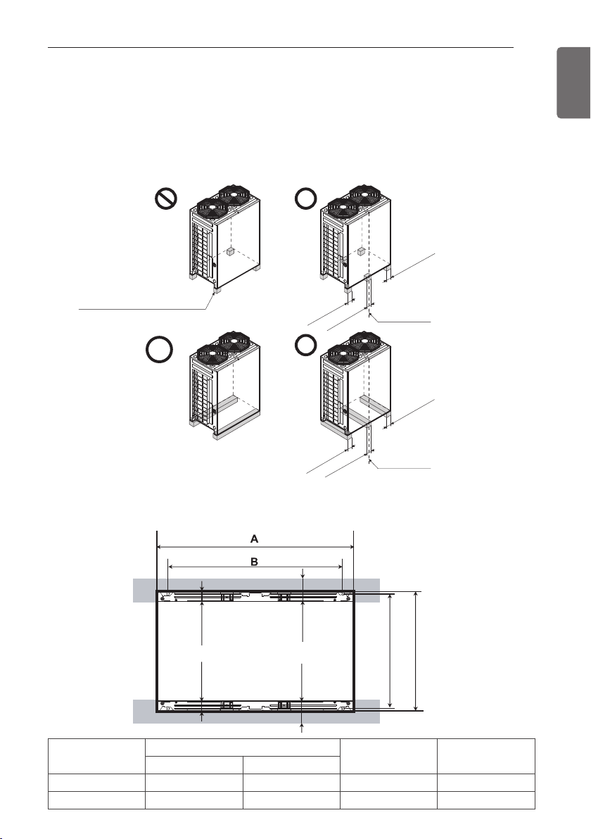
The location of the Anchor bolts
• The outdoor unit supports at the bottom shall have width of at least 100mm(3-15/16 inch) under
the Unit’s legs before being fixed.
• The outdoor unit supports should nave minimum height of 200mm(7-7/8 inch).
• Anchor bolt must be inserted at least 75mm(2-15/16 inch).
At least 100mm
(3-15/16 inch)
At least 100m
m
(3-15/16
inch)
At least 100mm
(3-15/16 inch)
At least 100mm
(3-15/16 inch)
At least 100mm
(3-15/16 inch)
At least 100mm
(3-15/16 inch)
Center of the Unit
For outdoor units should not
be supported only by the
corner supports.
Center of the Unit
730(28-3/4)
760(29-29/32)
65(2-9/16)
65(2-9/16)
Unit : mm(inch)
At least
65(2-9/16)
At least
65(2-9/16)
INSTALLATION
Chassis
Outdoor Unit Capacity
A [mm(inch)] B [mm(inch)]
Ton HP
UX2 6Ton 8HP 920(36-7/32) 792(31-3/16)
UX3 8~14Ton 10~14,18HP 1240(48-13/16) 1102(42-3/8)
Foundation for Installation
• Fix the unit tightly with bolts as shown below so that unit will not fall down due to earthquake
or gust.
• Use the H-beam support as a base support
• Noise and vibration may occur from the floor or wall since vibration is transferred through the
installation part depending on installation status. Thus, use anti-vibration materials (cushion pad)
fully (The base pad shall be more than 200mm(7.87inch)).
At least
200 (7.87)
Unit : mm(inch)
200(7.87)
200(7.87)
75(2.95)
75(2.95)
100(3.94)
Ⓐ The corner part must be fixed firmly. Otherwise,
the support for the installation may be bent.
Ⓑ Get and use M10 Anchor bolt.
Ⓒ Put Cushion Pad between the outdoor unit and
ground support for the vibration protection in wide
area.
Ⓓ Space for pipes and wiring (Pipes and wirings for
bottom side)
Ⓔ H-beam support
Ⓕ Concrete support
CAUTION
• Be sure to remove the Pallet(Wood Support) of the
bottom side of the outdoor unit Base Pan before fix-
ing the bolt. It may cause the unstable state of the
outdoor settlement, and may cause freezing of the
heat exchanger resulting in abnormal operations.
• Be sure to remove the Pallet(Wood Support) of the
bottom side of the outdoor unit before welding.
Not removing Pallet(Wood Support) causes hazard
of fire during welding.
WARNING
• Install where it can sufficiently support the weight of the outdoor unit.
If the support strength is not enough, the outdoor unit may drop and hurt people.
• Install where the outdoor unit may not fall in strong wind or earthquake.
If there is a fault in the supporting conditions, the outdoor unit may fall and hurt people.
• Please take extra cautions on the supporting strength of the ground, water outlet treat-
ment(treatment of the water flowing out of the outdoor unit in operation), and the pas-
sages of the pipe and wiring, when making the ground support.
• Do not use tube or pipe for water outlet in the Base pan. Use drainage instead for water
outlet. The tube or pipe may freeze and the water may not be drained.
Pallet(Wood Support)
- Remove before Installation
!
!
26
INSTALLATION
ENGLISH
INSTALLATION
27
ENGLISH
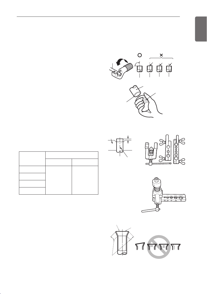
Main cause of gas leakage is defect in flaring work. Carry out correct flaring work in the following
procedure.
Cut the pipes and the cable
- Use the accessory piping kit or the pipes pur-
chased locally.
- Measure the distance between the indoor
and the outdoor unit.
- Cut the pipes a little longer than measured
distance.
- Cut the cable 1.5m(4.92ft) longer than the
pipe length.
Burrs removal
- Completely remove all burrs from the cut
cross section of pipe/tube.
- Put the end of the copper tube/pipe to down-
ward direction as you remove burrs in order
to avoid to let burrs drop in the tubing.
Flaring work
- Carry out flaring work using flaring tool as
shown below.
Firmly hold copper tube in a bar(or die) as in-
dicated dimension in the table above.
Check
- Compare the flared work with figure below.
- If flare is noted to be defective, cut off the
flared section and do flaring work again.
Copper
tube
90
Slanted Uneven Rough
Pipe
Reamer
Point down
Bar
Copper pipe
"A"
<Wing nut type>
<Clutch type>
Inclined
Inside is shining without scratches.
Smooth all round
Even length
all round
Surface
damaged
Cracked Uneven
thickness
= Improper flaring =
Preparation of Piping
Pipe diameter
Inch (mm)
A inch (mm)
Wing nut type Clutch type
Ø1/4 (Ø6.35)
0.04~0.07
(1.1~1.8)
0~0.02
(0~0.5)
Ø3/8 (Ø9.52)
Ø1/2 (Ø12.7)
Ø5/8 (Ø15.88)
Flare shape and flare nut tightening torque
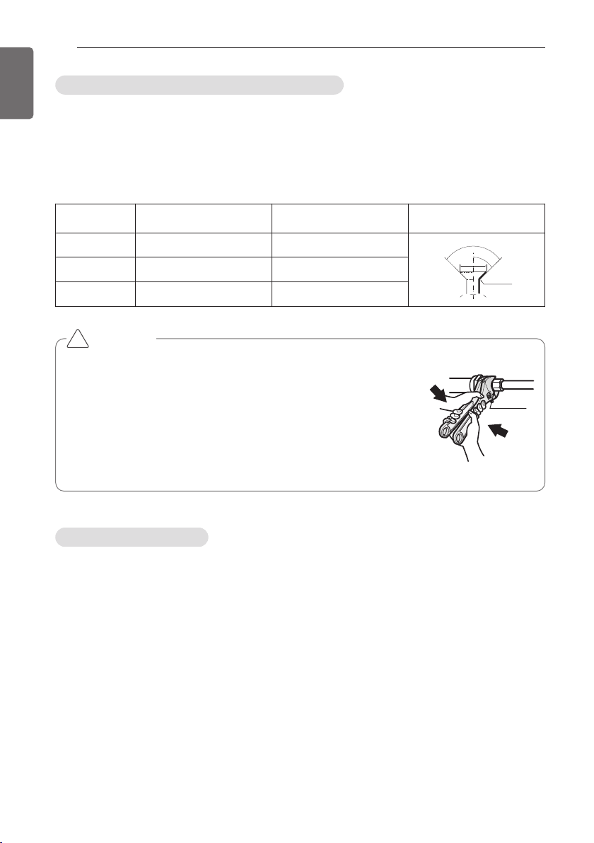
Opening shutoff valve
Precautions when connecting pipes
- See the following table for flare part machining dimensions.
- When connecting the flare nuts, apply refrigerant oil to the inside and outside of the flares and
turn them three or four times at first. (Use ester oil or ether oil.)
-
See the following table for tightening torque.(Applying too much torque may cause the flares to crack.)
- After all the piping has been connected, use nitrogen to perform a gas leak check.
1 Remove the cap and turn the valve counter clockwise with the hexagon wrench.
2 Turn it until the shaft stops.
Do not apply excessive force to the shutoff valve. Doing so may break the valve body, as the
valve is not a backseat type. Always use the special tool.
3 Make sure to tighten the cap securely.
pipe size
[mm(inch)]
Tightening Torque
N·m(lbs ·ft)
A [mm(inch)] flare shape
Ø9.52(3/8) 38±4(28±3.0) 12.8(0.5)~13.2(0.52)
90
2
45
2
A
R=0.4~0.8
Ø12.7(1/2) 55±6(41±4.4) 16.2(0.64)~16.6(0.65)
Ø15.88(5/8) 75±7(55±5.2) 19.3(0.76)~19.7(0.78)
CAUTION
• Always use a charge hose for service port connection.
• After tightening the cap, check that no refrigerant leaks are present.
• When loosening a flare nut, always use two wrenches in
combination, When connecting the piping, always use a spanner and
torque wrench in combination to tighten the flare nut.
• When connecting a flare nut, coat the flare(inner and outer faces)
with oil for R410A(PVE) and hand tighten the nut 3 to 4 turns as the
initial tightening.
Union
!
28
INSTALLATION
ENGLISH
INSTALLATION
29
ENGLISH
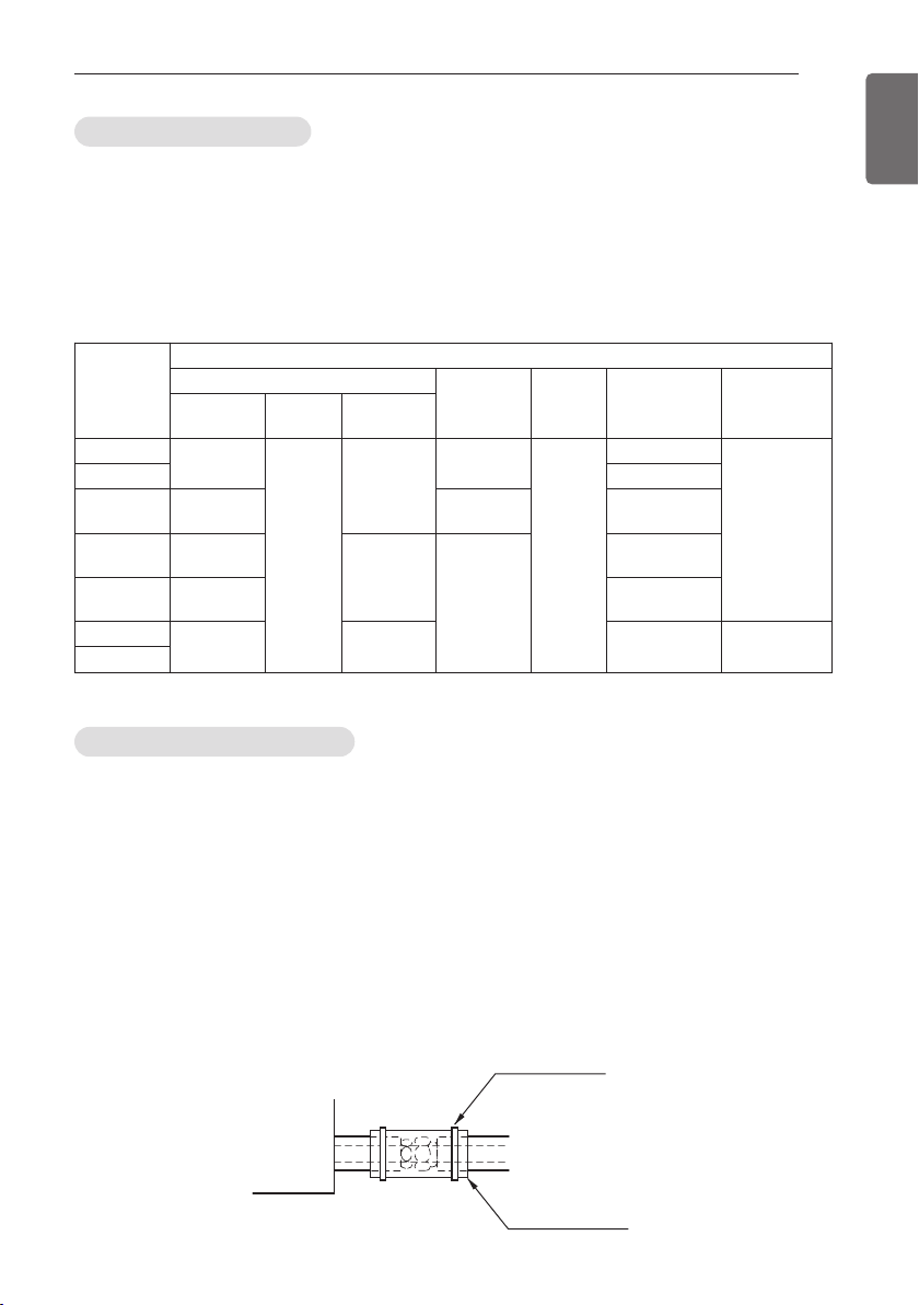
Insulation of shutoff valve
1 Use the heat insulation material for the refrigerant piping which has an excellent heat-resis-
tance (over 248°F).
2 Precautions in high humidity circumstance:
This air conditioner has been tested according to the "ISO Conditions with Mist" and con-
firmed that there is not any default. However, if it is operated for a long time in high humid at-
mosphere (dew point temperature: more than 73.4°F), water drops are liable to fall. In this
case, add heat insulation material according to the following procedure:
- Heat insulation material to be prepared... EPDM (Ethylene Propylene Diene Methylene)-over
248°F the heat-resistance temperature.
- Add the insulation over 10mm(0.39 inch) thickness at high humidity environment.
Indoor unit
Thermal insulator
(accessory)
Fastening band
(accessory)
Refrigerant piping
Closing shutoff valve
1 Remove the cap and turn the valve clockwise with the hexagon wrench.
2 Securely tighten the valve until the shaft contacts the main body seal.
3 Make sure to tighten the cap securely.
* For the tightening torque, refer to the table on the below.
Tightening torque
Shut off
valve size
[mm(inch)]
Tightening torque N·m(lbs ·ft)(Turn clockwise to close)
Shaft(valve body)
Cap (Valve
lid)
Service
port
Flare nut
Gas line pip-
ing attached
to unit
Closed Opened
Hexagonal
wrench
Ø6.35(1/4)
6.0 ±0.6
(4.4±0.4)
5.0 ±0.0
(3.7±0.4)
4mm
(0.16inch)
17.6±2.0
(13.0±1.5)
12.7±2
(9.4±1.5)
16±2(12±1.5)
-
Ø9.52(3/8) 38±4(28±3.0)
Ø12.7(1/2)
10.0 ±1.0
(7.4±0.7)
20.0±2.0
(14.8±1.5)
55±6(41±4.4)
Ø15.88(5/8)
12.0 ±1.2
(8.9±0.9)
5mm
(0.24inch)
25.0±2.5
(18.4±1.8)
75±7 (55±5.1)
Ø19.05(3/4)
14.0 ±1.4
(10.3±1.0)
110±10
(81.1±7.4)
Ø22.2(7/8)
30.0 ±3.0
(22.1±2.2)
8mm
(0.31inch)
-
25±3.0
(18.5±2.2)
Ø25.4(1.0)
30
INSTALLATION
ENGLISH
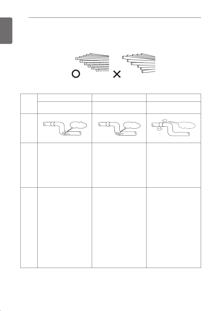
Plumbing materials and storage methods
Pipe must be able to obtain the specified thickness and should be used with low impurities.
Also when handling storage, pipe must be careful to prevent a fracture, deformity and wound.
Should not be mixed with contaminations such as dust, moisture.
Refrigerant piping on three principles
Drying Cleanliness Airtight
Should be no moisture inside No dust inside.
There is no refrigerant
leakage
Items
Moisture
Dust
Leakage
Cause
failure
- Significant hydrolysis of
refrigerant oil
- Degradation of refrigerant
oil
- Poor insulation of the
compressor
- Do not cold and warm
- Clogging of EEV, Capillary
- Degradation of refrigerant
oil
- Poor insulation of the
compressor
- Do not cold and warm
- Clogging of EEV, Capillary
- Gas shortages
- Degradation of refrigerant
oil
- Poor insulation of the
compressor
- Do not cold and warm
Counter
measure
- No moisture in the pipe
- Until the connection is
completed, the plumbing
pipe entrance should be
strictly controlled.
- Stop plumbing at rainy day.
- Pipe entrance should be
taken side or bottom.
- When removal burr after
cutting pipe, pipe entrance
should be taken down.
- Pipe entrance should be
fitted cap when pass
through the walls.
- No dust in the pipe.
- Until the connection is
completed, the plumbing
pipe entrance should be
strictly controlled.
- Pipe entrance should be
taken side or bottom.
- When removal burr after
cutting pipe, pipe entrance
should be taken down.
- Pipe entrance should be
fitted cap when pass
through the walls.
- Airtightness test should
be.
- Brazing operations to
comply with standards.
- Flare to comply with
standards.
- Flange connections to
comply with standards.
INSTALLATION
31
ENGLISH
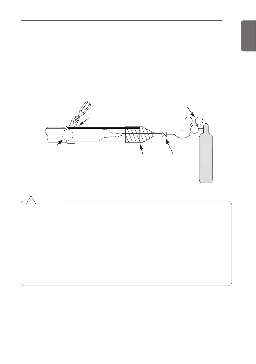
Nitrogen substitution method
Welding, as when heating without nitrogen substitution a large amount of the oxide film is
formed on the internal piping.
The oxide film is a caused by clogging EEV, Capillary, oil hole of accumulator and suction hole of
oil pump in compressor.
It prevents normal operation of the compressor.
In order to avoid this problem, Welding should be done after replacing air by nitrogen gas.
When welding plumbing pipe, the work is required.
1 Always use the nitrogen.(not use oxygen, carbon dioxide, and a Chevron gas):
Please use the following nitrogen pressure Pressure 0.02Mpa (2.9psi) less
Oxygen – Promotes oxidative degradation of refrigerant oil.
Because it is flammable, it is strictly prohibited to use
Carbon dioxide – Degrade the drying characteristics of gas
Chevron Gas – Toxic gas occurs when exposed to direct flame.
2 Always use a pressure reducing valve.
3. Please do not use commercially available antioxidant.
The residual material seems to be the oxide scale is observed.
In fact, due to the organic acids generated by oxidation of the alcohol contained in the anti-
oxidants, ants nest corrosion occurs. (causes of organic acid alcohol + copper + water +
temperature)
CAUTION
!
Regulator
Nitrogen gas Pressure
0.02Mpa (2.9psi) less
Auxiliary valve
Taping
(Should not
contain air)
Welding Point
Note) should not block the outlet side.
When the internal pressure in pipe is abo
ve the atmospheric pressure, pinhole is o
ccurred and it is a leakage cause.
Oxide scale
Nitrogen
32
REFRIGERANT PIPING INSTALLATION
ENGLISH
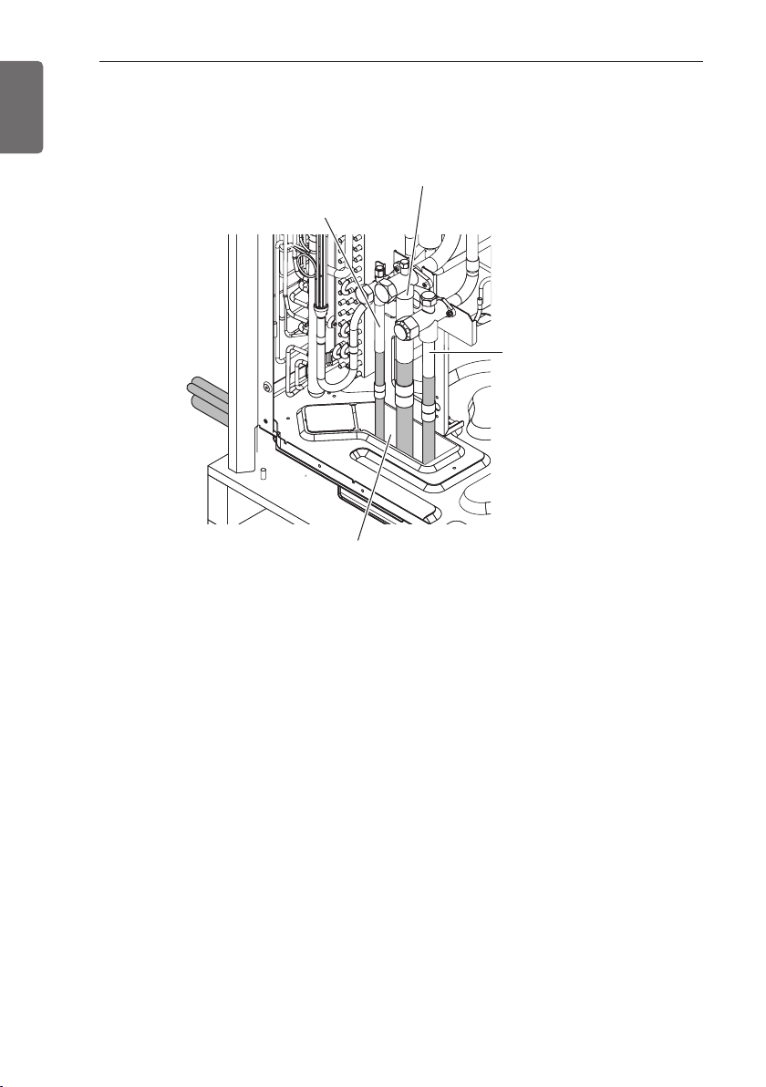
Precautions on Pipe connection / Valve operation
Pipe connection is done by connecting from the end of the pipe to the branching pipes, and the
refrigerant pipe coming out of the outdoor unit is divided at the end to connect to each indoor
unit and HR unit. Flare connection for the indoor unit, and welding connection for the outdoor
pipe and the branching parts. (Including HR unit)
- Use hexagonal wrench to open/close the valve.
Low Pressure Gas pipe
Service Port
Liquid pipe
High Pressure Gas pipe
Please block the pipe knock outs of the front and side panels after installing the pipes.
(Animals or foreign objects may be brought in to damage wires.)
WARNING
• Always careful not to leak the refrigerant during welding.
• The refrigerant generates poisonous gas harmful to human body if combusted.
• Do not perform welding in a closed space.
• Be sure to close the cap of the service port to prevent gas leakage after the work.
!
REFRIGERANT PIPING INSTALLATION
CAUTION
!
REFRIGERANT PIPING INSTALLATION
33
ENGLISH
Connection of Outdoor units
(Unit : mm(inch))
2 Unit
3 Unit
ARCNB21
ARCNB31
C
C
C
C
C
Outdoor units Model
Low Pressure Gas Pipe
High Pressure Gas PipeLiquid Pipe
O.D25.4(1)
I.D22.2(7/8)
I.D19.05(3/4)
120(4-23/32)
X2
O.D19.05(3/4)
I.D15.88(5/8)
I.D12.7(1/2)
110(4-11/32)
O.D25.4(1)
I.D22.2(7/8)
80(3-5/32)
O.D12.7(1/2)
I.D9.52(3/8)
70(2-3/4)
453(17-27/32)
491(19-9/32)
111
(4-3/8)
I.D28.58(1-1/8)
I.D34.9(1-3/8)
I.D28.58(1-1/8)
I.D31.8(1-1/4)
I.D25.4(1)
I.D31.8(1-1/4)
I.D25.4(1)
I.D28.58(1-1/8)
I.D31.8(1-1/4)
130(5-1/8)
416(16-3/8)
408(16-1/16)
111(4-3/8)
I.D.38.1(1-1/2)
I.D.34.9(1-3/8)
O.D.34.9(1-3/8)
I.D.41.3(1-5/8)
I.D.31.8(1-1/4)
I.D.28.58(1-1/8)
I.D.28.58(1-1/8)
I.D.28.58(1-1/8)
I.D.22.2(7/8)
331(13-1/32)
314(12-3/8)
O.D.19.05(3/4)
I.D.19.05(3/4)
I.D.15.88(5/8)
I.D.15.88(5/8)
I.D.15.88(5/8)
I.D.22.2(7/8)
I.D.12.7(1/2)
I.D.12.7(1/2)
I.D.9.52(3/8)
70(2-3/4)
83(3-9/32)
O.D.19.05(3/4)
O.D.19.05(3/4)
I.D.15.88(5/8)
I.D.22.2(7/8)
I.D.12.7(1/2)
334(13-5/32)
281(11-1/16)
83(3-9/32)
I.D.34.9(1-3/8)
O.D.34.9(1-3/8)
125(4-29/32)
406(16)
353(13-29/32)
111(4-3/8)
I.D34.9(1-1/8)
I.D.28.58(1-1/8)
I.D.41.3(1-5/8)
I.D38.1(1-1/2)
I.D.41.3(1-5/8)
471(18-17/32)
517(20-11/32)
125(4-29/32)
I.D41.3(1-5/8)
I.D38.1(1-1/2)
I.D38.1(1-1/2)
I.D34.9(1-3/8)
I.D34.9(1-3/8)
I.D34.9(1-3/8)
I.D28.58(1-1/8)
I.D19.05
(3/4)
I.D22.2(7/8)
O.D28.58(1-1/8)
120(4-23/32)
I.D19.05
(3/4)
I.D22.2(7/8)
O.D28.58(1-1/8)
120(4-23/32)
O.D15.88(5/8) I.D9.52(3/8)
I.D12.7(1/2)
110(4-11/32)
O.D12.7(1/2)
I.D6.35(1/4)
I.D9.52(3/8)
110(4-11/32)
O.D.19.05(3/4)
I.D.12.7(1/2)
I.D.15.88(5/8)
X2
110(4-11/32)
130(5-1/8)
I.D12.7(1/2)
I.D19.05
(3/4)
I.D22.2(7/8)
I.D41.3(1-5/8)
I.D38.1(1-1/2)
I.D41.3(1-5/8)
O.D34.9(1-3/8)
O.D38.1(1-1/2)
O.D28.58(1-1/8)
O.D15.88(5/8)
90(3-17/32)
70(2-3/4)
120(4-23/32)
120(4-23/32)
I.D19.05(3/4)
I.D15.88(5/8)
O.D22.2(7/8)
I.D28.58(1-1/8)
I.D22.2(7/8)
Y branch
A
B
To outdoor unit
To branch piping or indoor unit
A
B
Facing
upwards
Facing
downwards
Within ± 3° Within ± 3°
Viewed from point A
in direction of arrow
Within +/- 10°
For more information, refer accessory installation manual.
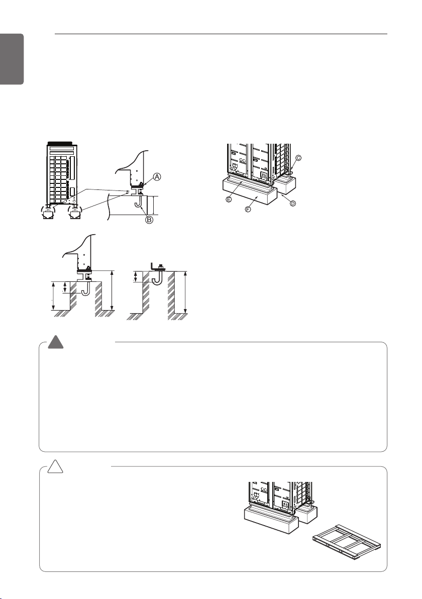
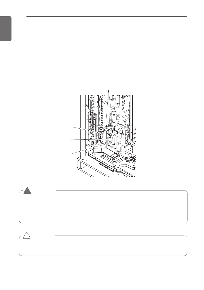
Installation procedure for HR unit
1 Using an insert-hole-in- anchor, hang the hanging bolt.
2 Install a hexagon nut and a flat washer (locally-procured)to the hang-
ing bolt as shown in the figure in the bottom, and fit the main unit to
hang on the hanger metal.
3 After checking with a level that the unit is level, tighten the hexagon
nut.
* The tilt of the unit should be within ±5° in front/back and left/right.
4 This unit should be installed suspended from ceiling and side A should
always be
facing up.
5 Insulate not used pipes completely as shown in the figure.
Six-sided Nut
(M10 or M8)
Hanger metal
Hanger metal
Hanger metal
Flat washer
Flat washer
Flat washer
(M10)
Hanging bolt
Hanging bolt
Hanging bolt
(M10 or M8)
A
Insulation
34
REFRIGERANT PIPING INSTALLATION
ENGLISH
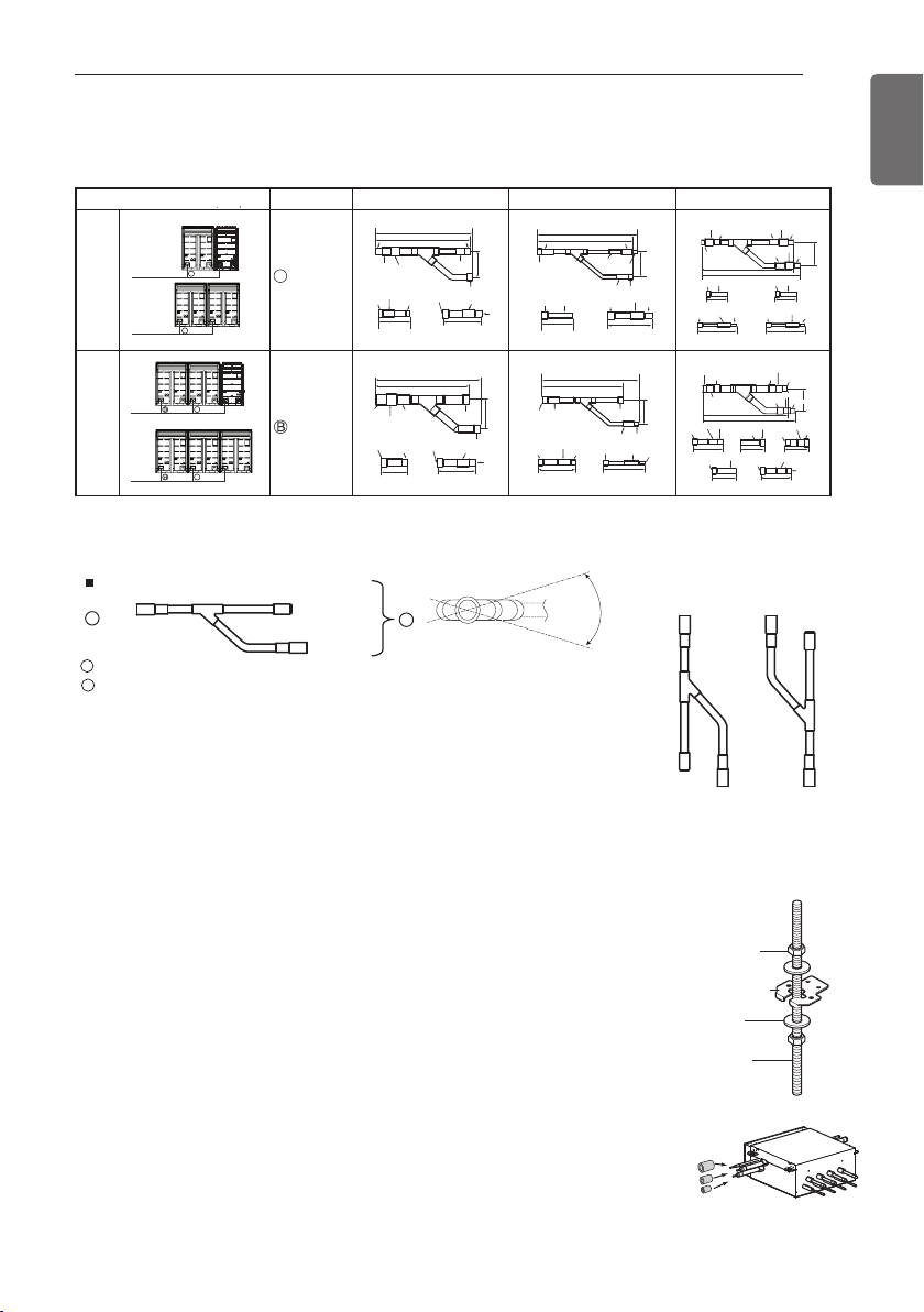
Installation of Outdoor Unit, HR Unit and Indoor Unit Refriger-
ant Pipe
3 pipes are connected to the HR unit from the outdoor unit, classified into liquid pipe, low pres-
sure gas pipe and high pressure gas pipe depending on status of refrigerant passing through the
pipe.
You must connect 3 pipes from outdoor unit to HR unit.
For connection between indoor unit and HR unit, you must connect both liquid pipe and gas pipe
from the HR unit to the indoor unit. In this case, connect them to the indoor unit starting from
No.1 connection port of the HR unit (the port number is displayed on ports of the HR unit). Use
auxiliary flare as annexed parts in connection to the indoor unit.
Gas pipe
Gas pipe
Liquid pipe
Liquid pipe
HR Unit
1
2
3
4
Low pressure
Gas pipe
Liquid pipe
High pressure
Gas pipe
Whenever connecting the indoor units with the HR unit, install the indoor units in numerical order
from No.1.
Ex) In case of installing 3 indoor units : No. 1, 2, 3 (O), No. 1, 2, 4 (X), No.1, 3, 4 (X), No.2, 3, 4 (X).
CAUTION
!
Gas pipe Ø15.88 (5/8)
Liquid pipe Ø9.52 (3/8)
Brazing Type
Liquid pipe
Liquid pipe
Low pressure gas pipe
Low pressure gas pipe
High pressure gas pipe
High pressure gas pipe
Liquid pipe
Low pressure gas pipe
High pressure gas pipe
(Brazing Type)
WARNING
Before brazing work, remove gas in the HR Unit by cutting the three pipes in the small circles on
the figure.
If not, it may cause injuries.
Remove the caps before connecting pipes.
!
REFRIGERANT PIPING INSTALLATION
35
ENGLISH
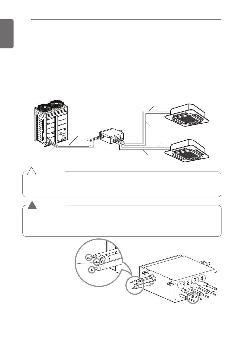
Type of HR Unit
Select an HR unit according to the number of the indoor units to be installed. HR units are classi-
fied into 3 types by the number of connectable indoor units.
Ex) Installation of 6 indoor units
Consists of HR unit for 4 branches and HR unit for 2 branches.
Type of HR Unit
Select an HR unit according to the number of the indoor units to be installed. HR units are classi-
fied into 3 types by the number of connectable indoor units.
Ex) Installation of 6 indoor units
Consists of HR unit for 4 branches and HR unit for 2 branches.
PRHR031A(3 branches)PRHR021A(2 branches) PRHR041A(4 branches)
1
2
3
1
2
1
3
2
4
1
st
HR Unit 2
nd
HR Unit
1 2 3 4
B8
(96k) (28k)
BG
1 2 3 4
B8
(76k)(21k)
BH
Joint Method of HR Unit (Big Duct : ARNU763B8-, ARNU963B8-)
Joint Method is required when B5/B8 chassis is installed. In Joint Method, two neighboring out-
lets of one HR unit are linked by Y branch pipe and connected to one indoor unit.
Gas pipe Ø15.88 (5/8)
Liquid pipe Ø9.52 (3/8)
Brazing Type
1
2
3
4
Remove caps on
The brazing part.
Liquid pipe
Low pressure gas pipe
High pressure gas pipe
Unit : mm(inch)
HR unit PRHR021A PRHR031A PRHR041A
Low pressure gas pipe Ø22.2(7/8) Ø28.58(1-1/8) Ø28.58(1-1/8)
High pressure gas pipe Ø19.05(3/4) Ø22.2(7/8) Ø22.2(7/8)
Liquid pipe Ø9.52(3/8) Ø12.7(1/2) Ø15.88(5/8)
36
REFRIGERANT PIPING INSTALLATION
ENGLISH
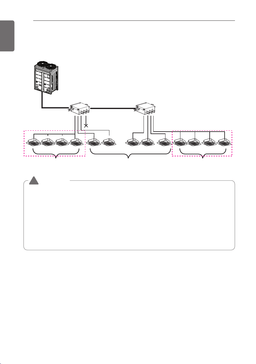
Installation of Zoning Control
Some indoor unit can be connected to one port of HR unit.
HR unit HR unit
sealing
Changeover under control Auto changeover Changeover under control
Zoning control group 1 Zoning control group 2
(Max. 8 Indoor Units)
(Max. 8 Indoor Units)
WARNING
• A branch pipe of HR unit allows up to 14.5kW(48kBtu/h) based on cooling capacity of the
indoor unit. (up to 14.5kW(48kBtu/h) for max installation)
• The maximum total capacity of indoor units connected to a PRHR041 HR unit is
58kW(192kBtu/h).
• The maximum number of indoor units connected to a PRHR041 HR unit are 32 indoor
units. (The Maximum indoor units per a branch pipe of HR unit are 8 indoor units)
• There is not operate “Auto-changeover” & “Mode override” function in the zoning group.
• When there are operating indoor units on cooling(heating) mode, another indoor units
aren’t changed on heating(cooling) mode in the zoning group.
!
REFRIGERANT PIPING INSTALLATION
37
ENGLISH
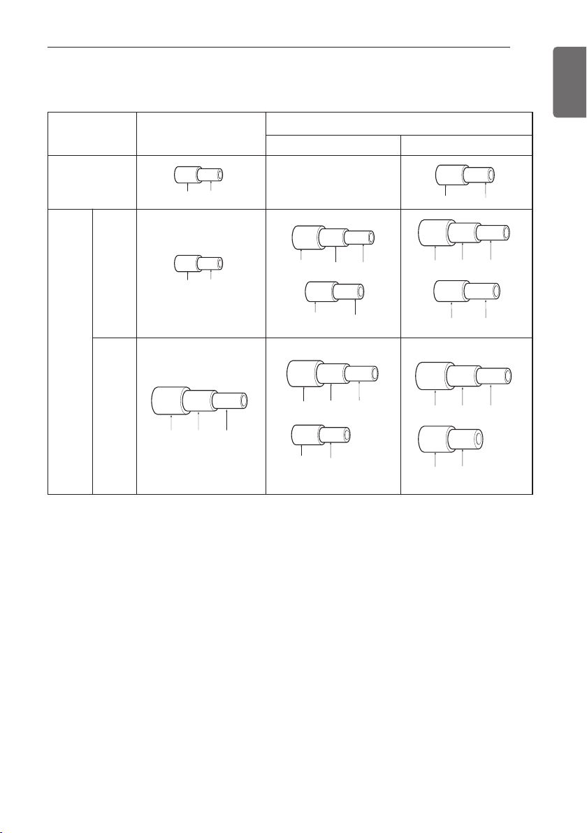
[Reducers for indoor unit and HR unit]
Unit : mm(inch)
Models
High pressure
-
Gas pipe
Low pressure
Liquid pipe
Indoor unit
reducer
HR unit
reducer
PRHR021A
OD22.2(7/8) Ø19.05(3/4) Ø15.88(5/8)
OD15.88(5/8) Ø
12.7(1/2)
Ø6.35(1/4)OD9.52(3/8)
Ø6.35(1/4)OD9.52(3/8)
OD19.05(3/4) Ø15.88(5/8)
OD12.7(1/2) Ø9.52(3/8)
Ø12.7(1/2)
OD22.2(7/8) Ø19.05(3/4) Ø15.88(5/8)
OD15.88(5/8) Ø12.7(1/2)
PRHR031A/
PRHR041A
OD19.05(3/4) Ø15.88(5/8)
OD28.58(1-1/8) Ø22.2(7/8) Ø19.05(3/4)
OD15.88(5/8) Ø12.7(1/2) Ø9.52(3/8)
OD15.88(5/8) Ø12.7(1/2)
38
PIPE CONNECTIONS BETWEEN INDOOR AND OUTDOOR UNIT
ENGLISH
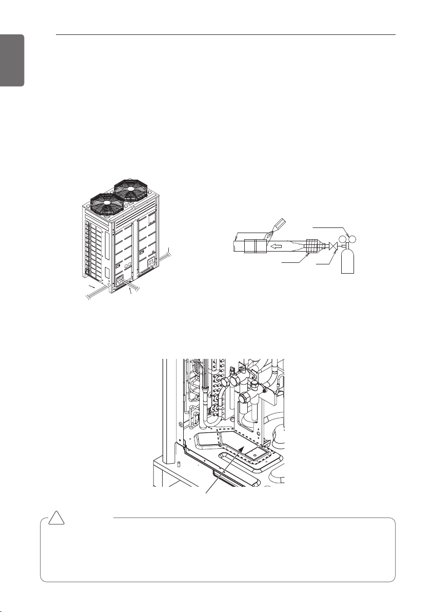
- Pipe connections can be done on the front side or on the side according to the installation envi-
ronments.
- Be sure to let 0.2kgf/cm
2
(0.284lbs/in
2
) Nitrogen flow in the pipe when welding.
- If Nitrogen was not flown during welding, many oxidized membranes may form inside the pipe
and disturb the normal operations of valves and condensers.
Left Side Pipe
Draw Out
Front Pipe Draw Out
Right Side Pipe
Draw Out
Refrigerant Pipe
Regulator
Nitrogen
Taping
Valve
Nitrogen
Nitrogen
Direction
Direction
Nitrogen
Direction
Preparation Work
- Use Knock Outs of Base Pan of the outdoor unit for Left/Right or Bottom pipe drawing outs.
Removal Area for Liquid/Gas pipe
bottom side connections.
CAUTION
• Do not give damage to the pipe/base during the Knock Out work.
• Proceed to pipe work after removing burr after Knock Out work.
• Perform sleeve work to prevent damage to the wire when connecting wires using knock
Outs.
!
PIPE CONNECTIONS BETWEEN INDOOR AND
OUTDOOR UNIT
PIPE CONNECTIONS BETWEEN INDOOR AND OUTDOOR UNIT
39
ENGLISH
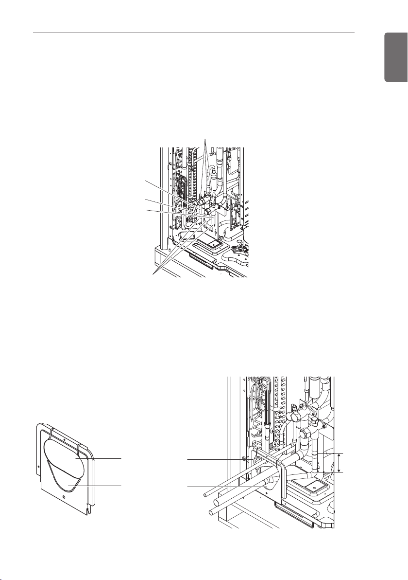
Remove leakage prevention cap
• Remove the leakage prevention cap attached to the outdoor unit service valve before pipe
work.
• Proceed the leakage prevention cap removal as follows:
- Verify whether the liquid/gas pipes are locked.
- Extract remaining refrigerant or air inside using the service port.
- Remove the leakage prevention cap
Leakage Prevention Cap
Low Pressure Gas pipe
Service Port
Liquid pipe
High Pressure Gas pipe
Pipe Drawing Out during Single / Series connection
Method of drawing out pipes on the front side
- Proceed with the pipe work as shown in the below figure for front side pipe drawing out.
Pipe Knock Out
for High Pressure
Gas pipe
Pipe Knock Out for
Liquid/Gas pipes
80mm
(3.15in)
40
PIPE CONNECTIONS BETWEEN INDOOR AND OUTDOOR UNIT
ENGLISH
Method of drawing out pipes on the bottom side
- Drawing out common pipe through side panel
Liquid pipe
Low Pressure Gas pipe
High Pressure
Gas pipe
Remove pipe knock out
PIPE CONNECTIONS BETWEEN INDOOR AND OUTDOOR UNIT
41
ENGLISH
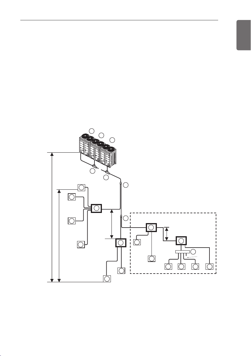
Refrigerant piping system
Refrigerant Pipe Connection
3 Outdoor Units
Example : 12 Indoor Units connected
Ⓐ : Outdoor Unit
Ⓑ : Y branch
Ⓓ : Indoor Unit
Ⓔ : Connection branch pipe between Outdoor units : ARCNB31
Ⓕ : Connection branch pipe between Outdoor units : ARCNB21
Ⓖ : Header
Ⓗ : HR Unit
A1
H1
D
1
2
D
D
D
3
4
E1
E2
A
F3
C1
B
C2
C3
*
B1
B2
A2
A3
a
b
c
d
e
g
j
k
x
l
m
n
sealing
f
i
H
h
"a"
"b"
F2
F1
E
H2
H4
G
H3
Master
Slave 1
Slave 2
■ Case 1 ("a")
: Maximum height is 15m(49ft) if you install with Y branch.
■ Case 2 ("b")
: Maximum height is 5m(16ft) in serial connection of HR units.
ODU Capacity
Master ≥ Slave1 ≥ Slave 2
D
5
D
6
D
7
D
8
D
10
D
9
D
11
D
12
Refrigerant pipe diameter from branch to branch (B,C)
• * : Assume equivalent pipe length of Y branch to be 1.64ft, that of header to be 3.3ft,
calculation purpose
• it is recommended that indoor unit is installed at lower position than the header.
• ** : Conditional application
L
Longest pipe length *Equivalent pipe length
A+B+C3+k ≤150m(200m**)
[(492ft(656ft**)]
A+B+C3+k ≤175m(225m**)
[(574ft(738ft**)]
l
Longest pipe length after 1st branch
B+C+D+e ≤ 40m(90m**) [131ft(295ft)]
H
Difference in height (Outdoor Unit ÷ Indoor Unit)
H ≤ 110m(361ft)
h
Difference in height (Indoor Unit ÷ Indoor Unit)
h ≤ 40m(131ft)
h1
Difference in height (Outdoor Unit ÷ Outdoor Unit)
h1 ≤ 5m(16.4ft)
"a", "b"
Difference in height(HR unit ÷ HR unit)
a ≤ 15m(49ft) , b ≤ 5m(16ft)
WARNING
* : Serial connection of HR units : Capacity sum of indoor units ≤ 192.4 kBtu/hr
• Refer to the HR unit PCB part for the valve group control setting.
• It is recommended that difference in pipe lengths between an HR unit and indoor units, for
example difference in length of a, b, c, and d, be minimized. The larger difference in pipe
lengths, the more different performance between indoor units.
• Piping length from outdoor branch to outdoor unit ≤ 10m(33ft), equivalent length : max
13m(43ft) (for 14HP or more)
* If the large capacity indoor units (Over 5 HP; using over Ø15.88(5/8)/9.52(3/8) are installed,
it should be used the Valve Group setting
!
42
PIPE CONNECTIONS BETWEEN INDOOR AND OUTDOOR UNIT
ENGLISH
Downward indoor unit total
capacity [kW(Btu/h)]
Liquid pipe
[mm(inch)]
Gas pipe [mm(inch)]
Low pressure High pressure
≤ 5.6(19,100)
Ø6.35(1/4) Ø12.7(1/2) Ø9.52(3/8)
< 16.0 (54,600) Ø9.52(3/8) Ø15.88(5/8) Ø12.7(1/2)
≤ 22.4(76,400)
Ø9.52(3/8) Ø19.05(3/4) Ø15.88(5/8)
< 33.6(114,700) Ø9.52(3/8) Ø22.2(7/8) Ø19.05(3/4)
< 50.4(229,000) Ø12.7(1/2) Ø28.58(1-1/8) Ø22.2(7/8)
< 67.2(229,400) Ø15.88(5/8) Ø28.58(1-1/8) Ø22.2(7/8)
< 72.8(210,600) Ø15.88(5/8) Ø34.9(1-3/8) Ø28.58(1-1/8)
< 100.8(344,000) Ø19.05(3/4) Ø34.9(1-3/8) Ø28.58(1-1/8)
< 173.6(592,500) Ø19.05(3/4) Ø41.3(1-5/8) Ø34.9(1-3/8)
Total pipe length = A+B+C1+C2+C3+a+b+c+d+e+f+g+i+j+k+l+m+n ≤ 1,000m(3,280ft)
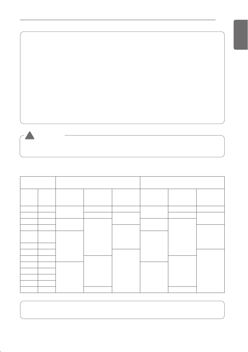
PIPE CONNECTIONS BETWEEN INDOOR AND OUTDOOR UNIT
43
ENGLISH
• * : ARUB145
*
TE4(14HP, 12Ton), ** : ARUB169
*
TE4(18HP, 14Ton)
• If available on site, it use this size. Otherwise it can't be increased.
WARNING
When the equivalent length between a outdoor and the farthest indoor unit
is 90m(295ft) or more, main pipe(A) must be increased one grade.
!
(**) Conditional Application(Incase of D12 is the farthest indoor)
Below condition must be satisfied for 40m(131ft) ~ 90m(295ft) piping length after first branch.
1) Diameter of pipes between first branch and the last branch should be increased by one
step, except if the pipe diameter B,C3 is same as Diameter A(Main pipe diameter)
Ø6.35(1/4) ’ Ø 9.52(3/8) ’ Ø 12.7(1/2) ’ Ø 15.88(5/8) ’ Ø 19.05(3/4) ’ Ø 22.2(7/8) ’
Ø 25.4*(1), Ø 28.58(1-1/8) ’ Ø 31.8*(1-1/4), Ø 34.9(1-3/8) ’ Ø 38.1*(1-1/2)
* : If available on site, it use this size. Otherwise it can't be increased.
2) While calculating total refrigerant piping length, pipe B,C3 length should be calculated twice.
A + B x 2 + C3 x 2 + C1 + C2 + a + b + c + d + e + f + g + i + j + k + l + m + n ≤
1,000m(3,280ft)
3) Length of pipe from each indoor unit to the closest HR Unit (a,b,c,d,e,e,g,i,j,k,l,m,n) ≤
40m(131ft)
4) [Length of pipe from outdoor unit to the farthest indoor unit D12 (B+C3+K)]
- [Length of pipe outdoor unit to the closest indoor unit D1 (C1+a)] ≤ 40m(131ft)
Refrigerant pipe diameter from outdoor unit to first branch. (A)
Upward doutdoor
unti total capacity
pipe diameter
pipe diameter when pipe length
is 90m over to 1st branch
Hp Ton
Liquid
mm(inch)
Low pressure
gas pipe
mm(inch)
High pressure-
gas pipe
mm(inch)
Liquid
mm(inch)
Low pressure
gas pipe
mm(inch)
High pressure
gas pipe
mm(inch)
86
Ø9.52(3/8)
Ø19.05(3/4) Ø15.88(5/8)
Ø12.7(1/2)
Ø22.2(7/8) Ø19.05(3/4)
10 8 Ø22.2(7/8)
Ø19.05(3/4)
Ø25.4(1)
Ø22.2(7/8)
12 10
Ø12.7(1/2)
Ø28.58(1-1/8)
Ø15.88(5/8)
Ø31.8(1-1/4)
14 12
Ø22.2(7/8) Ø25.4(1)
*14,18
**18
*12,14
**14
Ø15.88(5/8) Ø19.05(3/4)
20 16
22 18
Ø28.58(1-1/8) Ø31.8(1-1/4)
24 20
Ø34.9(1-3/8) Ø38.1(1-1/2)
26 22
Ø19.05(3/4) Ø22.2(7/8)
28 24
32 26
34 28
36~50 30~42 Ø41.3(1-5/8) Ø44.5(1-3/4)
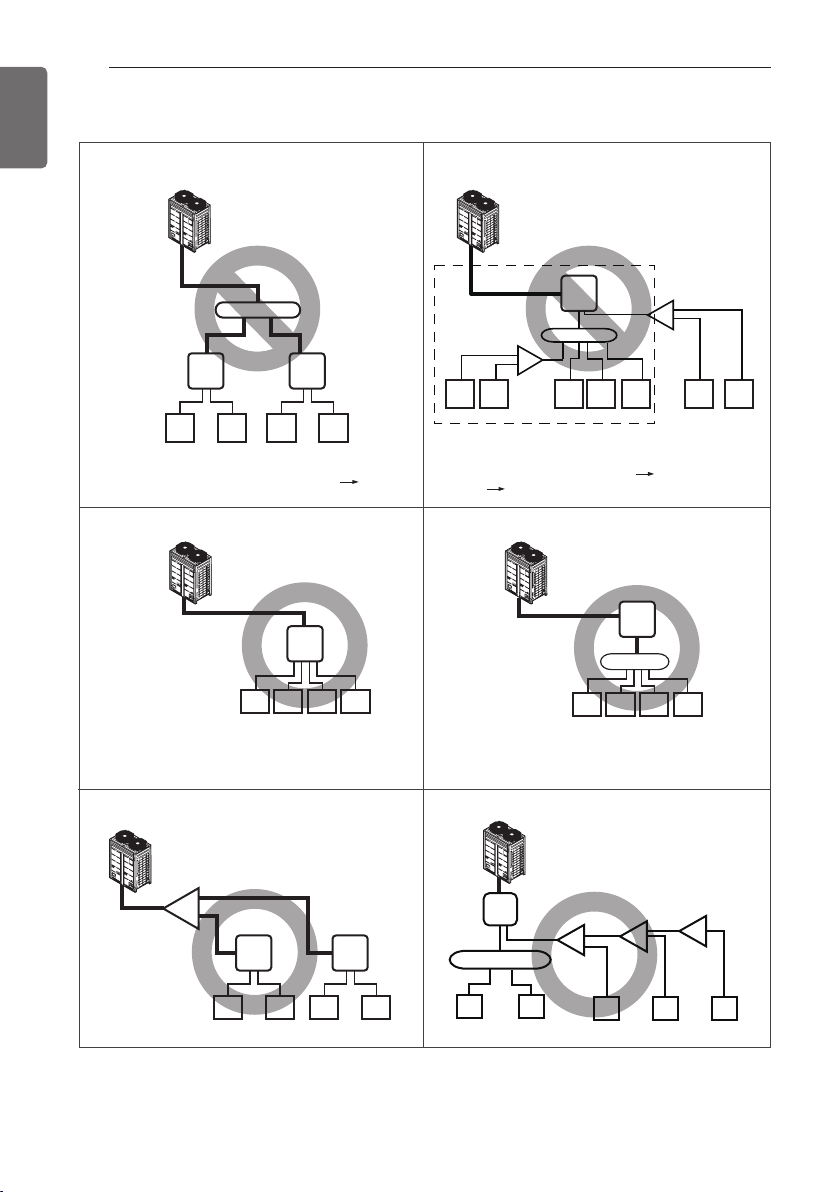
44
PIPE CONNECTIONS BETWEEN INDOOR AND OUTDOOR UNIT
ENGLISH
Y branch, Header and HR unit connection pattern
Pattern 1 Pattern 2
Pattern 3
Pattern 5
HR1
HR1
48k 48k
1
1
2
234567
HR2
48k 48k
7k 7k 7k 7k 7k 24k 24k
3 4
B
HR1
48k 48k 48k 48k
1 2 3 4
Pattern 4
12k 12k 12k 12k
1 2 3 4
HR1
HR1
48k
24k 24k 24k
12k 12k
48k
A
B
1 2
HR2
48k 48k
3 4
Pattern 6
• The maximum total capacity of indoor
units is 58kW(192 kBtu/h).
• The maximum total capacity of a branch
pipe of HR unit is 14.5kW(48 kBtu/h).
• Impossible installation : Head branch pipe HR unit
• Impossible installation : HR unit Head branch
pipe Y and Head branch pipe.
HR1
B
B
A
A
A
A
12 345
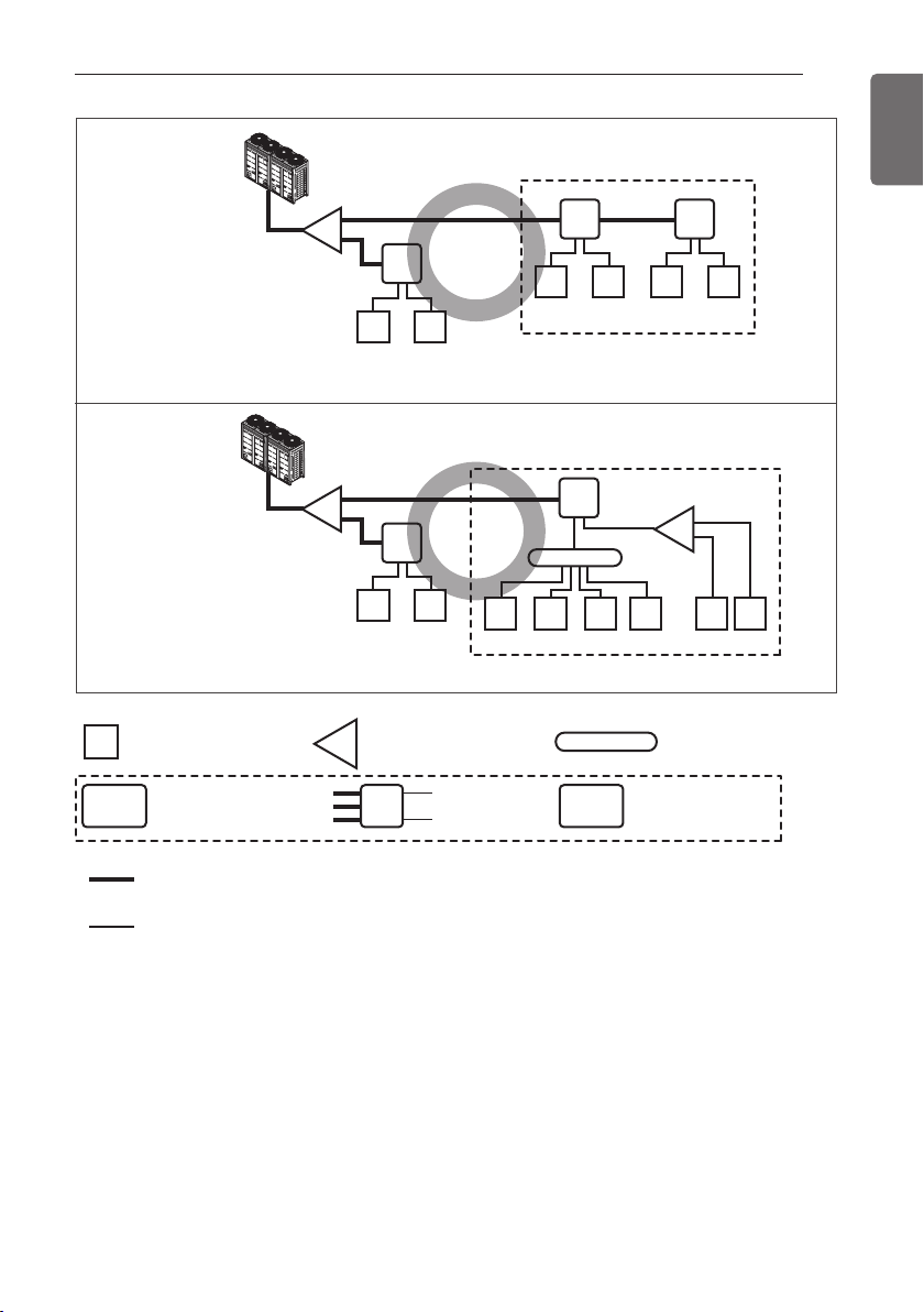
PIPE CONNECTIONS BETWEEN INDOOR AND OUTDOOR UNIT
45
ENGLISH
Pattern 7
Pattern 8
HR1
A
A
A
48k 48k
1 2
• * : Serial connection of HR units : Capacity sum of indoor units ≤ 192 kBtu/h
• * : Maximum indoor units per a branch are 8 indoor units
HR2
48k 48k
3 4
HR3
48k 48k
5 6
*
HR1
48k 48k
1 2
HR2
*
B
12k 12k 12k 12k
3 4 5 6
24k
7
24k
8
• Pipe installation from outdoor units to HR units
: 3 pipes(Low pressure Gas pipe, High pressure Gas pipe, Liquid pipe)
• Pipe installation from HR units to indoor units
: 2
p
i
p
es(Gas
p
i
p
e, Liquid
p
i
p
e)
B
A
1
HR1
Outdoor
Unit
Indoor Unit Y Branch pipe
Low pressure Gas pipe
High pressure Gas pipe
Liquid pipe
Gas pipe
Liquid pipe
Head Branch pipe
Indoor
Unit
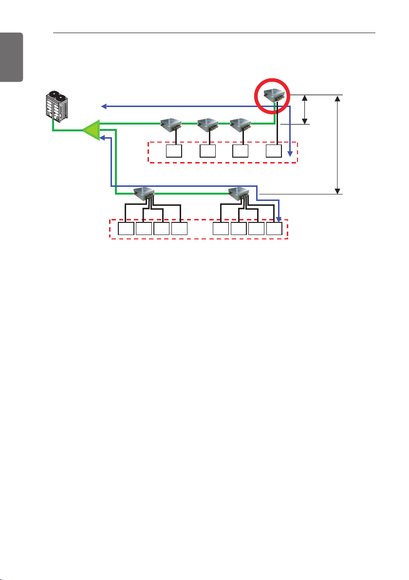
46
PIPE CONNECTIONS BETWEEN INDOOR AND OUTDOOR UNIT
ENGLISH
1) Keep the 40m(131ft) distance from the first branch to the farthest indoor.
1) under 40m(131ft)
Keep the sum of indoor capacity under 58kW(192 kBtu/h).
Indoor
Unit
Indoor
Unit
Indoor
Unit
Indoor
Unit
Indoor
Unit
Indoor
Unit
Indoor
Unit
Indoor
Unit
Indoor
Unit
Indoor
Unit
Indoor
Unit
Indoor
Unit
1) under 40m(131ft)
Y branch
5m(16ft)
15m(49ft)
Keep the sum of indoor capacity under 58kW(192 kBtu/h).
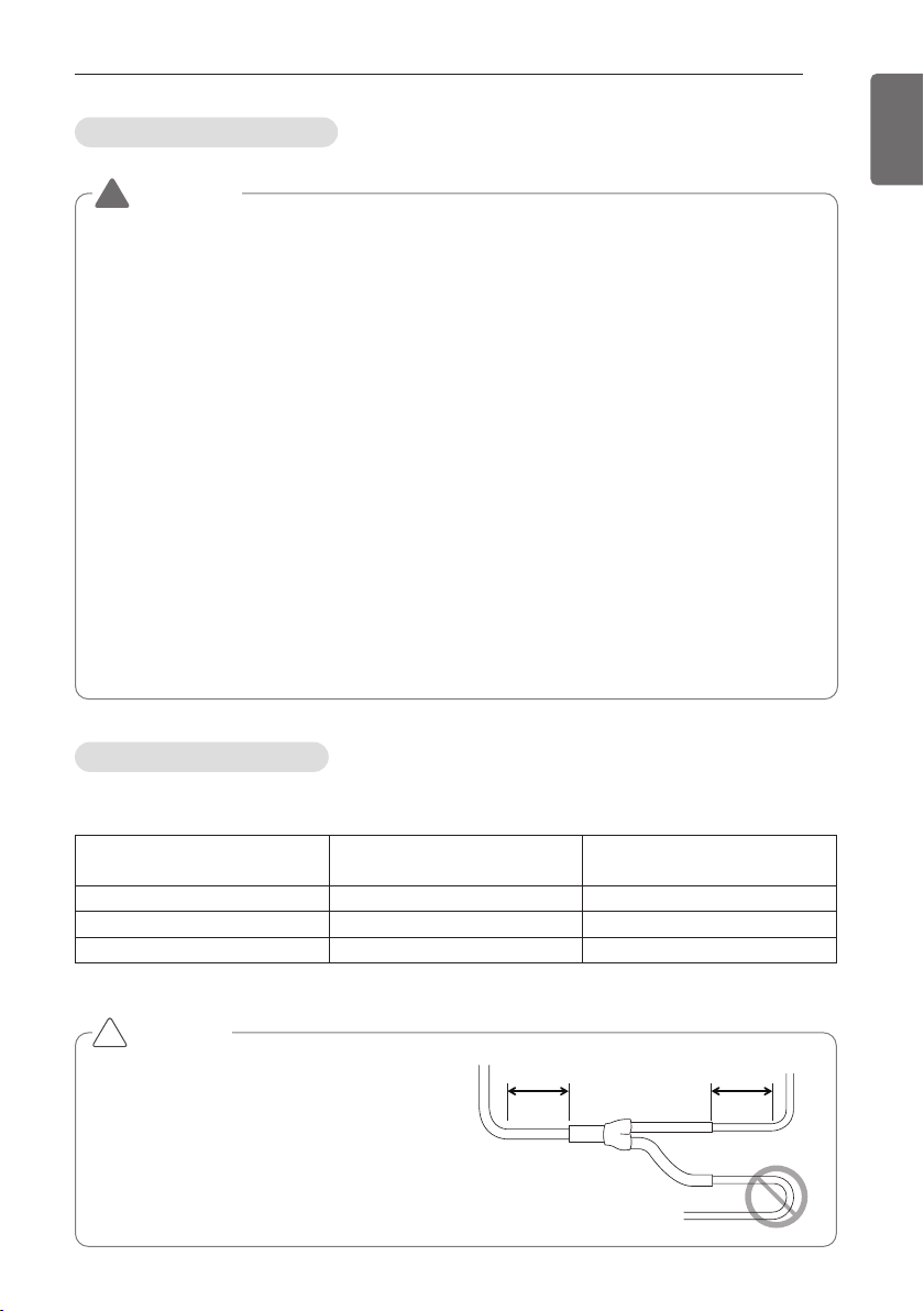
PIPE CONNECTIONS BETWEEN INDOOR AND OUTDOOR UNIT
47
ENGLISH
Outdoor unit Connection
Indoor Unit Connection
Indoor Unit connecting pipe from branch (a,b,c,d,e,f)
Indoor Unit capacity
[kW(Btu/h)]
Liquid pipe [mm(inch)] Gas pipe [mm(inch)]
≤ 5.6(19,100)
Ø6.35(1/4) Ø12.7(1/2)
< 16.0(54,600) Ø9.52(3/8) Ø15.88(5/8)
< 22.4(76,400) Ø9.52(3/8) Ø19.05(3/4)
WARNING
• In case of pipe diameter B connected after first branch is bigger than the main pipe diameter A, B
should be of the same size with A.
Ex) In case indoor unit combination ratio 130% is connected to 20Ton(24HP(70kW)) outdoor unit.
1) Outdoor unit main pipe diameter A : Ø34.9(1-3/8, gas pipe), Ø15.88(5/8, liquid pipe)
2) Pipe diameter B after first branch according to 130% indoor unit combination(91kW): Ø34.9(1-
3/8, gas pipe), Ø19.05(3/4, liquid pipe)
Therefore, pipe diameter B connected after first branch would be Ø34.9(1-3/8, gas pipe) /
Ø15.88(5/8, liquid pipe) which is same with main pipe diameter.
[Example]
nstead of using indoor unit total capacity, use outdoor unit model name in order to choose main pipe di-
ameter by downward.
Do not let the connection pipe from branch to branch exceed the main pipe diameter chosen by outdoor
unit model name.
EX) Where connecting the indoor units to the 20Ton(24HP(70kW))outdoor unit to 130% of its system ca-
pacity (91 kW) and branching 7k Btu/h(2.2kW) indoor unit at the 1st branch
1) Main pipe diameter 20Ton(24 HP) outdoor unit: Ø28.58(1-1/8, Gas pipe) Ø15.88(5/8, Liquid pipe)
Pipe diameter between 1st and 2nd branch (88.5kW indoor units):
Ø34.9(1-3/8, Gas pipe) Ø19.05(3/4, Liquid pipe) in conformity with downward indoor units.
2) Since the main pipe diameter of 20Ton(24 HP) outdoor unit is Ø28.58(1-1/8, Gas pipe) and
Ø15.88(5/8, Liquid pipe), Ø28.58 (1-1/8, Gas pipe) and Ø15.88(5/8, Liquid pipe) is used as the main
pipe and the connection pipe between 1st and 2nd branch.
!
CAUTION
• Bending radius should be at least twice the
diameter of the pipe.
• Bend pipe after 500mm(1.64ft) or more
from branch(or header).
Do not bend U type.
It may cause Performance unsatisfactory or
noise.
!
500mm(1.64ft)
or more
500mm(1.64ft)
or more
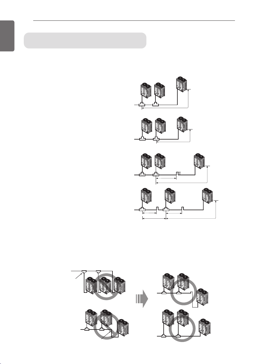
48
PIPE CONNECTIONS BETWEEN INDOOR AND OUTDOOR UNIT
ENGLISH
Pipe Connection Method/Precautions for
Series connections between Outdoor units
- Separate Y branch joints are needed for series connections between outdoor units.
- Please refer to the below connection examples to install pipe connections between outdoor
units.
- If the distance between the outdoor units becomes more than 2m(6.6ft), apply Oil Traps be-
tween the gas pipes.
- If the outdoor unit is located lower than the main pipe, apply Oil Trap.
Pipe connection between outdoor units (General Case)
The maximum pipe length
after the first branching
between the outdoor units is
10m(33ft) or less
Pipes between outdoor units are 2m(6.6ft) or
less
Examples of Wrong Pipe Connections
2m(6.6)ft or less
Pipes between outdoor units are 2m(6.6ft) or
longer
Oil Trap
Oil Trap Oil Trap
2m(6.6ft) or less
2m(6.6ft) or less
2m(6.6ft) or less
0.2m(0.66ft) or more
2m(6.6ft) or longer
2m(6.6ft) or longer2m(6.6ft) or longer
If the main pipe is
higher than the
outdoor units, oil is
accumulated in the
outdoor unit.
If there are differences in the height
between the outdoor units, oil is
accumulated in the lower outdoor unit.
Oil Trap
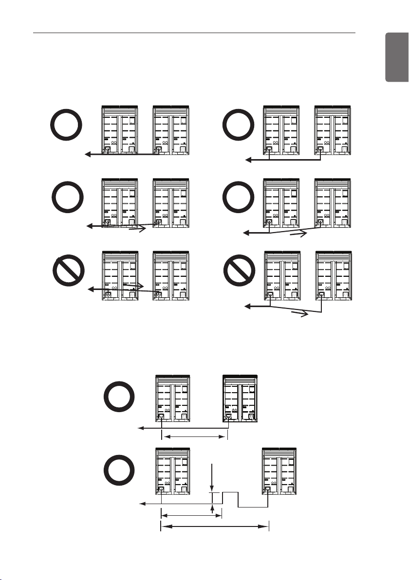
PIPE CONNECTIONS BETWEEN INDOOR AND OUTDOOR UNIT
49
ENGLISH
- The pipes between the outdoor units must maintain horizontal levelness or give an inclination to
prevent a back flow toward the slave outdoor unit. Otherwise, the unit may not operate prop-
erly.
- Apply Oil Trap as shown below when the length of the pipe between the outdoor units is more
than 2m(6.6ft). Otherwise, the unit may not operate properly.
Toward indoor unit
Toward indoor unit
Pipe inclination (2 or more)
Toward indoor unit
Toward indoor unit
Toward indoor unit
Toward indoor unit
(Example 1)
(Example 2)
(Example 3)
(Example 1)
(Example 2)
Toward indoor unit
Toward indoor unit
2m(6.6ft)
2m(6.6ft)
2m(6.6ft)
0.2m(0.66ft)
Oil Trap
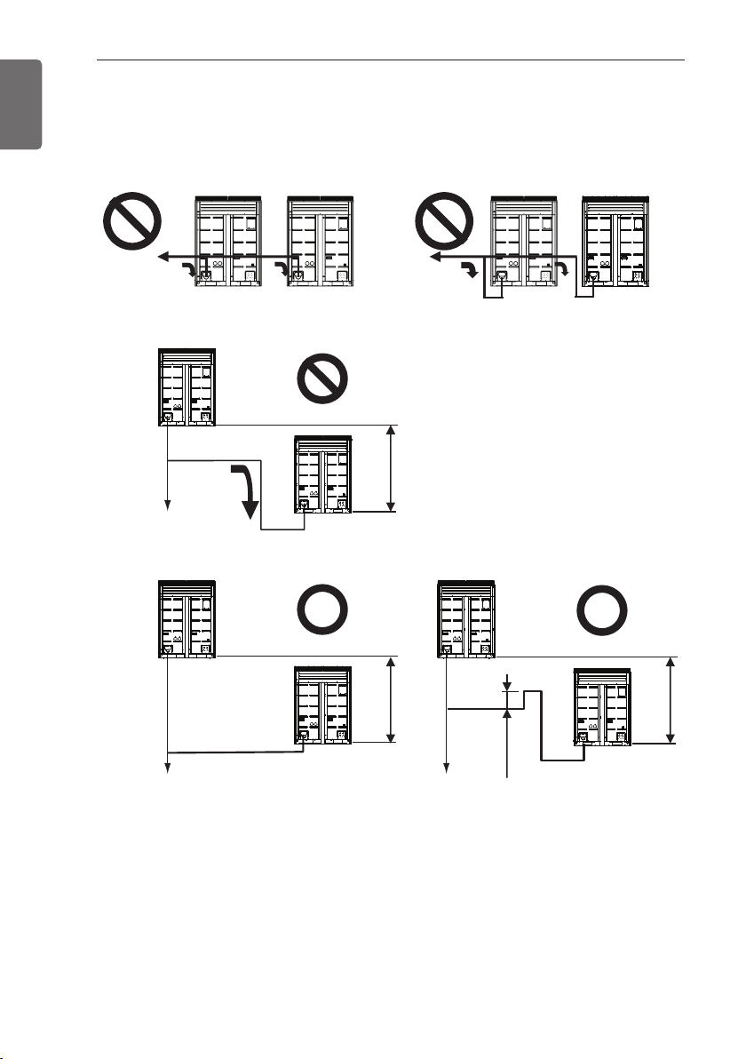
50
PIPE CONNECTIONS BETWEEN INDOOR AND OUTDOOR UNIT
ENGLISH
- When connecting the pipes between the outdoor units, the accumulation of oil in the slave out-
door unit should be avoided. Otherwise, the unit may not operate properly.
(Example 1)
Toward indoor unit
Toward indoor unit
h
h
0.2m(0.66ft)
Toward indoor unit Toward indoor unit
Oil Trap
h
Toward indoor unit
(Example 3)
(Example 2)
* The level difference between two outdoor units, h is allowed up to 5m(16.4ft).
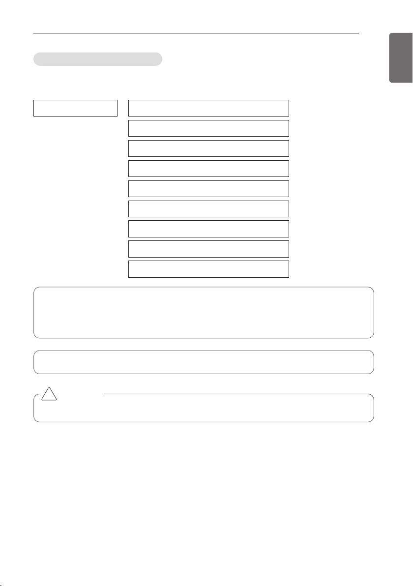
PIPE CONNECTIONS BETWEEN INDOOR AND OUTDOOR UNIT
51
ENGLISH
The amount of Refrigerant
The calculation of the additional charge should take into account the length of pipe and CF(correc-
tion Factor) value of indoor unit.
Additional charge(kg) = Total liquid pipe : Ø25.4 mm (1.0 inch) x 0.480kg/m(0.323(lbs/ft))
+ Total liquid pipe : Ø22.2 mm (7/8 inch) x 0.354kg/m(0.238(lbs/ft))
+ Total liquid pipe : Ø19.05 mm (3/4 inch) x 0.266kg/m(0.179(lbs/ft))
+ Total liquid pipe : Ø15.88 mm (5/8 inch) x 0.173kg/m(0.116(lbs/ft))
+ Total liquid pipe : Ø12.7 mm (1/2 inch) x 0.118kg/m(0.079(lbs/ft))
+ Total liquid pipe : Ø9.52 mm (3/8 inch) x 0.061kg/m(0.041(lbs/ft))
+ Total liquid pipe : Ø6.35 mm (1/4 inch) x 0.022kg/m(0.015(lbs/ft))
+ Number of installed HR unit x 5kg(1.1lbs)
+ CF value of indoor unit
Amount refrigerant of Indoor units
Example) 4Way Ceiling Cassette 14.5kW -1ea, Ceiling concealed Duct 7.3kW-2ea,
Wall Mounted 2.3kW-4ea
CF = 0.64 × 1 + 0.26 × 2 + 0.24 × 4 = 2.12kg (4.67lbs)
Attach the additional refrigerant table of IDU.
CAUTION
Use only 2-series of indoor unit. Ex) ARNU***2/A
!
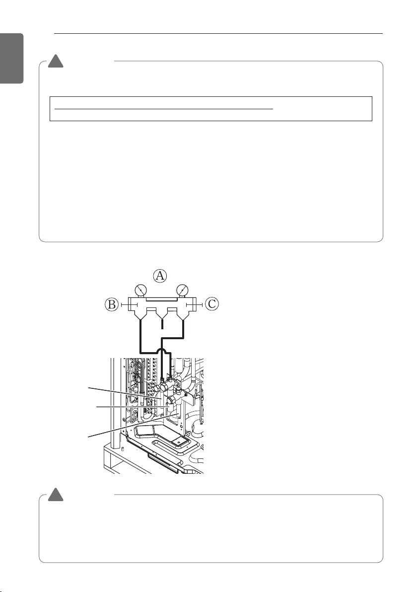
52
PIPE CONNECTIONS BETWEEN INDOOR AND OUTDOOR UNIT
ENGLISH
WARNING
• Regulation for refrigerant leakage
: the amount of refrigerant leakage should satisfy the following equation for human safety.
If the above equation can not be satisfied, then follow the following steps.
• Selection of air conditioning system: select one of the next
- Installation of effective opening part
- Reconfirmation of Outdoor Unit capacity and piping length
- Reduction of the amount of refrigerant
- Installation of 2 or more security device (alarm for gas leakage)
• Change Indoor Unit type
:
installation position should be over 2m(6.56ft) from the floor (Wall mounted type ’ Cassette type)
• Adoption of ventilation system
: choose ordinary ventilation system or building ventilation system
• Limitation in piping work
: Prepare for earthquake and thermal stress
Liquid pipe
Low Pressure
Gas pipe
High Pressure
Gas pipe
Ⓐ Manifold Gauge
Ⓑ Low pressure side Handle
Ⓒ High pressure side Handle
Total amount of refrigerant in the system
≤ 0.44(kg/m
3
(0.028(lbs/ft
3
))
Volume of the room at which Indoor Unit of the least capacity is installed
!
WARNING
• Pipe to be vacuumed : gas pipe, liquid pipe
• If the refrigerant amount is not exact, it may not operate properly.
• If additionally bottled refrigerant amount is over 10%, condenser burst or insufficient indoor
unit performance may be caused.
• The total amount of refrigerant can be added up to 15%.
!
Refrigerant charging
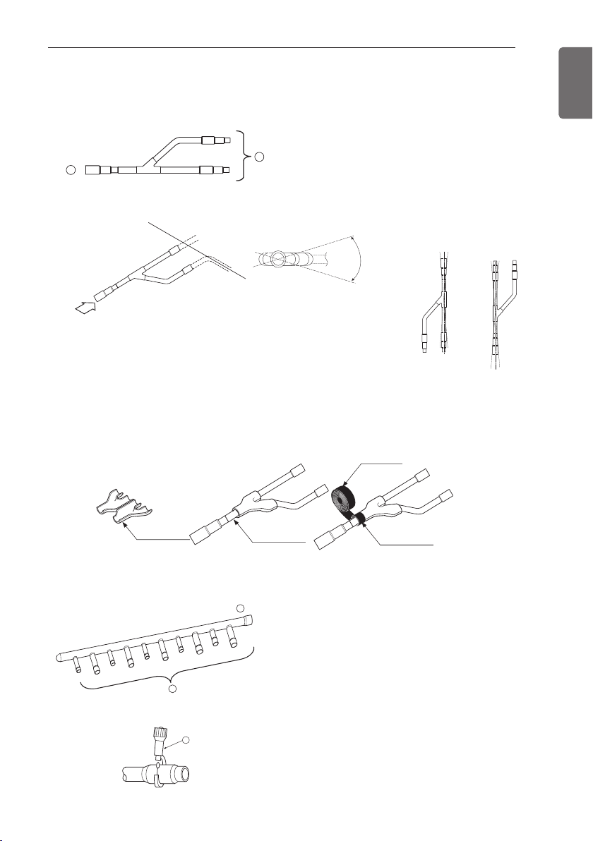
PIPE CONNECTIONS BETWEEN INDOOR AND OUTDOOR UNIT
53
ENGLISH
Y branch
Header
A
B
Facing
upwards
Facing
downwards
Within ±3° Within ±3°
Viewed from point A
in direction of arrow
Horizontal
plane
A
Within +/- 10°
Insulator
(included with kit)
Liquid and gas
pipe joints
Insulator for
field piping
Tape
(field supply)
A
B
C
Ⓐ To Branch Piping or Indoor Unit
Ⓑ To Outdoor Unit
• Ensure that the branch pipes are attached horizontally or vertically (see the diagram below.)
• There is no limitation on the joint mounting configuration.
• If the diameter of the refrigerant piping selected by the procedures described is different from
the size of the joint, the connecting section should be cut with a pipe cutter.
• Branch pipe should be insulated with the insulator in each kit.
Ⓐ To Outdoor Unit Ⓑ To Indoor Unit
• The indoor unit having larger capacity must be in-
stalled closer to Ⓐ than smaller one.
• If the diameter of the refrigerant piping selected
by the procedures described is different from the
size of the joint, the connecting section should
be cut with a pipe cutter.
ⓒ Pipe cutter
• When the number of pipes to be connected
is smaller than the number of header
branches, install a cap to the unconnected
branches.
Branch pipe Fitting
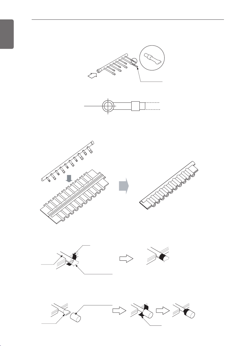
54
PIPE CONNECTIONS BETWEEN INDOOR AND OUTDOOR UNIT
ENGLISH
• When the number of indoor units to be connected to the branch pipes is less than the number
of branch pipes available for connection then cap pipes should be fitted to the surplus branches.
• Fit branch pipe lie in a horizontal plane.
• Header should be insulated with the insulator in each kit.
• Joints between branch and pipe should be sealed with the tape included in each kit.
• Any cap pipe should be insulated using the insulator provided with each kit and then taped as
described above.
Pinched pipe
B
Horizontal plane
View from point B in the direction of the arrow
Insulate the header using
the insulation
material attached to the
branch pipe kit
as shown in the figure.
Insulator
Insulator of field pipe
Tape
Tape
Cap pipe
Insulator for cap pipe
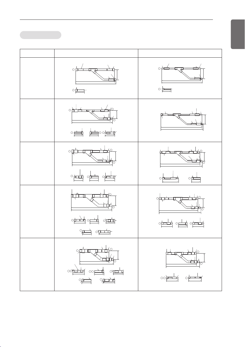
PIPE CONNECTIONS BETWEEN INDOOR AND OUTDOOR UNIT
55
ENGLISH
Y branch pipe
Models Gas pipe Liquid pipe
ARBLN01621
I.D19.05(3/4)
O.D15.88(5/8)
I.D12.7(1/2)
I.D15.88(5/8)
I.D15.88(5/8)
I.D15.88(5/8)
I.D12.7(1/2)
I.D12.7(1/2)
292(11-1/2)
281(11-1/16)
74
(2-29/32)
70(2-3/4)
1
1
I.D12.7(1/2)
292(11-1/2)
281(11-1/16)
74
(2-29/32)
70(2-3/4)
I.D6.35(1/4)
I.D6.35(1/4)
I.D6.35(1/4)
1
1
I.D9.52(3/8)
I.D9.52(3/8)
I.D9.52(3/8)
O.D9.52(3/8)
ARBLN03321
413(16-1/4)
390(15-11/32)
I.D19.05(3/4)
I.D19.05(3/4)
I.D19.05(3/4)
I.D12.7(1/2)
I.D12.7
(1/2)
70(2-3/4)
I.D15.88(5/8)
I.D15.88(5/8)
I.D25.4(1)
I.D25.4(1)
O.D25.4(1)
80(3-5/32)
110(4-11/32)
83
(3-9/32)
1
2
3
3
O.D19.05(3/4)
O.D19.05(3/4)
1 2
I.D22.2(7/8)
I.D22.2(7/8)
I.D22.2(7/8)
I.D28.58(1-1/8)
I.D12.7(1/2)
I.D12.7(1/2)
I.D12.7(1/2)
74
(2-29/32)
332(13-1/16)
321(12-5/8)
I.D6.35(1/4)
I.D6.35(1/4)
I.D9.52(3/8)
I.D9.52(3/8)
I.D9.52(3/8)
ARBLN07121
I.D12.7
(1/2)
376(14-13/16)
404(15-29/32)
120(4-23/32) 120(4-23/32)
90(3-17/32)
I.D15.88(5/8)
I.D15.88(5/8)
2
3
1
2
1 3
I.D19.05(3/4)
I.D19.05(3/4)
O.D19.05(3/4)
96
(3-25/32)
I.D22.2(7/8)
I.D22.2(7/8)
O.D22.2(7/8)
I.D34.9(1-3/8)
I.D28.58(1-1/8)
I.D28.58(1-1/8)
I.D28.58(1-1/8)
O.D31.8(1-1/4)
I.D31.8(1-1/4)
I.D31.8(1-1/4)
I.D15.88(5/8)
I.D15.88(5/8)
I.D15.88(5/8)
I.D12.7(1/2)
I.D12.7(1/2)
I.D12.7(1/2)
O.D12.7(1/2)
O.D12.7(1/2)
70(2-3/4)
110(4-11/32)
371(14-19/32)
394(15-1/2)
83
(3-9/32)
2
3
3
I.D19.05(3/4)
I.D19.05(3/4)
I.D19.05(3/4)
2
I.D6.35(1/4)
I.D9.52(3/8)
I.D9.52(3/8)
ARBLN14521
I.D12.7(1/2)
70(2-3/4)
471(18-17/32)
517(20-11/32)
125
(4-29/32)
130(5-1/8)
I.D15.88(5/8)
I.D41.3(1-5/8)
I.D41.3
(1-5/8)
I.D41.3(1-5/8)
I.D38.1(1-1/2)
I.D38.1(1-1/2)
I.D38.1(1-1/2)
O.D38.1(1-1/2)
O.D15.88(5/8)
2
3
3
2
2
3
3
120(4-23/32)
120(4-23/32)
90(3-17/32)
I.D19.05(3/4)
I.D19.05(3/4)
I.D22.2(7/8)
I.D22.2(7/8)
O.D22.2(7/8)
I.D34.9(1-3/8)
I.D34.9(1-3/8)
I.D34.9(1-3/8)
O.D34.9(1-3/8)
I.D28.58(1-1/8)
O.D28.58(1-1/8)
I.D28.58(1-1/8)
I.D12.7(1/2)
O.D12.7(1/2)
I.D12.7
(1/2)
110(4-11/32)110(4-11/32)
41616-3/8)
444(17-15/32)
O.D15.88(5/8)
I.D15.88(5/8)
I.D19.05(3/4)
I.D15.88(5/8)
I.D15.88(5/8)
I.D19.05(3/4)
I.D19.05(3/4)
O.D19.05(3/4)
80(3-5/32)
2
3
1
2 3 3
96
(3-25/32)
I.D22.2(7/8)
I.D22.2(7/8)
I.D22.2(7/8)
I.D6.35(1/4)
I.D9.52(3/8)
I.D9.52(3/8)
ARBLN23220
O.D.
28.58(1-1/8)
I.D.
22.2(7/8)
115(4-17/32)
X2
100(4-11/32)
O.D15.88(5/8)
I.D12.7(1/2)
70(2-3/4)
O.D.
22.2(7/8)
I.D.
15.88(5/8)
I.D.
19.05(3/4)
120(4-23/32)
O.D.38.1(1-1/2)
I.D.34.9(1-3/8)
I.D.28.58(1-1/8)
O.D.44.48(1-3/4)
X2
175(6-7/8)
I.D31.8(1-1/4)
I.D.53.98(2-1/4t I.D.
25.4(1)
I.D.44.48(1-3/4)
I.D.44.48(1-3/4)
I.D38.1(1-1/2)I.D41.3(1-5/8)
I.D.44.48(1-3/4)
I.D38.1(1-1/2)
I.D41.3(1-5/8)
I.D.53.98(2-1/4)
420(16-17/32)
490(19-9/32)
134
1
2
3
32
3 3
3
3
2
O.D.
19.05(3/4)
O.12.7(1/2)
I.D.15.88(5/8)
O.12.7(1/2) .D6.35(1/4)
I.D9.52(3/8)
X2
110(4-11/32) 110(4-11/32)
I.D25.4(1) I.D.
22.2(7/8)
I.D.
19.05(3/4)
I.D.
19.05(3/4)
I.D.
22.2(7/8)
I.D.
25.4(1)
I.D.
25.4(1)
I.D.
22.2(7/8)
346(13-5/8)
379(14-29/32)
96(3-25/32)
2
3 32
3
[Unit:mm(inch)]
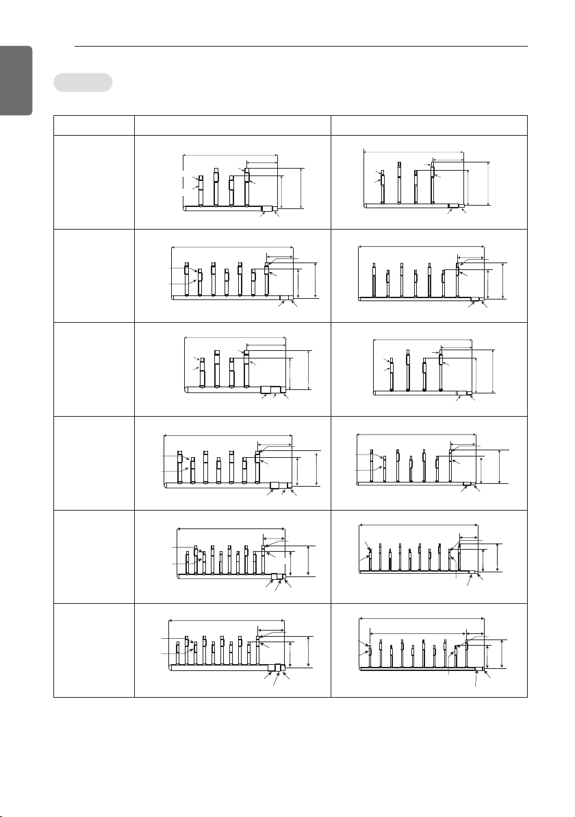
56
PIPE CONNECTIONS BETWEEN INDOOR AND OUTDOOR UNIT
ENGLISH
Header
Models Gas pipe Liquid pipe
4 branch
ARBL054
360(14-5/32)
120(4-23/32)
ID15.88(5/8)
ID12.7(1/2)
ID12.7(1/2)
ID15.88(5/8)
ID15.88(5/8)
ID19.05(3/4)
150
(5-29/32)
ID15.88(5/8)
ID12.7(1/2)
120
(4-23/32)
ID15.88(5/8)
ID12.7(1/2)
ID9.52(3/8)
ID6.35(1/4)
ID9.52(3/8)
ID6.35(1/4)
120(4-23/32)
360(14-5/32)
ID9.52(3/8)
ID9.52(3/8)
ID6.35(1/4)
ID6.35(1/4)
ID9.52(3/8)
ID12.7(1/2)
150
(5-29/32)
ID15.88(5/8)
ID12.7(1/2)
120
(4-23/32)
ID15.88(5/8)
ID12.7(1/2)
ID9.52(3/8)
ID6.35(1/4)
ID9.52(3/8)
ID6.35(1/4)
7 branch
ARBL057
540(21-1/4)
150
(5-29/32
ID15.88(5/8)
ID12.7(1/2)
120
(4-23/32)
120(4-23/32)
ID15.88(5/8)
ID12.7(1/2)
ID15.88(5/8)
ID12.7(1/2)
ID15.88(5/8)
ID19.05(3/4)
ID15.88(5/8)
ID12.7(1/2)
ID9.52(3/8)
ID6.35(1/4)
ID9.52(3/8)
ID6.35(1/4)
540(21-1/4)
32)
150
(5-29/32)
ID15.88(5/8)
ID12.7(1/2)
120
(4-23/32)
120(4-23/32)
ID6.35(1/4)
ID9.52(3/8)
ID9.52(3/8)
ID12.7(1/2)
ID15.88(5/8)
ID12.7(1/2)
ID9.52(3/8)
ID6.35(1/4)
ID9.52(3/8)
ID6.35(1/4)
4 branch
ARBL104
150
(5-29/32)
400(15-23/32)
160(6-5/16)
ID15.88(5/8)ID15.88(5/8)
ID12.7(1/2)ID12.7(1/2)
ID15.88(5/8)
ID12.7(1/2)
ID19.05(3/4)
ID15.88(5/8)
ID22.2(7/8)
ID28.58(1-1/8)
ID25.4(1)
120
(4-23/32)
ID15.88(5/8)
ID12.7(1/2)
ID9.52(3/8)
ID6.35(1/4)
ID9.52(3/8)
ID6.35(1/4)
ID15.88(5/8)
ID12.7(1/2)
ID15.88(5/8)
ID12.7(1/2)
ID9.52(3/8)
ID6.35(1/4)
ID9.52(3/8)
ID6.35(1/4)
150
(5-29/32)
120(4-23/32)
120
(4-23/32)
360(14-5/32)
ID9.52(3/8)
ID9.52(3/8)
ID6.35(1/4)
ID6.35(1/4)
ID9.52(3/8)
ID12.7(1/2)
7 branch
ARBL107
ID15.88(5/8)
ID12.7(1/2)
120
(4-23/32)
160(6-5/16)
580(22-27/32)
ID19.05(3/4)
ID15.88(5/8)
ID15.88(5/8)ID15.88(5/8)
ID12.7(1/2)ID12.7(1/2)
ID15.88(5/8)
ID12.7(1/2)
ID22.2(7/8)
ID28.58(1-1/8)
ID25.4(1)
ID9.52(3/8)
ID6.35(1/4)
ID9.52(3/8)
ID6.35(1/4)
150
(5-29/3
ID15.88(5/8)
ID12.7(1/2)
120
(4-23/32)
ID15.88(5/8)
ID12.7(1/2)
700(27-9/16)
120(4-23/32)
ID6.35(1/4)
ID9.52(3/8)
ID9.52(3/8)ID9.52(3/8)
ID6.35(1/4)ID6.35(1/4)
ID9.52(3/8)
ID6.35(1/4)
ID9.52(3/8)ID12.7(1/2)
ID9.52(3/8)
ID6.35(1/4)
150
(5-29/32)
32)
10 branch
ARBL1010
ID15.88(5/8)
ID12.7(1/2)
ID15.88(5/8)
ID12.7(1/2)
ID9.52(3/8)
ID6.35(1/4)
ID15.88(5/8)
ID12.7(1/2)
ID9.52(3/8)
ID6.35(1/4)
120
(4-23/32)
160(6-5/16)
760(29-28/32)
ID19.05(3/4)
ID15.88(5/8)
ID22.2(7/8)
ID28.58(1-1/8)
ID25.4(1)
150
(5-29/32)
ID15.88(5/8)
ID12.7(1/2)
120
(4-23/32)
ID15.88(5/8)
ID12.7(1/2)
ID9.52(3/8)
ID6.35(1/4)
120(4-23/32)
720(28-11/32)
ID6.35(1/4)
ID9.52(3/8)
ID9.52(3/8)
ID6.35(1/4)
ID12.7(1/2)
ID9.52(3/8)
ID9.52(3/8)
ID6.35(1/4)
150
(5-29/32)
10 branch
ARBL2010
ID15.88(5/8)
ID12.7(1/2)
ID15.88(5/8)
ID12.7(1/2)
ID9.52(3/8)
ID6.35(1/4)
ID9.52(3/8)
ID6.35(1/4)
120
(4-23/32)
182(7-5/32)
775(30-17/32)
ID19.05(3/4)
ID15.88(5/8)
ID15.88(5/8)
ID12.7(1/2)
ID28.58(1-1/8)
ID31.8(1-1/4)
ID34.9(1-3/8)
150
(5-29/32)
ID15.88(5/8)
ID12.7(1/2)
120
(4-23/32)
ID15.88(5/8)
ID12.7(1/2)
ID9.52(3/8)
ID6.35(1/4)
107(4-7/32)
60*9=540(21-1/2)
700(27-9/16)
ID6.35(1/4)
ID9.52(3/8)
ID19.05(3/4)
ID15.88(5/8)
ID9.52(3/8)
ID6.35(1/4)
ID9.52(3/8)
ID6.35(1/4)
150
(5-29/32)
[Unit:mm(inch)]
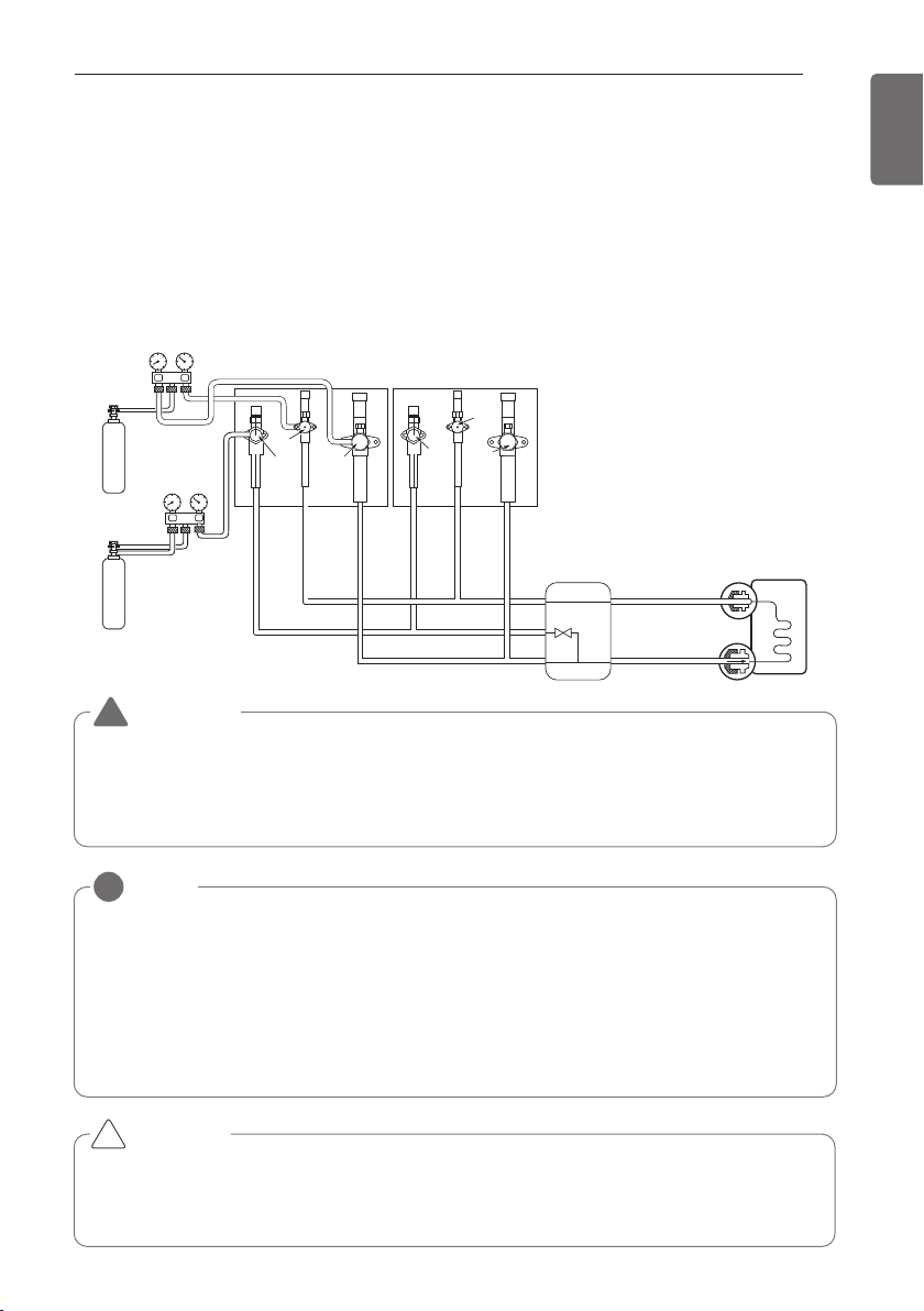
PIPE CONNECTIONS BETWEEN INDOOR AND OUTDOOR UNIT
57
ENGLISH
Leak test
Leak test should be made by pressurizing nitrogen gas to 3.8 MPa(551.1psi). If the pressure does
not drop for 24 hours, the system passes the test. If the pressure drops, check where the nitro-
gen leaks. For the test method, refer to the following figure. (Make a test with the service valves
closed. Be also sure to pressurize liquid pipe, gas pipe and high/low pressure common pipe)
The test result can be judged good if the pressure has not be reduced after leaving for about one
day after completion of nitrogen gas pressurization.
Indoor unit
Nitrogen gas
cylinder
Nitrogen gas
cylinder
Slave 1 outdoor unit Master outdoor unit
High Pressure
Gas pipe
High Pressure
Gas pipe
Liquide pipe
Liquide pipe
Low Pressure
Gas pipe
Low Pressure
Gas pipe
Liquid side
Gas side
Close
Close
Close
Close
Close
Close
HR unit
NOTE
!
If the ambient temperature differs between the time when pressure is applied and when the pressure drop is
checked, apply the following correction factor
There is a pressure change of approximately 0.01Mpa(1.5psi) for each 33.8°F of temperature difference.
Correction= (Temp. at the time of pressurization – Temp. at the time of check) X 0.1
For example: Temperature at the time of pressurization 3.8MPa(551psi) is 80.6°F
24 hour later: 3.73MPa(541psi), 68°F
In this case the pressure drop of 0.07MPa(10psi) is because of temperature drop
And hence there is no leakage in pipe occurred.
CAUTION
To prevent the nitrogen from entering the refrigeration system in the liquid state, the top of
the cylinder must be at higher position than the bottom when you pressurize the system.
Usually the cylinder is used in a vertical standing position.
!
WARNING
Use a vacuum pump or Inert(nitrogen) gas when doing leakage test or air purge. Do not com-
press air or Oxygen and do not use Flammable gases. Otherwise, it may cause fire or explo-
sion.
- There is the risk of death, injury, fire or explosion.
!
Leak Test and Vacuum drying
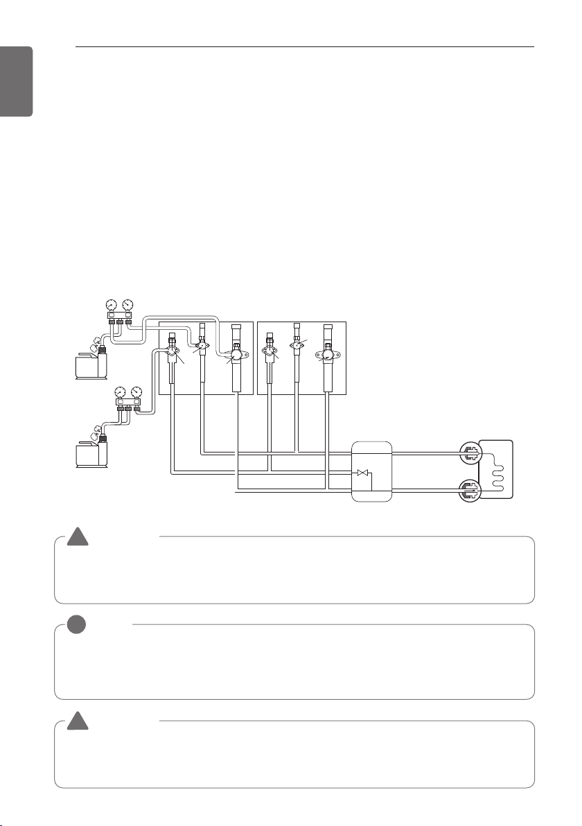
58
PIPE CONNECTIONS BETWEEN INDOOR AND OUTDOOR UNIT
ENGLISH
Vacuum
Vacuum drying should be made from the service port provided on the outdoor unit’s service valve to the vacuum
pump commonly used for liquid pipe, gas pipe and high/low pressure common pipe. (Make Vacuum from liquid
pipe, gas pipe and high/low pressure common pipe with the service valve closed.)
* Never perform air purging using refrigerant.
• Vacuum drying: Use a vacuum pump that can evacuate to -100.7kPa (-14.6psi, 5 Torr, -755mmHg).
- Evacuate the system from the liquid and gas pipes with a vacuum pump for over 2 hrs and bring the
system to -100.7kPa(-14.6psi). After maintaining system under that condition for over 1 hr, confirm
the vacuum gauge rises. The system may contain moisture or leak.
- Following should be executed if there is a possibility of moisture remaining inside the pipe.
(Rainwater may enter the pipe during work in the rainy season or over a long period of time)
After evacuating the system for 2 hrs, give pressure to the system to 0.05MPa(7.3psi) (vacuum
break) with nitrogen gas and then evacuate it again with the vacuum pump for 1hr to -100.7kPa(-
14.6psi)(vacuum drying). If the system cannot be evacuated to -100.7kPa(-14.6psi) within 2 hrs, re-
peat the steps of vacuum break and its drying. Finally, check if the vacuum gauge does not rise or
not, after maintaining the system in vacuum for 1 hr.
Scale
Use a graviometer. (One that can measure
down to 0.1kg(0.22lbs)). If you are unable
to prepare such a high-precision
gravimeter you may use a charge cylinder.
Indoor unit
Slave 1 outdoor unit Master outdoor unit
Liquide pipe
High Pressure
Gas pipe
High Pressure
Gas pipe
Liquide pipe
Low Pressure
Gas pipe
Low Pressure
Gas pipe
Liquid side
Gas side
Close
Close
Close
Close
Close
Close
Vacuum
pump
Vacuum
pump
HR unit
NOTE
!
Always add an appropriate amount of refrigerant. (For the refrigerant additional charge)
Too much or too little refrigerant will cause trouble.
To use the Vacuum Mode
(If the Vacuum mode is set, all valves of Indoor units and Outdoor units will be opened.)
WARNING
Use a vacuum pump or Inert(nitrogen) gas when doing leakage test or air purge. Do not compress
air or Oxygen and do not use Flammable gases. Otherwise, it may cause fire or explosion.
- There is the risk of death, injury, fire or explosion.
!
WARNING
When installing and moving the air conditioner to another site, recharge after perfect evacuation.
- If a different refrigerant or air is mixed with the original refrigerant, the refrigerant cycle may
malfunction and the unit may be damaged.
!
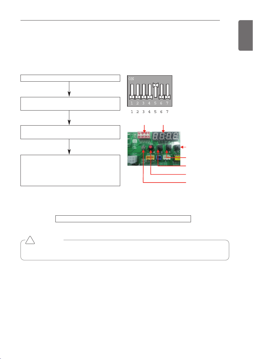
PIPE CONNECTIONS BETWEEN INDOOR AND OUTDOOR UNIT
59
ENGLISH
This function is used for creating vacuum in the system after compressor replacement, ODU
parts replacement or IDU addition/replacement.
Vacuum mode setting method
Vacuum mode off method
CAUTION
ODU operation stops during vacuum mode. Compressor can't operate.
Master unit PCB DIP switch on : No.5
Select the mode using ‘▶’, ‘◀’ Button :
“SVC” Push the ‘●’ button
Select the Function using ‘▶’, ‘◀’ Button : :
“Se3” Push the ‘●’ button
Start the vacuum mode : “VACC”
ODU V/V open
ODU EEV open
IDU EEV open
Dip switch off and push the reset button on Master unit PCB
!
Vacuum Mode
DIP SWITCH 7-Segment
SW01C ( : confirm)
SW02C ( : backward)
: forward)
SW04C
( X : cancel)
SW01D (reset)
SW03C (
ȭ
ȯ
Ɨ
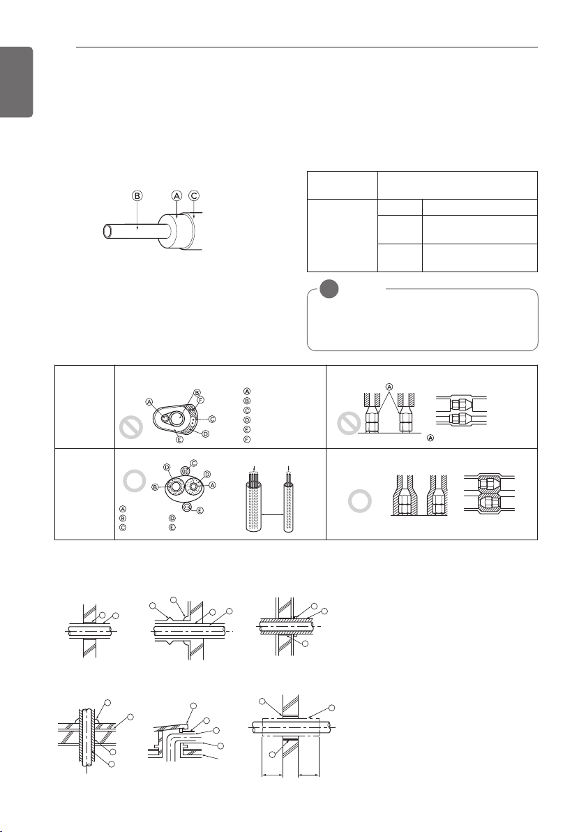
60
PIPE CONNECTIONS BETWEEN INDOOR AND OUTDOOR UNIT
ENGLISH
Be sure to give insulation work to refrigerant piping by covering liquid pipe and gas pipe sepa-
rately with enough thickness heat-resistant polyethylene, so that no gap is observed in the joint
between indoor unit and insulating material, and insulating materials themselves. When insula-
tion work is insufficient, there is a possibility of condensation drip, etc. Pay special attention to in-
sulation work to ceiling plenum.
Ⓐ Heat insulation material
Ⓑ Pipe
Ⓒ Outer covering(Wind the connection part
and cutting part of heat insulation material
with a finishing tape.)
Penetrations
Heat insulation
material
Adhesive + Heat - resistant poly-
ethylene foam + Adhesive tape
Outer
covering
Indoor Vinyl tape
Floor ex-
posed
Water-proof hemp cloth +
Bronze asphalt
Outdoor
Water-proof hemp cloth +
Zinc plate + Oily paint
NOTE
!
When using polyethylene cover as cover-
ing material, asphalt roofing shall not be
required.
Bad
example
• Do not insulate gas or low pressure pipe and liquid or high
pressurepipe together.
Liquid pipe
Gas pipe
Power cables
Finishing tape
Insulating material
Communication cables
• Be sure to fully insulate connecting portion.
These parts are not insulated.
Good
example
Liquid pipe
Communication cables
Communication cables
Separ
-ation
Gas pipe
Power cables
Insulating material
Power cables
Ⓐ Sleeve
Ⓑ Heat insulating material
Ⓒ Lagging
Ⓓ Caulking material
Ⓔ Band
Ⓕ Waterproofing layer
Ⓖ Sleeve with edge
Ⓗ Lagging material
Ⓘ Mortar or other incombustible caulking
Ⓙ Incombustible heat insulation material
When filling a gap with mortar, cover the
penetration part with steel plate so that
the insulation material will not be caved
in. For this part, use incombustible mate-
rials for both insulation and covering.
(Vinyl covering should not be used.)
1m
(3.28ft)
1m
(3.28ft)
A
B
D
F
G
B
G
D
B
H
I
J
A
E
B
I
A
B
D
C
Inner wall (concealed)
Floor (fireproofing)
Penetrating portion on fire
limit and boundary wall
Roof pipe shaft
Outer wall Outer wall (exposed)
Thermal insulation of refrigerant piping
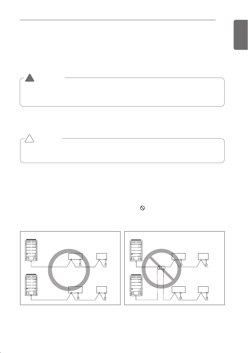
ELECTRICAL WIRING
61
ENGLISH
Caution
- Follow ordinance of your governmental organization for technical standard related to electrical
equipment, wiring regulations and guidance of each electric power company.
-
Install the Outdoor Unit communication cable away from the power source wiring so that it is not af-
fected by electric noise from the power source. (Do not run it through the same conduit.)
- Be sure to provide designated grounding work to Outdoor Unit.
- Give some allowance to wiring for electrical part box of Indoor and Outdoor Units, because the
box is sometimes removed at the time of service work.
- Never connect the main power source to terminal block of communication cable. If connected,
electrical parts will be burnt out.
- Use 2-core shield cable for communication cable.(O mark in the figure below) If communication
cable of different systems are wired with the same multiplecore cable, the resultant poor trans-
mitting and receiving will cause erroneous operations. ( mark in the figure below)
- Only the communication cable specified should be connected to the terminal block for Outdoor
Unit communication.
CAUTION
Be sure to correct the outdoor unit to earth. Do not connect ground wire to any gas pipe, liquid
pipe, lightening rod or telephone earth line. If earth is incomplete, it may cause an electric shock.
2-Core Shield Cable Multi-Core Cable
Remote
control
Remote
control
Remote
control
Remote
control
Indoor
Unit
Outdoor Unit
Outdoor Unit
Indoor
Unit
Indoor
Unit
Indoor
Unit
Outdoor Unit
Outdoor Unit
Remote
control
Remote
control
Indoor
Unit
Indoor
Unit
Remote
control
Remote
control
Indoor
Unit
Indoor
Unit
!
WARNING
Be sure to have authorized electrical engineers do the electric work using special circuits in
accordance with regulations and this installation manual. If power supply circuit has a lack of
capacity or electric work deficiency, it may cause an electric shock or fire.
!
ELECTRICAL WIRING
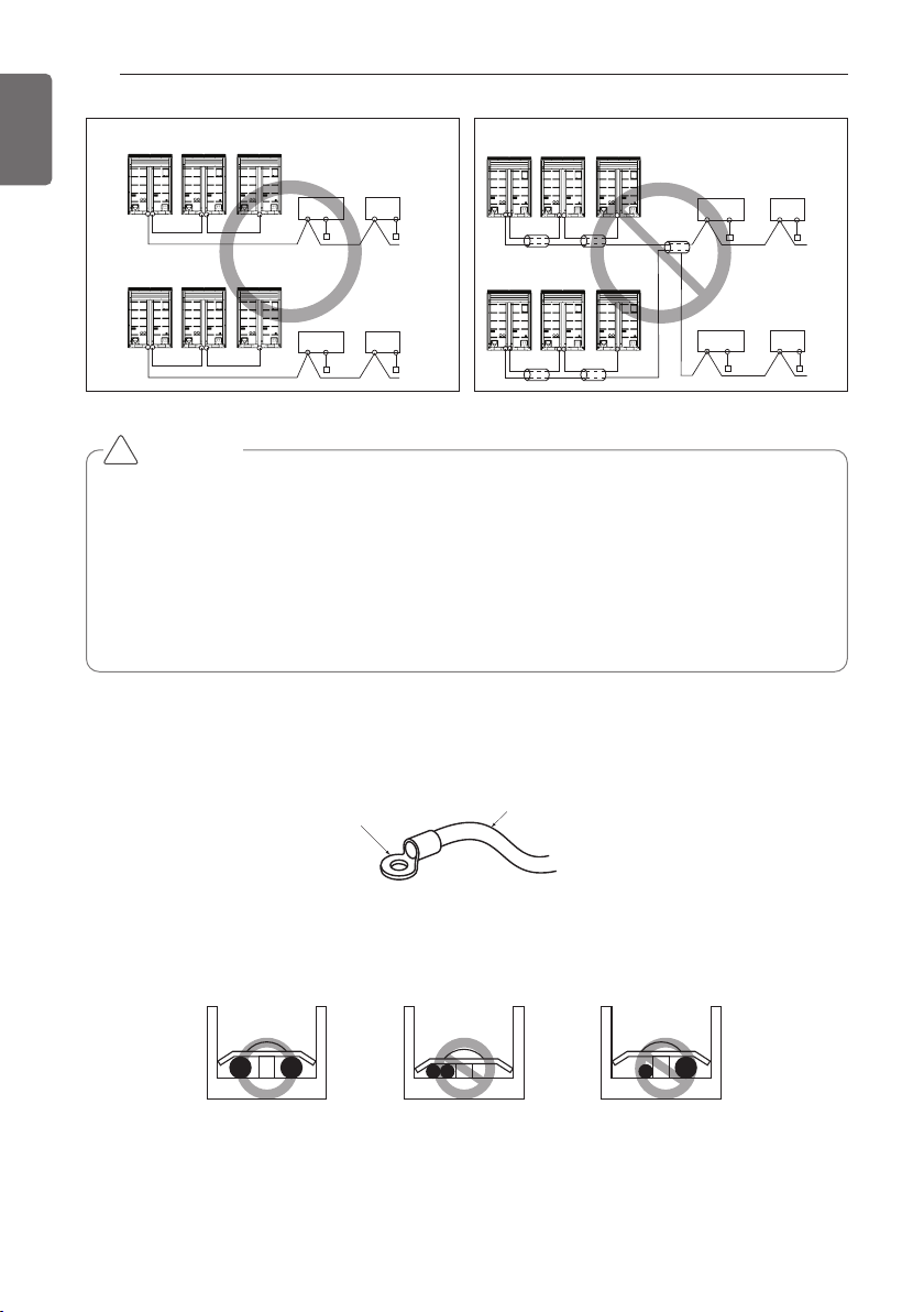
62
ELECTRICAL WIRING
ENGLISH
2-Core Shield Cable Multi-Core Cable
Master Slave1 Slave2
Remote
controller
Remote
controller
Indoor
Unit
Indoor
Unit
Remote
controller
Outdoor Unit
Outdoor Unit
Remote
controller
Indoor
Unit
Indoor
Unit
Master Slave1 Slave2
Master Slave1 Slave2
Outdoor Unit
Remote
controller
Remote
controller
Indoor
Unit
Indoor
Unit
Remote
controller
Remote
controller
Indoor
Unit
Indoor
Unit
Master Slave1 Slave2
Outdoor Unit
CAUTION
• Use the 2-core shield cables for communication cables. Never use them together with power
cables.
• The conductive shielding layer of cable should be grounded to the metal part of both units.
• Never use multi-core cable
• As this unit is equipped with an inverter, to install a phase leading capacitor not only will deteri-
orate power factor improvement effect, but also may cause capacitor abnormal heating. There-
fore, never install a phase leading capacitor.
• Make sure that the power unbalance ratio is not greater than 2%. If it is greater the units lifes-
pan will be reduced.
!
Precautions when laying power and ground wiring
Use round pressure terminals for connections to the power terminal block.
When laying ground wiring, you must use round pressure terminals.
Round pressure terminal
Power wire (Ground wire)
When none are available, follow the instructions below.
- Do not connect wiring of different thicknesses to the power terminal block. (Slack in the power
wiring may cause abnormal heat.)
- When connecting cable which is the same thickness, do as shown in the figure below.
- For wiring, use the designated power cable and connect firmly, then secure to prevent outside
pressure being exerted on the terminal block.
- Use an appropriate screwdriver for tightening the terinal screws. A screwdriver with a small
head will strip the head and make proper tighterning impossible.
- Over-tightening the terminal screws may break them.
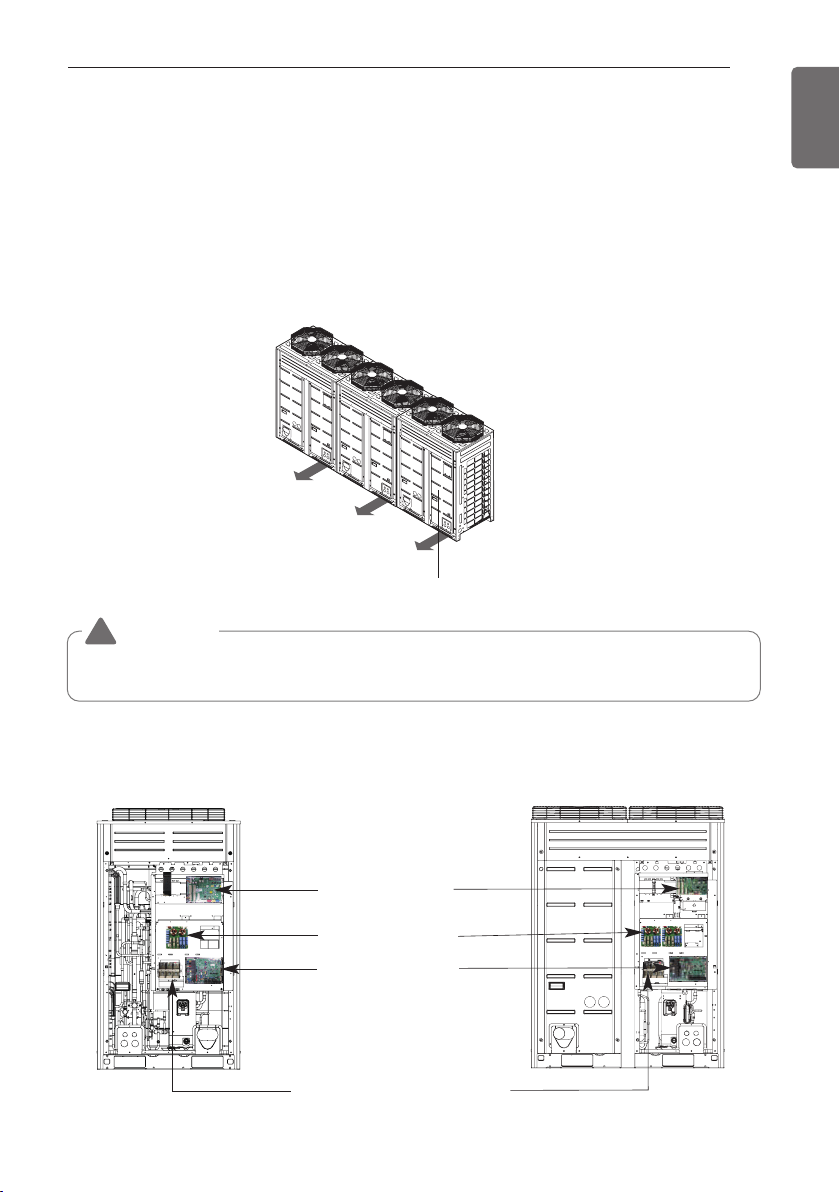
ELECTRICAL WIRING
63
ENGLISH
Control box and connecting position of wiring
- Remove all of the screws at front panel and remove the panel by pulling it forward.
- Connect communication cable between main and sub outdoor unit through the terminal block.
- Connect communication cables between outdoor unit and indoor units through the terminal
block.
- When the central control system is connected to the outdoor unit, a dedicated PCB must be
connected between them.
- When connecting communication cable between outdoor unit and indoor units with shielded
cable, connect the shield ground to the earth screw.
[Heat pump]
UX3
UX2
Front Panel
WARNING
The temperature sensor for outdoor air should not be exposed to direct sunlight.
- Provide an appropriate cover to intercept direct sunlight.
!
Main PCB
Noise Filter
External PCB
Take care of the phase
sequence of 3-phase 3-wire
power system

64
ELECTRICAL WIRING
ENGLISH
Communication and Power Cables
Communication cable
- Types : shielding cable
- Cross section : 1.0~1.5mm
2
(1.55 x 10
-3
~2.32 x 10
-3
in
2
)
- Maximum allowable temperature: 140°F
- Maximum allowable cable length: under 1000m(3,281ft)
Remote control cable
- Types : 3-core cable
Central control cable
Separation of communication and power cables
- If communication and power cables are run alongside each other then there is a strong likeli-
hood of operational faults developing due to interference in the signal wiring caused by electro-
static and electromagnetic coupling.
The tables below indicates our recommendation as to appropriate spacing of communication
and power cables where these are to be run side by side
NOTE
!
• The figures are based on assumed length of parallel cabling up to 100m(328ft). For length
in excess of 100m(328ft) the figures will have to be recalculated in direct proportion to the
additional length of cable involved.
• If the power supply waveform continues to exhibit some distortion the recommended
spacing in the table should be increased.
- If the cable are laid inside conduits then the following point must also be taken into ac-
count when grouping various cable together for introduction into the conduits
- Power cable(including power supply to air conditioner) and communication cables
must not be laid inside the same
- In the same way, when grouping the power wires and communication cables should not
be bunched together.
Product type Cable type Diameter
ACP&AC Manager 2-core cable (Shielding cable)
1.0~1.5mm
2
(1.55 x 10
-3
~2.32 x 10
-3
in
2
)
AC Smart 2-core cable (Shielding cable)
1.0~1.5mm
2
(1.55 x 10
-3
~2.32 x 10
-3
in
2
)
Simple central controller 4-core cable (Shielding cable)
1.0~1.5mm
2
(1.55 x 10
-3
~2.32 x 10
-3
in
2
)
Current capacity of power cable Spacing
100V or more
10A 300mm(11-13/16inch)
50A 500mm(19-11/16inch)
100A 1,000mm(39-3/8inch)
Exceed 100A 1,500mm(59-1/16inch)
CAUTION
If apparatus is not properly earthed then there is always a risk of electric shocks, the earthing of
the apparatus must be carried out by a qualified person.
!
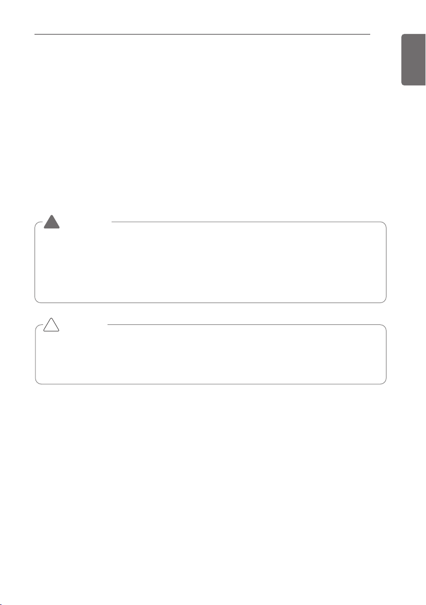
ELECTRICAL WIRING
65
ENGLISH
Wiring of main power supply and equipment capacity
- Use a separate power supply for the Outdoor Unit and Indoor Unit.
- Bear in mind ambient conditions (ambient temperature,direct sunlight, rain water,etc.) when
proceeding with the wiring and connections.
- The cable size is the minimum value for metal conduit wiring. The power cord size should be 1
rank thicker taking into account the line voltage drops. Make sure the power-supply voltage
does not drop more than 10%.
- Specific wiring requirements should adhere to the wiring regulations of the region.
- Power supply cords of parts of appliances for outdoor use should not be lighter than polychloro-
prene sheathed flexible cord.
- Don't install an individual switch or electrical outlet to disconnect each of indoor unit separately
from the power supply.
CAUTION
• Some installation site may require attachment of an earth leakage breaker. If no earth leakage
breaker is installed, it may cause an electric shock.
• Do not use anything other than breaker and fuse with correct capacity. Using fuse and wire or
copper wire with too large capacity may cause a malfunction of unit or fire.
!
WARNING
• Follow ordinance of your governmental organization for technical standard related to elec-
trical equipment, wiring regulations and guidance of each electric power company.
• Make sure to use specified cables for connections so that no external force is imparted to
terminal connections. If connections are not fixed firmly, it may cause heating or fire.
• Make sure to use the appropriate type of overcurrent protection switch. Note that gener-
ated overcurrent may include some amount of direct current.
!
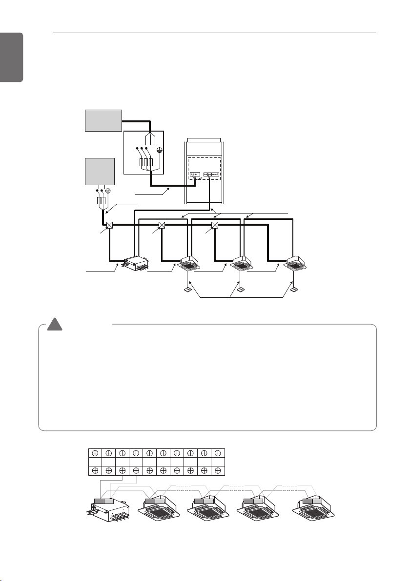
66
ELECTRICAL WIRING
ENGLISH
Field Wiring
208/230V
Example Connection of Communication Cable
1 Outdoor Unit-3Ø, 208/230V
Switch
ELCB
Communication Line
(2 Wires Cable)
Power Line
(3 Wires Cable)
Communication Line
(3 Wires Cable)
Power Line
(2 Wires Cable)
Power Line
ELCB
(2 Wires Cable)
Power Line
(2 Wires Cable)
Power Line
(2 Wires Cable)
Power Line
(2 Wires Cable)
[Outdoor Unit]
[Indoor Units]
Power supply
3 Phase 3 Wires
60Hz 208/230V
Power supply
1 Phase 60Hz
208/230V
(Main Switch)
Pull box
(Installer option)
Pull box
(Installer option)
Pull box
(Installer option)
HR unit
L(L1) N(L2)
RST
Between Indoor and Master Outdoor unit
HR unit
3(A) 4(B) 3(A) 4(B) 3(A) 4(B) 3(A) 4(B)
AB
Master
Outdoor Unit
SODU. B SODU. A IDU. B IDU. A CEN. B CEN. A DRY1 DRY2 GND 12V
WARNING
• Indoor Unit ground Lines are required for preventing electrical shock accident during current
leakage, Communication disorder by noise effect and motor current leakage (without connec-
tion to pipe).
• Don't install an individual switch or electrical outlet to disconnect each of indoor unit separately
from the power supply.
• Install the main switch that can interrupt all the power sources in an integrated manner because
this system consists of the equipment utilizing the multiple power sources.
• If there exists the possibility of reversed phase, lose phase, momentary blackout or the power
goes on and off while the product is operating, attach a reversed phase protection circuit locally.
Running the product in reversed phase may break the compressor and other parts.
!
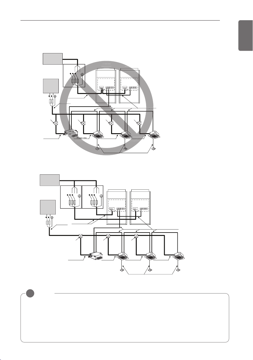
ELECTRICAL WIRING
67
ENGLISH
2 Outdoor Units-3Ø, 208/230V
When the power source is connected In series between the units.
When the power source is supplied to Each outdoor unit individually.
Communication Line
(2 Wires Cable)
Power Line
(3 Wires Cable)
Communication Line
(3 Wires Cable)
Power Line
(2 Wires Cable)
Power Line
(2 Wires Cable)
(2 Wires Cable)
Power Line
(2 Wires Cable)
Power Line
(2 Wires Cable)
[Master]
[Indoor Units]
(Main Switch)
[Slave]
Pull Box
(Installer option)
Pull Box
(Installer option)
Pull Box
(Installer option)
Pull Box
(Installer option)
nication L
es Cable
Com
Power
(2 Wires
(2 Wires C
r Line
(2 Wires Cab
[
Master]
[Sla
Power L
Wire
Power supply
3 Phase 3 Wires
60Hz 208/230V
Power supply
1 Phase 60Hz
208/230V
RST
Switch
ELCB
ELCB
L(L1) N(L2)
Switch
Communication Line
(2 Wires Cable)
Power Line
(3 Wires Cable)
Communication Line
(3 Wires Cable)
Power Line
(2 Wires Cable)
Power Line
(2 Wires Cable)
Power Line
(2 Wires Cable)
Power Line
(2 Wires Cable)
[Master]
[Indoor Units]
Power supply
3 Phase 3 Wires
60Hz 208/230V
Power supply
1 Phase 60Hz
208/230V
(Main Switch)
[Slave]
Switch
ELCBELCB
Pull box
(Installer option)
Pull box
(Installer option)
Pull box
(Installer option)
Power Line
(2 Wires Cable)
HR unit
ELCB
L(L1) N(L2)
RST RST
NOTE
!
- Field Wiring diagram is to be used as a guidelineonly. Wiring should comply with applica-
ble local and national codes
- ELCB must have function to prevent electrical short and over current at the same time .
- Use copper wires only.
- Unit must be grounded in compliance with the applicable local and national codes.
- ELCB and fuse/breaker must install to the power line
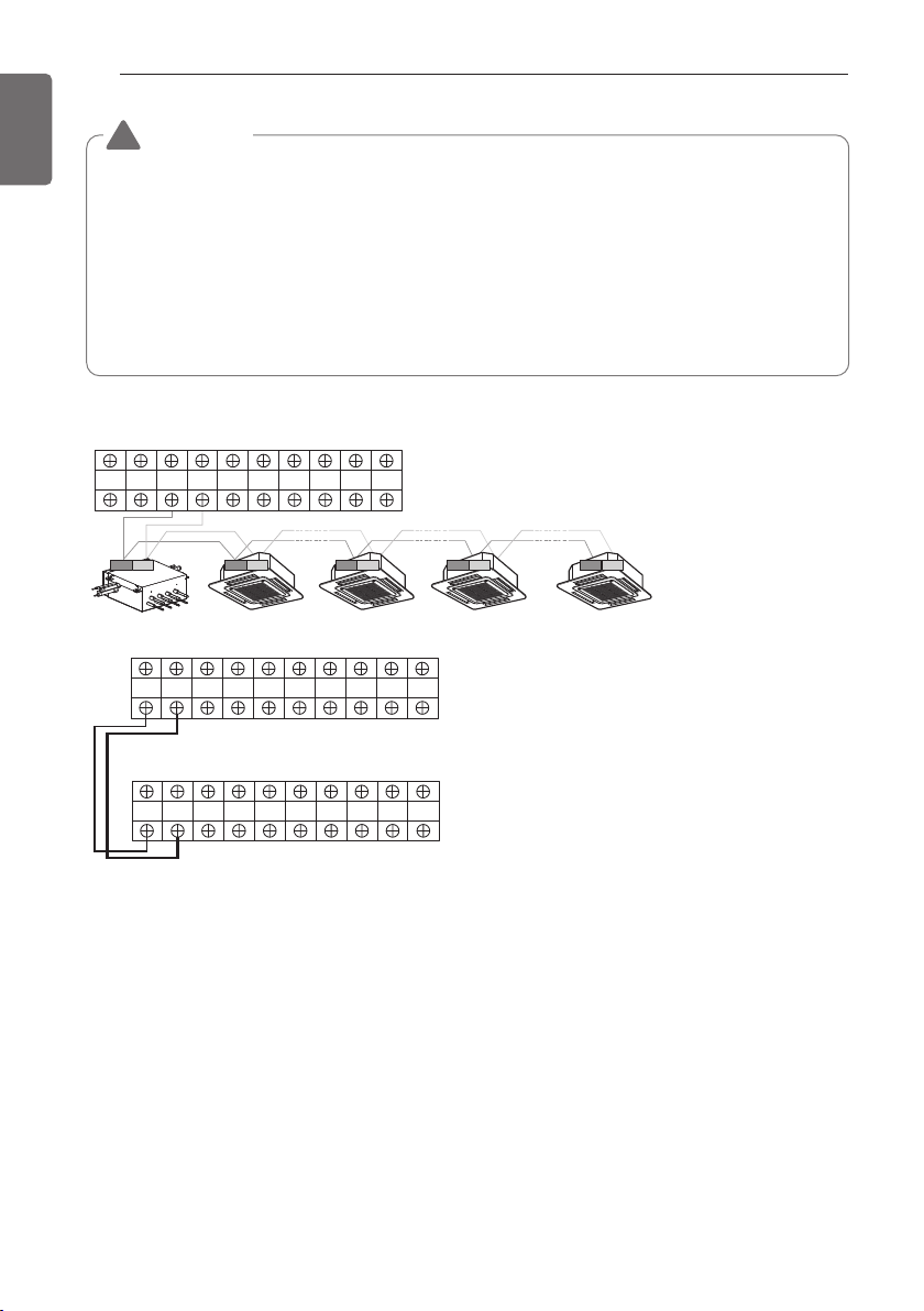
68
ELECTRICAL WIRING
ENGLISH
Master
Outdoor Unit
SODU. B SODU. A IDU. B IDU. A CEN. B CEN. A DRY1 DRY2 GND 12V
SODU. B SODU. A IDU. B IDU. A CEN. B CEN. A DRY1 DRY2 GND 12V
Slave
Outdoor Unit
HR unit
AB
3(A) 4(B) 3(A) 4(B) 3(A) 4(B) 3(A) 4(B)
Master
Outdoor Unit
SODU. B SODU. A IDU. B IDU. A CEN. B CEN. A DRY1 DRY2 GND 12V
Between Indoor and Master Outdoor unit
• It is not the point to make ground connection.
- Make sure that terminal number of master and slave outdoor units are matched.(A-A,B-B)
WARNING
• Indoor Unit ground Lines are required for preventing electrical shock accident during current
leakage, Communication disorder by noise effect and motor current leakage (without connec-
tion to pipe).
• Don't install an individual switch or electrical outlet to disconnect each of indoor unit separately
from the power supply.
• Install the main switch that can interrupt all the power sources in an integrated manner because
this system consists of the equipment utilizing the multiple power sources.
• If there exists the possibility of reversed phase, lose phase, momentary blackout or the power
goes on and off while the product is operating, attach a reversed phase protection circuit locally.
Running the product in reversed phase may break the compressor and other parts.
!
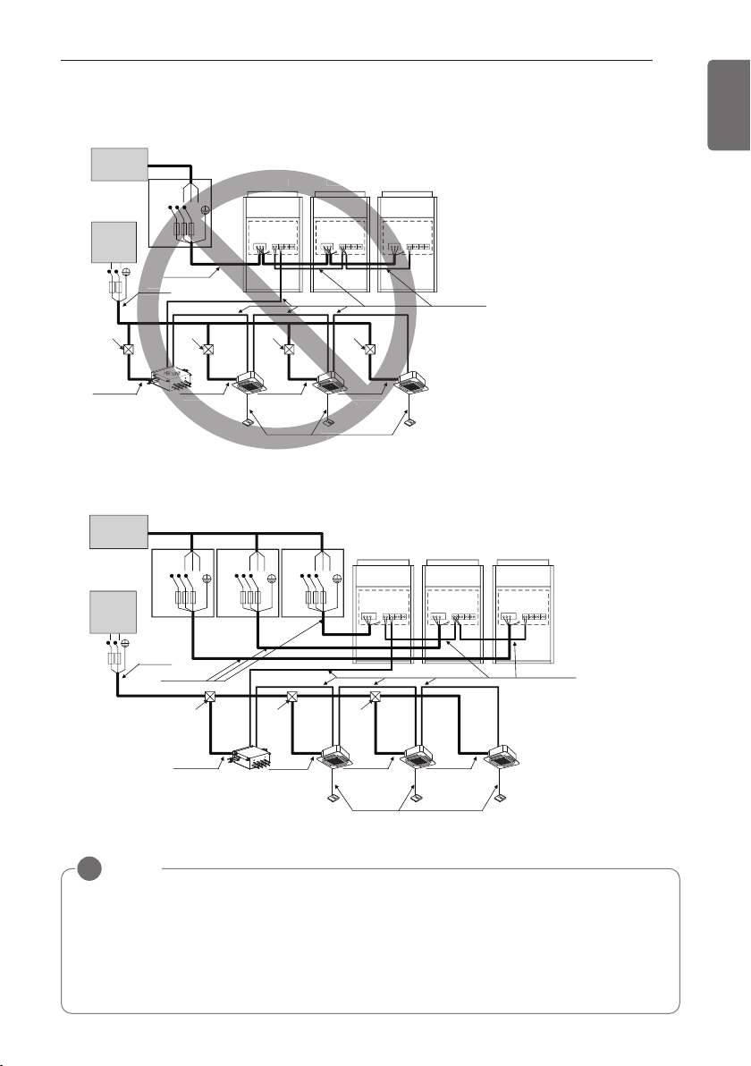
ELECTRICAL WIRING
69
ENGLISH
3 Outdoor Units-3Ø, 208/230V
When the power source is connected In series between the units.
Communication Line
(2 Wires Cable)
Power Line
(3 Wires Cable)
Communication Line
(3 Wires Cable)
Power Line
(2 Wires Cable)
Power Line
(2 Wires Cable)
Power Line
(2 Wires Cable)
Power Line
(2 Wires Cable)
Power Line
(2 Wires Cable)
[Master]
[Indoor Units]
(Main Switch)
[Slave1] [Slave2]
Pull Box
(Installer option)
Pull Box
(Installer option)
Pull Box
(Installer option)
Pull Box
(Installer option)
Communic
(3 W
Po
(2 Wire
ne
Cable)
Power
(2 Wires
[
Master
]
[Slav
Power Line
2 Wires Ca
)
Switch
ELCB
ELCB
Switch
Communication Line
(2 Wires Cable)
Power Line
(3 Wires Cable)
Communication Line
(3 Wires Cable)
Power Line
(2 Wires Cable)
Power Line
(2 Wires Cable)
Power Line
(2 Wires Cable)
Power Line
(2 Wires Cable)
[Master]
[Indoor Units]
Power supply
3 Phase 3 Wires
60Hz 208/230V
Power supply
1 Phase 60Hz
208/230V
Power supply
3 Phase 3 Wires
60Hz 208/230V
Power supply
1 Phase 60Hz
208/230V
(Main Switch)
[Slave1] [Slave2]
Switch Switch
ELCB ELCB ELCB
Pull box
(Installer option)
Pull box
(Installer option)
Pull box
(Installer option)
Power Line
(2 Wires Cable)
HR unit
ELCB
L(L1) N(L2)
L(L1) N(L2)
RST
RST RST RST
When the power source is supplied to Each outdoor unit individually.
NOTE
!
- Field Wiring diagram is to be used as a guidelineonly. Wiring should comply with applica-
ble local and national codes
- ELCB must have function to prevent electrical short and over current at the same time .
- Use copper wires only.
- Unit must be grounded in compliance with the applicable local and national codes.
- ELCB and fuse/breaker must install to the power line
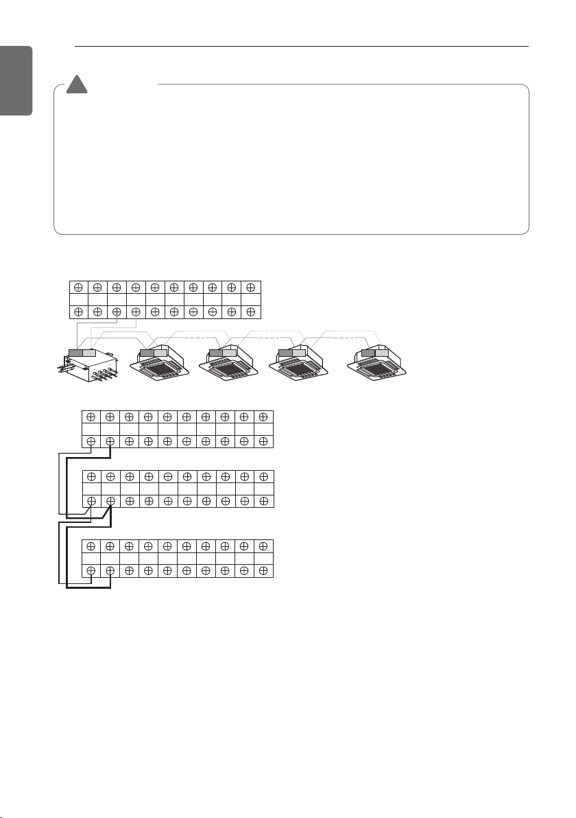
70
ELECTRICAL WIRING
ENGLISH
Master
Outdoor Unit
SODU. B SODU. A IDU. B IDU. A CEN. B CEN. A DRY1 DRY2 GND 12V
Master
Outdoor Unit
SODU. B SODU. A IDU. B IDU. A CEN. B CEN. A DRY1 DRY2 GND 12V
SODU. B SODU. A IDU. B IDU. A CEN. B CEN. A DRY1 DRY2 GND 12V
SODU. B SODU. A IDU. B IDU. A CEN. B CEN. A DRY1 DRY2 GND 12V
Slave1
Outdoor Unit
HR unit
Slave2
Outdoor Unit
AB
3(A) 4(B) 3(A) 4(B) 3(A) 4(B) 3(A) 4(B)
Between Indoor and Master Outdoor unit
• It is not the point to make ground connection.
- Make sure that terminal number of master and slave outdoor units are matched.(A-A,B-B)
WARNING
• Indoor Unit ground Lines are required for preventing electrical shock accident during current
leakage, Communication disorder by noise effect and motor current leakage (without connec-
tion to pipe).
• Don't install an individual switch or electrical outlet to disconnect each of indoor unit separately
from the power supply.
• Install the main switch that can interrupt all the power sources in an integrated manner because
this system consists of the equipment utilizing the multiple power sources.
• If there exists the possibility of reversed phase, lose phase, momentary blackout or the power
goes on and off while the product is operating, attach a reversed phase protection circuit locally.
Running the product in reversed phase may break the compressor and other parts.
!
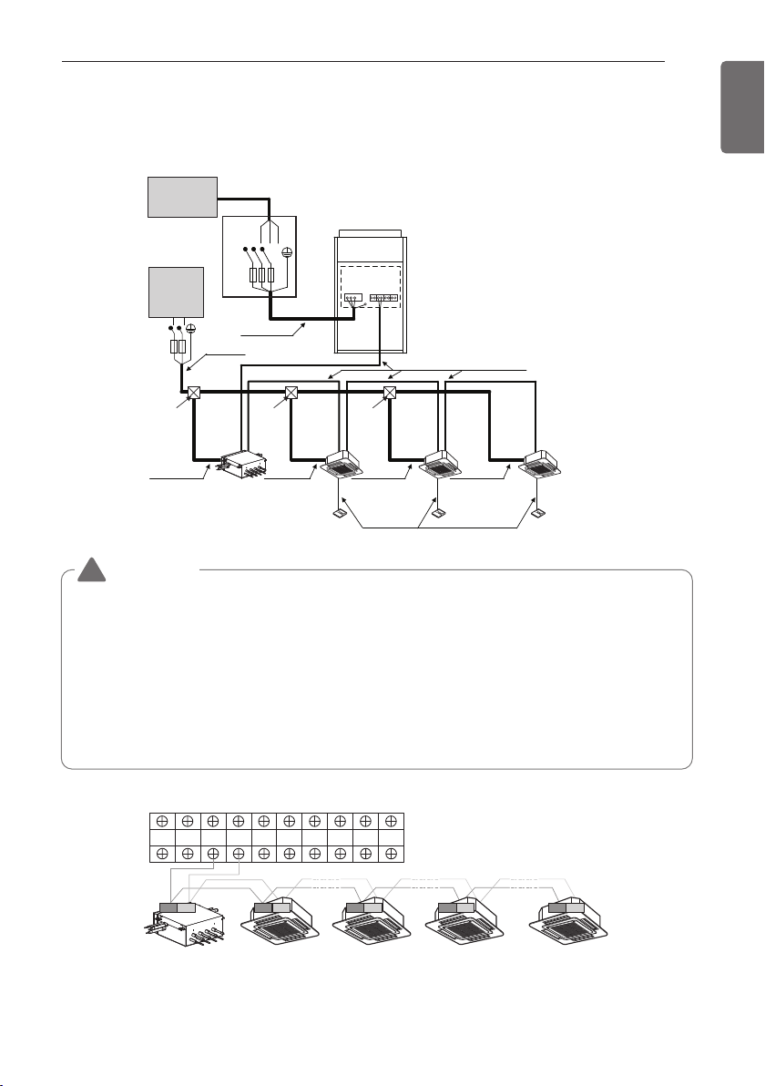
ELECTRICAL WIRING
71
ENGLISH
460V
Example Connection of Communication Cable
1 Outdoor Unit-3Ø, 460V
WARNING
• Indoor Unit ground Lines are required for preventing electrical shock accident during current
leakage, Communication disorder by noise effect and motor current leakage (without connec-
tion to pipe).
• Don't install an individual switch or electrical outlet to disconnect each of indoor unit separately
from the power supply.
• Install the main switch that can interrupt all the power sources in an integrated manner because
this system consists of the equipment utilizing the multiple power sources.
• If there exists the possibility of reversed phase, lose phase, momentary blackout or the power
goes on and off while the product is operating, attach a reversed phase protection circuit locally.
Running the product in reversed phase may break the compressor and other parts.
!
Switch
ELCB
Communication Line
(2 Wires Cable)
Power Line
(3 Wires Cable)
Communication Line
(3 Wires Cable)
Power Line
(2 Wires Cable)
Power Line
ELCB
(2 Wires Cable)
Power Line
(2 Wires Cable)
Power Line
(2 Wires Cable)
Power Line
(2 Wires Cable)
[Outdoor Unit]
[Indoor Units]
Power supply
3 Phase 3 Wires
60Hz 460V
Power supply
1 Phase 60Hz
208/230V
(Main Switch)
Pull box
(Installer option)
Pull box
(Installer option)
Pull box
(Installer option)
HR unit
L(L1) N(L2)
RST
Master
Outdoor Unit
SODU. B SODU. A IDU. B IDU. A CEN. B CEN. A DRY1 DRY2 GND 12V
Between Indoor and Master Outdoor unit
HR unit
AB
3(A) 4(B) 3(A) 4(B) 3(A) 4(B) 3(A) 4(B)
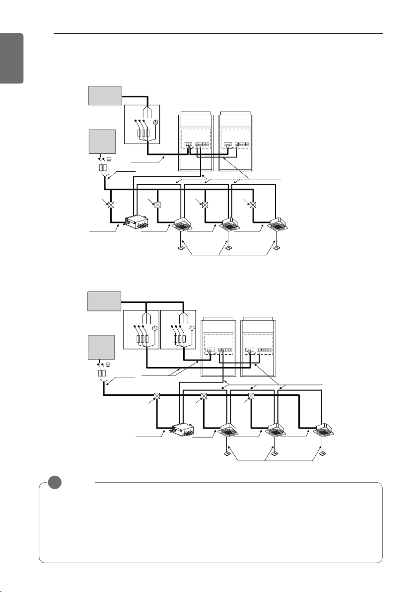
72
ELECTRICAL WIRING
ENGLISH
2 Outdoor Units-3Ø, 460V
When the power source is connected In series between the units.
Communication Line
(2 Wires Cable)
Power Line
(3 Wires Cable)
Communication Line
(3 Wires Cable)
Power Line
(2 Wires Cable)
Power Line
(2 Wires Cable)
Power Line
(2 Wires Cable)
Power Line
(2 Wires Cable)
Power Line
(2 Wires Cable)
[Master]
[Indoor Units]
(Main Switch)
[Slave]
Pull Box
(Installer option)
Pull Box
(Installer option)
Pull Box
(Installer option)
Pull Box
(Installer option)
HR unit
Power supply
3 Phase 3 Wires
60Hz 460V
Power supply
1 Phase 60Hz
208/230V
Switch
ELCB
ELCB
Switch
Communication Line
(2 Wires Cable)
Power Line
(3 Wires Cable)
Communication Line
(3 Wires Cable)
Power Line
(2 Wires Cable)
Power Line
(2 Wires Cable)
Power Line
(2 Wires Cable)
Power Line
(2 Wires Cable)
[Master]
[Indoor Units]
Power supply
3 Phase 3 Wires
60Hz 460V
Power supply
1 Phase 60Hz
208/230V
(Main Switch)
[Slave]
Switch
ELCBELCB
Pull box
(Installer option)
Pull box
(Installer option)
Pull box
(Installer option)
Power Line
(2 Wires Cable)
HR unit
ELCB
L(L1) N(L2)
L(L1) N(L2)
RST
RST RST
When the power source is supplied to Each outdoor unit individually.
NOTE
!
- Field Wiring diagram is to be used as a guideline only. Wiring should comply with applica-
ble local and national codes
- ELCB must have function to prevent electrical short and over current at the same time .
- Use copper wires only.
- Unit must be grounded in compliance with the applicable local and national codes.
- ELCB and fuse/breaker must install to the power line
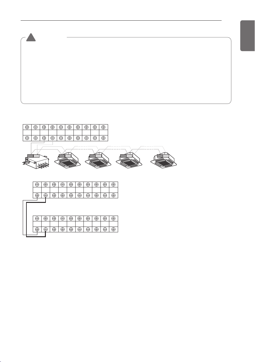
ELECTRICAL WIRING
73
ENGLISH
Master
Outdoor Unit
SODU. B SODU. A IDU. B IDU. A CEN. B CEN. A DRY1 DRY2 GND 12V
Slave
Outdoor Unit
SODU. B SODU. A IDU. B IDU. A CEN. B CEN. A DRY1 DRY2 GND 12V
Master
Outdoor Unit
SODU. B SODU. A IDU. B IDU. A CEN. B CEN. A DRY1 DRY2 GND 12V
HR unit
AB
3(A) 4(B) 3(A) 4(B) 3(A) 4(B) 3(A) 4(B)
Between Indoor and Master Outdoor unit
• It is not the point to make ground connection.
- Make sure that terminal number of master and slave outdoor units are matched.(A-A,B-B)
WARNING
• Indoor Unit ground Lines are required for preventing electrical shock accident during current
leakage, Communication disorder by noise effect and motor current leakage (without connec-
tion to pipe).
• Don't install an individual switch or electrical outlet to disconnect each of indoor unit separately
from the power supply.
• Install the main switch that can interrupt all the power sources in an integrated manner because
this system consists of the equipment utilizing the multiple power sources.
• If there exists the possibility of reversed phase, lose phase, momentary blackout or the power
goes on and off while the product is operating, attach a reversed phase protection circuit locally.
Running the product in reversed phase may break the compressor and other parts.
!
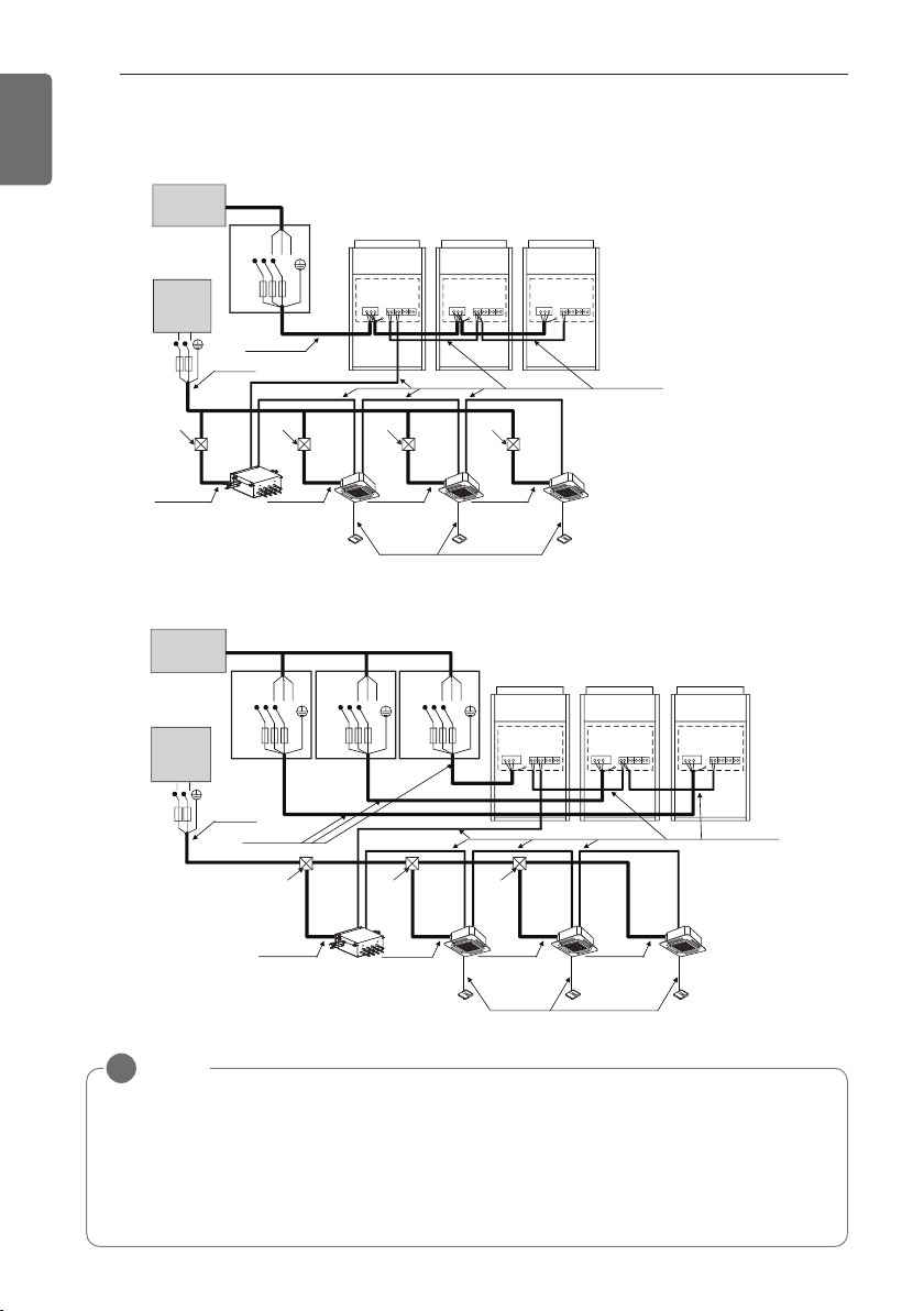
74
ELECTRICAL WIRING
ENGLISH
3 Outdoor Units-3Ø, 460V
When the power source is connected In series between the units.
Communication Line
(2 Wires Cable)
Power Line
(3 Wires Cable)
Communication Line
(3 Wires Cable)
Power Line
(2 Wires Cable)
Power Line
(2 Wires Cable)
Power Line
(2 Wires Cable)
Power Line
(2 Wires Cable)
Power Line
(2 Wires Cable)
[Master]
[Indoor Units]
(Main Switch)
[Slave1] [Slave2]
Pull Box
(Installer option)
Pull Box
(Installer option)
Pull Box
(Installer option)
Pull Box
(Installer option)
HR unit
Switch
ELCB
ELCB
Switch
Communication Line
(2 Wires Cable)
Power Line
(3 Wires Cable)
Communication Line
(3 Wires Cable)
Power Line
(2 Wires Cable)
Power Line
(2 Wires Cable)
Power Line
(2 Wires Cable)
Power Line
(2 Wires Cable)
[Master]
[Indoor Units]
Power supply
3 Phase 3 Wires
60Hz 460V
Power supply
1 Phase 60Hz
208/230V
Power supply
3 Phase 3 Wires
60Hz 460V
Power supply
1 Phase 60Hz
208/230V
(Main Switch)
[Slave1] [Slave2]
Switch Switch
ELCB ELCB ELCB
Pull box
(Installer option)
Pull box
(Installer option)
Pull box
(Installer option)
Power Line
(2 Wires Cable)
HR unit
ELCB
L(L1) N(L2)
L(L1) N(L2)
RST
RST RST RST
When the power source is supplied to Each outdoor unit individually.
NOTE
!
- Field Wiring diagram is to be used as a guideline only. Wiring should comply with applica-
ble local and national codes
- ELCB must have function to prevent electrical short and over current at the same time .
- Use copper wires only.
- Unit must be grounded in compliance with the applicable local and national codes.
- ELCB and fuse/breaker must install to the power line
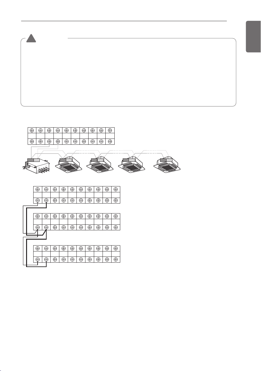
ELECTRICAL WIRING
75
ENGLISH
Master
Outdoor Unit
SODU. B SODU. A IDU. B IDU. A CEN. B CEN. A DRY1 DRY2 GND 12V
SODU. B SODU. A IDU. B IDU. A CEN. B CEN. A DRY1 DRY2 GND 12V
SODU. B SODU. A IDU. B IDU. A CEN. B CEN. A DRY1 DRY2 GND 12V
Master
Outdoor Unit
SODU. B SODU. A IDU. B IDU. A CEN. B CEN. A DRY1 DRY2 GND 12V
Slave1
Outdoor Unit
HR unit
AB
Slave2
Outdoor Unit
3(A) 4(B) 3(A) 4(B) 3(A) 4(B) 3(A) 4(B)
Between Indoor and Master Outdoor unit
• It is not the point to make ground connection.
- Make sure that terminal number of master and slave outdoor units are matched.(A-A,B-B)
WARNING
• Indoor Unit ground Lines are required for preventing electrical shock accident during current
leakage, Communication disorder by noise effect and motor current leakage (without connec-
tion to pipe).
• Don't install an individual switch or electrical outlet to disconnect each of indoor unit separately
from the power supply.
• Install the main switch that can interrupt all the power sources in an integrated manner because
this system consists of the equipment utilizing the multiple power sources.
• If there exists the possibility of reversed phase, lose phase, momentary blackout or the power
goes on and off while the product is operating, attach a reversed phase protection circuit locally.
Running the product in reversed phase may break the compressor and other parts.
!
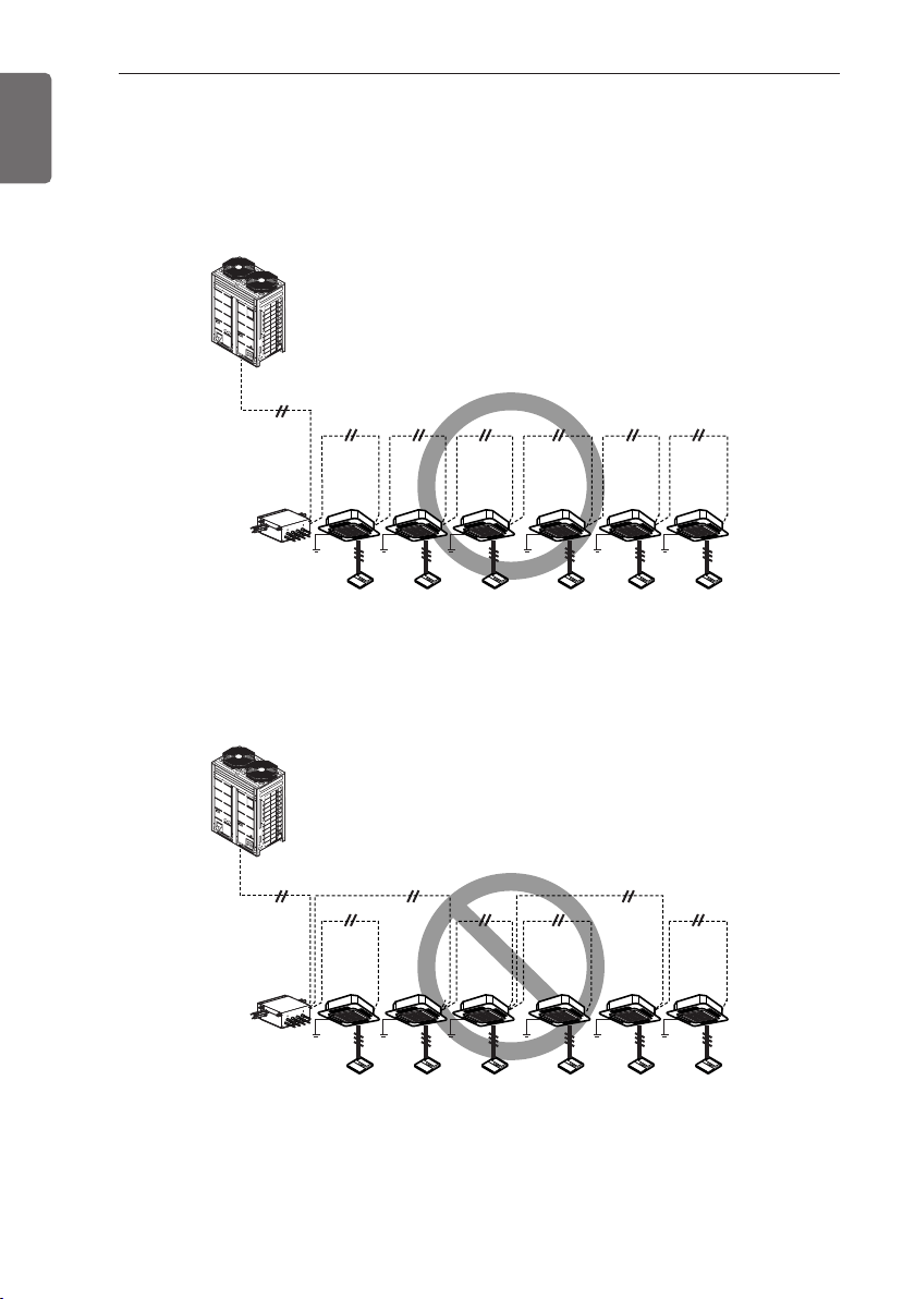
76
ELECTRICAL WIRING
ENGLISH
Example) Connection of transmission wire
[BUS type]
- Connection of communication cable must be installed like below figure between indoor unit to
outdoor unit.
MMMMMMM
MMMMMMM
[STAR type]
- Abnormal operation can be caused by communication defect, when connection of communica-
tion cable is installed like below figure(STAR type).
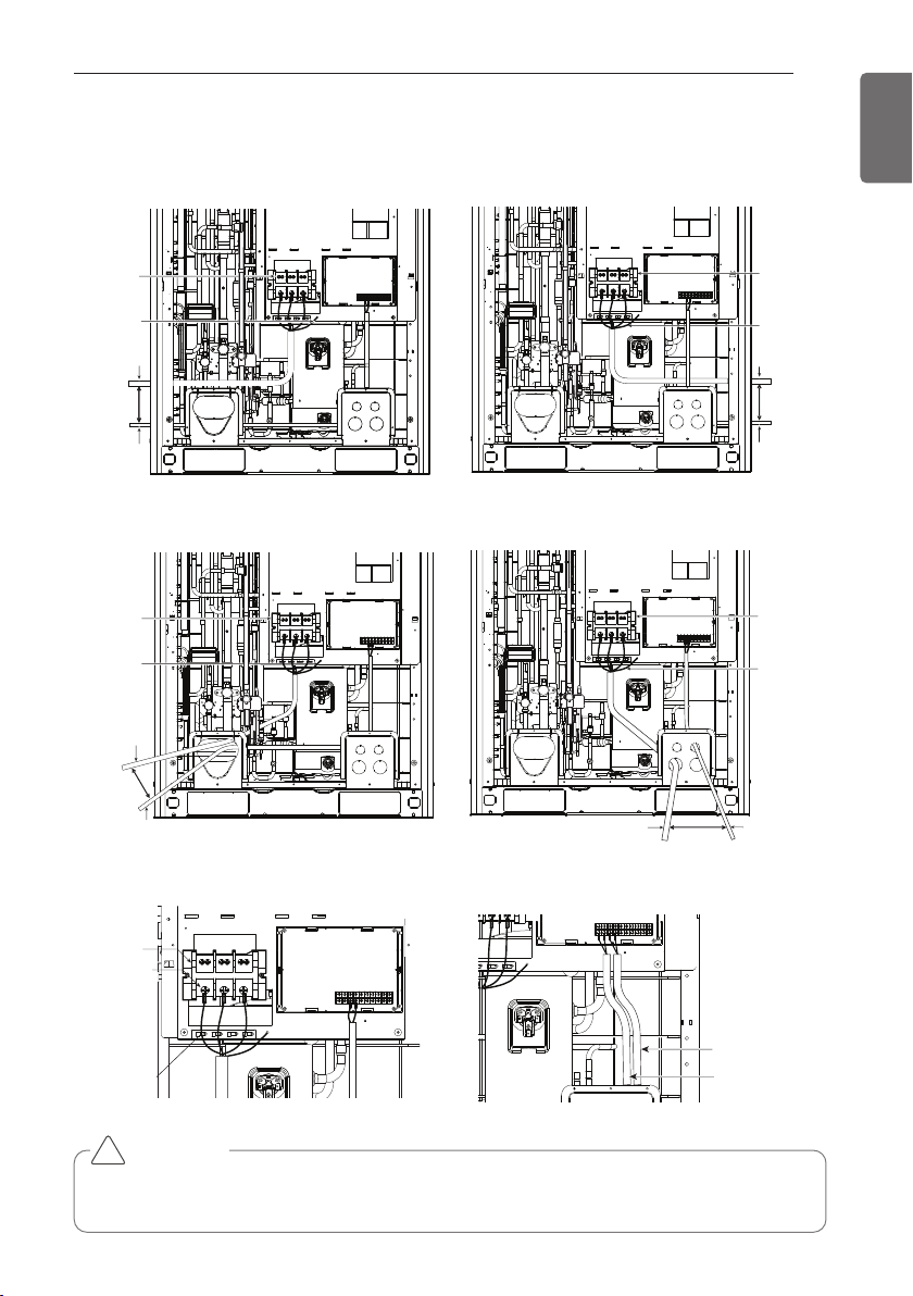
77
ENGLISH
ELECTRICAL WIRING
CAUTION
It should be wiring power cables or communication cables to avoid interference with the oil level
sensor. Otherwise, That oil level sensor would be operated abnormally.
!
Example) Connection of power and communication cable (UX2)
Main power
terminal block
Ground wire
Power/
Ground cable
Over
50mm(1.97”)
gap
Communication
cable
Main power
terminal block
Ground wire
Power/
Ground cable
Over
50mm(1.97”)
gap
Communication
cable
Main power
terminal block
Ground wire
Power/
Ground cable
Over
50mm(1.97”)
gap
Communication cable
Fix firmly not
to be displaced
Main power
terminal block
Insulation sleeves
attachments
ODU-IDU
Communication cable
ODU-ODU
Communication cable
Main power
terminal block
Ground wire
Power/Ground cable
Over
50mm(1.97”) gap
Communication
cable
Left Side Right Side
Front Side 1 Front Side 2
Main Power Connection Communication Connection
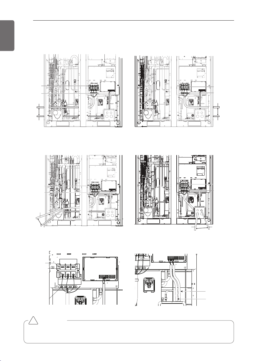
78
ENGLISH
ELECTRICAL WIRING
CAUTION
It should be wiring power cables or communication cables to avoid interference with the oil level
sensor. Otherwise, That oil level sensor would be operated abnormally.
!
Example) Connection of power and communication cable (UX3)
Main power
terminal block
Ground wire
Power/
Ground cable
Over 50mm
(1.97”)gap
Communication
cable
e
wer
Main power
terminal block
Ground wire
Power/
Ground cable
Over 50mm
(1.97”)gap
Communication
cable
e
wer
Main power
terminal block
Ground wire
Power/
Ground cable
Over 50mm
(1.97”)gap
Communication cable
Main power
terminal block
Insulation sleeves
attachments
Fix firmly not
to be displaced
ODU-IDU
Communication cable
ODU-ODU
Communication cable
e
wer
Main power
terminal block
Ground wire
Power/Ground cable
Over
50mm (1.97”)gap
Communication
cable
Left Side Right Side
Front Side 1 Front Side 2
Main Power Connection Communication Connection
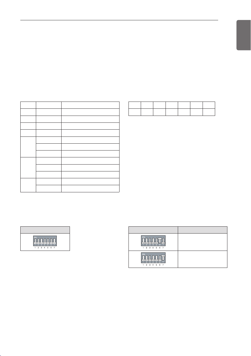
79
ENGLISH
ELECTRICAL WIRING
Checking the setting of outdoor units
Checking according to dip switch setting
- You can check the setting values of the Master outdoor unit from the 7 segment LED.
The dip switch setting should be changed when the power is OFF.
Checking the initial display
The number is sequentially appeared at the 7 segment in 5 seconds after applying the power.
This number represents the setting condition. (For example, represents R410A 36HP)
• Initial display order • Example) ARUB360BTE4
• Master Unit • Slave Unit
Dip switch setting Dip switch setting ODU Setting
Slave 1
Slave 2
Order No Mean
①
8~18
Master model capacity(HP)
②
8~14
Slave 1 model capacity(HP)
③
8~14
Slave 2 model capacity(HP)
④
8~36
Total capacity(HP)
⑤
1 Cooling Only
2 Heat Pump
3 Heat Recovery
⑥
38 380V model
46 460V model
22 220V model
⑦
1 Full function
2 Core function
① ② ③ ④ ⑤ ⑥ ⑦
14 12 10 36 3 22 1

80
HR UNIT PCB
ENGLISH
HR UNIT PCB
SW02M
(Dip switch for setup of
the function of HR unit)
SW03M SW04M
SW01M/SW03M/SW04M
(Switch for manual valve
addressing)
SW01M
SW05M
(Switch for
addressing
HR unit)
7-SEG
#1 valve housing
#1 cooling valve
LED(green)
#4 valve housing
Switch for setup of HR Unit
1 Main function of SW02M
ON S/W Selection
No.1 Method for pipe detection of an HR unit (Auto/Manual)
No.2 Model of HR unit
No.3 Model of HR unit
No.4 Model of HR unit
No.5 Valve group setting
No.6 Valve group setting
No.7
Use only in factory production (preset to “OFF”)
Zoning setting
(“ON”)
No.8
Use only in factory production (preset to “OFF”)
SW02M
1) Selection of the method for pipe detection of an HR unit (Auto/Manual)
Auto Manual
Switch No.1 OnSwitch No.1 Off
2) Setting the zoning control
DIP S/W setting
Normal
control
SW01M
Zoning
control
SW01M
Turn the dip switch of the zoning
branch on.
EX) Branch 1,2 are zoning control.
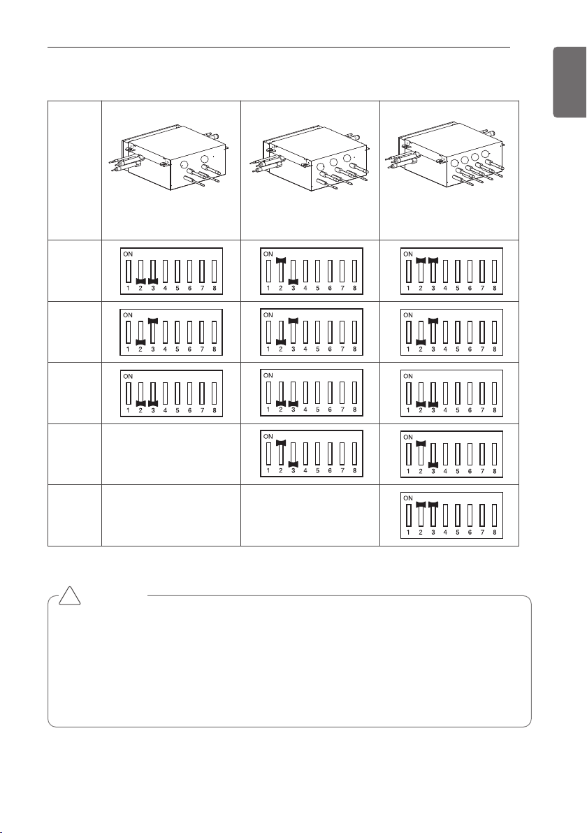
HR UNIT PCB
81
ENGLISH
3) Selection of the model of the HR unit
(For 2 branches)
PRHR021A
(For 3 branches)
PRHR031A
(For 4 branches)
PRHR041A
Initial
Setting
1 branches
Connected
2 branches
Connected
3 branches
Connected
4 branches
Connected
1
2
3
1
2
1
3
2
4
* Each model is shipped with the switches No.2 and No.3 pre-adjusted as above in the factory.
CAUTION
• If you want to use a PRHR031A for 2 branches HR unit after closing the 3rd pipes, set the dip
switch for 2 branches HR unit.
• If you want to use a PRHR041A for 3 branches HR unit after closing the 4th pipes, set the dip
switch for 3 branches HR unit.
• If you want to use a PRHR041A for 2 branches HR unit after closing the 3rd and 4th pipes, set
the dip switch for 2 branches HR unit.
• The unused port must be closed with a copper cap, not with a plastic cap.
!
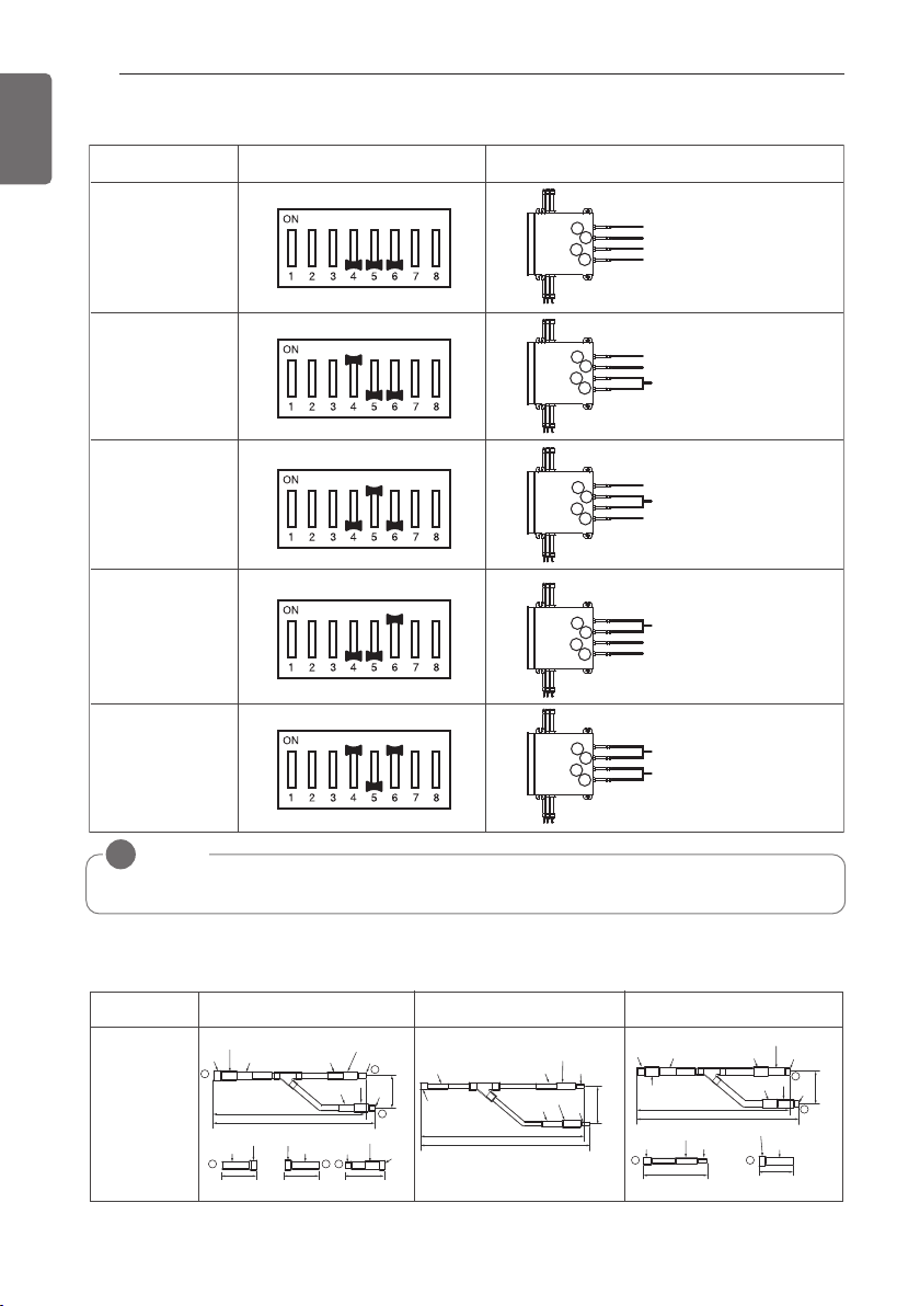
82
HR UNIT PCB
ENGLISH
4) Setting the Valve Group.
No.1, 2 Valve
/
No.3, 4 Valve
Control
No.3, 4 Valve
Control
DIP S/W setting
No.2, 3 Valve
Control
No.1, 2 Valve
Control
Not control
Example
Large capacity indoor unit
Large capacity indoor unit
1
2
3
4
Indoor Unit
Indoor Unit
Large capacity indoor unit
1
2
3
4
Indoor Unit
Indoor Unit
Large capacity indoor unit
1
2
3
4
Indoor Unit
Indoor Unit
Large capacity indoor unit
1
2
3
4
Indoor Unit
Indoor Unit
Indoor Unit
Indoor Unit
1
2
3
4
NOTE
!
If the large capacity indoor units are installed, below Y branch pipe should be used
Y branch pipe
Models
ARBLB03321
413(16-1/4)
390(15-11/32)
I.D19.05(3/4)
I.D19.05(3/4)
I.D19.05(3/4)
I.D15.88(5/8)
I.D12.7(1/2)
I.D12.7(1/2)
I.D12.7(1/2)
I.D12.7(1/2)
I.D12.7(1/2)
I.D12.7(1/2)
I.D12.7
(1/2)
74
(2-29/32)
70(2-3/4)
70(2-3/4)
I.D15.88(5/8)
I.D15.88(5/8)
I.D25.4(1)
I.D25.4(1)
I.D25.4(1)
O.D25.4(1)
80(3-5/32)
110(4-11/32) 110(4-11/32)
332(13-1/16)
321(12-5/8)
83
(3-9/32)
1
2
3
3
I.D19.05(3/4)
I.D19.05(3/4)
O.D19.05(3/4)
O.D19.05(3/4)
2
3 2
3
1 2
O.D15.88(5/8)
444(17-15/32)
421(16-9/16)
96
(3-25/32)
I.D15.88
(5/8)
I.D22.2(7/8)
I.D22.2(7/8)
I.D22.2(7/8)
I.D22.2(7/8)
I.D22.2(7/8)
I.D22.2(7/8)
O.D15.88(5/8)
I.D6.35(1/4)
I.D6.35(1/4)
I.D28.58(1-1/8)
I.D19.05(3/4)
I.D9.52(3/8)
I.D9.52(3/8)
I.D9.52(3/8)
I.D9.52(3/8)
Low Pressure Gas Pipe High Pressure Gas PipeLiquid pipe
[Unit : mm(inch)]
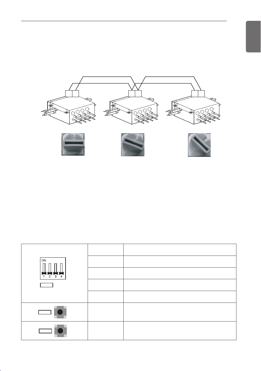
HR UNIT PCB
83
ENGLISH
2 SW05M (Rotary S/W for addressing HR unit)
Must be set to '0' when installing only one HR unit.
When installing multiple HR units, address the HR units with sequentially increasing numbers
starting from '0'.
Ex) Installation of 3 HR units
1
2
3
4
1
2
3
4
1
2
3
4
AB AB AB
3
SW01M/SW03M/SW04M (Dip S/W and tact S/W for manual valve addressing)
1) Normal setting (Non-Zoning setting)
- Set the address of the valve of the HR unit to the central control address of the connected in-
door unit.
- SW01M: selection of the valve to address
SW03M: increase in the digit of 10 of valve address
SW04M: increase in the last digit of valve address
- Prerequisite for manual valve addressing : central control address of each indoor unit must be
preset differently at its wired remote control.
S/W No. Setup
No.1 Manual addressing of valve #1
No.2 Manual addressing of valve #2
No.3 Manual addressing of valve #3
No.4 Manual addressing of valve #4
SW03M Increase in the digit of 10 of valve address
SW04M Increase in the last digit of valve address
SW01M
SW03M
SW04M
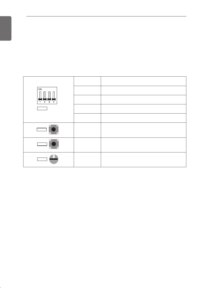
84
HR UNIT PCB
ENGLISH
2) Zoning setting
- Set the address of the valve of the HR unit to the central control address of the connected in-
door unit.
- SW01M : selection of the valve to address
SW03M : increase in the digit of 10 of valve address
SW04M : increase in the last digit of valve address
SW05M :Rotary S/W
- Prerequisite for manual valve addressing : central control address of each indoor unit must be
preset differently at its wired remote control.
S/W No. Setup
No.1 Manual addressing of valve #1
No.2 Manual addressing of valve #2
No.3 Manual addressing of valve #3
No.4 Manual addressing of valve #4
SW03M Increase in the digit of 10 of valve address
SW04M Increase in the last digit of valve address
SW05M Manual addressing of zoning indoor units
SW01M
SW03M
SW04M
SW05M
0
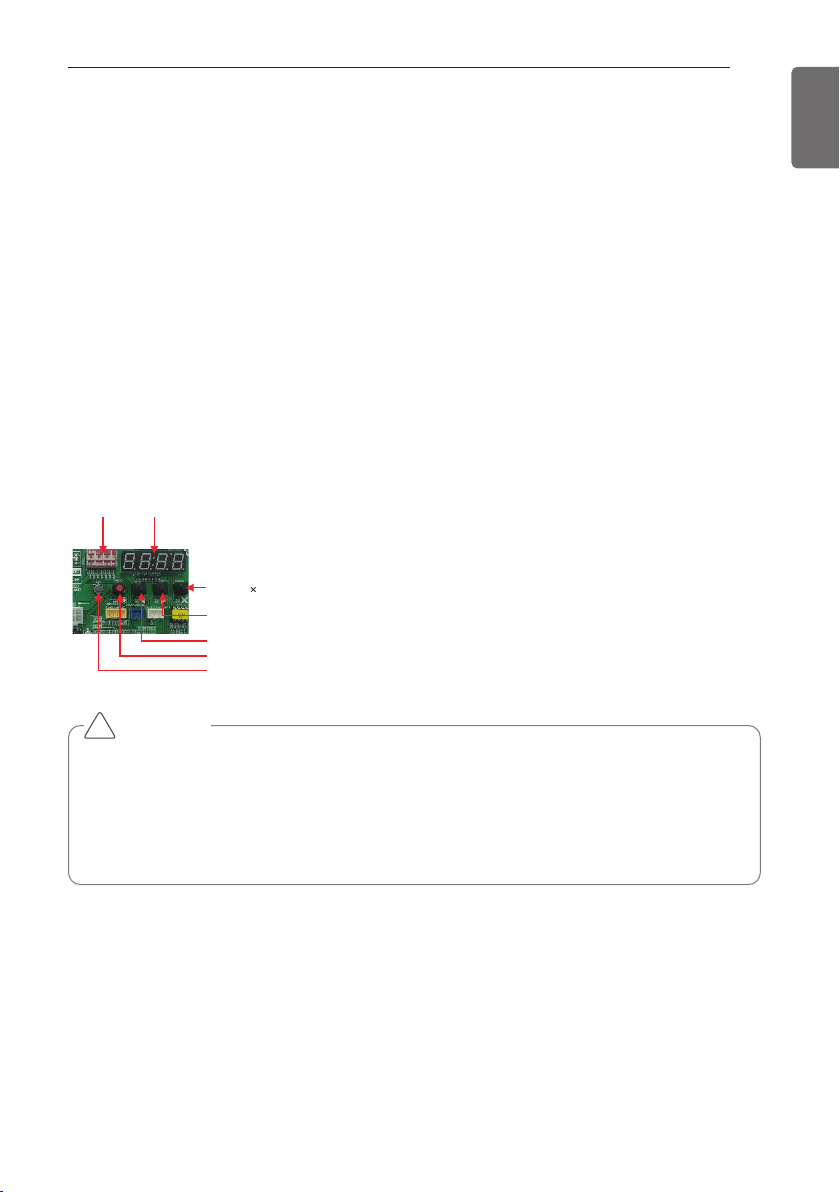
HR UNIT PCB
85
ENGLISH
Automatic Addressing
The address of indoor units would be set by Automatic Addressing
- Wait for 3 minutes after supplying power.
(Master and Slave outdoor units, indoor units)
- Press RED button of the outdoor units for 5 seconds. (SW01C)
- A “88” is indicated on 7-segment LED of the outdoor unit PCB.
- For completing addressing, 2~7 minutes are required depending on numbers of connected in-
door units
- Numbers of connected indoor units whose addressing is completed are indicated for 30 sec-
onds on 7-segment LED of the outdoor unit PCB
- After completing addressing, address of each indoor unit is indicated on the wired remote con-
trol display window. (CH01, CH02, CH03, ……, CH06 : Indicated as numbers of connected in-
door units)
[Heat Recovery (MAIN PCB)]
DIP-SWITCH 7 - Segment
SW01C ( : confirm)
SW02C (ඔ : backward)
SW03C (ඖ : forward)
SW04C (
: cancel)
SW01D (reset)
CAUTION
• In replacement of the indoor unit PCB, always perform Automatic addressing setting again (At
that time, please check about using Independent power module to any indoor unit.)
• If power supply is not applied to the indoor unit, operation error occur.
• Automatic Addressing is only possible on the master Unit.
• Automatic Addressing has to be performed after 3 minutes to improve communication.
!
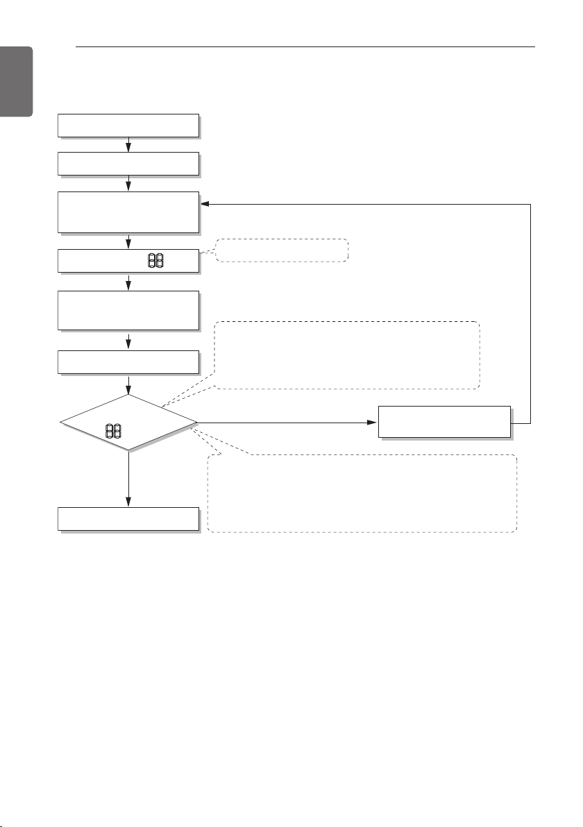
86
HR UNIT PCB
ENGLISH
The Procedure of Automatic Addressing
• Automatic addressing setting end
Numbers of indoor unit connection set whose
addressing is completed are indicated for 30seconds on
7-segment LED after completing setting
Indoor address number is displayed on wired remote control or
indoor unit display window. It is not an error message, will
disappeared when on/off button is pressed on remote control
ex) Display of 01, 02, ..., 15 means connection of 15 indoor units
and Automatic addressing is completed normally.
Automatic addressing start
Waiting 3 minutes
Power On
Press RED Button for 5 sec.
(SW01C)
7-segment LED = 88
Don’t press RED Button
(SW01C)
Waiting about 2~7 minutes
7-segment LED
OK
YES
NO Check the connections
of communication cable
= 88
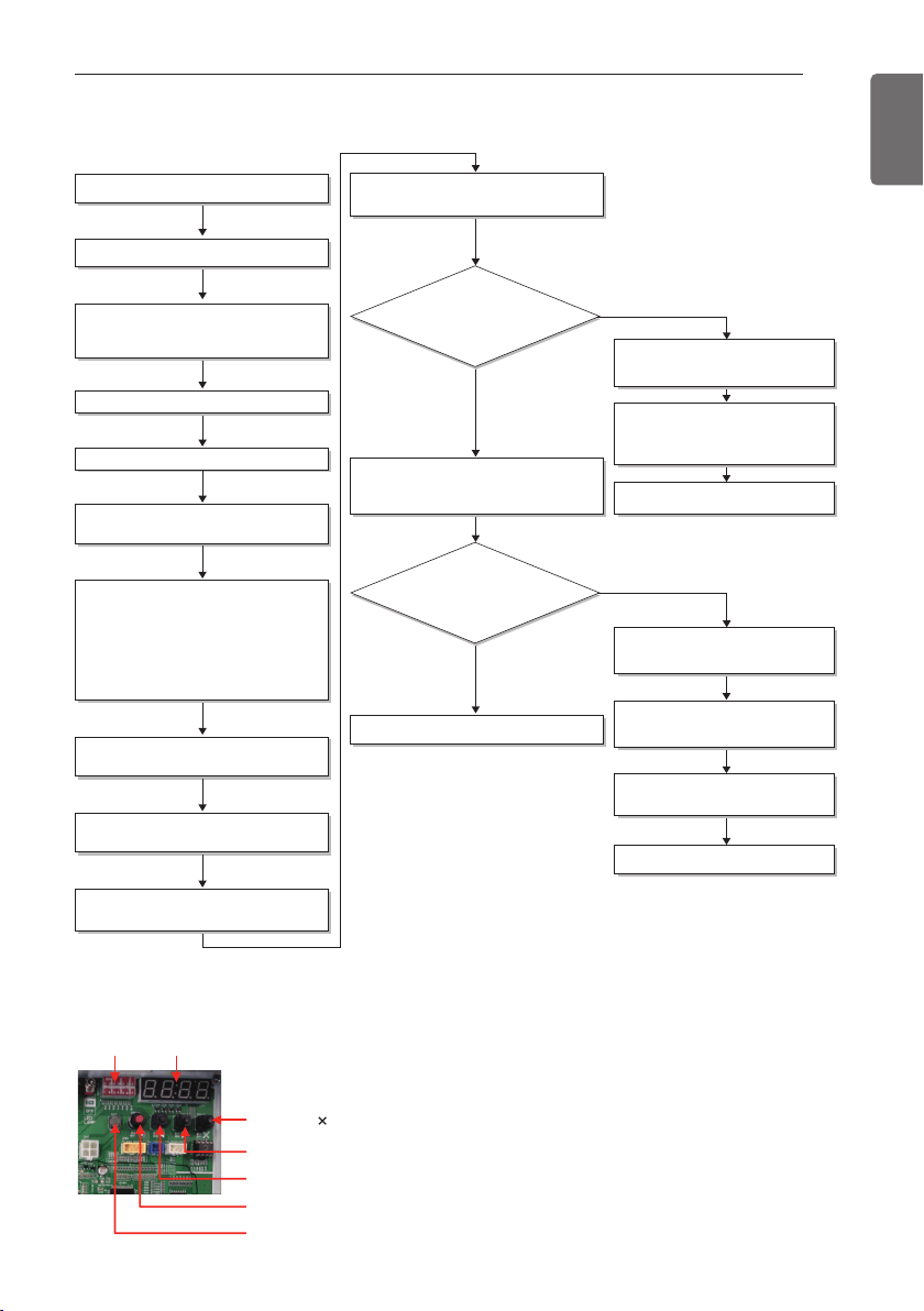
HR UNIT PCB
87
ENGLISH
Flow chart of auto addressing for pipe detection
Completion of auto pipe detection
Are the number
of indoor units connected to the
outdoor unit wiring and displayed
one equal?
Reset the power of HR unit PCB
Confirm that the setting of No.2, 3 of
SW02M corresponds with the number of
indoor units.
Master unit PCB DIP switch on : No.5
Select the mode using ‘ȯ’, ‘ȭ’ Button :
“Idu” Push the ‘Ɨ’ button
Select the mode using ‘ȯ’, ‘ȭ’ Button :
“Idu” Push the ‘Ɨ’ button
Select the “Id 6” function using ‘ȯ’, ‘ȭ’
Button :“StA” Push the ‘Ɨ’ button
Select the “Id 5” function using ‘ȯ’, ‘ȭ’
Button :“Ath” or ”Atc” Push the ‘Ɨ’
button.
Outdoor temperature is over 15°C(59°F) :
“Atc” Using
Outdoor temperature is below 15°C(59°F) :
“Ath” Using
88' is displayed on 7-SEG of the outdoor
unit main PCB
Outdoor unit is operated for 5~60 minues.
The number of indoor units detected is
displayed for 30 seconds on the outdoor
unit PCB after outdoor unit stopped
Display error on outdoor unit PCB
Display error on HR unit PCB
Outdoor unit PCB : HR
⇒
HR unit
number
⇒
Valve number
HR unit : '200'
Check the HR unit and indoor unit
Pipe detection error occur after 30
seconds.
Check the installation of pipe of
outdoor, indoor, HR unit
Incompletion of auto pipe detection
Retry auto pipe detection after
checking trouble
Is the pipe
setting condition
satisfied during the operation of
indoor unit?
Confirmation of indoor unit address setting
Turn No.1 of SW02M of HR unit PCB off.
NO
NO
YES
YES
※It is possible to be generated mode changing noise of heating and cooling which is normal.
There is no mode changing noise at normal operation.
DIP-SW01 7 - Segment
SW01C ( : confirm)
SW02C (ඔ : backward)
SW03C (ඖ : forward)
SW04C (
: cancel)
SW01D (reset)
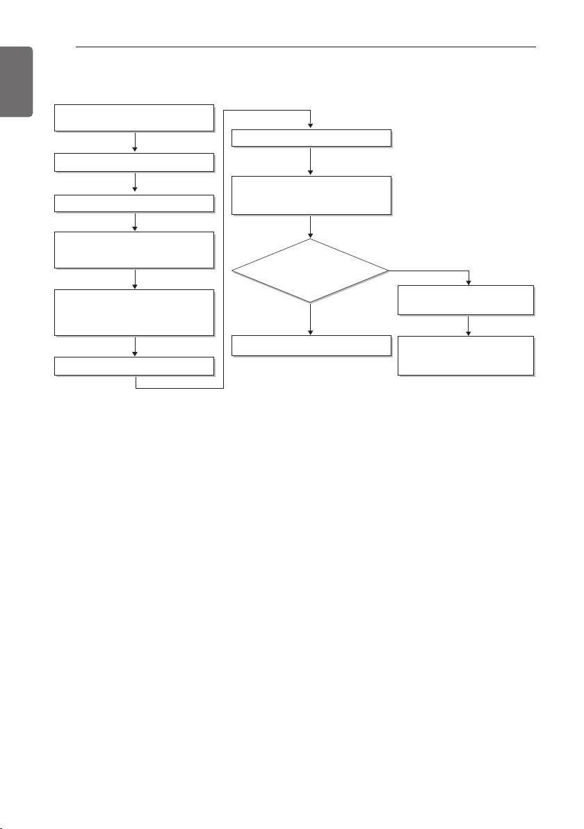
88
HR UNIT PCB
ENGLISH
Flow chart of manual addressing for pipe detection
Completion of manual pipe detection
Reset the power of HR unit PCB.
Enter the central control address into
each indoor unit using its wired remote
control.
On the HR unit PCB, manually set address
of each valve of the HR unit to the central
control address of the indoor unit
connected to the valve.
Reset the power of outdoor unit PCB.
Wait for about 5 minutes.
The number of the indoor units installed is
displayed.
Ex)HR
⇒
The number of the indoor
Check the central control address of
indoor and HR unit.
Make sure that reset the outdoor
unit power when changing the
central control unit
Are the number
of indoor units connected to the
outdoor unit and displayed one
equal?
Execute in case of Auto pipe detection
failure
Turn No.1 of SW02M of HR unit PCB on.
NO
YES
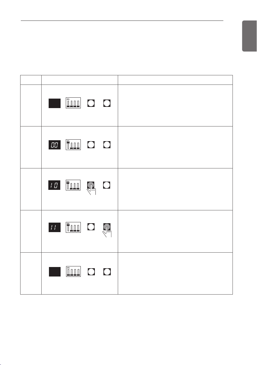
HR UNIT PCB
89
ENGLISH
Example of manual valve addressing (Non-Zoning setting)
(In case that an indoor unit of central control address "11" is connected to a valve #1 of an HR
unit)
- Prerequisite for manual valve addressing: central control address of each indoor unit must be
preset differently at its wired remote control.
- Operation: None
- Display: None
No.
1
2
3
4
5
Display and setup
Setup and Contents
- Operation: Turn dip S/W No.1 on to address valve
#1
- Display: Existing value saved in EEPROM is dis-
played in
7-SEG.
- Operation: Set the digit of 10 to the number in
Group High data of the wired remote control con-
nected to the corresponding indoor unit to the
valve #1 by pressing left tack S/W.
- Display: Digit increasing with the times of press-
ing tack S/W is displayed in left 7-SEG
- Operation: Set the digit of 1 to the number in
Group Low data of the wired remote control con-
nected to the corresponding indoor unit to the
valve #1 by pressing right tack S/W.
- Display: Digit increasing with the times of press-
ing tack S/W is displayed in right 7-SEG
- Operation: Turn dip S/W No.1 off to save the ad-
dress of
valve #1
- Display: "11" displayed in 7-SEG disappears
7-SEG SW01M SW03M SW04M
7-SEG SW01M SW03M SW04M
7-SEG SW01M SW03M SW04M
7-SEG SW01M SW03M SW04M
7-SEG SW01M SW03M SW04M
- Above setup must be done for all HR unit valves.
- The valve that is not connected with any indoor unit should be addressed with any other num-
ber than used address numbers of the valves connected with indoor units.
(The valves does not work if the address numbers are same.)
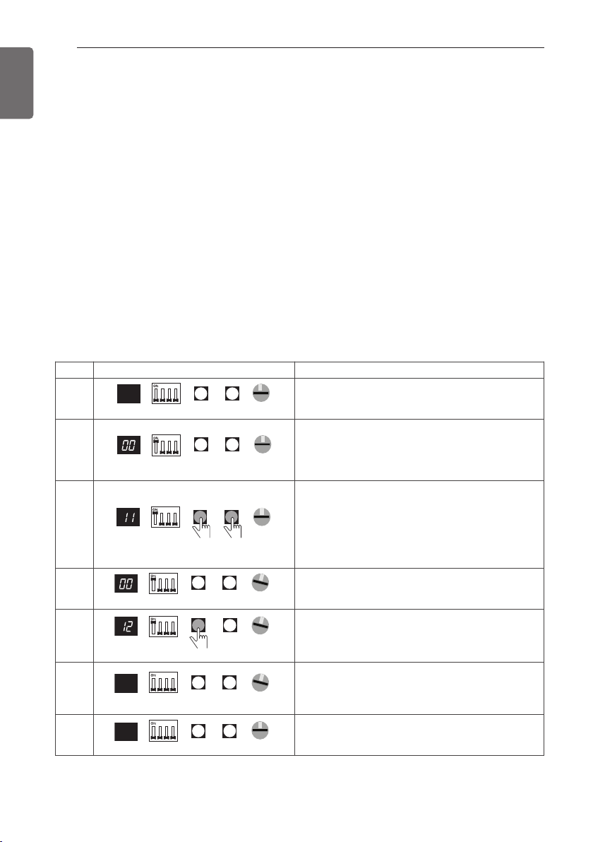
90
HR UNIT PCB
ENGLISH
Example of manual valve addressing (Zoning setting)
(In case that an indoor unit of central control address "11" is connected to a valve #1 of an HR unit)
Zoning control is connecting 2 or more indoor units at one pipe of HR unit. In case of Zoning control,
in order to set controls with multiple indoor units connection uses the rotary switch. Namely, only the
rotary switch changes from same valve set condition and set indoor units connection.
1) On dip switch of the corresponding valves and sets the rotary switch at 0.
2) Setting the number with tact switch.
3) In case of addition of indoor units to same port, increases 1 with the rotary switch and sets number
with tact switch.
4) In case of checking the number which the corresponding valve is stored, turn on dip switch and set
the number of rotary switch.
5) Indoor units set available 8 per a port(rotary switch 0~7), in case of setting above of 8 with rotary
switch, it will display error.
6) Setting the rotary switch on original condition(HR unit number set conditions) after all finishing a pip-
ing setting.
7) The rotary switch set value of above number of indoor units which is connected with FF and pre-
vents a malfunction.
(Example: The case where 3 indoor units is connected in piping 1, sets from rotary switch 0,1,2 and
3,4,5,6,7 with FF set)
- Prerequisite for manual valve addressing: central control address of each indoor unit must be pre-
set differently at its wired remote control.
No. Display and setup Setup and Contents
1
7-SEG SW01M SW03M SW04M
0
SW05M
- Operation: None
- Display: None
2
7-SEG SW01M SW03M SW04M
SW05M
0
- Operation : Turn dip S/W No.1 on to address
valve #1
- Display : Existing value saved in EEPROM is
displayed in 7-SEG.
3
- Operation : Set the digit of 10(1) to the number
in Group High data of the wired remote control
connected to the corresponding indoor unit to
the valve #1 by pressing left tack S/W.
- Display : Digit increasing with the times of
pressing tack S/W is displayed in left 7-SEG.
4
1
7-SEG SW01M SW03M SW04M
SW05M
- Operation : SW05M : 1
- Display : Display former value.
5
7-SEG SW01M SW03M SW04M
SW05M
1
- Operation : Setting No. using SW03M and
SW04M, SW05M : 1
- Display : Display setting value.
6
7-SEG SW01M SW03M SW04M
SW05M
1
- Operation : Turn dip S/W No.1 off to save the
address of valve #1
- Display : "11" displayed in 7-SEG disappears.
7
7-SEG SW01M SW03M SW04M
SW05M
0
- Operation : Return valve of addressing HR unit.
- Display : None
7-SEG SW01M SW03M SW04M
SW05M
0
- Above setup must be done for all HR unit valves.
- The valve that is not connected with any indoor unit should be addressed with any other num-
ber than used address numbers of the valves connected with indoor units.(The valves does not
work if the address numbers are same.)
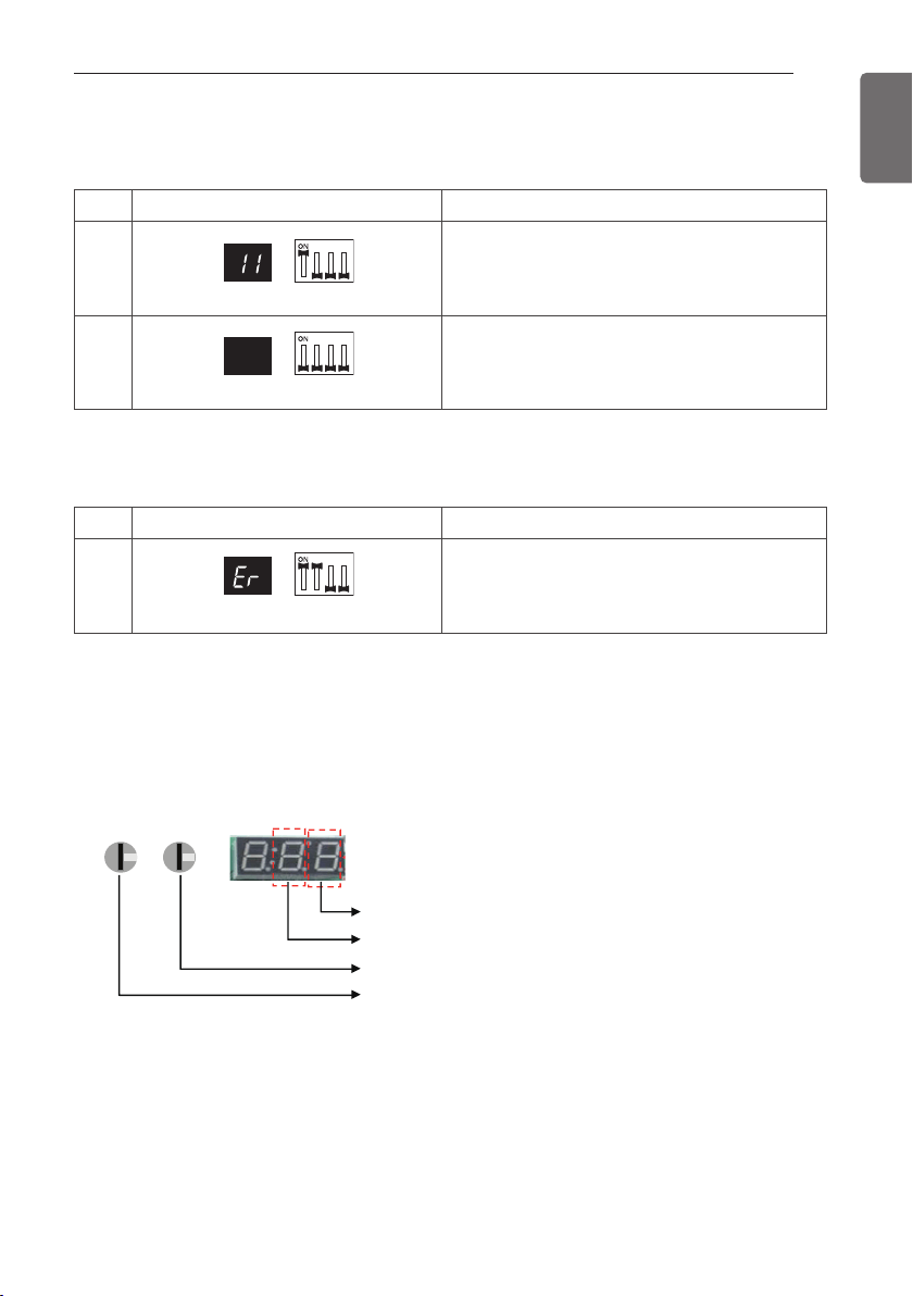
HR UNIT PCB
91
ENGLISH
Method of checking the pipe detection result at HR unit
In case that an indoor unit of central control address "11" is connected to a valve #1 of an HR unit
Identification of Manual Valve ID (Address)
Method of checking the pipe detection result at outdoor unit
1) Wait for 5 minutes, after Pipe detection is completed.
2) Turn on the No.10,14,16 DIP S/W of SUB PCB at master unit
3) Check the data on 7- segment, switching rotary 01,02.
No. Display and setup Setup and Contents
1
7-SEG SW01M
- Operation: Turn dip S/W No.1 on.
- Display: "11" is displayed in 7-SEG
2
7-SEG SW01M
- Operation: Turn dip S/W No.1 off.
- 7-SEG disappeared
No. Display and setup Setup and Contents
1
7-SEG SW01M
- Operation: more than 2 dip switches turned on.
- Display: "Er" is displayed in 7-SEG
ROTARY 01 ROTARY 02
0
0
The connected port number of HR unit
The connected HR unit number
The auto addressing number of indoor unit (digit of 1)
The auto addressing number of indoor unit (digit of 10)
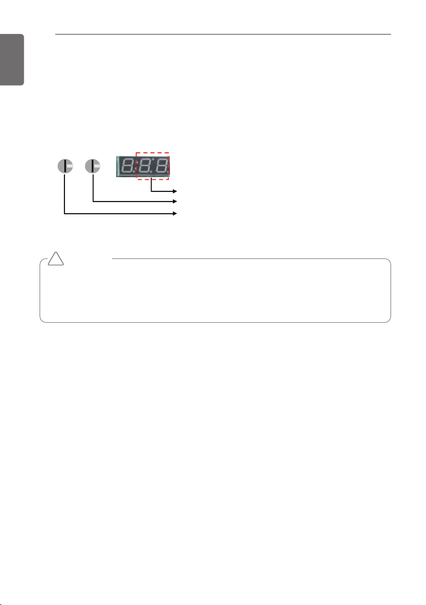
92
HR UNIT PCB
ENGLISH
Setting method of Master indoor unit in zoning
1 Turn dip switch 5,6,10 on at system off.
2 Set the left Rotary switch for HR unit.(Rotary switch No. "0" HR unit No. "1")
3 Set the right Rotary switch for IDU unit.(Rotary switch No. "0" HR unit branch No. "1")
4 Display the Master IDU No. of the HR unit on 7segment.(Default display is "00" on 7segment)
5 Press the black button.(The IDU No. increase every 1 second in the zoning )
6 Set the Master IDU(Press the red button during 1.5seconds stop twinkling)
ROTARY 01 ROTARY 02
0
0
No. of Indoor unit.
No. of HR unit branch.
No. of HR unit.
CAUTION
• Waiting for 80seconds after power on.
• The zoning information and Master IDU information remove from EEPROM after Auto-address-
ing.
• If there is installed the central control, it is impossible setting of Master IDU in zoning.
!
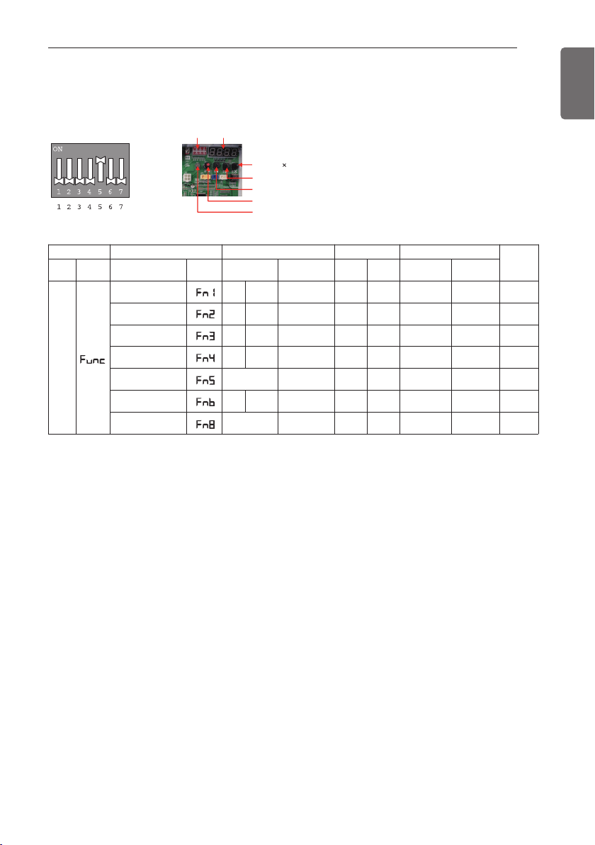
HR UNIT PCB
93
ENGLISH
MODE FUNCTION OPTION VALUE ACTION
remarks
con-
tent
Display1
content
Display2
content Display3
con-
tent
Display4
implement Display5
In-
stalla-
tion
Cool & Heat
Selector
oFF
op1~op2
selected the
option
- -
change the
set value
blank
save in
EEPROM
Static pressure
compensation
oFF
op1~op3
selected the
option
- -
change the
set value
blank
save in
EEPROM
Night low noise
oFF
op1~op12
selected the
option
- -
change the
set value
blank
save in
EEPROM
Overall defrost
on
oFF
selected the
option
- -
change the
set value
blank
save in
EEPROM
ODU address
-
-
0~255
set the
value
change the
set value
blank
save in
EEPROM
Snow removal &
rapid defrost
oFF
op1~op3
selected the
option
- -
change the
set value
blank
save in
EEPROM
Target pressure
adjusting
op1~op4
selected the
option
- -
change the
set value
blank
save in
EEPROM
* Functions save in EEPROM will be kept continuously, though the system power was reset.
Setting the function
Select the mode/function/option/value using ‘▶’, ‘◀’ Button and confirm that using the ‘●’ but-
ton after dip switch No.5 is turned on.
DIP-SW01 7 - Segment
SW01C ( : confirm)
SW02C (ඔ : backward)
SW03C (ඖ : forward)
SW04C (
: cancel)
SW01D (reset)
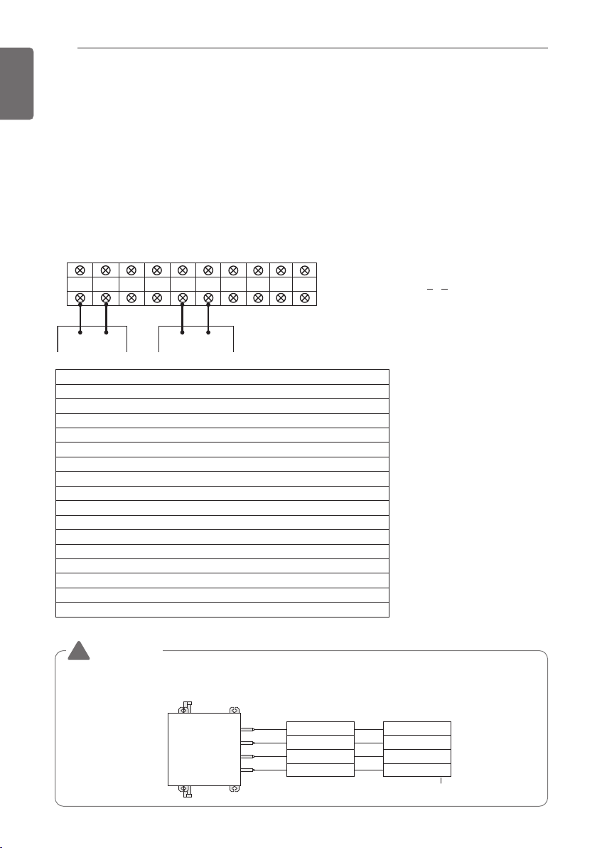
94
HR UNIT PCB
ENGLISH
Group Number setting
Group Number setting for Indoor Units
- Confirm the power of whole system(Indoor Unit, Outdoor Unit) is OFF, otherwise turn off.
- The communication cables connected to CEN.A and CEN.B terminal should be connected to
central control of Outdoor Unit with care for their polarity (A-A, B-B ).
- Turn the whole system on.
- Set the group and Indoor Unit number with a wired remote control.
- To control several sets of Indoor Units into a group, set the group ID from 0 to F for this pur-
pose.
Outdoor Units (External PCB)
Example) Group number setting
1
st
number indicate the group number
2nd number point out indoor unit number
SODU.B SODU.A IDU.B IDU.A CEN.B CEN.A DRY1 DRY2 GND 12V
B(D) A(C) BA
1 F
Group Indoor unit
Group recognizing the central controller
No.0 group (00~0F)
No.1 group (10~1F)
No.2 group (20~2F)
No.3 group (30~3F)
No.4 group (40~4F)
No.5 group (50~5F)
No.6 group (60~6F)
No.7 group (70~7F)
No.8 group (80~8F)
No.9 group (90~9F)
No. A group (A0~AF)
No. B group (B0~BF)
No. C group (C0~CF)
No. D group (D0~DF)
No. E group (E0~EF)
No. F group (F0~FF)
Valve (04)
EX)
Valve (03)
Valve (02)
Valve (01)
Indoor unit (04)
Indoor unit (03)
Indoor unit (02)
Indoor unit (01)
Central control address
HR unit
WARNING
• Valve address and central control address of its corresponding indoor unit should be set identi-
cal in manual addressing.
!
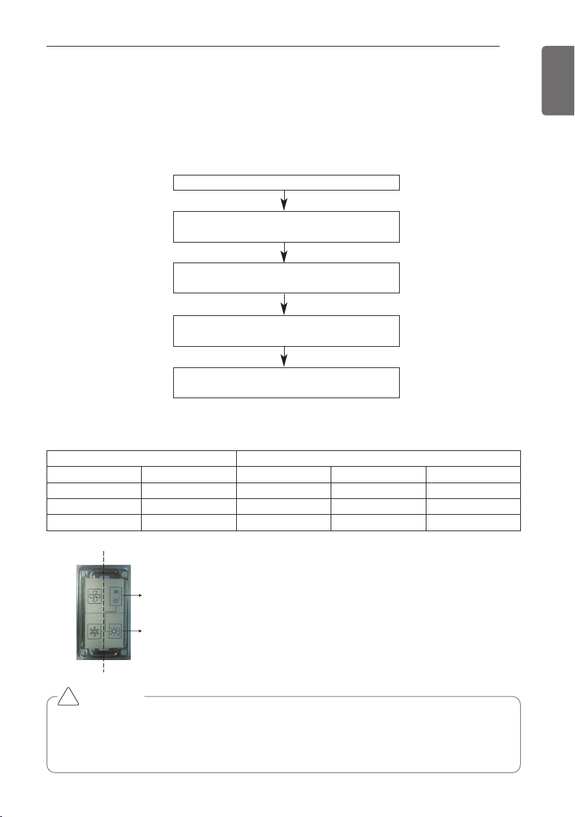
TEST RUN
95
ENGLISH
TEST RUN
Cool & Heat selector
mode setting method
Master unit PCB DIP switch on : No.5
Select the mode using ‘▶’, ‘◀’ Button :
“Func” Push the ‘●’ button
Select the Function using ‘▶’, ‘◀’ Button :
“Fn1” Push the ‘●’ button
Select the Option using ‘▶’, ‘◀’ Button :
“oFF”,“op1”,“op2” Push the ‘●’ button
Cool & Heat Selection mode is set
Function setting
Switch control Function
Switch(Phase) Switch(Bottom) oFF op1(mode) op2(mode)
Right Left Not operate Cooling Cooling
Right Right Not operate Heating Heating
Left - Not operate Fan mode Off
CAUTION
• Ask an authorized technician to setting a function.
• If do not use a function, set an off-mode.
• If use a function, first install a Cool & Heat selector.
!
Switch (Phase)
Switch (Bottom)
Left side
Right side
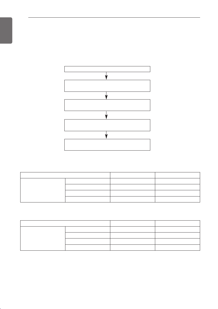
96
TEST RUN
ENGLISH
Static pressure compensation mode
This function secures the air flow rate of ODU, in case static pressure has been applied like using
duct at fan discharge of ODU.
Static pressure compensation mode setting method
FAN Maximum RPM of each step (460V Model)
Master unit PCB DIP switch on : No.5
Select the mode using ‘▶’, ‘◀’ Button :
“Func” Push the ‘●’ button
Select the Function using ‘▶’, ‘◀’ Button :
“Fn2” Push the ‘●’ button
Select the Option using ‘▶’, ‘◀’ Button :
“op1~op3” Push the ‘●’ button
Start the Static pressure compensation mode :
Save the selected option value in EEPROM
Capacity 8HP(6Ton)
10~14HP, 18HP(8~14Ton)
Max. RPM
Standard 730 950
op1 760 1020
op2 780 1050
op3 800 1130
FAN Maximum RPM of each step (220V Model)
Capacity 8HP(6Ton)
10~14HP, 18HP(8~14Ton)
Max. RPM
Standard 850 1050
op1 870 1080
op2 890 1110
op3 900 1120
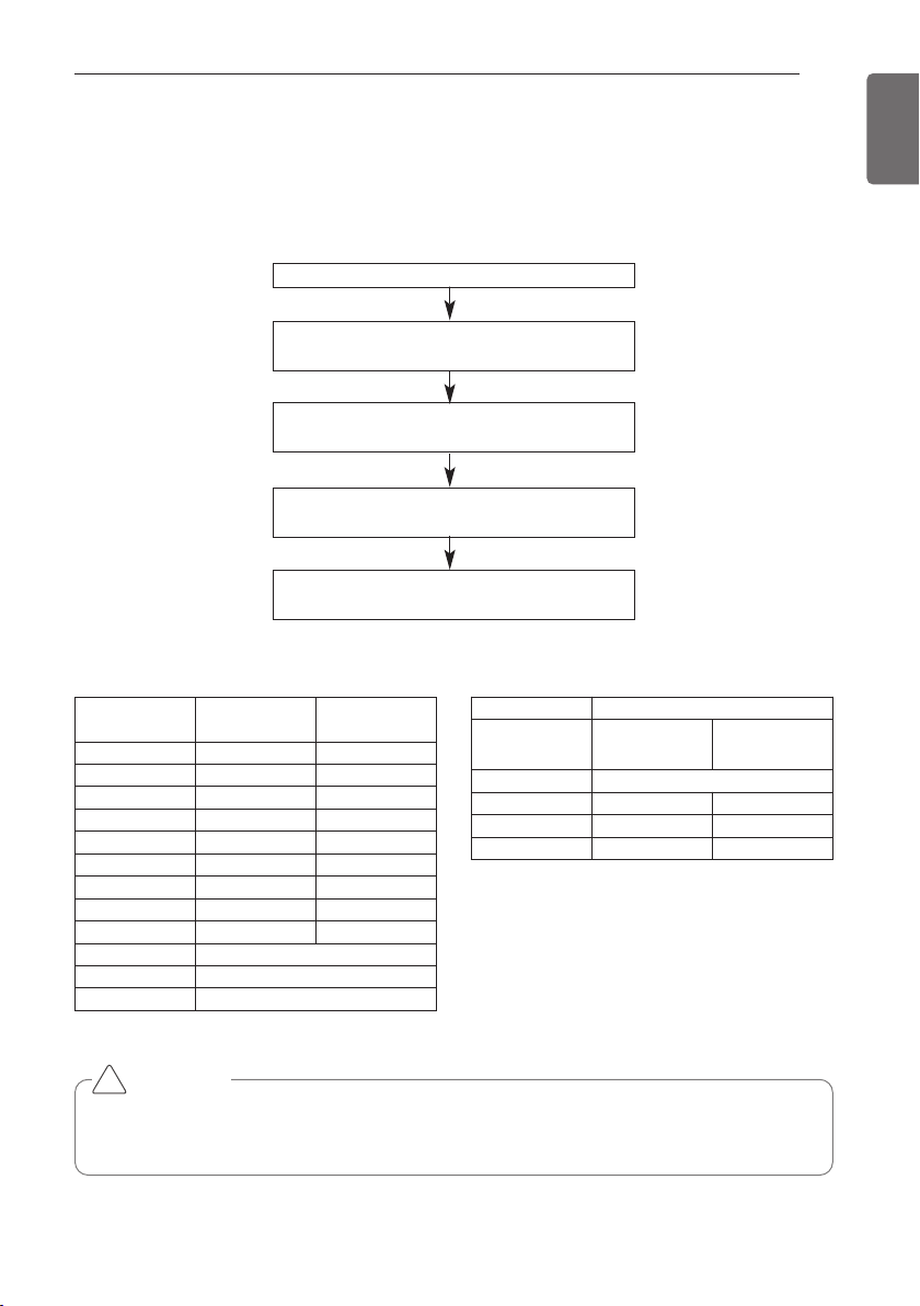
TEST RUN
97
ENGLISH
Night Low Noise Function
In cooling mode, this function makes the ODU fan operate at low RPM to reduce the fan noise of
ODU at night which has low cooling load.
Night low noise function setting method
Time Settings Noise
Master unit PCB DIP switch on : No.5
Select the mode using ‘▶’, ‘◀’ Button :
“Func” Push the ‘●’ button
Select the Function using ‘▶’, ‘◀’ Button :
“Fn3” Push the ‘●’ button
Select the Option using ‘▶’, ‘◀’ Button :
“op1~op12” Push the ‘●’ button
Start the Night low noise function :
Save the selected option value in EEPROM
Step
Judgment
Time(Hr)
Operation
Time(Hr)
op1 8 9
op2 6.5 10.5
op3 5 12
op4 8 9
op5 6.5 10.5
op6 5 12
op7 8 9
op8 6.5 10
op9 5 12
op10 Continuous operation
op11 Continuous operation
op12 Continuous operation
CAUTION
• Request installer to set the function during installation.
• If ODU RPM changes, cooling capacity may go down.
!
Capacity
Heat Pump 8HP(6Ton)
10~14HP, 18HP
(8~14Ton)
Step Noise(dB)
op1~op3, op10 55 59
op4~op6, op11 52 56
op7~op9, op12 49 53
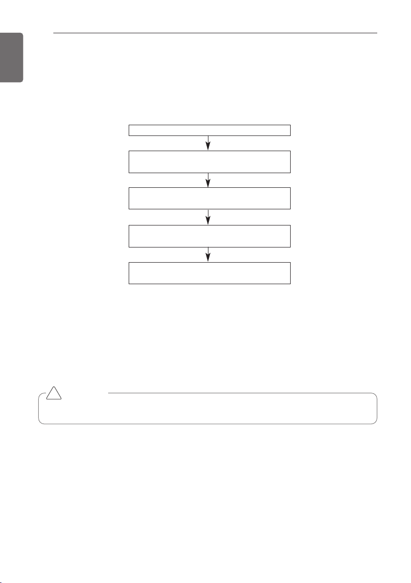
98
TEST RUN
ENGLISH
Overall defrost mode
mode setting method
Master unit PCB DIP switch on : No.5
Select the mode using ‘▶’, ‘◀’ Button :
“Func” Push the ‘●’ button
Select the Function using ‘▶’, ‘◀’ Button :
“Fn4” Push the ‘●’ button
Select the Option using ‘▶’, ‘◀’ Button :
“on” ~ “oFF” Push the ‘●’ button
Overall defrost mode is set
mode setting
CAUTION
• Ask an authorized technician to setting a function.
!
- on: Operate overall defrost
- off: Operate partial defrost
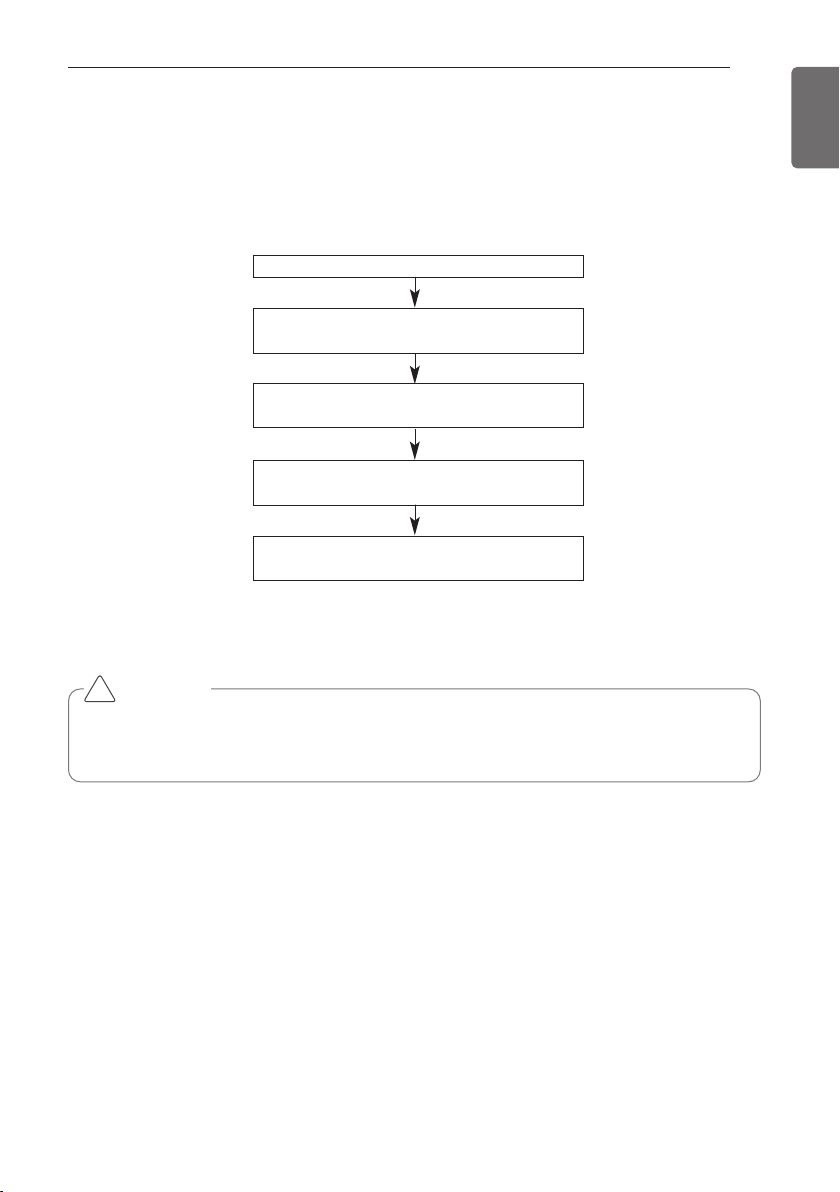
TEST RUN
99
ENGLISH
Setting the ODU address
mode setting method
Master unit PCB DIP switch on : No.5
Select the mode using ‘▶’, ‘◀’ Button :
“Func” Push the ‘●’ button
Select the Function using ‘▶’, ‘◀’ Button :
“Fn5” Push the ‘●’ button
Select the Option using ‘▶’, ‘◀’ Button :
“0” ~ “255” Push the ‘●’ button
ODU address is set
CAUTION
• Ask an authorized technician to setting a function.
• If use a function, first install a Central controller.
!
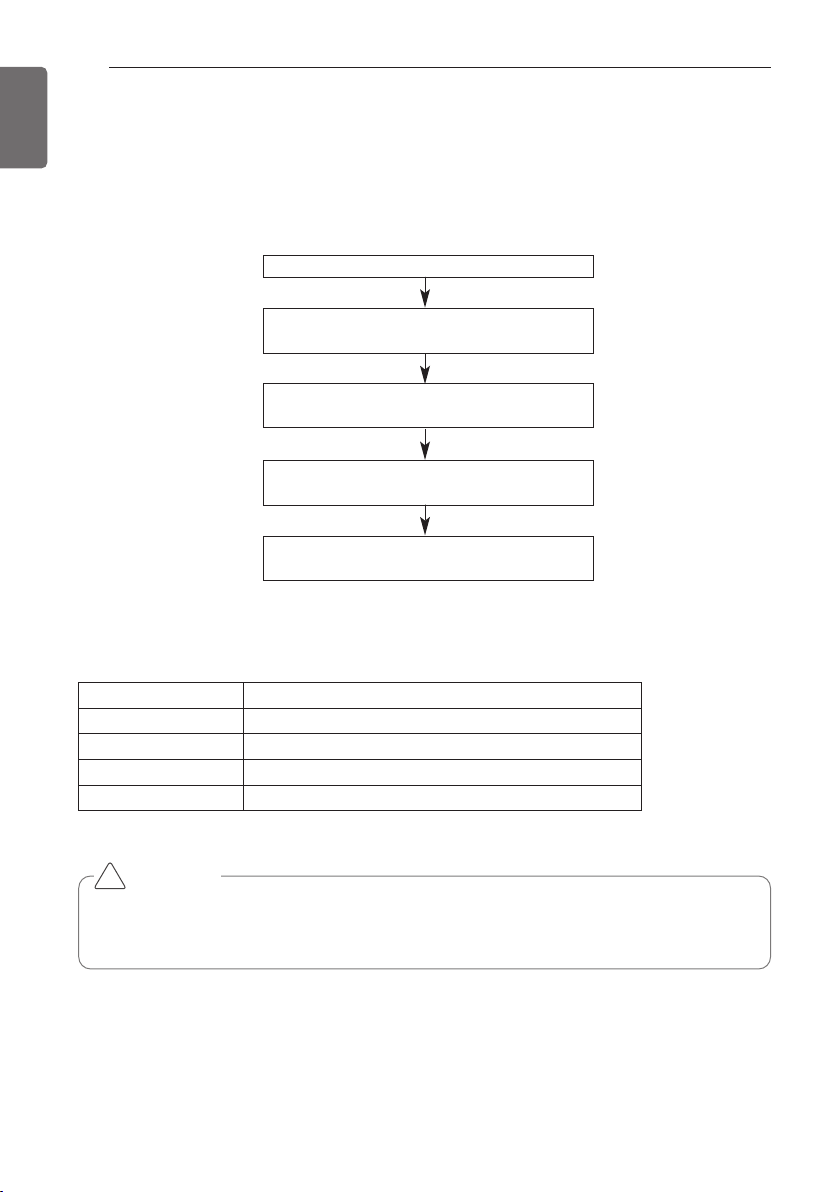
100
TEST RUN
ENGLISH
Snow removal & rapid defrost
mode setting method
Master unit PCB DIP switch on : No.5
Select the mode using ‘▶’, ‘◀’ Button :
“Func” Push the ‘●’ button
Select the Function using ‘▶’, ‘◀’ Button :
“Fn6” Push the ‘●’ button
Select the Option using ‘▶’, ‘◀’ Button :
“oFF”,“op1” ~ “op3” Push the ‘●’ button
Mode is set
CAUTION
• Ask an authorized technician to setting a function.
• If do not use a function, set an off-mode.
!
mode setting
setting Mode
oFF Not setting
op1 Snow removal mode
op2 Rapid defrost mode
op3 Snow removal mode. + Rapid defrost mode.
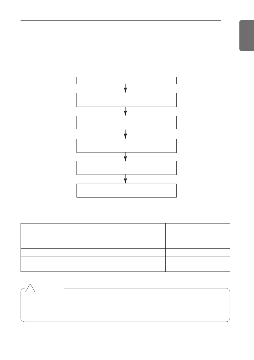
TEST RUN
101
ENGLISH
Target pressure adjusting
mode setting method
Master unit PCB DIP switch on : No.5
Select the mode using ‘▶’, ‘◀’ Button :
“Func” Push the ‘●’ button
Select the Option using ‘▶’, ‘◀’ Button :
“op1” ~ “op4” Push the ‘●’ button
Select the Function using ‘▶’, ‘◀’ Button :
“Fn8” Push the ‘●’ button
Target pressure is set
Select the Option using ‘▶’, ‘◀’ Button :
“HEAT” , “COOL” Push the ‘●’ button
CAUTION
• Ask an authorized technician to setting a function.
• If do not use a function, set an off-mode.
• Change a power consumption or capacity.
!
Setting
mode
Purpose
Condensing
temperature
variation
Evaporating
temperature
variation
“Heat” “Cool”
op1 Increase capacity Increase capacity
-3°C(26.6°F) +2°C(35.6°F)
op2
Decrease power consumption
Increase capacity
-1.5°C(29.3°F) -2°C(28.4°F)
op3
Decrease power consumption Decrease power consumption +2.5°C(36.5°F) -4°C(24.8°F)
op4
Decrease power consumption Decrease power consumption -4.5°C(23.9°F) -6°C(21.2°F)
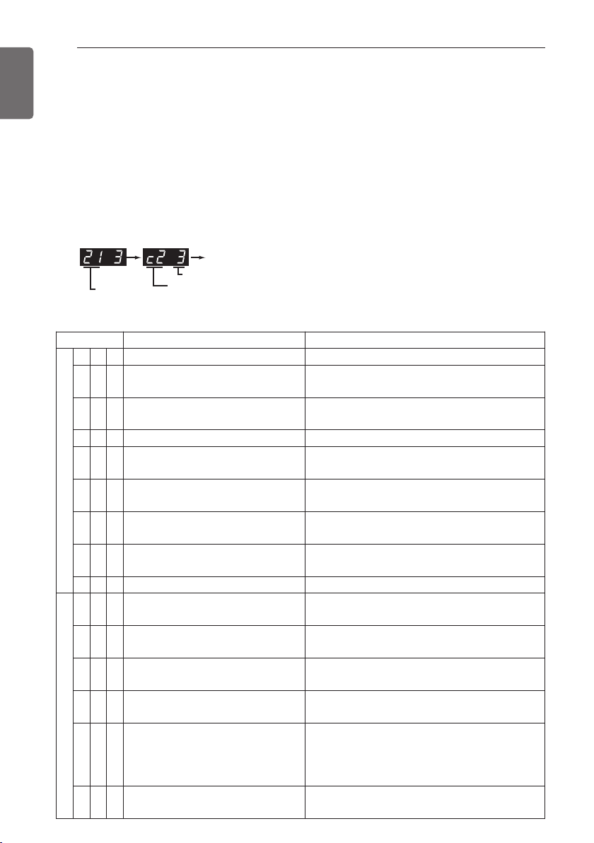
102
TEST RUN
ENGLISH
Self-Diagnosis Function
Error Indicator
- This function indicates types of failure in self-diagnosis and occurrence of failure for air condition.
- Error mark is displayed on display window of indoor units and wired remote controller, and 7-seg-
ment LED of outdoor unit control board as shown in the table.
- If more than two troubles occur simultaneously, lower number of error code is first displayed.
- After error occurrence, if error is released, error LED is also released simultaneously.
Error Display
1st,2nd,3rd LED of 7-segment indicates error number, 4th LED indicates unit number.
(* = 1:Master, 2:Slave 1, 3:Slave 2)
Ex)
* Refer to the DX-Venitilation manual for DX-Venitilation error code.
Display Title Cause of Error
Indoor unit related error
0 1 -
Air temperature sensor of indoor unit Air temperature sensor of indoor unit is open or short
0 2 -
Inlet pipe temperature sensor of indoor
unit
Inlet pipe temperature sensor of indoor unit is open or short
0 3 -
Communication error : wired remote
controller ÷ indoor unit
Failing to receive wired remote controller signal in indoor
unit PCB
0 4 -
Drain pump Malfunction of drain pump
0 5 -
Communication error : outdoor unit ÷
indoor unit
Failing to receive outdoor unit signal in indoor unit PCB
0 6 -
Outlet pipe temperature sensor of indoor
unit
Outlet pipe temperature sensor of indoor unit is open or
short
0 9 -
Indoor EEPROM Error
In case when the serial number marked on EEPROM of
Indoor unit is 0 or FFFFFF
1 0 -
Poor fan motor operation
Disconnecting the fan motor connector/Failure of indoor
fan motor lock
1 7 -
Inlet Air temperature sensor of FAU Air temperature sensor of indoor unit is open or short
Outdoor unit related error
2 1 *
Master Outdoor Unit Inverter Compressor
IPM Fault
Master Outdoor Unit Inverter Compressor Drive IPM Fault
2 2 *
Inverter Board Input Over Current(RMS) of
Master Outdoor Unit
Master Outdoor Unit Inverter Board Input Current excess
(RMS)
2 3 *
Master Outdoor Unit Inverter Com-
pressor DC link Low Voltage
DC charging is not performed at Master Outdoor
Unit after starting relay turn on.
2 4 *
Master Outdoor Unit High Pressure
Switch
System is turned off by Master Outdoor Unit
high pressure switch.
2 5 *
Master Outdoor Unit Input Voltage
High/ Low Voltage
Master Outdoor Unit input voltage is over 289V
or below 173V(ARUB***BTE4)
Master Outdoor Unit input voltage is over 506V
or below 414V(ARUB***DTE4)
2 6 *
Master Outdoor Unit Inverter Com-
pressor Start Failure
The First Start Failure by Master Outdoor Unit In-
verter Compressor Abnormality
Error No. of Compressor
Error No.
Error No. of Unit
Repeat
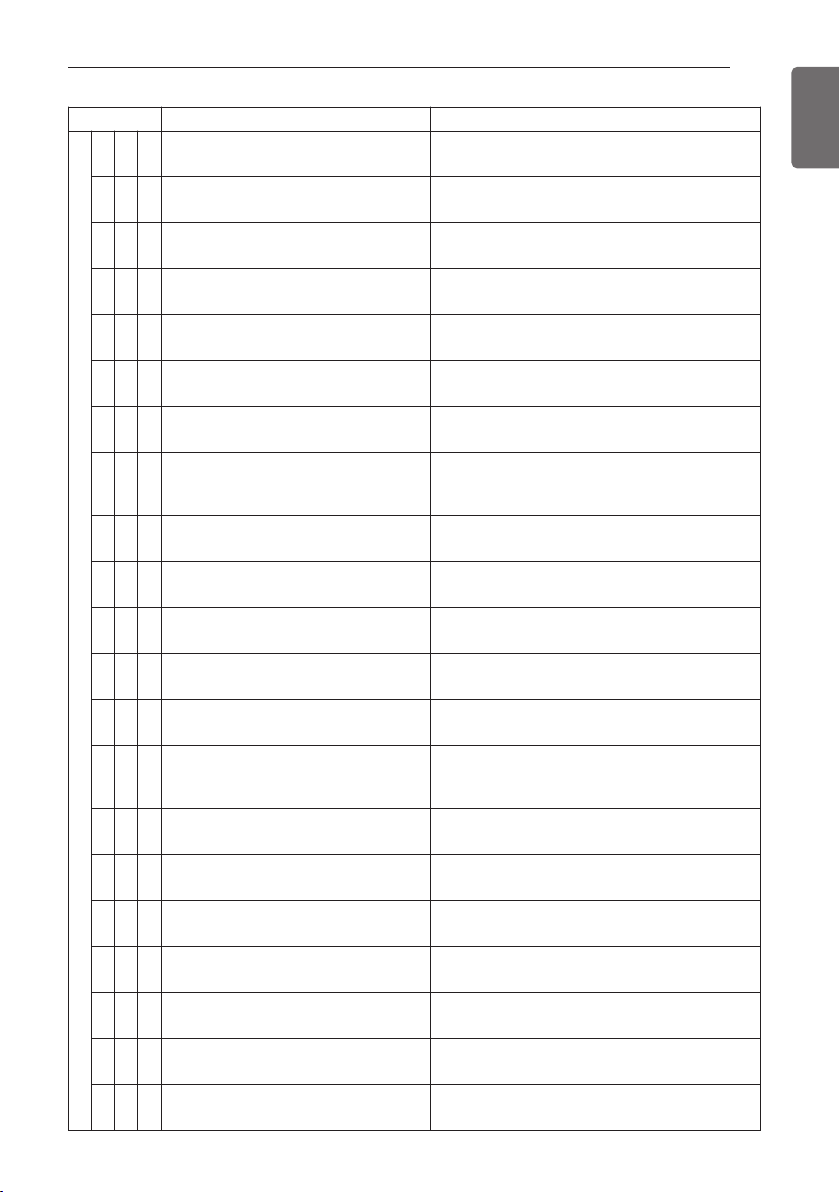
TEST RUN
103
ENGLISH
Display Title Cause of Error
Outdoor unit related error
2 9 *
Master Outdoor Unit Inverter Com-
pressor Over Current
Master Outdoor Unit Inverter Compressor Fault
or Drive Fault
3 2 *
Master Outdoor Unit Inverter Com-
pressor1 High Discharge Temperature
Master Outdoor Unit Inverter Compressor1
High Discharge Temperature
3 3 *
Master Outdoor Unit Inverter Com-
pressor2 High Discharge Temperature
Master Outdoor Unit Inverter Compressor2
High Discharge Temperature
3 4 *
High Pressure of Master Outdoor Unit High Pressure of Master Outdoor Unit
3 5 *
Low Pressure of Master Outdoor Unit Low Pressure of Master Outdoor Unit
3 6 *
Master Outdoor Unit Low Compres-
sion Ratio Limited
Master Outdoor Unit Low Compression Ratio
Limited
4 0 *
Master Outdoor Unit Inverter Com-
pressor CT Sensor Fault
Master Outdoor Unit Inverter Compressor CT
Sensor open or short
4 1 *
Master Outdoor Unit Inverter Com-
pressor1 Discharge Temperature Sen-
sor Fault
Master Outdoor Unit Inverter Compressor Dis-
charge Temperature Sensor open or short
4 2 *
Master Outdoor Unit Low Pressure
Sensor Fault
Master Outdoor Unit Low Pressure Sensor
open or short
4 3 *
Master Outdoor Unit High Pressure
Sensor Fault
Master Outdoor Unit High Pressure Sensor
open or short
4 4 *
Master Outdoor Unit Air Temperature
Sensor Fault
Master Outdoor Unit Air Temperature Sensor
open or short
4 5 *
Master Outdoor Unit Heat Exchanger
Temperature Sensor (Front side) Fault
Master Outdoor Unit Heat Exchanger Tempera-
ture Sensor(Front side) open or short
4 6 *
Master Outdoor Unit Suction Tempera-
ture Sensor Fault
Master Outdoor Unit Suction Temperature Sen-
sor open or short
4 7 *
Master Outdoor Unit Inverter Com-
pressor2 Discharge Temperature Sen-
sor Fault
Master Outdoor Unit Inverter Compressor2 Dis-
charge Temperature Sensor open or short
4 9 *
Master Outdoor Unit Faulty IPM Tem-
perature Sensor
Master Outdoor Unit IPM Temperature Sensor
short/open
5 0 *
Omitting connection of R, S, T power
of Master Outdoor Unit
Omitting connection of Master outdoor unit
5 1 *
Excessive capacity of indoor units
Excessive connection of indoor units compared
to capacity of Outdoor Unit
5 2 *
Communication error : inverter PCB ’
Main PCB
Failing to receive inverter signal at main PCB of
Master Outdoor Unit
5 3 *
Communication error : indoor unit ’
Main PCB of Outdoor Unit
Failing to receive indoor unit signal at main PCB
of Outdoor Unit .
5 7 *
Communication error : Main PCB ’
inverter PCB
Failing to receive signal main PCB at inverter
PCB of Master Outdoor Unit
5 9 *
Mixing Installation of Sub Outdoor Unit
Mixing Installation of Old Sub Outdoor Unit and
New Slave Outdoor Unit
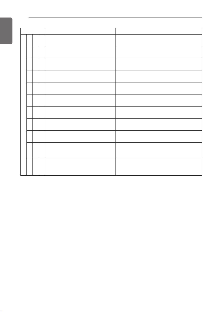
104
TEST RUN
ENGLISH
Display Title Cause of Error
Outdoor unit related error
6 0 *
Inverter PCB EEPROM Error of Master
Outdoor Unit
Access Error of Inverter PCB of Master Outdoor
Unit
6 2 *
Master Outdoor Unit Inverter Heatsink
High Temperature
System is turned off by Master Outdoor Unit In-
verter Heatsink High Temperature
6 5 *
Master Outdoor Unit Inverter Heatsink
Temperature Sensor Fault
Master Outdoor Unit Inverter Heatsink Temper-
ature Sensor open or short
6 7 *
Master Outdoor Unit Fan Lock Restriction of Master Outdoor Unit
7 1 *
Converter CT Sensor Error of Master
Outdoor Unit
Converter CT Sensor open or short of Master
Outdoor Unit
7 5 *
Master Outdoor Unit Fan CT Sensor
Error
Master Outdoor Unit Fan CT Sensor open or
short
7 6 *
Master Outdoor Unit Fan DC Link High
Voltage Error
Master Outdoor Unit Fan DC Link High Voltage
Error
7 7 *
Master Outdoor Unit Fan Over Current
Error
Master Outdoor Unit Fan Current is over 5A
7 9 *
Master Outdoor Unit Fan Start Failure
Error
Master Outdoor Unit Fan First Position Sensing
Failure
8 6 *
Master Outdoor Unit Main PCB EEP-
ROM Error
Communication Fail Between Master Outdoor
Unit Main MICOM and EEPROM or omitting
EEPROM
8 7 *
Master Outdoor Unit Fan PCB EEP-
ROM Error
Communication Fail Between Master Outdoor
Unit Fan MICOM and EEPROM or omitting
EEPROM
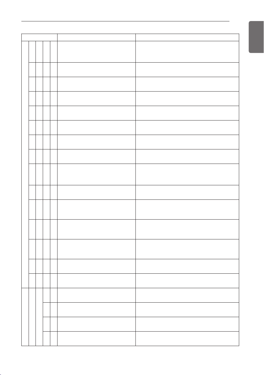
TEST RUN
105
ENGLISH
Display Title Cause of Error
1 0 4 *
Communication Error Between
Master Outdoor Unit and Other
Outdoor Unit
Failing to receive Slave Unit signal at main PCB
of Master Outdoor Unit
1
0
5
*
Master Outdoor Unit Fan PCB
Communication Error
Failing to receive fan signal at main PCB of
Master unit.
1 0
6
*
Master Outdoor Unit FAN IPM
Fault Error
Instant Over Current at Master Outdoor Unit
Fan IPM
1
0
7
*
Master Outdoor Unit Fan DC Link
Low Voltage Error
Master Outdoor Unit Fan DC Link Input Voltage
is under 380V
1 1 3
*
Master Outdoor Unit Liquid pipe
Temperature Sensor Error
Liquid pipe temperature sensor of Master Out-
door Unit is open or short
1 1 4
*
Master Outdoor Unit Subcooling
Inlet Temperature Sensor Error
Master Outdoor Unit Subcooling Inlet Tempera-
ture Sensor Error
1 1 5
*
Master Outdoor Unit Subcooling
Outlet Temperature Sensor Error
Master Outdoor Unit Subcooling Outlet Tem-
perature Sensor Error
1 1 6
*
Master Outdoor Unit Oil Level Sen-
sor Error
Oil Level Sensor of Master Outdoor Unit is
open or short
1 4 5 *
Master outdoor unit Main Board -
External Board communication
Error
Master outdoor unit Main Board - External
Board communication Error
1
5
1
*
Failure of operation mode conver-
sion at Master Outdoor Unit
Failure of operation mode conversion at Master
Outdoor Unit
1 5
3
*
Master Outdoor Unit Heat Exchanger
Temperature Sensor (upper part)
Fault
Master Outdoor Unit Heat Exchanger Tempera-
ture Sensor (upper part) Fault
1
5
4
*
Master Outdoor Unit Heat Exchanger
Temperature Sensor (lower part)
Fault
Master Outdoor Unit Heat Exchanger Tempera-
ture Sensor(lower part) open or short
1 8 2
*
Master outdoor unit External Board
Main-Sub Micom communication
Error
Master Outdoor Unit Main Board Main-Sub
Micom communication failed
1 9 3
*
Master Outdoor Unit Fan Heatsink
High Temperature
System is turned off by Master Outdoor Unit
Fan Heatsink High Temperature
1 9 4
*
Master Outdoor Unit Fan Heatsink
Temperature Sensor Fault
Master Outdoor Unit Fan Heatsink Temperature
Sensor open or short
HR unit related error
2 0
0
1
Searching pipe Error Failure of automatic addressing of valves
1
C +
#HR
HR unit1 Liqiud sensor error Liquid pipe sensor of HR unit open or short
2
C +
#HR
HR unit1 Sub Cooling Pipe In sen-
sor error
Sub Cooling Pipe In sensor of HR unit open or
short
3
C +
#HR
HR unit1 Sub Cooling Pipe Out sen-
sor error
Sub Cooling Pipe Out sensor of HR unit. open
or short
Outdoor unit related error
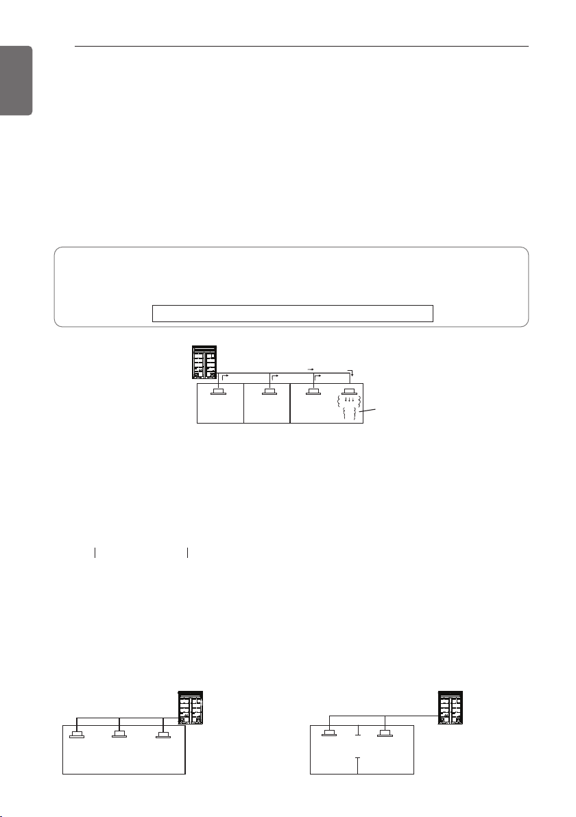
106
CAUTION FOR REFRIGERANT LEAK
ENGLISH
Checking procedure of limiting concentration
Check limiting concentration along following steps and take appropriate measure depending on
the situation.
Calculate amount of all the replenished refrigerant [kg(lbs)] per each refrigerant system.
Calculate minimum room capacity
Calculate room capacity by regarding a portion as one room or the smaller room.
- Without partition - With partition and with opening which serve
as passage of air to adjoining room
Limiting concentration is the limit of Freon gas concentration where immediate measures can
be taken without hurting human body when refrigerant leaks in the air. The limiting concen-
tration shall be described in the unit of Kg/m
3
(lbs/ft
3
) (Freon gas weight per unit air volume)
for facilitating calculation.
Limiting concentration: 0.44kg/m
3
(0.028lbs/ft
3
)(R410A)
Amount of additional
replenished refrigerant
Total amount of replenished
refrigerant in refrigerant
facility [kg(lbs)]
+
=
Note : In case one refrigerant facility is
divided into 2 or more refrigerant
systems and each system is
independent, amount of replenished
refrigerant of each system shall be
adopted.
Amount of replenished
refrigerant per one outdoor
unit system
Amount of replenished
refrigerant at factory shipment
Amount of additionally
replenished refrigerant
depending on piping
length or piping
diameter at customer
Outdoor unit
Indoor unit
Outdoor unit
Indoor unit
Opening
Partition
In the case of opening
without door , or 0.15
% or more openings
(to floor space) both
above and below door)
Outdoor unit
(No.1 system)
Flow of
refrigerant
Indoor unit
Room where refrigerant leaks
(Refrigerant of the whole No.1
system flows out.)
The installer and system specialist shall secure safety against leakage according to local regula-
tions or standards.
The following standards may be applicable if local regulations are not available.
Introduction
Though the R410A refrigerant is harmless and incombustible itself , the room to equip the air
conditioner should be large to such an extent that the refrigerant gas will not exceed the limiting
concentration even if the refrigerant gas leaks in the room.
Limiting concentration
CAUTION FOR REFRIGERANT LEAK
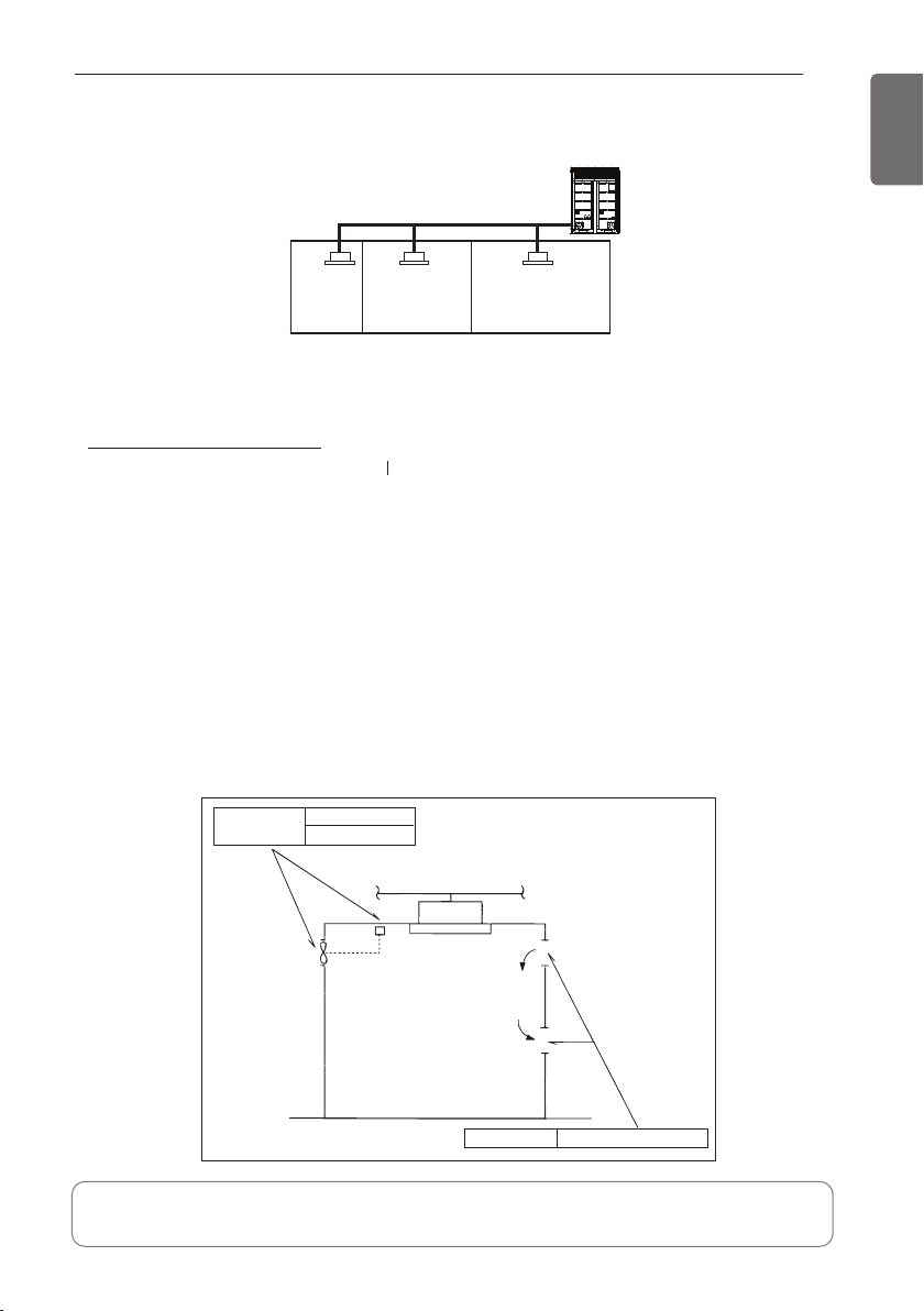
CAUTION FOR REFRIGERANT LEAK
107
ENGLISH
- With partition and without opening which serve as passage of air to adjoining room
Calculate refrigerant concentration
In case the concentration exceeds the limit
When the concentration exceeds the limit, change original plan or take one of the countermea-
sures shown below:
• Countermeasure 1
Provide opening for ventilation.
Provide 0.15% or more opening to floor space both above and below door, or provide opening
without door.
• Countermeasure 2
Provide gas leak alarm linked with mechanical ventilator.
Reducing the outdoor refrigerant qty.
(R410A)
=
Refrigerant concentration
[Kg/m
3
(lbs/ft
3
)]
Total amount of replenished
refrigerant in refrigerant facility [kg(lbs)]
Capacity of smallest room where
indoor unit is installed [m
3
(ft
3
)]
In case the result of calculation exceeds
the limiting concentration, perform the
same calculations by shifting to the
second smallest, and the third smallest
rooms until at last the result is below the
limiting concentration.
Outdoor unit
Indoor unit
Smallest
room
Countermeasure 2
Gas leak alarm
Mechanical ventilator
Countermeasure 1
Opening effective to ventilation
Indoor unit
Pay a special attention to the place, such as a basement, etc. where refrigerant can stay,
since refrigerant is heavier than air.
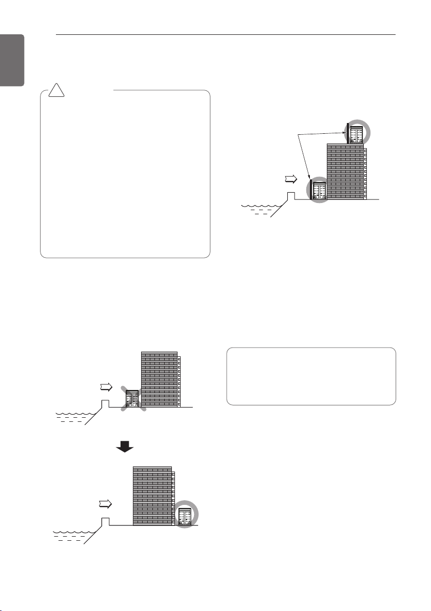
108
INSTALLATION GUIDE AT THE SEASIDE
ENGLISH
Selecting the location(Outdoor Unit)
If the outdoor unit is to be installed close to
the seaside, direct exposure to the sea wind
should be avoided. Install the outdoor unit on
the opposite side of the sea wind direction.
In case, to install the outdoor unit on the sea-
side, set up a windbreak not to be exposed to
the sea wind.
- It should be strong enough like concrete to
prevent the sea wind from the sea.
- The height and width should be more than
150% of the outdoor unit.
- It should be keep more than 70cm(2.3ft) of
space between outdoor unit and the wind-
break for easy air flow.
Select a well-drained place.
CAUTION
• Air conditioners should not be installed
in areas where corrosive gases, such as
acid or alkaline gas, are produced.
• Do not install the product where it could
be exposed to sea wind (salty wind) di-
rectly. It can result corrosion on the
product. Corrosion, particularly on the
condenser and evaporator fins, could
cause product malfunction or inefficient
performance.
• If outdoor unit is installed close to the
seaside, it should avoid direct exposure
to the sea wind. Otherwise it needs ad-
ditional anticorrosion treatment on the
heat exchanger.
Sea wind
Sea wind
Sea wind
Windbreak
• Periodic ( more than once/year ) clean-
ing of the dust or salt particles stuck on
the heat exchanger by using water
INSTALLATION GUIDE AT THE SEASIDE
!
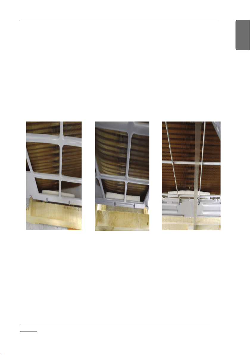
OUTDOOR UNIT (ODU) INSTALLATION DETAILS FOR (3) FOAM SCREW PROTECTOR PADS.
109
ENGLISH
Place (1) foam pad at the bottom of the unit between the casing and the coil in each of the fol-
lowing locations:
• Right side (toward front side of ODU) and securely in place to protect the heat exchanger coil
from the sharp screw points.
• Left side (toward front side of ODU) and securely in place to protect the heat exchanger coil
from the sharp screw points.
• Back side (center of ODU) and securely in place to protect the heat exchanger coil from the
sharp screw points. Note: take caution as screw locations are not easily visible.
Important:
The (3) pads must be securely in place to protect the heat exchanger coil from the sharp screw
points during a seismic event.
Use OSHPD Seismic Certification Preapproval (OSP)
• (1) OSP Label for ODU > OSP-0386-10 for LG Model No.: ARU*nnn*TE4
• (3) foam screw protector pads w/ adhesive backing
• This installation detail
Please do not discard this kit before following this instruction during the installation of the
ODU(s).
OUTDOOR UNIT (ODU) INSTALLATION DETAILS
FOR (3) FOAM SCREW PROTECTOR PADS.
Right Left Back

110
ENGLISH