Loading ...
Loading ...
Loading ...
5
Electrical connection
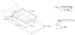
The connection of the hobs to mains is effected via the flex and the three pin plug located underneath the
hotplate. The appliance operate at a main voltage of 120V a.c., frequency 60Hz. Electric power absorption is
about 1W for 5 gas burner version or 2W for 6 gas burners version.
WARNING: Electrical Grounding Instructions: This appliance is equipped with a (three-prong)
grounding plug for your protection against shock hazard and should be plugged directly into a
properly grounded receptable. Do not cut or remove the grounding prong from this plug.
Wiring diagrams Wiring diagram description
see Fig. 12. 1. Cable terminal
2. Ignition switch
3. Spark generator
4. Ignition spark
L. Black
N. White
T. Green (earth)
Room ventilation – Location and venting.
ATTENTION: An exhaust fan may be used with the appliance; in each case it shall be installed in
conformity with the national standards in force.
ATTENTION: Exhaust hood operation may affect other vented appliances; in each case it shall be
installed in conformity with the national standards in force.
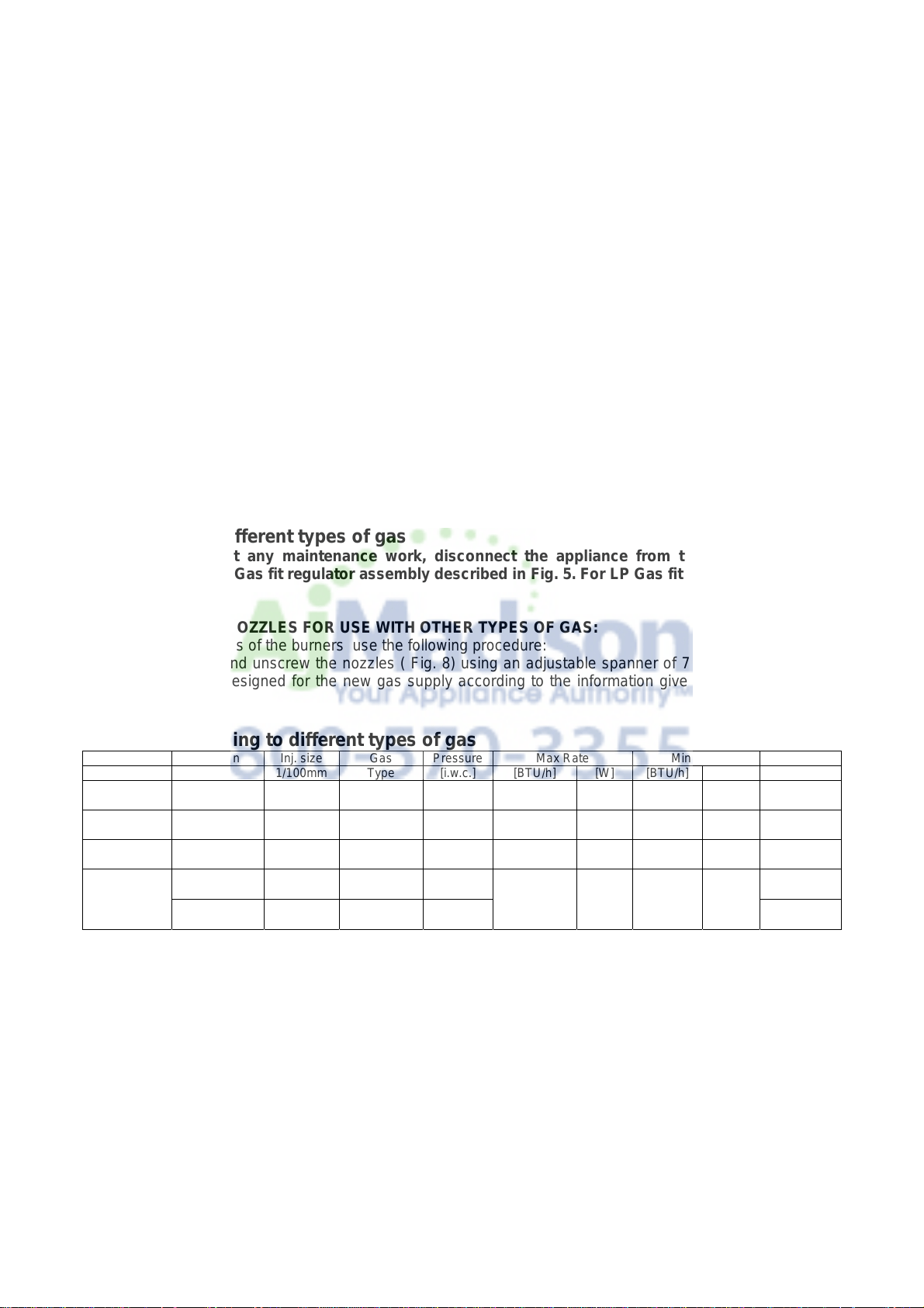
Conversion to different types of gas
Before carrying out any maintenance work, disconnect the appliance from the gas and electric
supply. For Natural Gas fit regulator assembly described in Fig. 5. For LP Gas fit assembly described
in fig. 5.
- CHANGING THE NOZZLES FOR USE WITH OTHER TYPES OF GAS:
To change the nozzles of the burners use the following procedure:
Lift up the burners and unscrew the nozzles ( Fig. 8) using an adjustable spanner of 7 mm and change the
nozzles with those designed for the new gas supply according to the information given in TABLE A shown
below.
TABLE A: Adapting to different types of gas
Burner Position Inj. size Gas Pressure Max Rate Min Rate By-pass size
1/100mm Type [i.w.c.] [BTU/h] [W] [BTU/h] [W] [1/100mm]
Auxiliary Front R 92 NG 4” 3750 1098 900 264 Regulated
56 LP(Propane) 11” 3750 1098 900 264 29
Semi-Rapid Rear L 117 NG 4” 6000 1759 1500 439 Regulated
73 LP(Propane) 11” 6300 1845 1500 439 36
Rapid Rear R 155 NG 4” 10400 2046 2500 732 Regulated
98 LP(Propane) 11” 11400 3339 2500 732 47
Front L Inner 80 NG 4”
900 264
Regulated
Dual 50 LP(Propane) 11” NG 17000 4980 29
burner Front L Outer N°2 x 130 NG 4” LP 18800 5507 Regulated
N°2 x 83 LP(Propane) 11” 65
CAUTION: save the orifices removed from the appliance for future use
Regulation of burners
Regulation of the "MINIMUM" on the burners
To regulate the minimum on the burners carry out the following procedure indicated below:
1) Turn on the burner and put the knob onto position MINIMUM ( small flame ).
2) Remove the knob ( Fig. 9) of the tap which is set for standard pressure. The knob is found on the bar of
the tap itself.
3) Beside the tap bar on the work top, use a small screwdriver that fits the screw (gold) found on the lower
part of the tap (auxiliary, semirapid, rapid Fig. 9) (dual fig.10) and turn the fixing screw to the right or left until
the flame of the burner is regulated in the most suitable way to MINIMUM.
4) Make sure that that the flame does not go out when changing the position quickly from MAXIMUM to the
MINIMUM position.
ATTENTION: The regulation described above can be carried out only with burners using natural gas,
while with burners using propane gas the screw must be fully screwed in, in a clockwise direction.
Loading ...
Loading ...
Loading ...