
Loading ...
TOOLS YOU WILL NEED
2
Installation Instructions
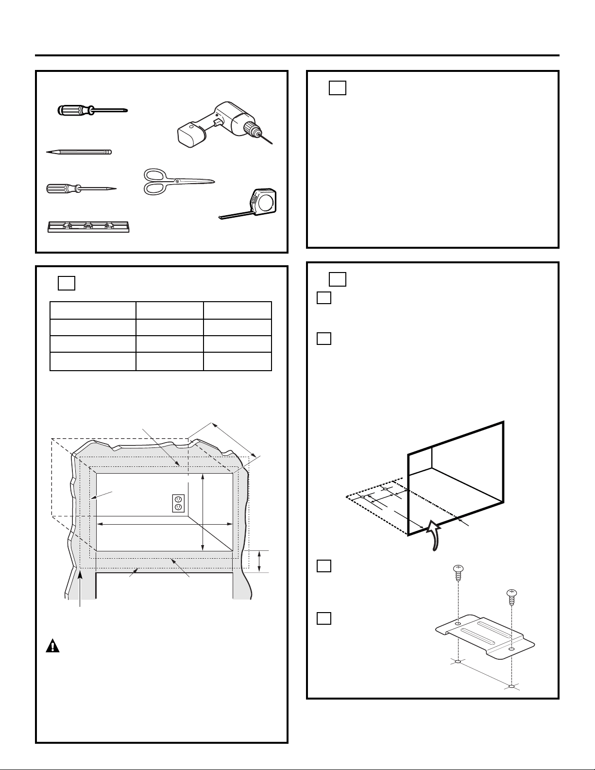
❒ #2 Phillips Screwdriver
❒ Tape Measure
❒ Drill with 7/64″ Bit or #35
❒ Scissors (Optional)
❒ Pencil
❒ Awl or Punch
❒
CUTOUT DIMENSIONS
WARNING — This trim kit uses air flow
from the top, bottom and sides of the trim frame.
Blocking the air flow can cause the microwave to
function improperly and may cause damage to
the microwave.
Allow a 1″ clearance beyond the edge of the trim
frame to provide proper air flow.
1
Depth
Height
1
1
⁄2″ Overlap
Width
1
1
⁄2″ Overlap
1″ Clearance beyond
trim frame
(on all sides)
3″ Min.
27″ Models: 1
1
⁄2″ overlap
30″ Models: 3″ overlap
❒
CUTOUT DIMENSIONS (CONT.)
On 27″ models, allow 1
1
⁄2″ on all sides for overlap
of the trim frame over the edges of the cutout.
On 30″ models, allow 1
1
⁄2″ at the top and bottom
and 3″ on each side for overlap of the trim frame
over the edges of the cutout.
FOR INSTALLATION ABOVE A BUILT-IN OVEN:
Microwave oven should be installed on a 3/8″
plywood base and supported by 2x4 or 1x2
equivalent runners on all sides. Base must be capable
of supporting a minimum of 100 lbs (45.3 kg).
1
* Min. depth with 120V–60 Hertz grounded power
receptacle outside cabinet 21
1
⁄2″
Min. depth with 120V–60 Hertz grounded power
receptacle inside cabinet 23″
Models 27″ 30″
Height 18
3
⁄4″ 18
3
⁄4″
Width 24″ ±
1
⁄16″ 24″ ±
1
⁄16″
Depth (min.)* 21
1
⁄2″ or 23″ 21
1
⁄2″ or 23″
❒
INSTALL THE ANTI-TIP BRACE
Draw a line on the cutout floor at the center of
the cutout, and extend the line 1/2″ down the
face of the cabinet.
Fold or cut the front edge of the template,
along the front guide line. Place the template
flush along the front edge of the cutout floor,
aligning the center line of the template with the
center line of the cutout floor. Mark the centers
of the two screw holes with an awl or center
punch for the anti-tip brace location as shown.
Remove the
template and drill
two holes for the
anti-tip brace.
Install the anti-tip
brace onto the
cutout floor using
two round-head
screws.
D
C
B
A
2
Round-Head
Screws
Anti-Tip
Brace
Cutout
Floor
Center
Line
B
A
C
DIMENSIONS:
A =
13
⁄16″
B = 3″
C = 20
1
⁄16″
❒ Level
Bottom of trim kit must be
minimum of 36″ from floor
1′ = 0.3 m
1″ = 2.5 cm
Loading ...
Loading ...
Loading ...