
Loading ...
Loading ...
Loading ...
7
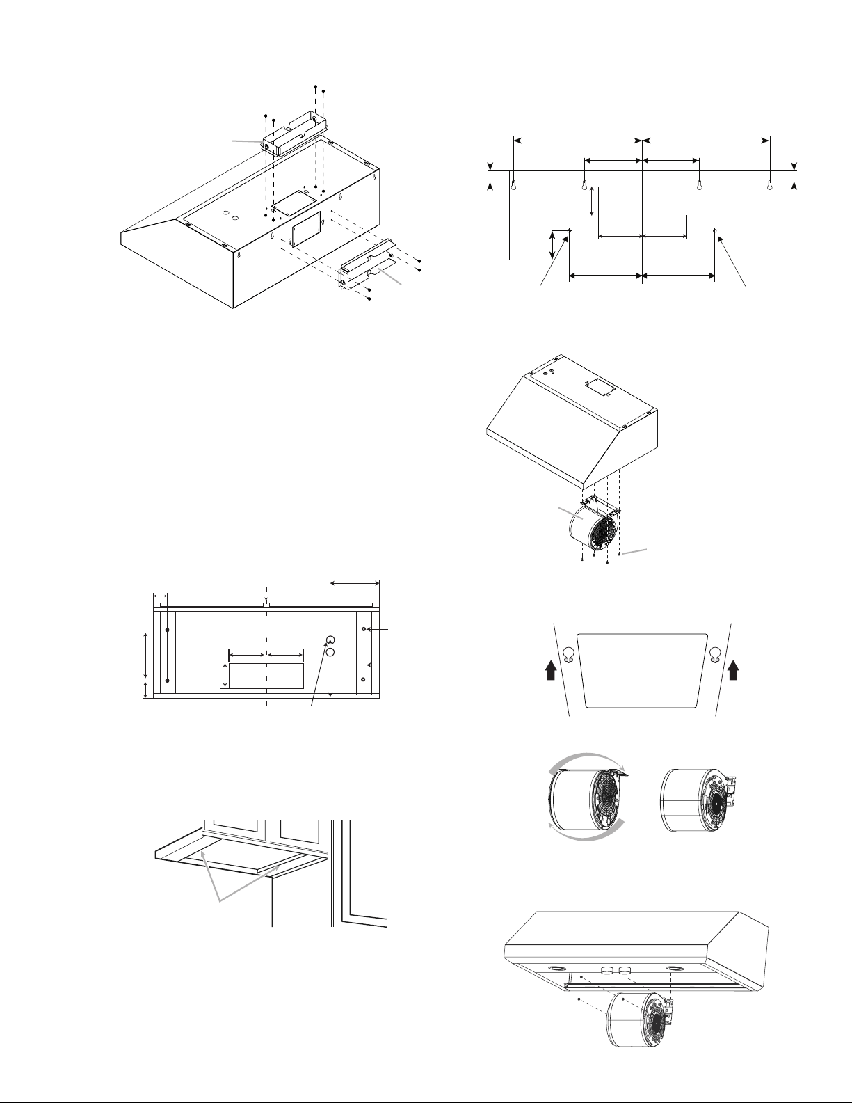
• Attach air exhaust transition over knockout opening with
4 - 4x8 mm screws.
A
A
NOTE:
The exhaust adaptor/damper can be installed up to 1 inch on
either side of the hood center to accommodate ocenter duct-
work. In extreme ocenter installations, one end of the duct
connector may need to be trimmed to clear the electrical cable
clamp.
Mark holes
Select the vent option that your installation will require and
proceed to that section:
Outside top exhaust
(Vertical duct– 3
1
⁄4”x 10” Rectangular)
Use the diagram or the hood as a template and mark the loca-
tions on the cabinet for ductwork, electrical wiring and keyhole
screw slots. It is recommended to make the marks before the
cabinet’s installation.
Wiring access knockout
(cabinet bottom side)
Mounting
screws (4)
Cabinet
front side
2
3
⁄4” (7 cm)
Vent
system hole
5
1
⁄2”
(14 cm)
4
31
⁄64”
(11 cm)
6
1
⁄16”
(15.4 cm)
7
1
⁄2”
(19 cm)
2
23
⁄64”
(6 cm)
13
⁄32”
(1 cm)
Vent
shims
CENTER
LINE
Cabinet
bottom side
5
1
⁄2”
(14 cm)
For recessed bottom cabinet only
If the cabinets have front, side or back trim, make 2 wood shims
the width of the trim and attach them to the cabinet bottom
recess on both sides.
Wood shims
Outside rear exhaust
(Horizontal duct– 3
1
⁄4”x 10” Rectangular)
Use the diagram or the hood as a template and mark the
locations on the wall for ductwork, electrical wiring and keyhole
screw slots.
CENTER LINE
Permanent
Mounting hole
2
61
⁄64”
(7.5 cm)
10
5
⁄8” (27 cm)
6
13
⁄16”(17.4 cm)
30”: 13
37
⁄64” (34.5 cm)
36”: 16
11
⁄16” (42,4 cm)
30”: 13
37
⁄64” (34.5 cm)
36”: 16
11
⁄16” (42,4 cm)
6
13
⁄16”(17.4 cm)
10
5
⁄8” (27 cm)
39
⁄64” (1.5 cm)
39
⁄64” (1.5 cm)
WALL
Permanent
Mounting hole
4
21
⁄64”
(11 cm)
5
1
⁄2”
(14 cm)
5
1
⁄2”
(14 cm)
1 Remove the grease filters.
2 Remove the blower mounting screws. Put the screws in a
safe place in order to use them again.
B
A
A. Blower
B. Blower screws
3 Set free the two blower springs from the top of the range
hood housing.
4 Flip the blower base to the rear face of the range hood.
5 Insert the two blower springs to the top of the range hood
housing, secure it with the four mounting screws previously
released.
Loading ...
Loading ...
Loading ...