
www.lg.com
Please read this installation manual completely before installing the product.
Installation work must be performed in accordance with the national wiring
standards by authorized personnel only.
Please retain this installation manual for future reference after reading it
thoroughly.
Multi Type
INSTALLATION MANUAL
AIR
CONDITIONER
P/NO : MFL67206502
http://www.lghvac.com
ENGLISH FRANÇAIS ESPAÑOL
FLEX MULTI SPLIT INSTALLATION
INSTRUCTIONS

Installation Manual 3
Multi Air Conditioner Installation Manual
TABLE OF CONTENTS
Installation Parts Provided ...................................................4
Product Introduction .............................................................5
Indoor Unit.........................................................................5
Outdoor Unit ......................................................................5
Safety Precautions ................................................................6
Installation of Indoor, Outdoor Unit .....................................9
Select the best location ....................................................9
Seaside Applications and Installation ..............................11
Piping length and elevation .............................................12
Installation............................................................................14
Connecting the piping......................................................14
How To Fix.......................................................................18
Wiring Connection ...........................................................19
Conduit connection..........................................................19
Ceiling dimension and hanging bolt location ...................20
How to Fix .......................................................................21
Wiring Connection ...........................................................21
Conduit connection..........................................................21
Installation of wired Remote Controller ...........................23
Wired remote controller switch information .....................24
Trial Operation.................................................................25
Celsius/Fahrenheit Switching ..........................................26
Setting the Central-Control Address................................27
ESP Function ..................................................................28
Ceiling dimension and hanging bolt location ...................29
Wiring Connection ...........................................................30
Conduit connection..........................................................30
Installation of Wired Remote Controller(Optional)...........31
Installation of Decorative Panel.......................................33
Drain Piping.....................................................................35
Flaring Work and Connection of Piping ............................38
Flaring work.....................................................................38
Connection of piping - Outdoor .......................................39
Installation .......................................................................42
Installation of The Main Unit............................................43
Connecting the Cable between Indoor Unit, Distributor
Unit and Outdoor Unit .........................................................44
Connect the cable to the Indoor unit. ..............................44
Connect the cable to the Distributor unit .........................45
Connect the cable to the Outdoor unit.............................46
Connection method of the connecting cable(Example)...48
Checking the Drainage, Insulating the Pipe and Special
Piping Applications .............................................................50
Checking the drainage ....................................................50
Insulating the Pipe and Special Piping Applications........50
Long Pipe Setting ................................................................51
Air Purging and Evacuation................................................52
Leak Checking.................................................................52
Evacuation.......................................................................53
Charging ...............................................................................54
Max Combination Capacity.................................................56
o Level gauge
o Screw driver
o Electric drill
o Hole core drill (ø50mm)
o Flaring tool set
o Specified torque wrenches
1.8kg.m, 4.2kg.m, 5.5kg.m, 6.6kg.m
(different depending on model No.)
o Adjustable wrench
o A glass of water
o Screw driver
o Hexagonal wrench(4mm)
o Refrigerant Gas Leak Detector
o Vacuum pump
o Gauge manifold
o Owner's manual
o Thermometer
o Remote Control Holder
Installation Requirements
Required Tools
ENGLISH
4 Multi Air Conditioner
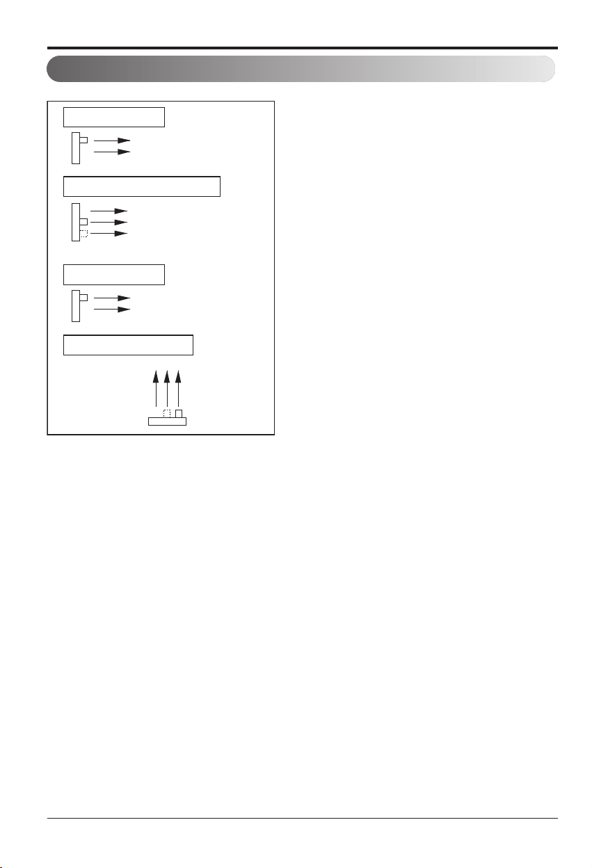
Installation Parts Provided
Installation Parts Provided
[Standard / Standard Libero / Artcool Mirror]
[Ceiling Concealed Duct Type]
[Ceiling Cassette Type]
Type "A" screw Type "A" screw
Type "B" screw Type "B" screw
Remote control holderRemote control holder
Type 1 Type 2
Installation plate Installation plate
Type “A” screw Type “A” screw
Type "B" screw
Type "C" screw
Type "B" screw
Type "C" screw
Type "B" screw
Type "C" screw
Remote control holderRemote control holder
Type 3 Type 4
Installation plate Installation plate
Type 5
Installation plate
Name
Quantity
Shape
for gas pipe
for liquid pipe
Clamp metal
1 EA
Insulation for
fitting
1 set
Clamp
8 EA
Screws for
duct flanges
1 set
Conduit Bracket
Screw(M4) 2EA
Conduit
Bracket
1 EA
Name
Quantity
Shape
for gas pipe
Conduit Bracket
Screw(M4) 2EA
for liquid pipe
Clamp metal
1 EA
Insulation for Remote
control holder
fitting
1 SET 1 EA
Drain hose
1 EA
Clamp
Conduit
Bracket
8 EA
Washer for
hanging backet
8 EA 1 EA
Type “A” screw
Remote control holder
Installation Manual 5
ENGLISH
Product Introduction
Here is a brief introduction of the indoor and outdoor units. Please see the information specific to
your indoor unit type.
Product Introduction
more than
70
more than
more than
30 cm
(1
1.8 inch)
more than
30 cm
(11.8 inch)
Air Intake
(side, rear)
Connection pipe
Drain hose
Connecting wire
Control cover
more than 30 cm
(11.8 inch)
Signal receiver
Front panel
Air discharge
ON/OFF button
Power cord
Plasma filter
Air inlet
Air filter
Air inlet
Plasma filter (Optional)
Air filter
Air outlet
Front grille
ON/OFF button
Signal
receiver
Grille tab
Flap
(Horizontal blade)
Louvers
(Vertical blades)
Cabinet
Air Discharge
Air Inlet
Signal receiver
Front Panel
Air outlet vents
Air Inlet
[Standard Type]
[Ceiling Concealed Duct Type]
[Standard Libero Type]
[Artcool Mirror Type]
[Ceiling Cassette Type]
Operation lamp
Signal Receiver
ON/OFF button
Air inlet
Plasma filter
Air filter
Front grille
Vertical louver
Air outlet
Horizontal vaneHorizontal vaneHorizontal vane
Air inlet
Front grille
On/ Off button
Signal receiver
Operation lamp
Plasma filter
Air filter
[Artcool Libero Type]
Air outlet
Vertical Louver
Horizontal Vane
more than
30 cm
(1
1.8 inch)
Air outlet vents
Base plate
Connection pipe
Drain hose
Connecting wire
Air intake vents
Horizontal vane
Indoor Unit
Outdoor Unit
h The figure can be changed according to model.
6 Multi Air Conditioner
Safety Precautions
To prevent the injury of the user or other people and property damage, the following instructions
must be followed.
n Be sure to read before installing the air conditioner.
n Be sure to observe the cautions specified here as they include important items related to safety.
n Incorrect operation due to ignoring instruction will cause harm or damage. The seriousness is
classified by the following indications.
n The meanings of the symbols used in this manual are as shown below.
WARNING
CAUTION
This symbol indicates the possibility of death or serious injury.
This symbol indicates the possibility of injury or damage to properties only.
WARNING
n Installation
Be sure not to do.
Be sure to follow the instruction.
Safety Precautions
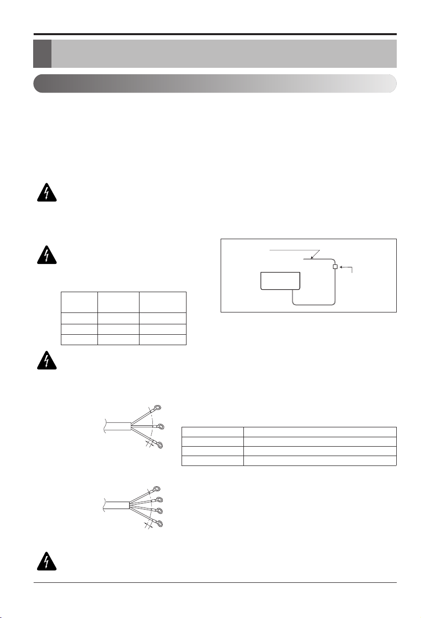
Always perform grounding.
• Otherwise, it may cause electri-
cal shock.
Don’t use a power cord, a
plug or a loose socket which
is damaged.
• Otherwise, it may cause a fire or
electrical shock.
For installation of the product,
always contact the service cen-
ter or a professional installation
agency.
• Otherwise, it may cause a fire,
electrical shock, explosion or in-
jury.
Securely attach the electrical
part cover to the indoor unit
and the service panel to the
outdoor unit.
• If the electrical part cover of the
indoor unit and the service panel
of the outdoor unit are not at-
tached securely, it could result in
a fire or electric shock due to
dust, water, etc.
Always install an air leakage
breaker and a dedicated
switching board.
• No installation may cause a fire
and electrical shock.
Do not keep or use flammable
gases or combustibles near
the air conditioner.
• Otherwise, it may cause a fire or
the failure of product.
Ensure that an installation frame of the out-
door unit is not damaged due to use for a long
time.
• It may cause injury or an accident.
Do not disassemble or repair the product ran-
domly.
• It will cause a fire or electrical shock.
Installation Manual 7
ENGLISH
Safety Precautions
Do not install the product at a place that there
is concern of falling down.
• Otherwise, it may result in personal injury.
Use caution when unpacking and installing.
• Sharp edges may cause injury.
Take the power plug out if
necessary, holding the head
of the plug and do not touch
it with wet hands.
• Otherwise, it may cause a fire
or electrical shock.
Do not use the power cord
near the heating tools.
• Otherwise, it may cause a fire
and electrical shock.
Do not open the suction
inlet of the indoor/outdoor
unit during operation.
• Otherwise, it may electrical
shock and failure.
Do not allow water to run
into electrical parts.
• Otherwise, it may cause the
failure of machine or electrical
shock.
Hold the plug by the head
when taking it out.
• It may cause electric shock
and damage.
Never touch the metal parts
of the unit when removing
the filter.
• They are sharp and may
cause injury.
Do not step on the
indoor/outdoor unit and do
not put anything on it.
• It may cause an injury through
dropping of the unit or falling
down.
Do not place a heavy object
on the power cord.
• Otherwise, it may cause a fire
or electrical shock.
When the product is sub-
merged into water, always
contact the service center.
• Otherwise, it may cause a fire
or electrical shock.
Do not share the outlet with
other appliances.
•
It will cause an electric shock or
a fire due to heat generation.
Do not use the damaged
power cord.
• Otherwise, it may cause a fire
or electrical shock.
Do not modify or extend the
power cord randomly.
• Otherwise, it may cause a fire
or electrical shock.
Take care so that the power
cord may not be pulled dur-
ing operation.
• Otherwise, it may cause a fire
or electrical shock.
Unplug the unit if strange
sounds, smell, or smoke
comes from it.
• Otherwise, it may cause elec-
trical shock or a fire.
Keep the flames away.
• Otherwise, it may cause a fire.
Take care so that children may not step on the outdoor unit.
• Otherwise, children may be seriously injured due to falling down.
n Operation
Use a vacuum pump or Inert (nitrogen) gas when doing leakage test or air purge. Do not compress air
or Oxygen and Do not use Flammable gases. Otherwise, it may cause fire or explosion.
•
There is the risk of death, injury, fire or explosion.

8 Multi Air Conditioner
Safety Precautions
CAUTION
n Installation
Install the drain hose to ensure that drain
can be securely done.
• Otherwise, it may cause water leakage.
Install the product so that the noise or hot
wind from the outdoor unit may not cause
any damage to the neighbors.
• Otherwise, it may cause dispute with the neigh-
bors.
Always inspect gas leakage after the instal-
lation and repair of product.
• Otherwise, it may cause the failure of product.
Keep level parallel in installing the product.
• Otherwise, it may cause vibration or water leak-
age.
Please install safely at a place that can suffi-
ciently endure the weight of the product.
• If the strength is not sufficient, the product may
fall and cause injury.
Avoid excessive cooling and perform venti-
lation sometimes.
• Otherwise, it may do harm to your health.
Use a soft cloth to clean. Do not use wax,
thinner, or a strong detergent.
• The appearance of the air conditioner may de-
teriorate, change color, or develop surface
flaws.
Do not use an appliance for special purposes
such as preserving animals vegetables, preci-
sion machine, or art articles.
• Otherwise, it may damage your properties.
Do not place obstacles around the flow inlet
or outlet.
• Otherwise, it may cause the failure of appliance
or an accident.
n Operation
Installation Manual 9
ENGLISH
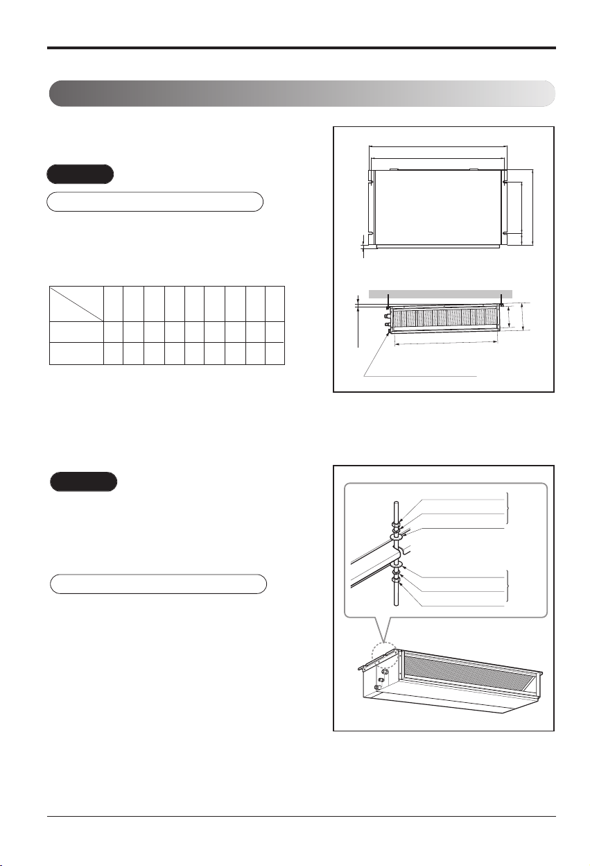
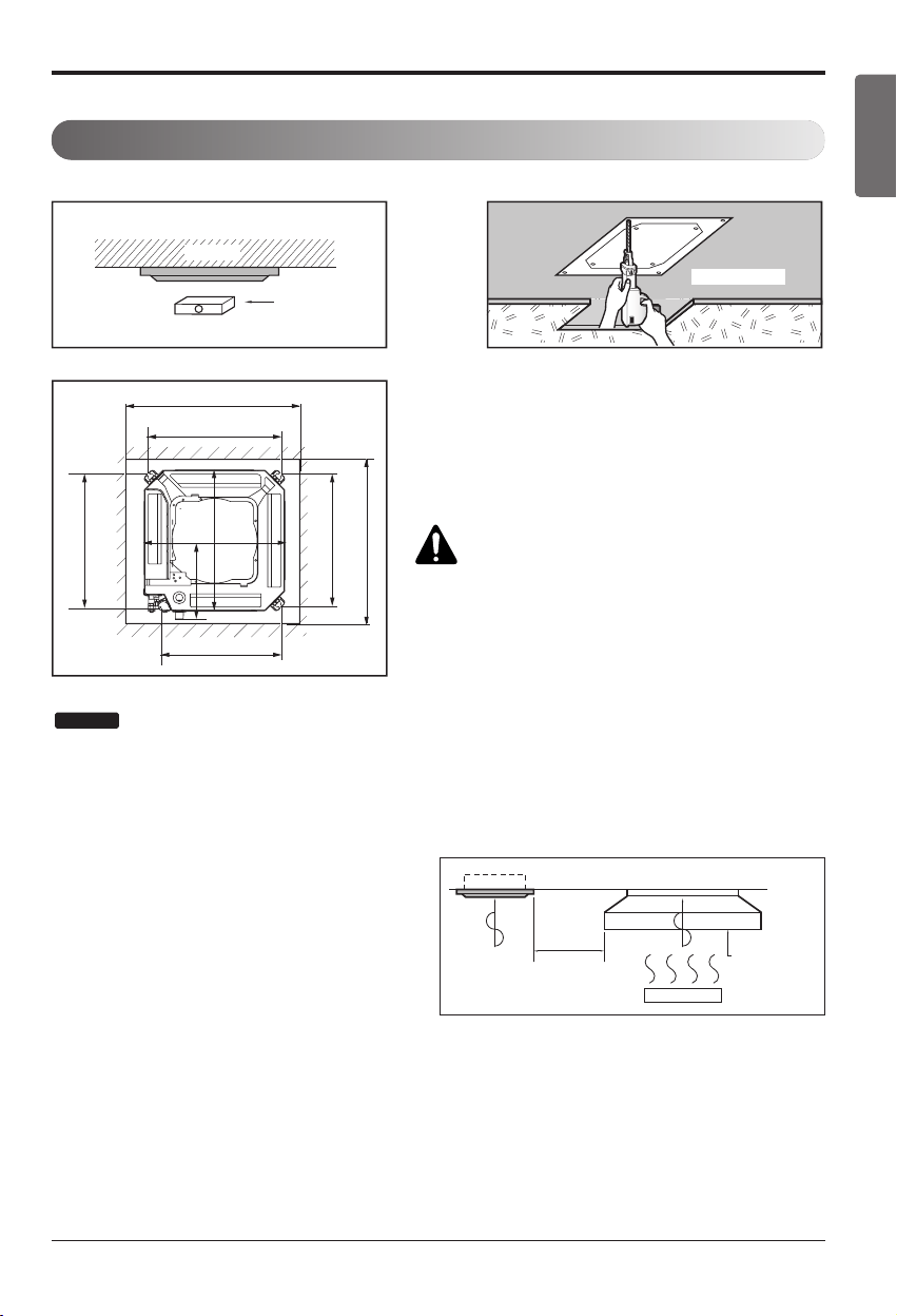
Installation of Indoor, Outdoor Unit
Installation of Indoor, Outdoor Unit
Read completely, then follow step by step.
You need to select adequate installation location considering the following conditions, and make sure
to acquire the consent of the user.
Indoor unit
1. Do not have any heat or steam near the unit.
2. Select a place where there are no obstacles
in front of the unit.
3. Make sure that condensation drainage can be
conveniently routed away.
4. Do not install near a doorway.
5. Ensure the unit is unobstructed, allow proper
space on all sides according to the arrows
and distance measurements in the figures.
6. Use a Metal Detector or Metal Scanner to lo-
cate studs to prevent unnecessary damage to
the wall.
Select the best location
Top view
Front view
H=20(25/32) or more
Service Space
Ceiling
A
B
Capacity(Btu/h class)
AB
9/12k 600(23-5/8) 900(35-7/16)
18k 600(23-5/8) 1100(43-5/16)
Unit:mm(inch)
[Ceiling Concealed Duct Type] [Ceiling Cassette Type]
* Suitable dimention “H” is necessary to get a slope to
drain as show in the figure.
600
(23-5/8)
600
(23-5/8)
Inspection hole
[600(23-5/8) x 600(23-5/8)]
Control box
Ceiling
Ceiling Board
Ceiling Board
Floor
Unit:mm(inch)
At least 1800(70-
7
/
8
)
3600(141-
23
/
32
) or less
1000(39-
3
/
8
)
or more
500(19-
11
/
16
)
or more
10(
13
/
32
)
or more
500(19-
11
/
16
)
or more
300(11-
13
/
16
) or less
30(1-3/16)
±3(1/8)
More than 200(7-7/8)
Recommended height
2000(78-3/4)
More than
100(3-15/16)
More than
100(3-15/16)
Unit:mm(inch)
[Standard/Standard Libero/Artcool Mirror/Artcool Libero Type]
❈
Note : remove obstructions to prevent blockage of airflow path
10 Multi Air Conditioner
Installation of Indoor, Outdoor Unit
Outdoor unit
1. If an awning is built over the unit to prevent di-
rect sunlight or rain exposure, make sure that
heat radiation from the condenser is not re-
stricted.
2. Ensure the unit is unobstructed, allow proper
space on all sides according to the arrows
and distance measurements in the figures.
3. Do not place animals and plants in the path of
the warm air.
4. Take the air conditioner weight into account
and select a place where noise and vibration
are minimum.
5.
Select a place so that the warm air and sound
from the air conditioner does not disturb
neighbors.
6. Place that can sufficiently endure the weight
and vibration of the outdoor unit and where
even installation is possible.
7. Place that has no direct influence of snow or
rain.
8. Place with no danger of snowfall or icicle drop.
9. Place without weak floor or base such as de-
crepit part of the building or with a lot of snow
accumulation.
Rooftop Installations:
If the outdoor unit is installed on a roof structure,
be sure to level the unit. Ensure the roof struc-
ture and anchoring method are adequate for the
unit location. Consult local codes regarding
rooftop mounting.
more than 700
(27 9/16)
more than 300
(11 13/16)
more than 300
(11 13/16)
more than 600
(23 21/32)
more than 300
(11 13/16)
more than 300
(11 13/16)
Unit:mm(inch)
Unit:mm(inch)
Installation Manual 11
ENGLISH
Installation of Indoor, Outdoor Unit
Seaside Applications and Installation
1.
Air conditioners should not be installed in areas where corrosive gases, such as acid or alkaline gas, are
produced.
2. Do not install the product where it could be exposed to sea wind (salty wind) directly. It can result
corrosion on the product. Corrosion, particularly on the condenser and evaporator fins, could
cause product malfunction or inefficient performance.
3. If outdoor unit is installed close to the seaside, it should avoid direct exposure to the sea wind.
1) If the outdoor unit is to be installed close to the seaside, direct exposure to the sea wind should be avoided.
Install the outdoor unit on the opposite side of the sea wind direction.
2)
In case, to install the outdoor unit on the seaside, set up a windbreaker/barrier, to lessen the unit's exposure to sea air
3) Place with fluent water draining
- Install at a place with fluent water draining to prevent damage from localized heavy rain and avoid frequent
flooded area.
• It should be strong enough (like concrete) to obstruct
the wind from the sea.
• The height and width should be more than 150% of
the outdoor unit.
• A minimum of 70cm (27 1/16 inches)
of space between outdoor unit and the windbreak
for easy air flow.
Sea wind Sea wind
Sea wind
Windbreaker/Barrier
Periodic ( more than once/year ) cleaning of the dust or salt particles stuck on the heat exchanger
using water is recommended.
1. Selecting the location(Outdoor Unit)
12 Multi Air Conditioner
Installation of Indoor, Outdoor Unit
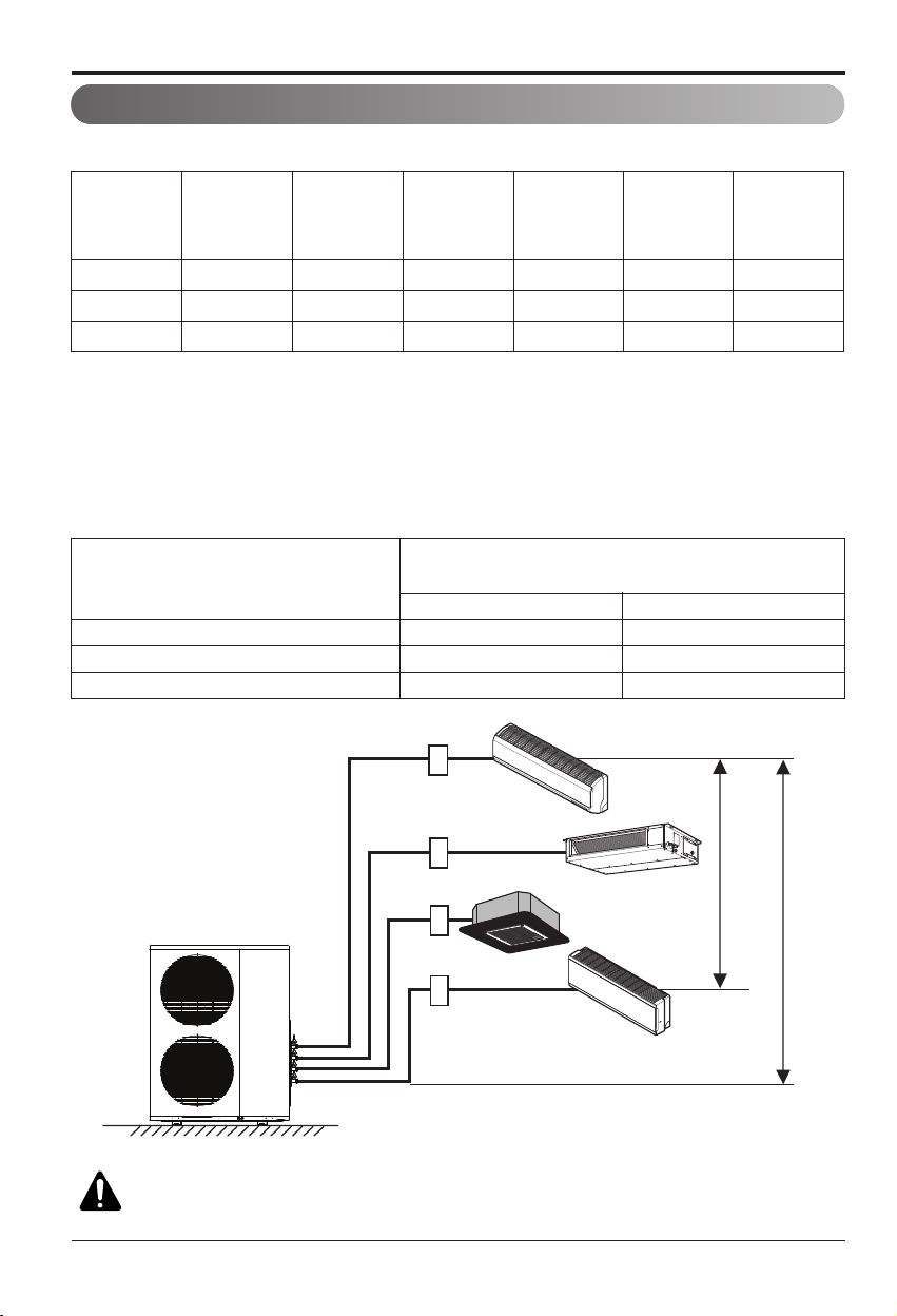
Multi Piping Type
Piping length and elevation
h2
A
B
C
D
h1
CAUTION: Capacity is based on standard length and maximum allowance
length is on the basis of reliability.
Unit : m(ft)
18k 50(164) 25(82) 3(10) 15(49) 7.5(25) 24k
24k 75(246) 25(82) 3(10) 15(49) 7.5(25) 33k
36k 75(246) 25(82) 3(10) 15(49) 7.5(25) 48k
Outdoor Unit
Capacity
(Btu/h class)
Max total length
of all pipes
(A+B)/(A+B+C)/
(A+B+C+D)
Max length of
each pipe
(A/B/C/D)
Min length of
each pipe
(A/B/C/D)
Max Elevation
between each
indoor unit and
outdoor unit (h1)
Max elevation
between indoor
units (h2)
Max.Combination
of Indoor unit
(Btu/h class)
Indoor unit Capacity (Btu/h class)
Pipe Diameter
Unit : mm(inch)
Gas Liquid
9k 9.52(3/8) 6.35(1/4)
12k 9.52(3/8) 6.35(1/4)
18k 12.7(1/2) 6.35(1/4)
Calculation method for total capacity index = sum up the capacity index of connected indoor units.
h Total capacity index = [Sum of all VAHU & Ceiling Concealed Duct (High Static) type indoor units capacity (if
any)] x 1.3 + Sum of all other indoor unit’s capacity
h The multiplier(1.3) is only necessary for calculation of combination ratio.
h For combinations where it contains one of below conditions, multiplier is 1.2 instead of 1.3. (See example 3)
1) ONE 24k high static ducted unit/VAHU AND ONE 24k high static ducted unit/VAHU
2) ONE 24k high static ducted unit/VAHU AND ONE 36K high static ducted unit/VAHU
Installation Manual 13
ENGLISH
Installation of Indoor, Outdoor Unit
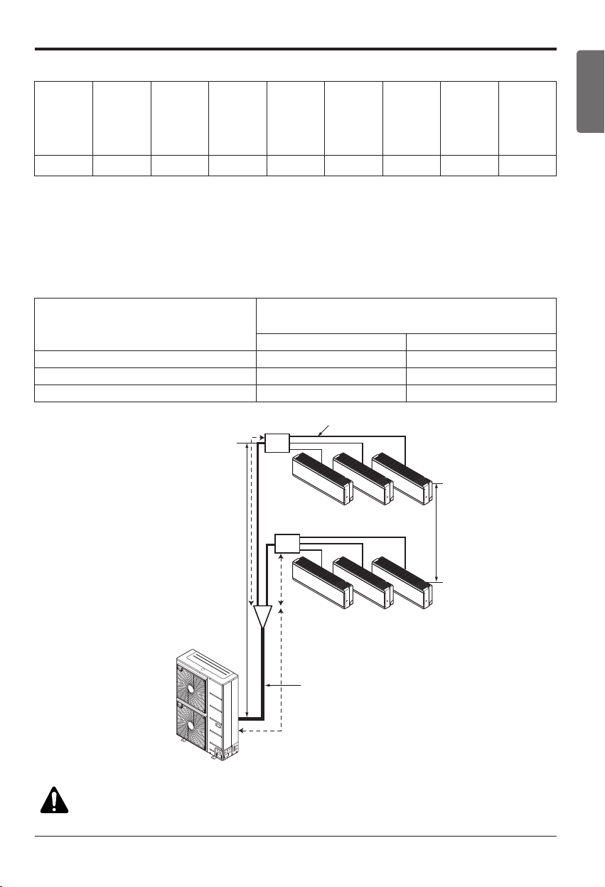
Distributor Piping Type
2
h1
C
Branch Pipe
Main Pipe
Distributor
Distributor
A
B
h2
CAUTION: Capacity is based on standard length and maximum allowance
length is on the basis of reliability.
Unit : m(ft)
Outdoor Unit
Capacity
(Btu/h class)
Max total length
of all pipes
(Main + Branch
pipes)
Max length
of
Main pipe
(A+B+C)
Max length
of
Branch
pipes
Max length
of each
Branch pipe
Min length of
each pipe
(Main /
Branch
pipes)
Max Elevation
Between each
indoor unit and
outdoor unit
(h1)
Max Eleva-
tion
Between in-
door
(h2)
Max Combi-
nation
of indoor
unit
54k 145(476) 55(180) 90(295) 15(49) 3(10) 30(98) 15(49) 73k
Indoor unit Capacity (Btu/h class)
Pipe Diameter
Unit : mm(inch)
Gas Liquid
9k 9.52(3/8) 6.35(1/4)
12k 9.52(3/8) 6.35(1/4)
18k 12.7(1/2) 6.35(1/4)
Calculation method for total capacity index = sum up the capacity index of connected indoor units.
h Total capacity index = [Sum of all VAHU & Ceiling Concealed Duct (High Static) type indoor units capacity (if
any)] x 1.3 + Sum of all other indoor unit’s capacity
h The multiplier(1.3) is only necessary for calculation of combination ratio.
h For combinations where it contains one of below conditions, multiplier is 1.2 instead of 1.3. (See example 3)
1) ONE 24k high static ducted unit/VAHU AND ONE 24k high static ducted unit/VAHU
2) ONE 24k high static ducted unit/VAHU AND ONE 36K high static ducted unit/VAHU
14 Multi Air Conditioner
Installation
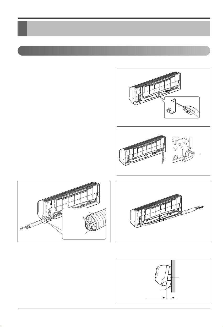
# Standard / Artcool Mirror Type
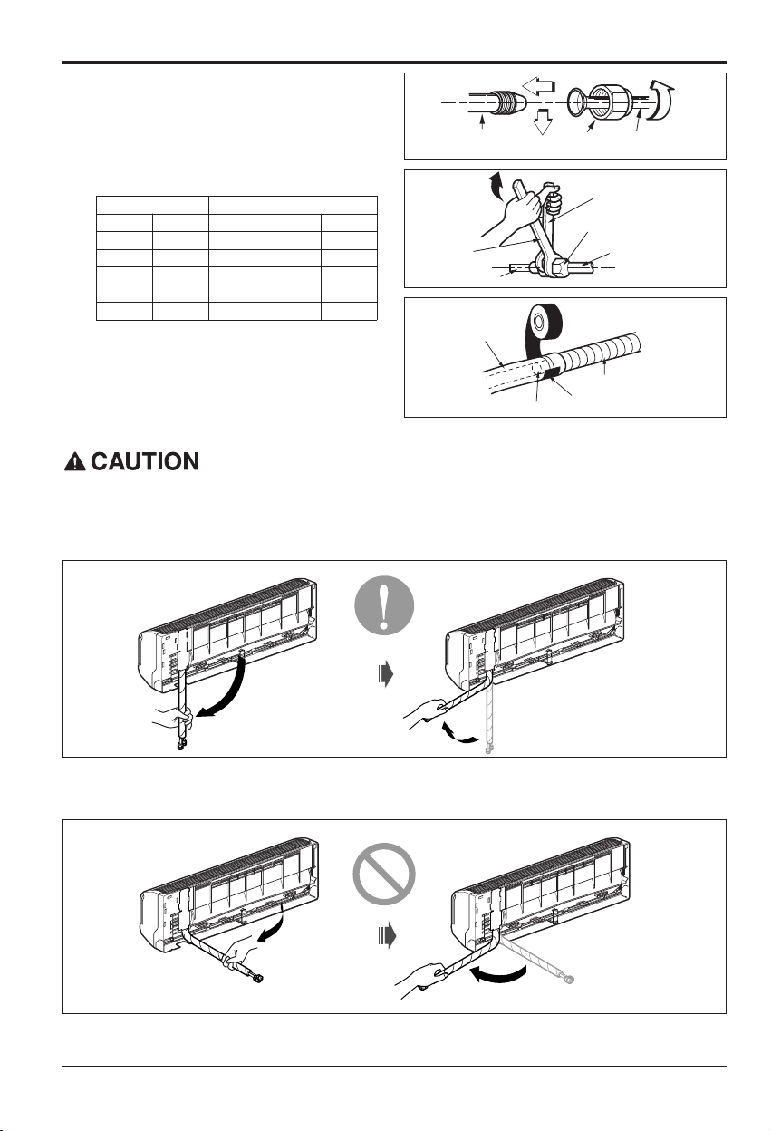
1. Prepare the indoor unit's piping and drain
hose for installation through the wall.
2. Remove the plastic tubing retainer(see the il-
lustration on the right) and pull the tubing and
drain hose away from chassis.
3. Route the indoor tubing and the drain hose to
the required piping hole position.
4. Insert the piping, drain hose, and the connect-
ing cable into the piping hole.
5.
Insert the connecting cable into the indoor unit.
• Don't connect the cable to the indoor unit.
• Make a small loop with the cable for easy
connection later.
6. Tape the tubing and drain hose.
7. Indoor unit installation
• Hang the indoor unit from the hooks at the
top of the installation plate.
• Insert the spacer etc. between the indoor
unit and the installation plate and separate
the bottom of the indoor unit from the wall.
Drain pipe
Connecting
pipe
Tape
Drain hose
Installation plate
Spacer
Indoor unit
80(3 5/32)
For right rear piping For left rear piping
Installation
Connecting the piping
[Standard / Standard Libero / Artcool Mirror Type]
Installation Manual 15
ENGLISH
Installation
# Standard Libero / Artcool Libero Type
1. Pull the screw cap at the bottom of the
indoor unit
2. Remove the chassis cover from the unit
by loosing screws
3. Pull back the tubing holder.
4. Remove pipe port cover and positioning
the tubing
Chassis cover
Right
Indoor unit back side view
Tubing holder
Backwards
Left
Pipe Port
5. Indoor unit installation
1) Hook the indoor unit onto the upper portion
of the installation plate.( engage the three
hooks at the top of the indoor unit with the
upper edge of the installation plate) Ensure
that the hooks are properly seated on the
installation plate by moving it left and right
2) Unlock the tubing holder from the chassis
and mount between the chassis and
installation plate in order to separate the
bottom side of the indoor unit from the wall
Tubing Holder
Installation plate
16 Multi Air Conditioner
Installation
Connecting the piping to the indoor unit
and drain hose to drain pipe.
1. Align the center of the pipes and suffi-
ciently tighten the flare nut by hand.
2. Tighten the flare nut with a wrench.
3. Next, extend the indoor unit's drain hose.
Then attach the drain pipe.
Indoor unit tubing Flare nut Pipes
Wrench
Indoor unit tubing
Open-end wrench (fixed)
Connection pipe
Flare nut
Vinyl tape(narrow)
Adhesive
Drain pipe
Indoor unit drain hose
Installation Information. For left piping. Follow the instruction below.
Good case
• Press on the upper side of clamp and unfold the tubing to slowly downward.
Bad case
• Bending the pipe from right to left may cause damage to the tubing.
Outside diameter Torque
mm inch N. m kgf.m lbf.ft
Ø6.35 1/4 14~18 1.4~1.8 10~13
Ø9.52 3/8 34~42 3.5~4.3 25~31
Ø12.7 1/2 49~61 5.0~6.2 36~45
Ø15.88 5/8 69~82 7.0~8.4 51~60
Ø19.05 3/4 100~120 10.0~12.2 73~88
Installation Manual 17
ENGLISH
Installation
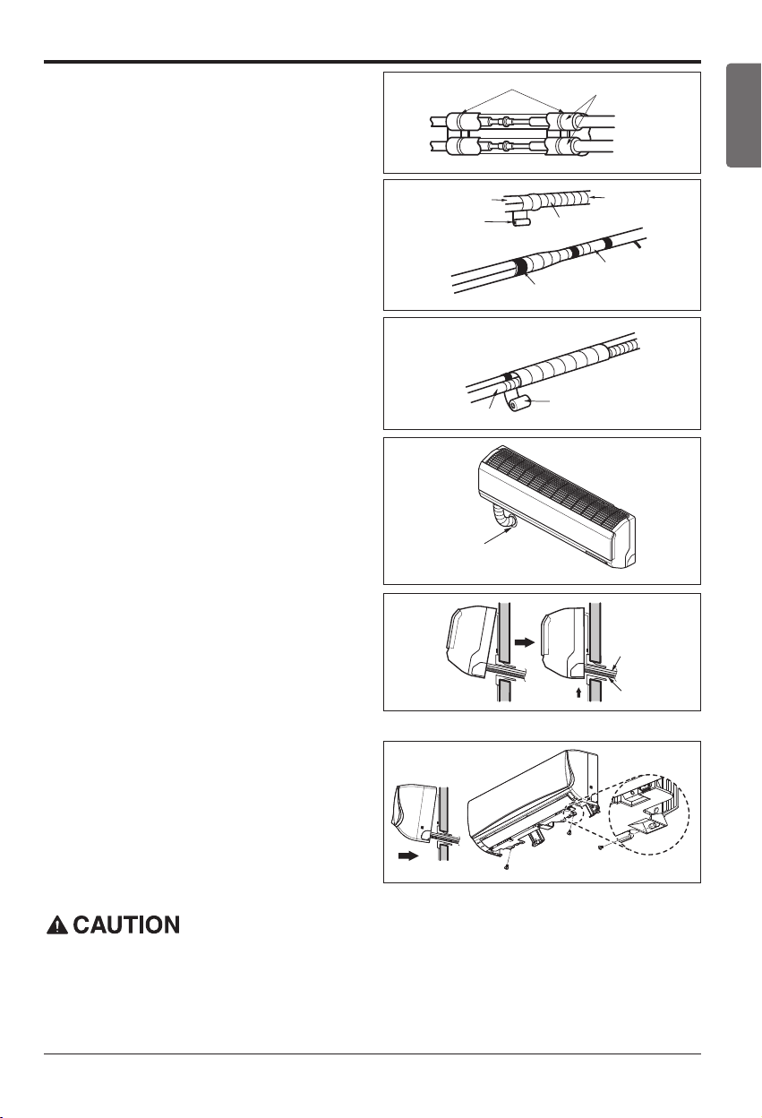
Wrap the insulation material around the con-
necting portion.
1. Overlap the connection pipe insulation and the
indoor unit pipe heat insulation material. Bind
them together with vinyl tape so that there is no
gap.
2. Wrap the area which accommodates the rear
piping housing section with vinyl tape.
3. Bundle the piping and drain hose together by
wrapping them with vinyl tape over the range
within which they fit into the rear piping housing
section.
Reroute the pipings and the drain hose across
the back of the chassis.
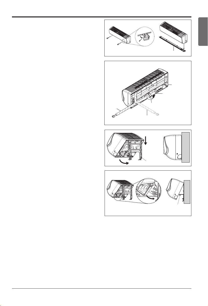
Finishing the indoor unit installation
# Standard / Artcool Mirror Type
1. Remove the spacer.
2. Ensure that the hooks are properly seated on
the installation plate by moving it left and right.
3. Press the lower left and right sides of the unit
against the installation plate until the hooks en-
gage into their slots(clicking sound).
# Standard Libero / Artcool Libero Type
1.
Mount the tubing holder in the original positon.
2.
Ensure that the hooks are properly seated on the
installation plate by moving it left and right.
3. Press the lower left and right sides of the unit
against the installation plate until the hooks
engage into their slots (clicking sound).
4.
Finish the assembly by screwing the unit to the
installation plate by using two pieces of type "C"
screws. And assemble a chassis cover.
Plastic bands
Insulation material
Vinyl tape(narrow)
Connection pipe
Vinyl tape (wide)
Wrap with vinyl tape
Indoor unit pipe
Pipe
Drain hose
Vinyl tape(wide)
Piping for
passage through
piping hole
Drain hose
Connecting
Type 'C' screw
If the split type Indoor unit is installed in a wall having hole or opening near by or back side of the
unit, then the air from other side of the wall can come inside the condition space through that hole /
opening. That air can cause unwanted dew / water droplet formation when it comes in contact with
body of the indoor unit. So all hole or opening on the wall must be blocked very well to avoid water
dropping from the body of the unit.
18 Multi Air Conditioner
Installation
The wall you select should be strong and solid enough to prevent vibration
1. Mount the installation plate on the wall with
type "A" screws. If mounting the unit on a concrete wall, use anchor bolts.
• Mount the installation plate horizontally by aligning the centerline using a level.
2. Measure the wall and mark the centerline. It is also important to use caution concerning the lo-
cation of the installation plate-routing of the wiring to power outlets is through the walls typically.
Drilling the hole through the wall for piping connections must be done safely.
How To Fix
Installation of filters
1) Detach two attached tapes from the plasma
filter.
Plasma Filter
Ø70
(2 3/4)
Ø70
(2 3/4)
110(4 11/32)
110
(4 11/32)
90
(3 17/32)
70
(2 3/4)
Chassis
Hook
Installation Plate
Type “A”
Left rear piping Right rear piping
Ø70
(2 3/4)
133(5 1/4)
Ø70
(2 3/4)
100(3 15/16)
Chassis
Hook
Installation Plate
Type “A”
Left rear piping Right rear piping
Ø70
(2 3/4)
133(5 1/4)
95(5 3/4)
217(8 17/32)
175(6 7/8)
442(17 13/32) 442(17 13/32)
Ø70
(2 3/4)
Installation Plate
Enganche
del chasis
Type "A" Screws
Right rear piping
Left rear piping
Installation Plate
Place a level on raised tab
Unit Outline
Chassis
Hook
Installation Plate
Type “A”
Unit
Outline
Left Rear
Piping
Right Rear
Piping
Place a level on raised tab
(Unit : mm)
Installation plate
Ø65
Ø65
184
220
156
307
765064
Ø70
(2 3/4)
Ø70
(2 3/4)
69(2 23/32)
56(2 7/32)
207(8 5/32)
105(4 1/8)
460(18 1/8) 570(22 7/16)
Installation Plate
Enganche
del chasis
Type "A" Screws
Left rear piping
Installation Plate
Place a level on raised tab
Unit Outline
Right
rear
piping
Measuring Tape
Hanger
Measuring Tape
<Type 1> <Type 2>
<Type 3>
<Type 5>
<Type 4>
Indoor Type
Capacity (kBtu/h)
Type
Standard / Standard Libero /
Artcool Mirror / Artcool Libero
9/12
Type 1 / Type 3
18
Type 2 / Type 4 / Type 5
Installation Manual 19
ENGLISH
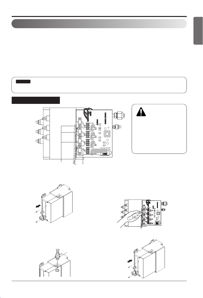
Installation
Wiring Connection
1. Connect the wires to the terminals on the con-
trol board individually according to the outdoor
unit connection.
• Ensure that the color of the wires of outdoor
unit and the terminal No. are the same as
those of indoor unit respectively.
2. Attach the Grille onto the cabinet.
• Grasp the lower left and right side of the
Grille and engage four tabs on the top inside
edge of the chassis.
• Press the Grille toward the chassis until it
goes back into place.
Connecting cable
Conduit connection
1. Set the connecting cable into the terminal
block of indoor unit, and tighten set screw to
lock the conduit bracket to the indoor unit.
2. Join the conduit and the conduit bracket to-
gether.
Connecting cable
Lock nut
Conduit
Conduit
bracket
Terminal Block in Indoor
1(L1) 2(L2) 3 4
Connected to Outdoor Unit
View
Terminal block
Connecting cable
Cable retainer
CAUTION :
Must use
the elbow type (L-Type)
conduit.
20 Multi Air Conditioner
Installation
[Ceiling Concealed Duct Type]
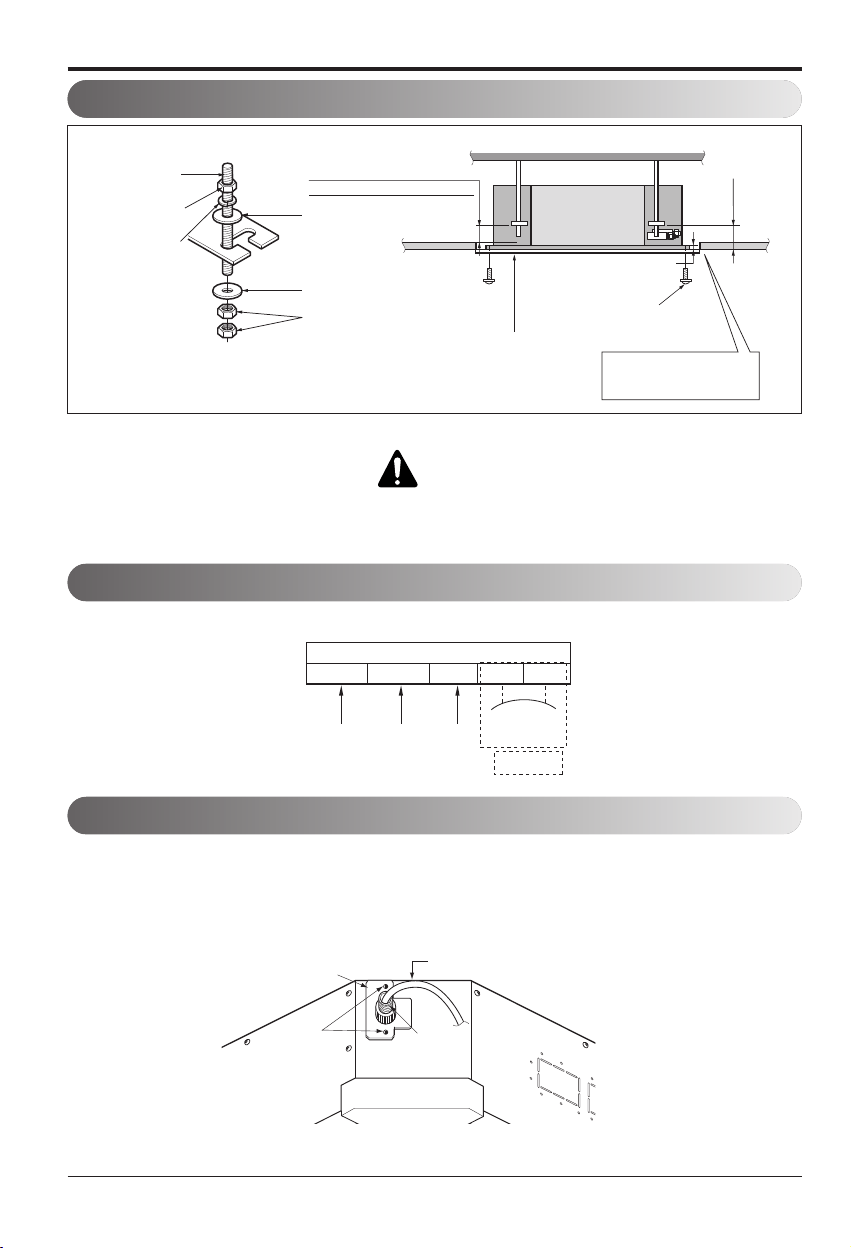
Ceiling dimension and hanging bolt location
Installation of Unit
Install the unit above the ceiling correctly.
• Apply a joint-canvas between the unit and duct to
absorb unnecessary vibration.
• Apply a filter Accessory at air return hole.
• Install the unit leaning to a drainage hole side as
a figure for easy water drainage.
• A place where the unit will be leveled and that
can support the weight of the unit.
• A place where the unit can withstand its vibration.
• A place where service can be easily performed.
CASE 1
POSITION OF SUSPENSION BOLT
CE
G
D
A
B
M10 Nut
M10 SP. washer
M10 washer
X 4
X 4
(Local
supply)
X 4
M10 Nut
M10 SP. washer
M10 washer
X 4
X 4
(Local
supply)
X 4
1/100
I
F
H
Drainage hole
CASE 2
POSITION OF CONSOLE BOLT
Unit:mm(inch)
9/12k
850 900 383 570 93.5 190 20.6 795 163
(33 15/32) (35 15/32) (15 3/32) (22 7/16) (3 11/16) (7 1/2) (13/16) (31 5/16) (6 13/32)
18k
1130 1180 383 570 93.5 190 20.6 1065 163
(44 1/2) (46 1/2) (15 3/32) (22 7/16) (3 11/16) (7 1/2) (13/16) (41 15/16) (6 13/32)
Dimension
Capacity
Btu/h class
ABCDEFGH I
Installation Manual 21
ENGLISH
Installation
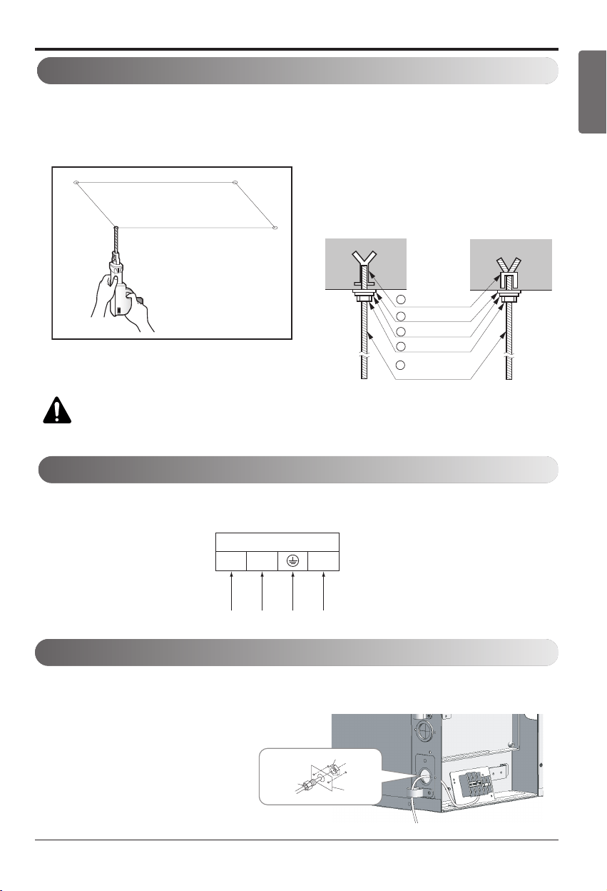
• Select and mark the position for fixing
bolts.
• Drill the hole for set anchor on the face of
ceiling.
• Insert the set anchor and washer onto the
suspension bolts for locking the suspen-
sion bolts on the ceiling.
• Mount the suspension bolts to the set an-
chor firmly.
• Secure the installation plates onto the
suspension bolts (adjust level roughly)
using nuts, washers and spring washers.
1 Set anchor
Old building New building
2 Plate washer
3 Spring washer
4 Nut
5 Suspension
bolts
How to Fix
CAUTION : Tighten the nut and bolt to prevent unit falling.
Connect the wires to the terminals on the control board individually according to the outdoor unit connection.
• Ensure that the color of the wires of outdoor unit and the terminal No. are the same as those of indoor unit respectively.
Terminal Block of Indoor Unit
1(L1) 2(L2) 3
Connected to outdooor unit
Wiring Connection
B1/B2 Series
Conduit connection
1. Remove the busing rubber product attached on the indoor unit.
2. Set the connecting cable into the terminal block of indoor unit, and tighten set screw to lock the
conduit bracket to the indoor unit.
3. Join the conduit and the conduit bracket to-
gether.
Lock nut
Conduit
mounting
plate
Conduit
22 Multi Air Conditioner
Installation
CAUTION
Ceiling
Drain Pump use
Drainage hole
Front of view
1. Install declination of the indoor unit is very important for the drain of the duct type air conditioner.
2. Minimum thickness of the insulation for the connecting pipe shall be 19mm(1/32 inch).
• The unit must be horizontal or declined to the drain hose connected when fin-
ished installation.
INSULATION, OTHERS
Insulate the joint and tubes completely.
All thermal insulation must comply with local requirement.
INDOOR UNIT
n After all workings are finished, check the working and operation.
• Air distribution ............... Is the air circulation good?
• Drain ............................. Is the drainage smoothly and no sweating?
• Gas leakage ................. Is the piping connection correctly?
• Wiring ........................... Is the wiring connection correctly?
• Lock-bolt ....................... Is the lock-bolt of compressor loosened?
• Insulation....................... Is the unit fully insulated?
• Ground .......................... Is the unit safely grounded?
THERMAL INSULATION
TEST AND CHECK
Make sure that there is no clearance here.
Overlap with thermal
insulator for piping.
Thermal insulator for refrigerant pipe
(Local supply)
Thermal insulator for
piping(Local supply)
Hose clip for thermal insulator(Local supply)
Union for gas pipe
Refrigerant pipe and thermal
insulator(Local supply)
Union for liquid pipe
Thermal insulator for refrigerant pipe
(Local supply)
Hose clip for thermal insulator
(Local supply)
Felt
Rubber
Insulation
No clearance
Cabinet
Installation Manual 23
ENGLISH
Installation
Installation of wired Remote Controller
CN-REMO
LO2K
J15
LO1K
LO1D
C07D
C01K
J14
CN-DISP
CN-M CN-ZONEC
IC01A
The position of the fixing screws
Side of
remote Controller
Side of
Indoor Unit
Main
indoor unit
Red Yellow Brown
Main frame
Fixing the
remote controller
20mm(25/32 inch)
1
Put the installation paper on the place and determine the
position and height of the fixing screws of the wired re-
mote controller.
• Refer to the printed side of the installation paper.
2
Plug the connecting cable into the indoor unit.
• The product is being shipped with the cable
connected only to the remote controller.
Fix the connecting cable with the cable rack.
3
Remove the installation paper before installing the
remote controller so that it can fit at the right place.
* Do not embed the remote controller into the wall.
(It may cause the breakdown of the
temperature sensor.)
* If you want to install a number of remote
controller at the same place in a vertical line,
install them at regular intervals of 20mm(25/32 inch).
(It may cause the breakdown of the temperature sensor.)
* Do not install the cable with a distance of 50m(164ft) or longer.
(This can cause communication error.)
* When installing the cable, check whether the connector between the remote controller and the
product is installed properly. The connector will not be connected when installed in opposite
sides.
o Supply the power after connecting wired remote controller.
When you need to change wired remote controller, switch off the main power and change it.
If the wired remote controller is changed before switching off the main power, the option function of
the indoor unit can't be used. (option function like "slo" fan speed selection)
24 Multi Air Conditioner
Installation
Wired remote controller switch information
Group control switch
1. For individual control/Master use
2. For group control/Slave use
Ceiling height selection switch
1. Low ceiling
2. Standard ceiling
3. High ceiling
Product selection switch
1. Cooling Only product
2. Heat Pump product
Indoor temperature sensor selection
switch
1. Use the temperature sensor on the remote
controller.
2. Use the temperature sensor on the product.
3. Use the sensors on the product and remote
controller.
• When changing the product selection switch and group control switch, the power must be recon-
nected to reflect the changes.
• The central control could operate inappropriately depends on indoor unit type, when the remote
controller is set as slave.
S/W 1
SWGR
SWHI
Room Temp. Sensing
Ceiling Height/Default E.S.P
Group Control
3
1
2
2
SWPD
SWTH
Select Product
2
1
1
321
Installation Manual 25
ENGLISH
Installation
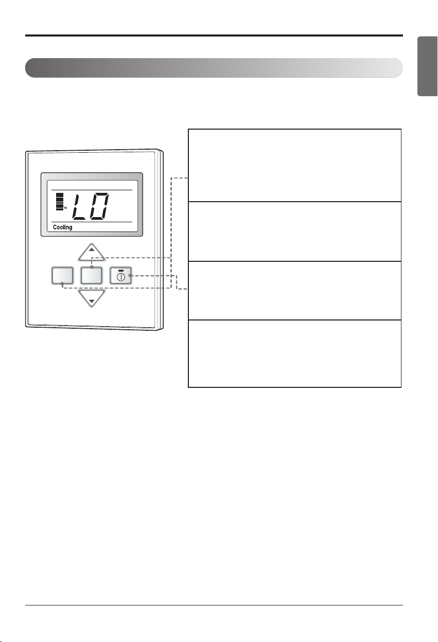
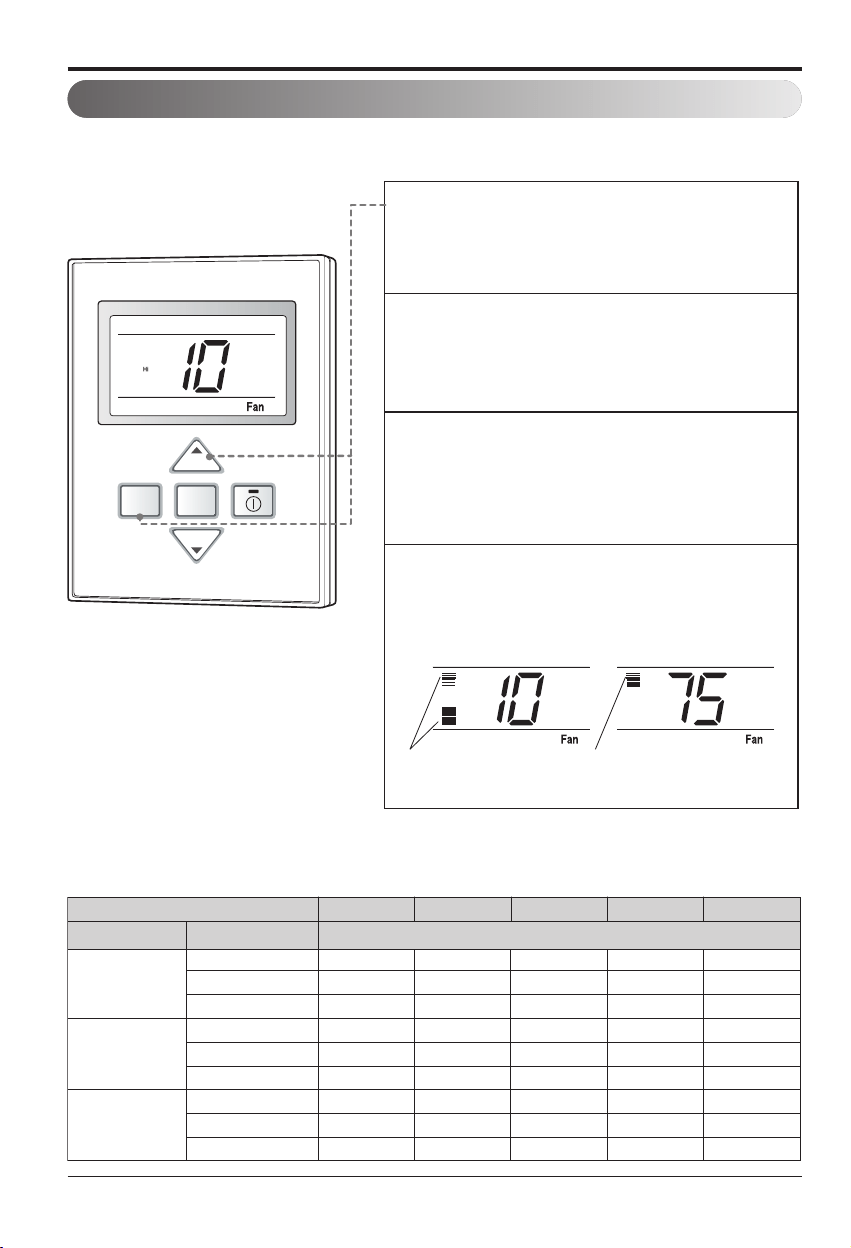
Trial Operation
The trial operation is to check the installation status of the product. The temperature will not be con-
trolled during trial operation. Instead the product will operate in several modes such as cooling,
strong wind, comp-on.
Out door
Room Temp
Total on
Central Run
Defrost Preheat
PQRCUCS0C
FAN
SPEED
MODE
TEMP
TEMP
1
If you want to set the trial operation mode, press
the mode button and the Fan speed button same
time for three seconds.
2
Then the product will begin the trial operation and
the display will be like as shown on left side pic-
ture.
3
If you want to cancel the trial operation mode, just
press the On/Off button.
4
The trail operation will be shut down automatically
after 18 minutes and system will go to the
standby mode.
n Necessary functions before using
26 Multi Air Conditioner
Installation
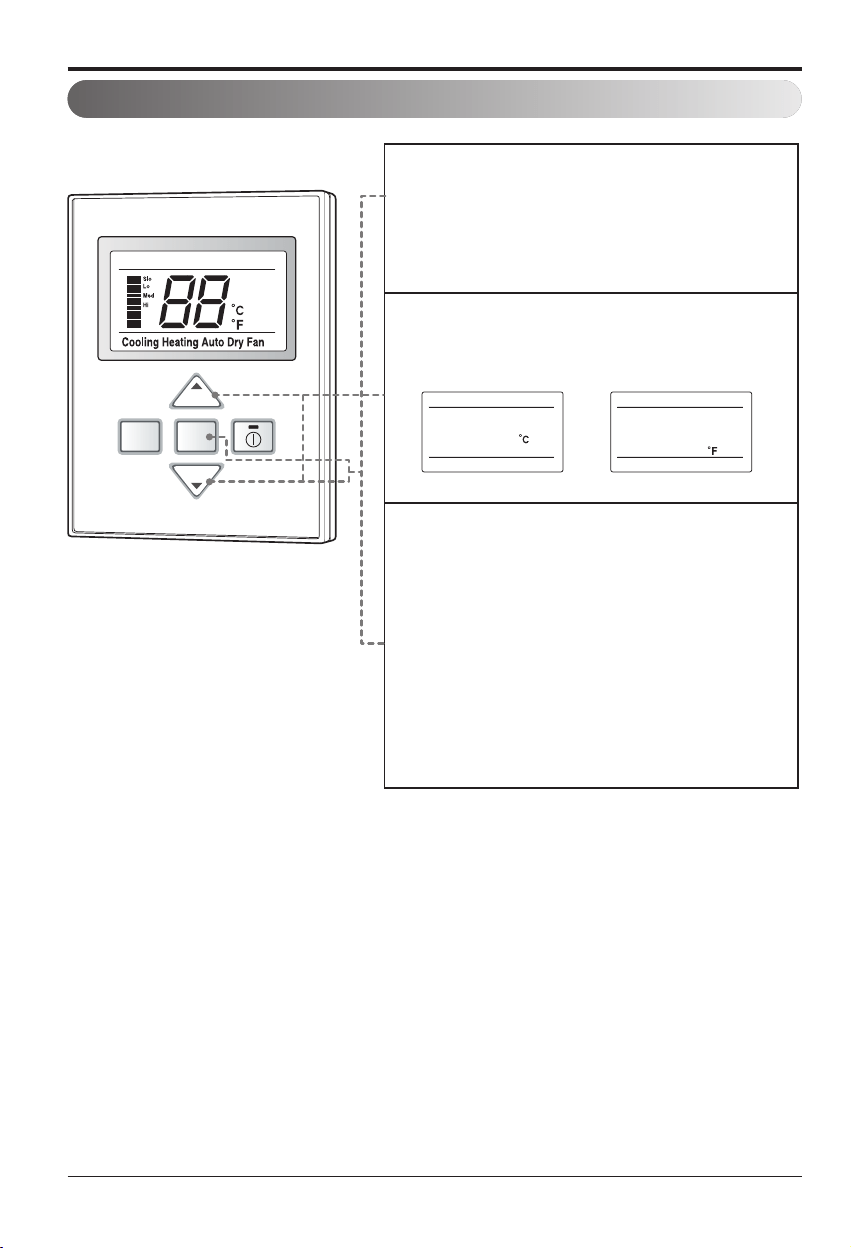
Celsius/Fahrenheit Switching
FAN
SPEED
MODE
Out door
Room Temp
Total on
Central Run
Defrost Preheat
Room Temp
Total on
Central Run
Defrost Preheat Out door
Out door
Room Temp
Total on
Central Run
Defrost Preheat
<Setting as Celsius> <Setting as Fahrenheit>
TEMP
TEMP
Room Temp
Total on
Central Run
Defrost Preheat Out door
PQRCUCS0C
1
If you want to change the temperature unit as the
Celsius or Fahrenheit, press the Temperature
control button(▼) and the Fan speed button
same time for three seconds to enter the setting
Mode.
2
Press the temperature control button to change
the unit.
Ex) Setting unit as Fahrenheit.
3
After setting, press the Temperature control but-
ton(▼) and the Fan speed button same time for
three seconds to exit the setting Mode.
The system will automatically release without
input after 30 seconds.
Installation Manual 27
ENGLISH
Installation
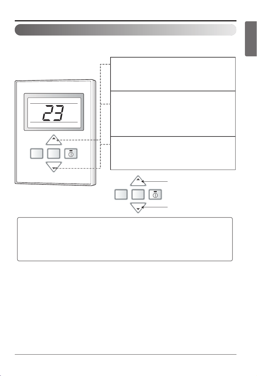
Setting the Central-Control Address
Note : The remote controller displays 'HL' if central controller has locked the remote controller .
Out door
Room Temp
Total on
Central Run
Defrost Preheat
PQRCUCS0C
FAN
SPEED
MODE
FAN
SPEED
MODE
Group No.
Indoor Unit No.
TEMP
TEMP
TEMP
TEMP
1
If you want to set the address on the display panel,
press both temperature control buttons (s/t)
same time for three seconds.
2
Press the temperature-increasing button to change
the group number. Press the temperature-decreasing
button to change the indoor unit number.
e.g. As shown on the left side panel, it displays 23.
Group No. : 2
Indoor Unit No. : 3
3
Set the address by pressing both temperature
control buttons again(s/t) at the same time for
three seconds.
• If you connect the indoor unit to the central controller, you should set the network ad-
dress of the indoor unit so that the central controller could recognize it.
• The center-control address is composed of the group number and the indoor-unit num-
ber.
Please set the address while using the central controller.
You don't need to set address if you don't use central controller.
28 Multi Air Conditioner
Installation
ESP Function
Out door
Room Temp
Total on
Central Run
Defrost Preheat
PQRCUCS0C
FAN
SPEED
MODE
Lo
Med
200
100
Setting the Low wind to 210 Setting the Medium wind to 175
TEMP
TEMP
1
Press the mode button and the temperature in-
creasing button(s) same time for three seconds.
2
Set the volume of each fan speed(Low, Medium, Hi)
by using the temperature control button. Press the
fan speed button to select the fan speed.
The value of E.S.P can be adjusted from 1 to 255.
3
If you press the On/Off button while setting the ESP
function, it will be canceled. (The picture on the left
side is the example of setting the Hi wind to ESP 10.)
4
Press the mode button and the temperature in-
creasing button (s) same time for three seconds.
Then the ESP setting will be activated after the
temperature display flashes three times.
E.S.P function is setting the volume of each fan speed. It is for the convenience of installation. It is
recommended that you should not use this function while using the remote controller.
EX)
h The E.S.P value is set at the proper value at the fac-
tory. So it is highly recommended that you should not
change the E.S.P value at your discretion.
Static pressure(mmAq)
Setting value
01234
Model name
Step(H/M/L)
8.5 CMM(300cfm) 75 84 94 104 114
7.5 CMM(265cfm) 69 77 88 99 110
6.5 CMM(230cfm) 62 71 83 95 106
9.5 CMM(335cfm) 82 90 99 109 118
8.5 CMM(300cfm) 75 84 94 104 114
7.5 CMM(265cfm) 69 77 88 99 110
15 CMM(530cfm) 90 97 105 114 122
13.5 CMM(477cfm) 82 90 99 109 119
11.5 CMM(406cfm) 75 84 93 103 114
AMNW09GB1A0
[LMDN095HV]
AMNW12GB1A0
[LMDN125HV]
AMNW18GB2A0
[LMDN185HV]
Installation Manual 29
ENGLISH
Installation
[Ceiling Cassette Type]
Ceiling dimension and hanging bolt location
Level gauge
Ceiling
Ceiling board
Unit: mm(inch)
585~660(23 1/16~26) (Ceiling Opening)
517(20 3/8)
461(18 5/32)
517(20 3/8)
585~660(23 1/16~26) (Ceiling Opening)
523(20 19/32)
570(22 15/32)
Unit Size
570(22 15/32)
Unit Size
319(12 9/16)
• The dimensions of the paper model for installation are the same as those of the ceiling opening dimensions.
• Avoid the following installation location.
1. Such places as restaurants and kitchen where considerable amount of oil steam and flour is generated.
These may cause heat exchange efficiency reduction, or water drops, drain pump mal-function.
In these cases, take the following actions;
• Make sure that ventilation fan is enough to cover all noxious gases from this place.
• Ensure enough distance from the cooking room to install the air
conditioner in such a place where it may not suck oily steam.
2. Avoid installng air conditioner in such places where cook-
ing oil or iron powder is generated.
3. Avoid places where inflammable gas is generated.
4. Avoid place where noxious gas is generated.
5. Avoid places near high frequency generators.
NOTICE
CAUTION :
• This air-conditioner uses a drain pump.
• Install the unit horizontally using a level
gauge.
• During the installation, care should be
taken not to damage electric wires.
• Select and mark the position for fixing bolts and piping
hole.
• Decide the position for fixing bolts slightly tilted to the
drain direction after considering the direction of drain
hose.
• Drill the hole for anchor bolt on the wall.
Use the ventilation fan
for smoke-collecting
hood with sufficient
capacity.
Cooking table
Air conditioner
Take enough
distance
30 Multi Air Conditioner
Installation
Set screw of
paper model (4 pieces)
Paper model
for installation
Ceiling board
150mm
(5-7/8 inch)
Ceiling board
Ceiling
Flat washer for M10
(accessory)
Keep the length of the bolt
from the bracket to 40mm(1-9/16 inch)
Open the ceiling board
along the outer edge of the
paper model
Flat washer for M10
(accessory)
Hanging bolt
(W3/8 or M10)
Nut
(W3/8 or M10)
Nut
(W3/8 or M10)
Spring washer
(M10)
Air Conditioner body
Keep the length of 31~34mm(1.22~1.34inch)
between the air conditioner bottom surfac
e and the ceiling surface
• The following parts are local purchasing.
① Hanging Bolt - W 3/8 or M10
② Nut - W 3/8 or M10
③ Spring Washer - M10
④ Plate Washer - M10
CAUTION : Tighten the nut and bolt to
prevent unit from falling off.
Wiring Connection
How to Fix
1(L1) 2(L2) 3 4 5
Terminal Block of Indoor Unit
Connected to outdoor unit
OPTION
TO AIR
FRESH
KIT
TQ/TR series
Connecting Cable
Conduit
Screw
Conduit bracket
Conduit connection
• Remove the busing rubber product attached on the indoor unit.
• Join the conduit and the conduit bracket together using nut.
• Set the connecting cable into the terminal block of indoor unit, and tighten set screw to lock the
conduit bracket to the indoor unit.
• Open the control box cover and connect the remote control cord and indoor power wires.
Installation Manual 31
ENGLISH
Installation
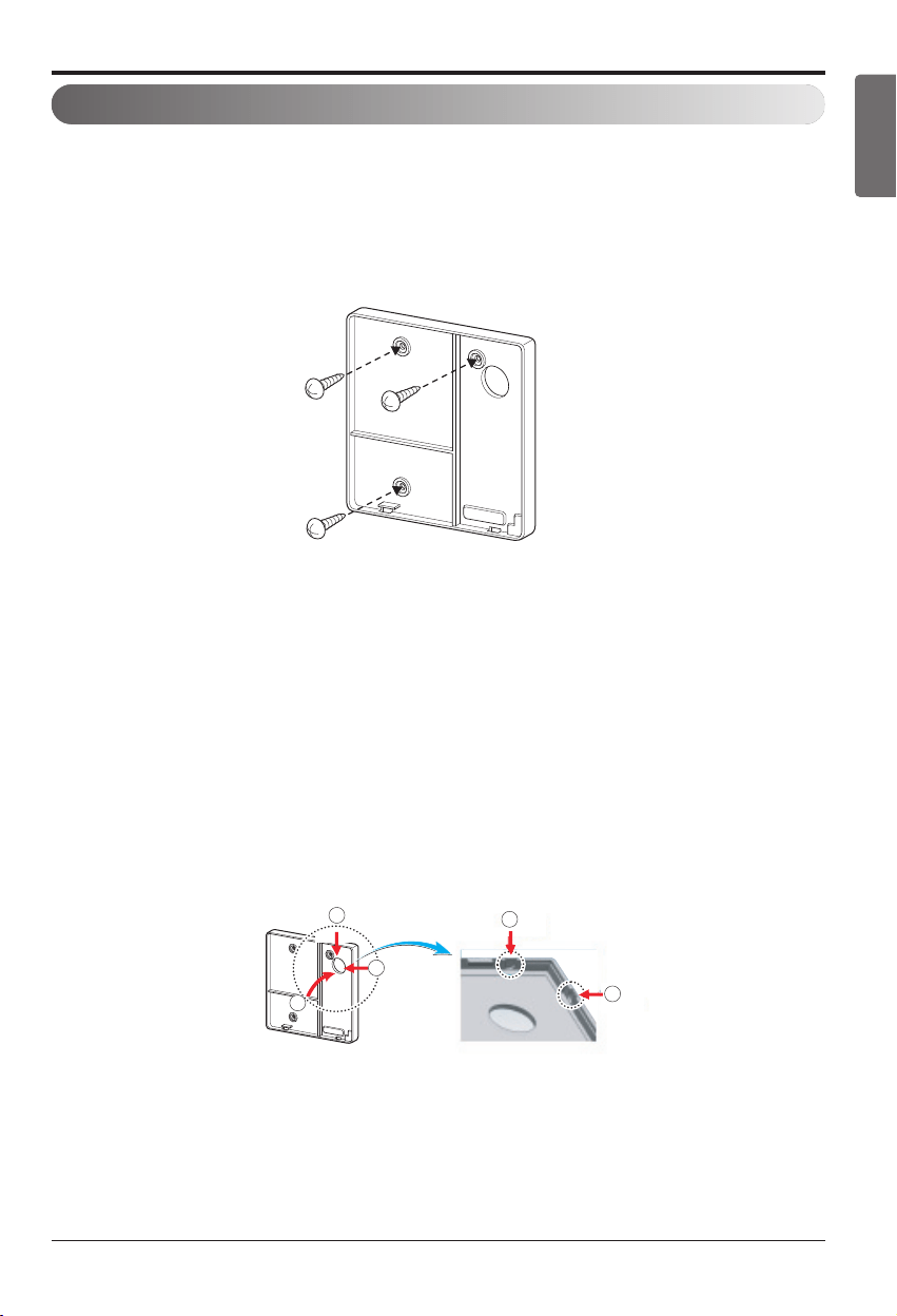
Installation of Wired Remote Controller(Optional)
1
2
3
2
3
<Wire guide grooves>
1. Please fix tightly using provided screw after placing remote controller setup board
on the place where you like to setup.
- Please set it up not to bend because poor setup could take place if setup board bends.
Please set up remote controller board fit to the reclamation box if there is a reclamation box.
- Install the product so as not to make a gap with the wall side and to prevent shaking after the installation.
2. Can set up Wired remote controller cable into three directions.
- Setup direction: the surface of wall reclamation, upper, right
- If setting up remote controller cable into upper and right side, please set up after removing remote
controller cable guide groove.
h
Remove guide groove with long nose.
①
Reclamation to the surface of the wall
②
Upper part guide groove
③
Right part guide groove
32 Multi Air Conditioner
Installation
Wall
Side
Wall
Side
Wall
Side
Wall
Side
<Connecting order>
<Separating order>
3. Please fix remote controller upper part into
the setup board attached to the surface of the
wall, as the picture below, and then, connect
with setup board by pressing lower part.
- Please connect not to make a gap at the remote controller
and setup board’s upper and lower, right and left part.
- Before assembly with the installation board, arrange the
Cable not to interfere with circuit parts.
When separating remote controller from setup
board, as the picture below, after inserting
into the lower separating hole using screw
driver and then, spinning clockwise, remote
controller is separated.
- There are two separating holes. Please individually
separate one at a time.
- Please be careful not to damage the inside
components when separating.
4. Please connect indoor unit and remote controller using connection cable.
5. Please use extension cable if the distance between wired remote controller and
indoor unit is more than 10m(32.8ft).
Please check if connector is normally connected.
Connecting cable
Indoor
Unit side
When installing the wired remote controller, do not bury it in the wall.
(It can cause damage in the temperature sensor.)
Do not install the cable to be 50m(164ft) or above.
(It can cause communication error.)
• When installing the extension cable, check the connecting direction of the connector of the remote
controller side and the product side for correct installation.
• If you install the extension cable in the opposite direction, the connector will not be connected.
• Specification of extension cable: 2547 1007 22# 2 core 3 shield 5 or above.
CAUTION
12V Red
Signal Yellow
GND Black
Installation Manual 33
ENGLISH
Installation
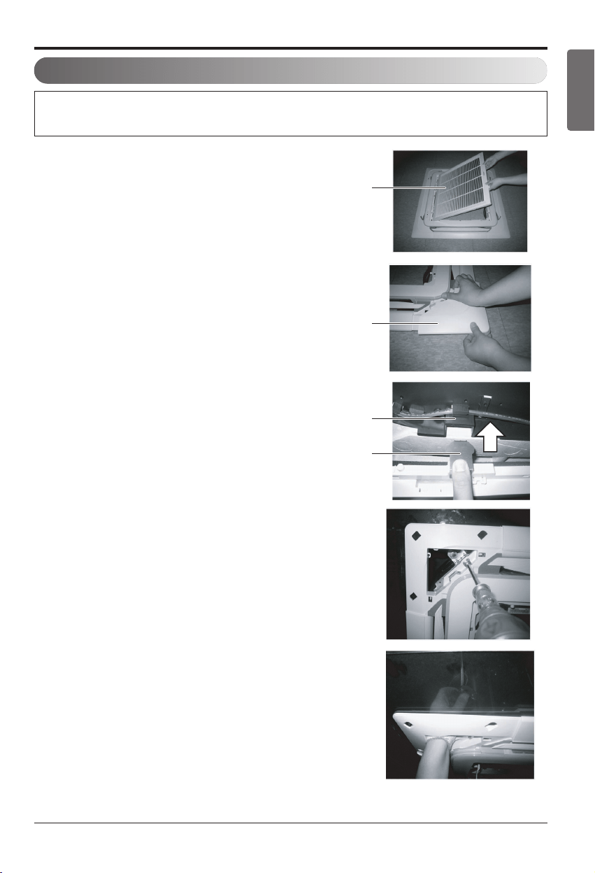
Installation of Decorative Panel
The decorative panel has its installation direction.
Before installing the decorative panel, always remove the paper template.
1. Remove the packing and take out air inlet
grille from front panel.
2. Remove the Corner covers of the panel.
3. Fit the panel on the unit by inserting
hooks as shown in picture.
4. Insert two screws on diagonal corners of
panel. Do not tighten the bolts completely.
(The fixing screws are included in the in-
door unit box.)
Check the alignment of panel with the
ceiling. Height can be adjusted using
hanging bolts as shown in picture. Insert
the other two screws and tighten all
screws completely.
Front grille
Coner cover
Hook clip
Hook
34 Multi Air Conditioner
Installation
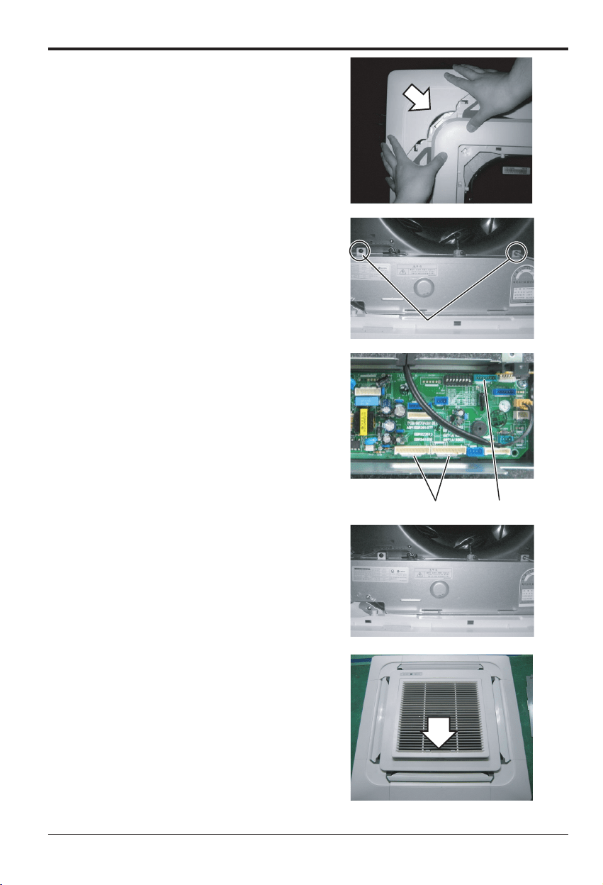
5. Fit the corner covers.
6. Open two screws of control panel cover.
7. Connect one display connector and two
vane control connectors of front panel to
indoor unit PCB.
The position marking on PCB is as:
Display connector : CN-DISPLAY
Vane control connector: CN-VANE 1,2
8. Close the cover for control box.
9. Install the air inlet grille and Filter on the
panel.
Screw
CN-VANE 1,2
CN-DISPLAY
Installation Manual 35
ENGLISH
Installation
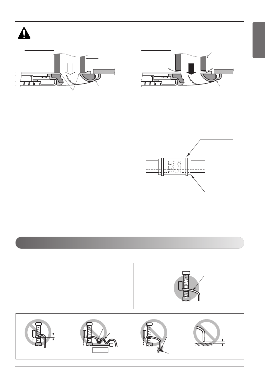
CAUTION:
Install certainly the decorative panel.
Cool air leakage causes sweating. Water drops fall.
Air conditioner
unit
Ceiling
board
Decorative panel
Decorative
panel
Fit the insulator (this part) and
be careful for cool air leakage
Good example
Air
Cool air leakage
(no good)
Bad example
Ceiling
board
Air conditioner unit
Flexible drain hose
HEAT INSULATION
1. Use the heat insulation material for the refrigerant piping which has an excellent heat-resis-
tance [over 120°C(248°F)].
2. Precautions in high humidity circum-
stance:
This air conditioner has been tested ac-
cording to the "KS Standard Conditions
with Mist" and confirmed that there is
not any default. However, if it is oper-
ated for a long time in high humid at-
mosphere [dew point temperature: more
than 23°C(73.4°F)], water drops are li-
able to fall. In this case, add heat insula-
tion material according to the following
procedure:
• Heat insulation material to be prepared... Adiabatic glass wool with thickness 10 to 20mm.
• Stick glass wool on all air conditioners that are located in ceiling atmosphere.
Indoor unit
Thermal insulator
(accessory)
Fastening band
(accessory)
Refrigerant piping
Drain Piping
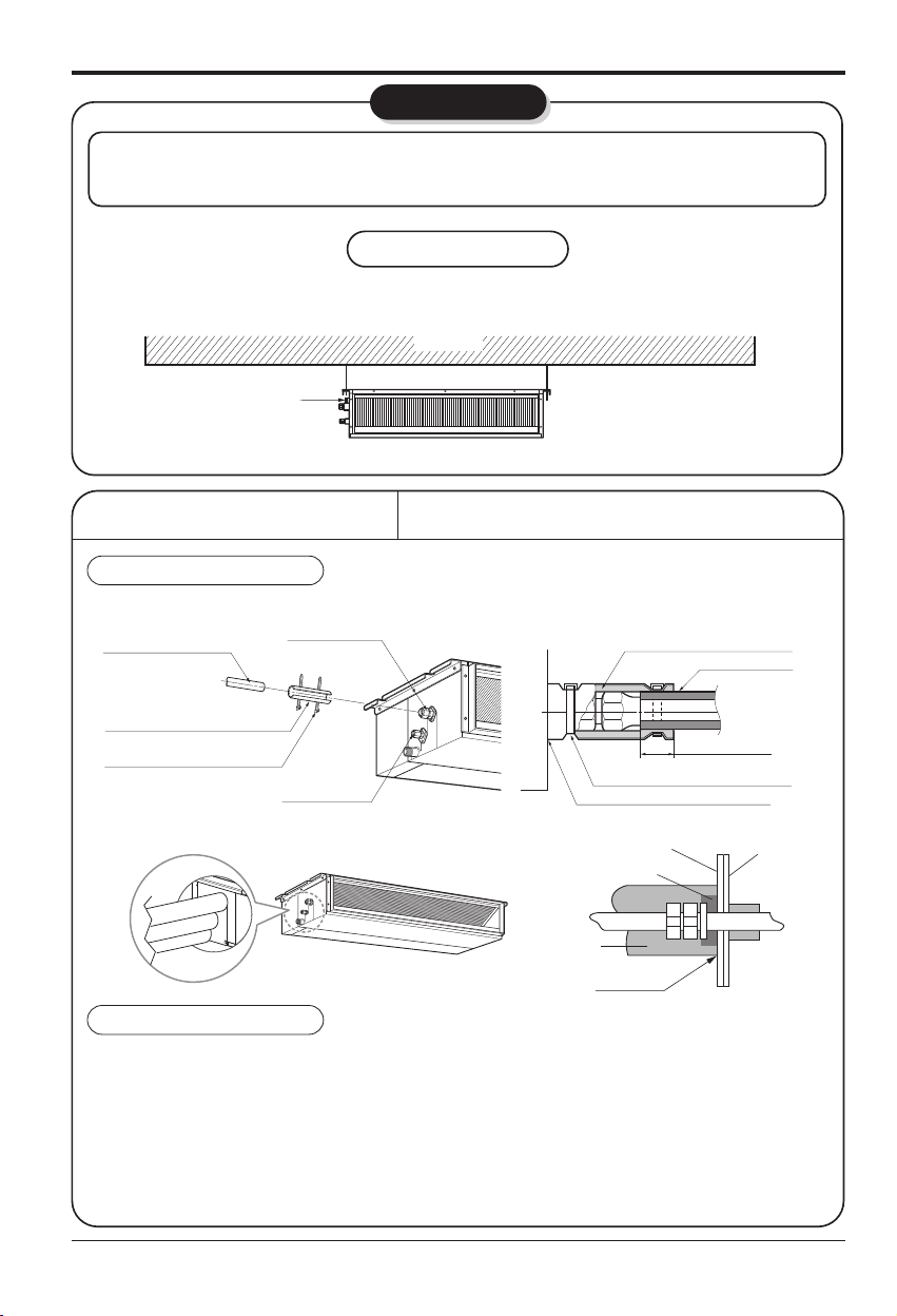
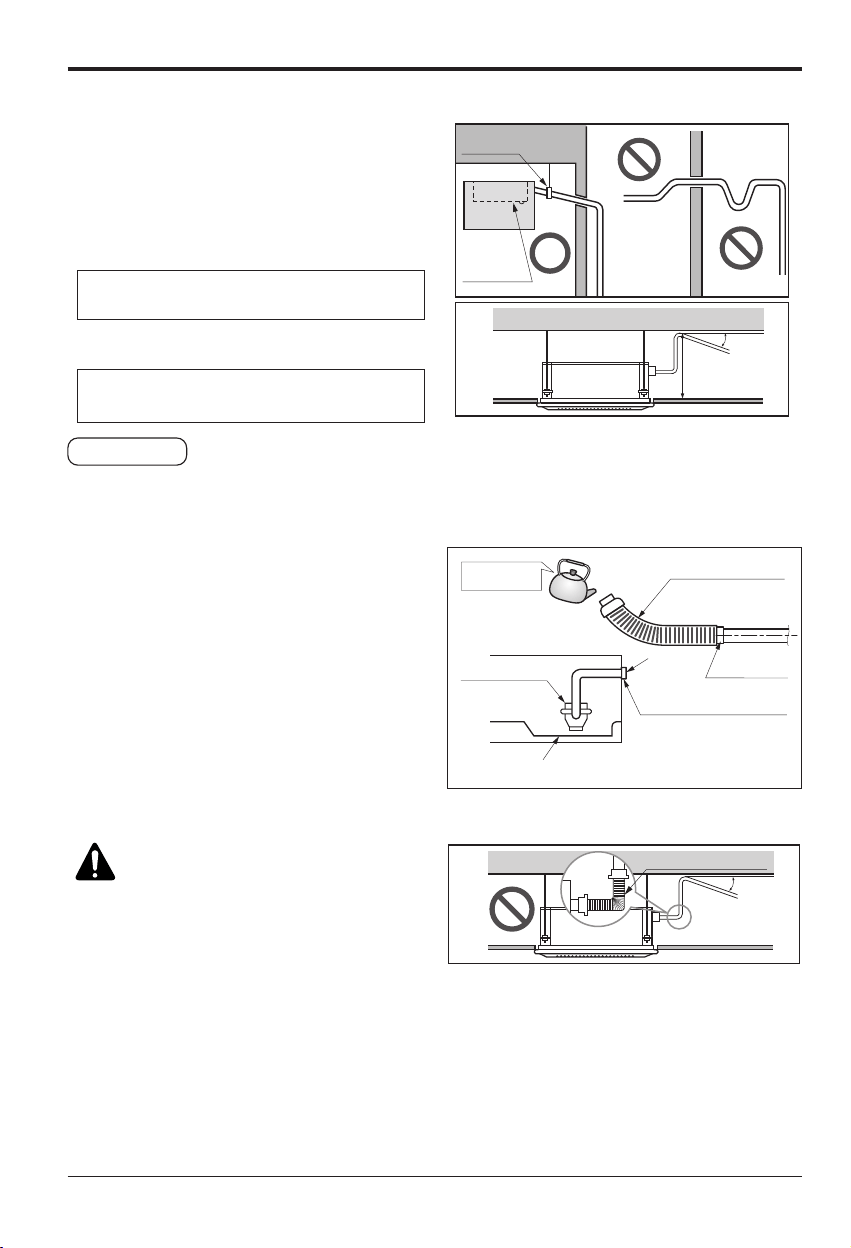
1. The drain hose should point downward for op-
timum drainage.
2. Incorrect Installation Examples:
Downward slope
Do not raise
Accumulated
drain water
Tip of drain hose
dipped in water
Air
Kinking
Water
leakage
Water
leakage
Ditch
Less than 50mm
(1 31/32 inch) gap
Water
leakage
[Standard / Standard Libero / Artcool Mirror Type]
36 Multi Air Conditioner
Installation
CAUTION : The supplied flexi-
ble drain hose should not be
curved, neither screwed. The
curved or screwed hose may
cause a leakage of water.
[Ceiling Concealed Duct/Ceiling Cassette Type]
• Drain piping must have down-slope (1/50 to 1/100): be
sure not to provide up-and-down slope to prevent rever-
sal flow.
• During drain piping connection, be careful not to exert
extra force on the drain port on the indoor unit.
• The outside diameter of the drain connection on the in-
door unit is 32mm(1 1/4 inch).
•
Be sure to install heat insulation on the drain piping.
Piping material: Polyvinyl chloride pipe inner
diometes Ø 25mm(1 inch) and pipe fittings
• Connect the main drain pipe to the exterior and
leave it provisionally until the test comes to an
end.
• Feed water to the flexible drain hose and check
the piping for leakage.
• Be sure to check the drain pump for normal op-
erating and noise when electrical wiring is com-
plete.
• When the test is complete, connect the flexible
drain hose to the drain port on the indoor unit.
The air conditioner uses a drain pump to drain water.
Use the following procedure to test the drain pump operation:
Heat insulation material: Polyethylene foam
with thickness more than 8mm(5/16 inch).
Drain test
Maintenance
drain port
Upward
routing
not allowed
Pipe clamp
Indoor unit
1/50~1/100
Flexible drain hose
MAX : 700 mm(27 9/16 inch)
Feed water
Drain Pump
Drain pan
Flexible drain hose
(accessory)
Main
drain pipe
Glue the joint
Drain
port
Drain hose connection
Use the clip (accessory)
Flexible drain hose
1/50~1/100
Flexible drain hoseFlexible drain hoseFlexible drain hose
h The figure can be changed according to model.
Installation Manual 37
ENGLISH
Installation
Attention
1. Possible drain-head height is up to
700mm(27 9/16 inch). So, it must be in-
stalled below 700mm(27 9/16 inch).
2. Keep the drain hose downward up to
1/50~1/100 inclination.
Prevent any upward flow or reverse flow in
any part.
3. 5mm(3/16 inch) or thicker formed thermal in-
sulator is provided for the drain pipe.
4. Upward routing is not allowed.
5. Be sure to check the drain pump for normal
operation and abnormal noise when electri-
cal wiring is complete.
1/50~1/100
MAX 700mm
(27 9/16 inch)
Elbow
Drain pump
Unit
Drain pipe
(Local supply)
Thermal insulator
(Local supply)
Wall
Drain hose
38 Multi Air Conditioner
Flaring Work and Connection of Piping
Flaring Work and Connection of Piping
Flaring work
Main cause of gas leakage is defect in flaring
work. Carry out correct flaring work in the fol-
lowing procedure.
1) Cut the pipes and the cable.
n Use the accessory piping kit or the pipes
purchased locally.
n Measure the distance between the indoor
and the outdoor unit.
n Cut the pipes a little longer than mea-
sured distance.
n Cut the cable 1.5m(4.9ft) longer than the
pipe length.
2) Burrs removal
n Completely remove all burrs from the cut
cross section of pipe/tube.
n Put the end of the copper tube/pipe to
downward direction as you remove burrs
in order to avoid to let burrs drop in the
tubing.
3) Putting nut on
n Remove flare nuts attached to indoor and
outdoor units, than put them on pipe/tube
having completed burr removal.
(Not possible to put them on after flaring
work)
4) Flaring work
n Carry out flaring work using flaring tool as
shown below.
Firmly hold copper tube in a bar(or die) as
indicated dimension in the table above.
5) Check
n Compare the flared work with figure.
n If flare is noted to be defective, cut off the
flared section and do flaring work again.
Copper
tube
90
Slanted Uneven Rough
Pipe
Reamer
Point down
Flare nut
Copper tube
Bar
Copper pipe
Clamp handle
Red arrow mark
Cone
Yoke
Handle
Bar
"A"
Inclined
Inside is shining without scratches.
Smooth all round
Even length
all round
Surface
damaged
Cracked Uneven
thickness
= Improper flaring =
Outside diameter A
mm inch mm inch
Ø6.35 1/4 1.1~1.3 0.04~0.05
Ø9.52 3/8 1.5~1.7 0.06~0.07
Ø12.7 1/2 1.6~1.8 0.06~0.07
Ø15.88 5/8 1.6~1.8 0.06~0.07
Ø19.05 3/4 1.9~2.1 0.07~0.08
Installation Manual 39
ENGLISH
Flaring Work and Connection of Piping
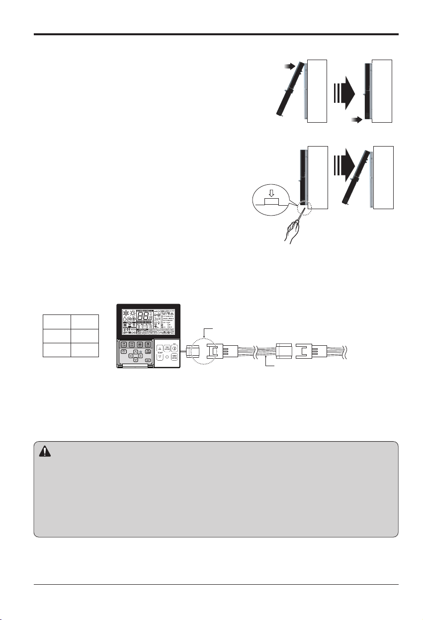
Align the center of the piping and sufficiently
tighten the flare nut by hand.
Connecting pipe order
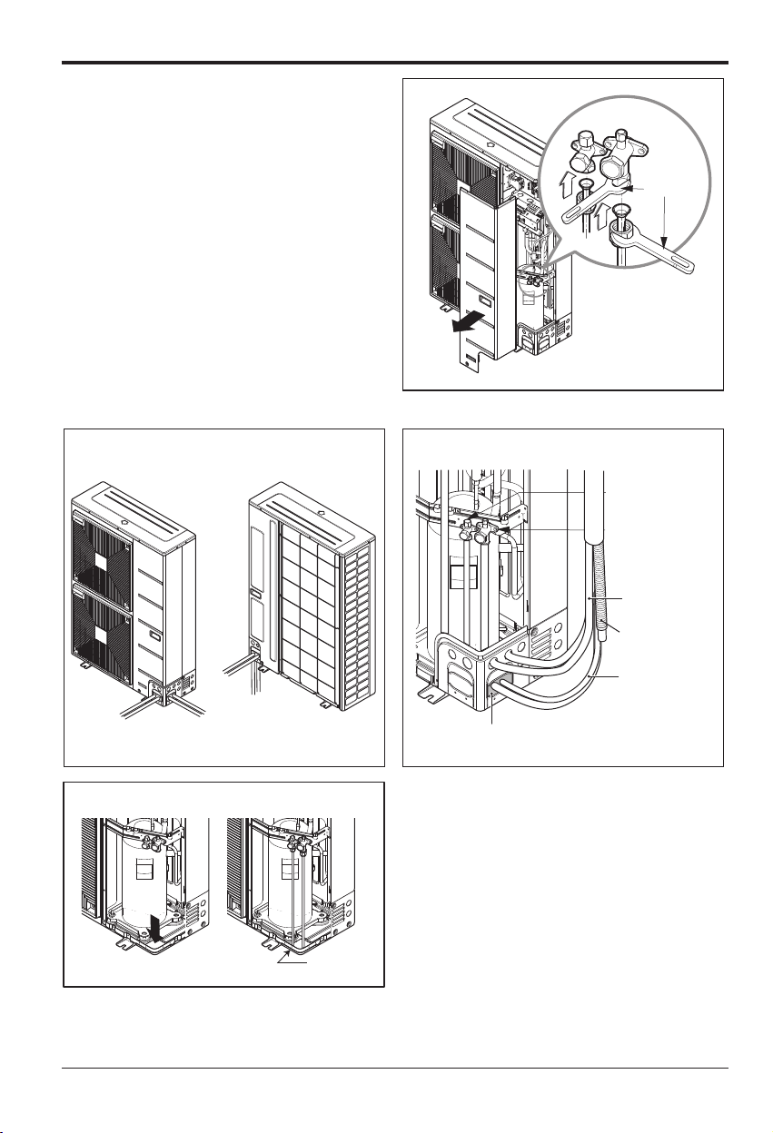
1) A~D-UNIT gas side pipe
2) A~D-UNIT liquid side pipe
Finally, tighten the flare nut with torque wrench
until the wrench clicks.
• When tightening the flare nut with torque
wrench ensure the direction for tightening fol-
lows the arrow on the wrench.
Main gas
side valve
Main liquid
side valve
Gas side piping
Liquid
side piping
A-UNIT
B-UNIT
C-UNIT
D-UNIT
Outdoor unit(36 kBtu/h class)
Connection of piping - Outdoor
(Only Indoor Units
18 kBtu/h class )
Outside diameter Torque
mm inch N. m kgf.m lbf.ft
Ø6.35 1/4 14~18 1.4~1.8 10~13
Ø9.52 3/8 34~42 3.5~4.3 25~31
Ø12.7 1/2 49~61 5.0~6.2 36~45
Ø15.88 5/8 69~82 7.0~8.4 51~60
Ø19.05 3/4 100~120 10.0~12.2 73~88
40 Multi Air Conditioner
Flaring Work and Connection of Piping
• For the units with capacity more than 48 kBtu/h,
the installation piping is connectable in four
directions.(refer to figure 1)
• When connecting in a downward direction, knock
out the knockout hole of the base pan.
(refer to figure 2)
Preventing foreign objects from entering
(Figure3)
• Plug the pipe through-holes with putty or
insulation material(procured locally)to stop up all
gaps,as shown in the figure 3.
• Insects or small animals entering the outdoor unit
may cause a short circuit in the electrical box.
Forward
Sideways
Backward
Knock-out Base pan
Downward
Gas side piping
(Bigger Dia.)
Liquid side piping
(Smaller Dia.)
Putty or insulating material
(produced locally)
Drain hose
Connecting wire
Connection pipe
<Figure 1>
<Figure 2>
<Figure 3>
Continuous
Torque
wrench
(250mm )
→
❈ When tighten the pipe, hold the haxagonal body.
Installation Manual 41
ENGLISH
Flaring Work and Connection of Piping
Facing upwards
Viewed from point A
in direction of arrow
Horizontal
plane
Gas PipeModel
PMBL5620
Ø19.05
Ø19.05
Liquid Pipe
Within +/- 10
A
Ø9.52
Ø9.52
Ø9.52
Ø19.05
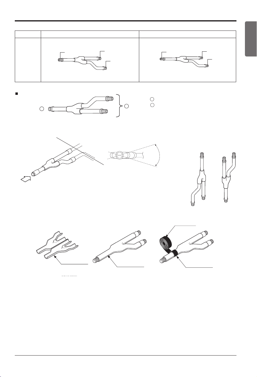
Y branch
A
B
To Outdoor Unit
[unit:mm]
To BD Unit
A
B
Liquid and gas
pipe joints
Insulator
(included with kit)
Insulator for
field piping
Tap e
(field supply)
Liquid and gas
pipe joints
Insulation
Branch
• Ensure that the branch pipes are attached horizontally or vertically (see the diagram
below.)
• Branch pipe should be insulated with the insulator in each kit.
42 Multi Air Conditioner
Flaring Work and Connection of Piping
Installation
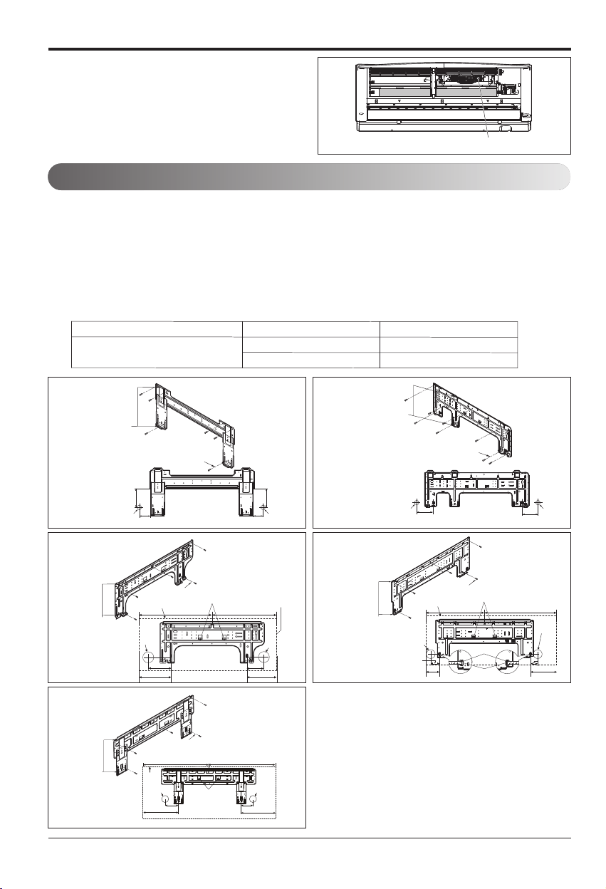
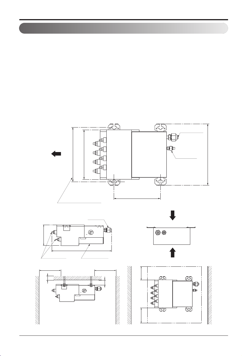
• This unit may be installed suspended from the ceiling or mounted on the wall.
• This unit may be installed horizontally , as shown in the diagram below.(Side B is facing up)
However, it may be freely installed in any direction forward or back, and to the sides.
• Be sure to leave a 600mm square opening for service and inspection as shown in the diagram
below, for both ceiling - suspended installation and wall-mounted installation.
• This unit "does not require drain treatment" as it uses internal foam treatment as low-pressure
piping insulation.
• Service direction is the side B and C
• The piping for the indoor unit may be led around in direction A
• The inclination of side B must be within ±5 degrees forward or back or to the sides.
Min 400(15 3/4)
Min 30(1 3/16)
Min 100(3 15/16)
Min 400(15 3/4)
Branch Pipe
432(17)
160(6 5/16)
Cover Control
Main Pipe
(Servicing space)
B
C
Inspection opening
Min 300(11 13/16)
Min 300(11 13/16)
298(11 23/32)
250(9 27/32)
Ø19.05(3/4)
Ø9.52(3/8)
Suspension bolt pitch.
245(9 21/32)
337(13 9/32)
A
Unit : mm(inch)
Installation Manual 43
ENGLISH
Flaring Work and Connection of Piping
:
• This unit has two different installation types:
(1) Ceiling-suspended type and (2) wall-mounted
type.
• Choose the proper installation pattern according to
the location of installation.
• The installation location for printed wiring board can
be changed.
Follow the procedure specified in the "CONNECTING
THE WIRING" section to change the location.
NOTICE
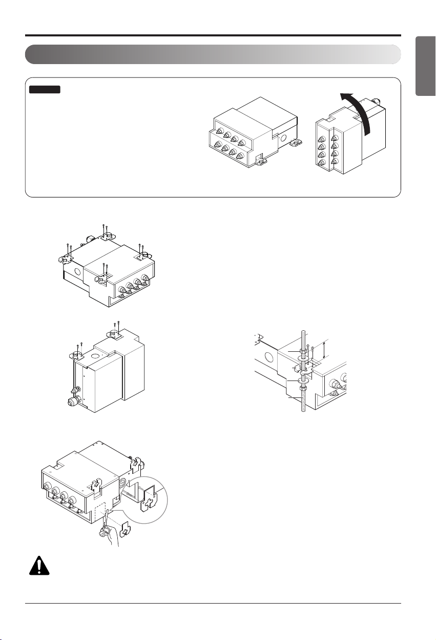
(1) Ceiling-suspended type
(2) Wall-mounted type
Screws(M5)
Screws(M5)
(locally procude)
(locally procude)
Screws(M5)
(locally procude)
PE
PE
BD unit
Six-sided Nut
Six-sided Nut
(M10 or M8)
(M10 or M8)
Six-sided Nut
(M10 or M8)
Hanger metal
Hanger metal
Hanger metal
Flat washer
Flat washer
Flat washer
Hanging bolt
Hanging bolt
Hanging bolt
(M10 or M8)
15.00
Procedure
(1) Fix the furnished hanger metal with two screws.(4 locations
in total).
(2) Using an insert-hole-in- anchor, hang the hanging bolt.
(3) Install a hexagon nut and a flat washer (locally-procured)to
the hanging bolt as shown in the figure in the left, and lift the
main unit to hang on the hanger metal.
(4) After checking with a level that the unit is level, tighten the
hexagon nut.
* The tilt of the unit should be within ±5° in front/back and
left/right.
CAUTIONS
• Once a screw-hole on the main unit has had a screw hammered in, make sure to either hammer it again
or cover it with alumium tape.(This is to prevent condensation)
• Be sure to install the unit with the ceiling-side up.
• Do not install near bedrooms. the sound of refrigerant flowing through the piping may sometimes be audible.
(1) Ceiling-suspended type (2) Wall-mountde type
Installation of The Main Unit
Procedure
(1) Fix the furnished hanger metal with two screws.
(3 locations in total).
(2) After checking with a level that the unit is level, fix the
unit with the furnished wood screws.
* The tilt of the unit should be within ±5° in front/back and
left/right.
* Block up the parts of hanger holes (2 places) by using
insulation PE after installing the hanger.
44 Multi Air Conditioner
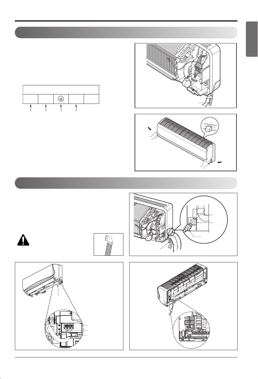
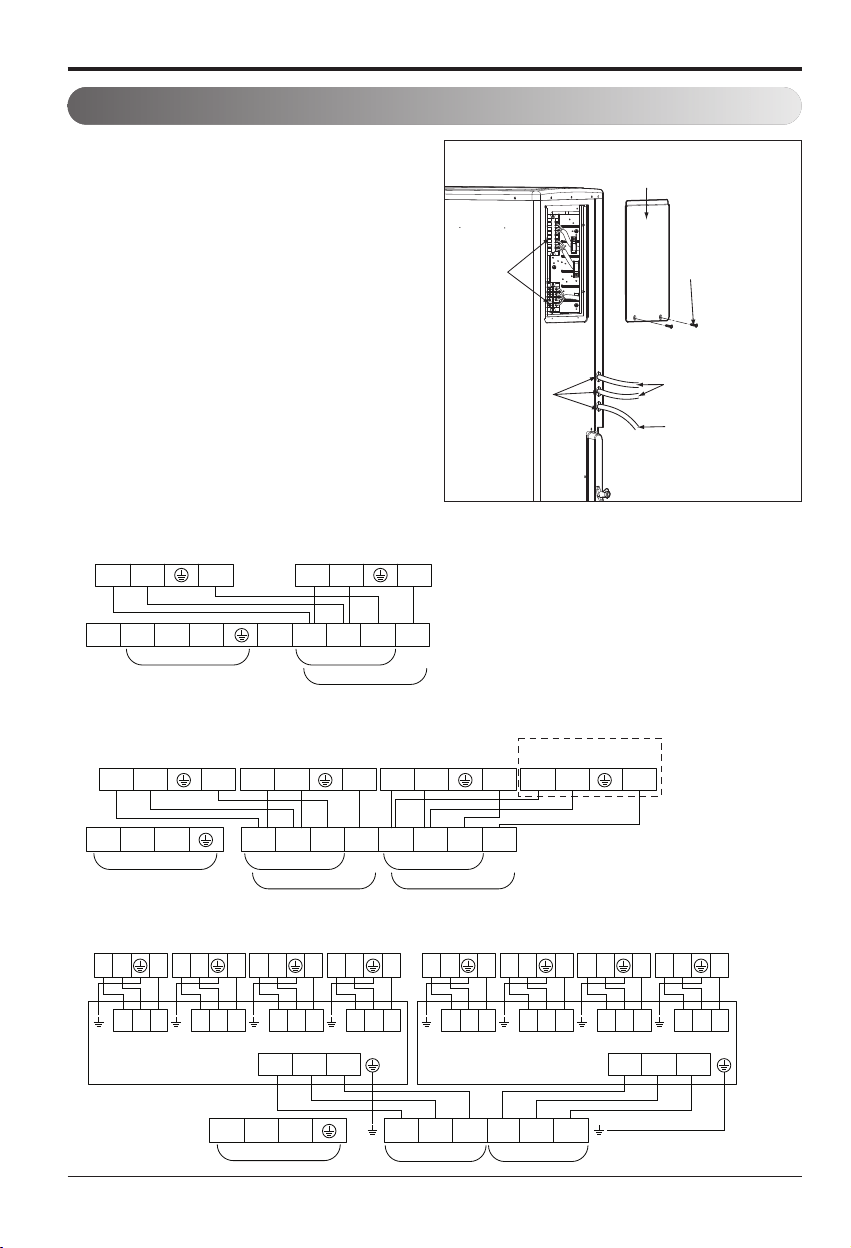
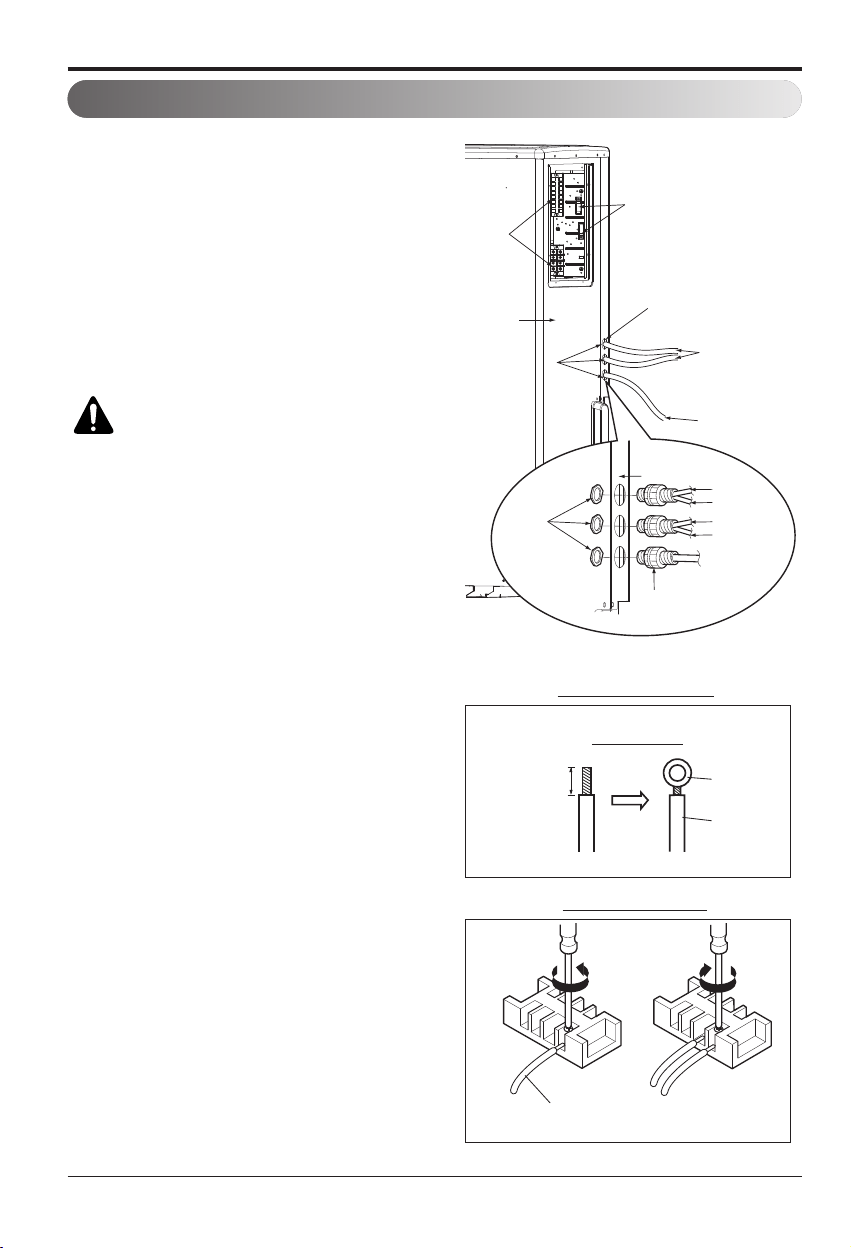
Connecting the Cable between Indoor Unit, Distributor Unit and Outdoor Unit
Connecting the Cable between Indoor Unit, Distributor Unit and Outdoor Unit
Connect the cable to the indoor unit by connecting the wires to the terminals on the control
board individually according to the outdoor unit connection. (Ensure that the color of the wires
of the outdoor unit and the terminal No. are the same as those of the indoor unit.)
The ground wire should be longer than the common wires.
The circuit diagram is not subject to change without notice.
When installing, refer to the electrical diagram behind the front panel of Indoor Unit.
The wiring for the outdoor unit can be found on the inside of the Outdoor Unit control cover.
Connect the cable to the Indoor unit.
RECOMMENDATION:
• The circuit diagram is subject to change without notice.
• Be sure to connect wires according to the wiring diagram.
• Connect the wires firmly, so that they can not be pulled out easily.
• Connect the wires according to color codes by referring to the wiring diagram.
RECOMMENDATION:
Provide a
circuit breaker between power
source and the outdoor unit as
shown below.
RECOMMENDATION:
The power cord connected to the outdoor unit should
comply with the following specifications: NRTL Recognized(for example, UL or
ETL recognized and CSA certified).
Air
Conditioner
Main power source
Circuit Breaker
Use a circuit breaker
or time delay fuse.
Line voltage
(208/230V)
GN/YL
20mm
(25/32 inch)
GN/YL
20mm
(25/32 inch)
RECOMMENDATION: When using separate wires as the power cord, please secure
separate wires in the control box panel using tie wraps to hold all wires in place.
n Power supply cable
n Connecting cable
Outdoor Unit
Capacity
(Btu/h class)
Power source
Fuse or breaker
Capacity
18k 1ø,208/230V 15A
24/36k 1ø,208/230V 25A
54k 1ø,208/230V 40A
As always, final wire selection is governed by local codes
and should be installed by a licensed professional contrac-
tor.
The power connecting cable between the outdoor and in-
door units must comply with the following specifications:
NRTL Recognized (for example, UL or ETL recognized and
CSA certified).
AWG 18-4 is the minimum recommended wire size,
however, the selected conductors must comply with local
codes and be suitable for installation in wet locations.
The minimum recommended wire size
18kBtu/h AWG 14-3
24/36kBtu/h AWG 12-3
54kBtu/h AWG 8-3
Installation Manual 45
ENGLISH
Connecting the Cable between Indoor Unit, Distributor Unit and Outdoor Unit
(1) Remove the control cover. Loosen the two
screws, and slide the cover in the direction
of the arrow.
(2) Pull out connection cable through conduit.
After conduit to the panel, fix nut to the
opposite side of panel. Pass the connection
cabel through the hole.
(3)
Perform wiring with reference the wiring diagram
on a control cover of outdoor unit. Allow 300
mm(11 13/16 inch) for the pulling-out section of
harness. Fix the wires completely with wire
clamps(4 locations).
(4) Put in the cover in the direction of the arrow
then tighten the screws.
• Connect refrigerant pipes and connection wires to the appropriate ports maked with matching
alphabets (A, B and C) on this unit.
• Follow the instructions on the wiring nameplate to connect the connection wires of indoor/outdoor
units to terminal board numbers.(1, 2 and 3) Always fix each ground wire separately with a ground
screw.(See the figure below.)
• After completing the wiring, fix the outer coating of wires securely with wire clamps. The wire
clamp on indoor unit side is furnished. Follow the procedure below to install.
• Refer to the circuit diagram on the control cover inside outdoor unit.
:
The terminal board numbers are arranged from top to bottom in order of 1, 2 and 3.
NOTICE
Warning
Do not use tapped wires,
stand wires, extensioncords,
or starbust connections, as
they may cause
overtheating, electrical
shock, or fire.
A room
B room
C room
A
B
C
CN-PWR
Connection wire for indoor units
(AWG 18-4)
Connection wire for outdoor units
(AWG 16-4)
Lock nut (field supply)
Lock nut (field supply)Lock nut (field supply)
Conduit (field supply)
Lock nut (field supply)
Lock nut (field supply)
In Case of 3 rooms
Connect the cable to the Distributor unit.
46 Multi Air Conditioner
Connecting the Cable between Indoor Unit, Distributor Unit and Outdoor Unit
Connect the cable to the Outdoor unit.
1. Remove the control cover from the unit by loos-
ening the screw.
Connect the wires to the terminals on the control
board individually as the following.
2. Secure the cable onto the control board with the
holder (clamper).
3. Re-attach the cover control to the original posi-
tion using the screws.
1(L1) 2(L2) 3 1(L1) 2(L2) 3
Indoor Unit Terminal Block
A Unit
Indoor Unit Terminal Block
B Unit
L1 L2 1(L1) 2(L2) 3(A) 3(B)
POWER SUPPLY A UNIT
B UNIT
C UNIT
D UNIT
1(L1) 2(L2) 3 1(L1) 2(L2) 3
A Unit B Unit
1(L1) 2(L2) 3(B) 3(A) 1(L1) 2(L2) 3(C) 3(D)
POWER SUPPLY A UNIT
B UNIT
Indoor Unit Terminal Block
Indoor Unit Terminal Block
A Unit
Indoor Unit Terminal Block
B Unit
Indoor Unit Terminal Block
C Unit
Indoor Unit Terminal Block
D Unit
Indoor Unit Terminal Block
E Unit
Indoor Unit Terminal Block
F Unit
Indoor Unit Terminal Block
G Unit
Indoor Unit Terminal Block
H Unit
Indoor Unit Terminal Block
1(L1) 2(L2) 3
C Unit
Indoor Unit Terminal Block
1(L1) 2(L2) 3
D Unit
Indoor Unit Terminal Block
L1 L2
36k Only
18kBtu/h class
24/36 kBtu/h class
54 kBtu/h class
BD Unit (A)
BD Unit (A)
A Room B Room C Room D Room A Room B Room C Room D Room
BD Unit (B)
BD Unit (B)
1(L1) 2(L2) 3(A) 1(L1) 2(L2) 3(B)
POWER SUPPLY
L1 L2
L(L1) N(L2) S L(L1) N(L2) S
1(L1) 2(L2) 3
L(L1) N(L2) S
1(L1) 2(L2) 3
L(L1) N(L2) S
1(L1) 2(L2) 3
L(L1) N(L2) S
1(L1) 2(L2) 3
L(L1) N(L2) S
1(L1) 2(L2) 3
L(L1) N(L2) S
1(L1) 2(L2) 3
L(L1) N(L2) S
1(L1) 2(L2) 3
L(L1) N(L2) S
1(L1) 2(L2) 3
L(L1) N(L2) S
Outdoor unit
Terminal
block
Conduit hole
Power supply
cable
Connecting cable
(to the indoor unit)
Screw
Cover control
Installation Manual 47
ENGLISH
Connecting the Cable between Indoor Unit, Distributor Unit and Outdoor Unit
:
1. Use connection cable NRTL(UL, ETL, CAS…) listed and stranded copper(4) THHN conductors,
sunlight (UV) resistant ROHS compliant PVC jacket 600V direct burial listed, approved for wet
conditions. Temperature rated for –20℃(-4℉) to 90℃(194℉). And this cable should be enclosed
in conduit.
WARNING:
• Be sure to comply with local and national codes while running the wire from the indoor unit to the
outdoor unit(size of wire and wiring method, etc).
• Every wire must be connected firmly.
• No wire should be allowed to touch refrigerant tubing, the compressor or any moving parts.
• The communication wirings of air conditioner should be separate and isolated from external de-
vice’s electric wiring such as computers, elevator, radio & Television broadcasting facilities, as
well as medical imaging offices.
NOTICE
48 Multi Air Conditioner
Connecting the Cable between Indoor Unit, Distributor Unit and Outdoor Unit
(1) Remove the side panel and knockouts of conduit
panel. (for low voltage line)
(2) Pull out connection cable through conduit.
(3) After conduit to the panel, fix nut to the opposite
side of panel.
(4) Pass the connection cabel through the hole.
(5) Properly connect the cable on the terminal block.
(6) Fix the connection cable with cord clamp pro-
vided on the unit not to have strain at the ter-
minal when the connection cable is pulled
outside up to a 35 pound weight
WARNING: Loose wiring may cause
the terminal to overheat or result in
unit malfunction. A fire hazard may
also exist. Therefore, be sure all
wiring is tightly connected.
When connecting each power wire to the corre-
sponding terminal, follow instructions "How to
connect wiring to the terminals" and fasten the
wire tightly with the fixing screw of the terminal
plate.
How to connect wiring to the terminals
◼ For strand wiring
(1) Cut the wire end with a wire cutter or wire-cut-
ting pliers, then strip the insulation to expose
the strand wiring about 10 mm(3/8").
(2) Using a screwdriver, remove the terminal
screw(s) on the terminal plate.
(3) Using a round terminal fastener or pliers, se-
curely clamp each stripped wire end with a
round terminal.
(4) Position the round terminal wire, and replace
and tighten the terminal screw using a screw-
driver.
Connection method of the connecting cable(Example)
Power supply cable
Connecting Cable
Strip 10 mm(3/8")
Round
terminal
Power wire
(Ground wire)
Connecting cable
Loosening the
terminal block
screw
Fastening the
wire tightly
Strand wire
Terminal
block
Side panel
Cord clamp
Conduit hole
Power supply cable
(1Ø, 208/230V)
Connecting cable
(1Ø, 208/230V)
Taping
(for sealing)
Lock nut
(field supply)
Conduit
(field supply)
Conduit panel
Indoor Unit A
Indoor Unit B
Indoor Unit C
Indoor Unit D
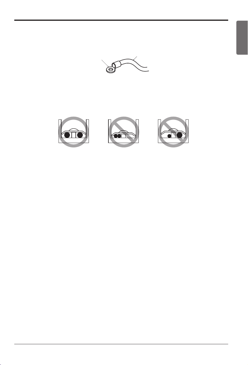
Installation Manual 49
ENGLISH
Connecting the Cable between Indoor Unit, Distributor Unit and Outdoor Unit
• For wiring, use the designated power wire and connect firmly, then secure to prevent outside pres-
sure being exerted on the terminal block.
• Use an appropriate screwdriver for tightening the terinal screws. A screwdriver with a small head
will strip the head and make proper tighterning impossible.
• Over-tightening the terminal screws may break them.
When none are available, follow the instructions below.
• Do not connect wiring of different thicknesses to the power terminal block. (Slack in the power
wiring may cause abnormal heat.)
• When connecting wiring which is the same thickness, do as shown in the figure below.
u
Precautions when laying power and ground wiring
Round pressure terminal
Power wire(Ground wire)
Use round pressure terminals for connections to the power terminal block.
When laying ground wiring, you must use round pressure terminals.
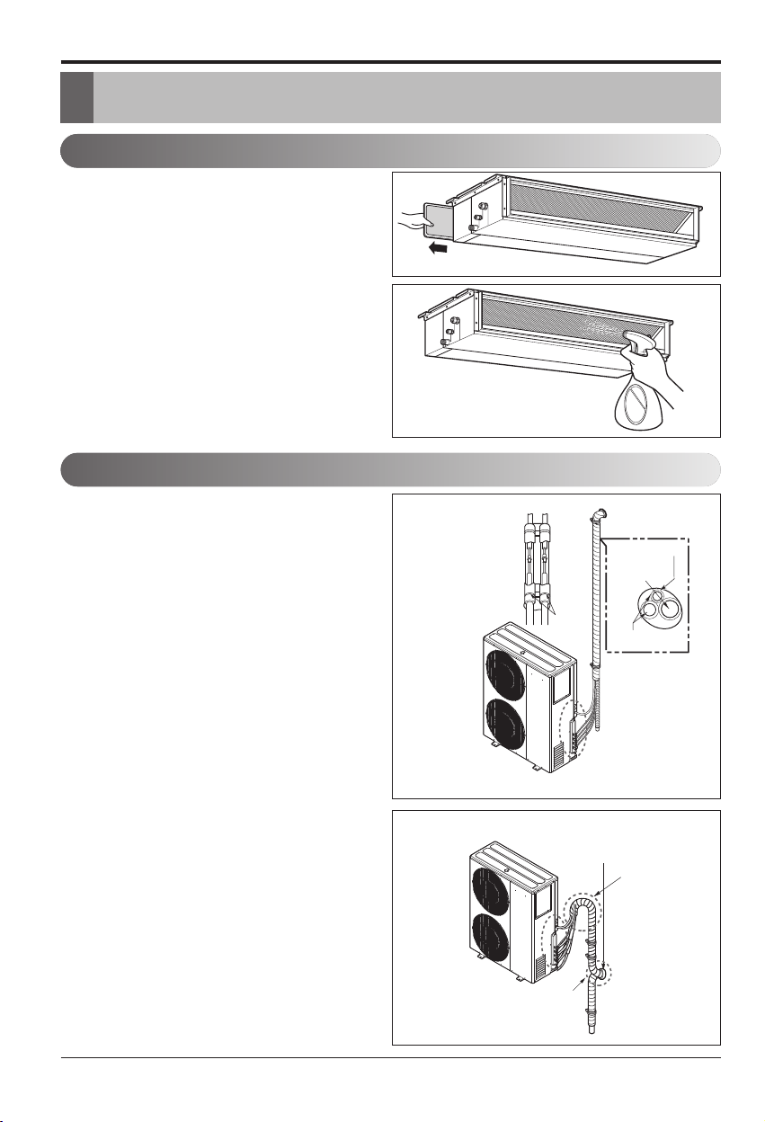
50 Multi Air Conditioner
Checking the Drainage, Insulating the Pipe and Special Piping Applications
Insulating the Pipe and Special Piping Applications
Insulate the piping by wrapping the
connecting portion of the indoor unit
with insulation material and secure it
with two kinds of vinyl tape.
• If you want to connect an additional drain hose,
the end of the drain outlet should be routed
above the ground. Secure the drain hose ap-
propriately.
In cases where the outdoor unit is in-
stalled below the indoor unit perform
the following:
1. Tape the piping, drain hose and connecting
cable from down to up.
2. Secure the taped piping along the exterior
wall using saddle or equivalent.
In cases where the Outdoor unit is
installed above the Indoor unit per-
form the following.
1. Tape the piping and connecting cable from
down to up.
2. Secure the taped piping along the exterior
wall. Form a trap to prevent water entering
the room.
3. Secure the piping onto the wall using a saddle
or equivalent.
Plastic
band
Taping
Drain hose
Pipings
Seal a small
opening around
the pipings with
gum type sealant.
Seal a small opening
around the pipings
with gum type sealant.
Trap
Trap
Checking the Drainage, Insulating the Pipe and Special Piping Applications
Checking the drainage
1. Remove the Air Filter.
2. Check the drainage.
• Spray one or two glasses of water upon the
evaporator.
• Ensure that water flows drain hose of indoor
unit without any leakage.
h The figure can be changed according to model.
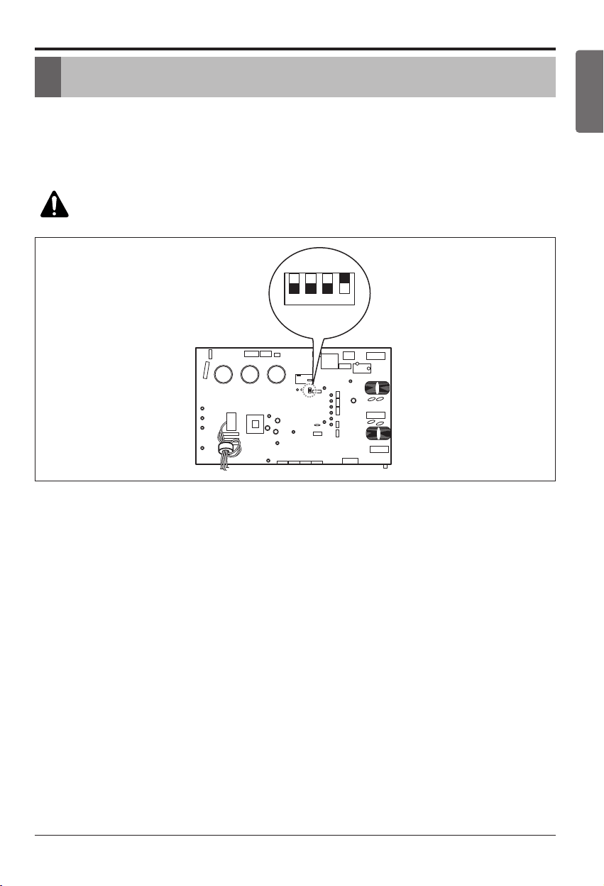
Installation Manual 51
ENGLISH
Long Pipe Setting
Long Pipe Setting
1
SW01N
234
1. Open the top cover of outdoor unit.
2. Select one of the two selectable modes as follows.
3. Set the Zone as shown in Fig.
4. Close the top cover and check whether the product works normally.
WARNING: Do not open the top cover or Set the pipe length when operat-
ing the product.
18/24/36 kBtu/h class
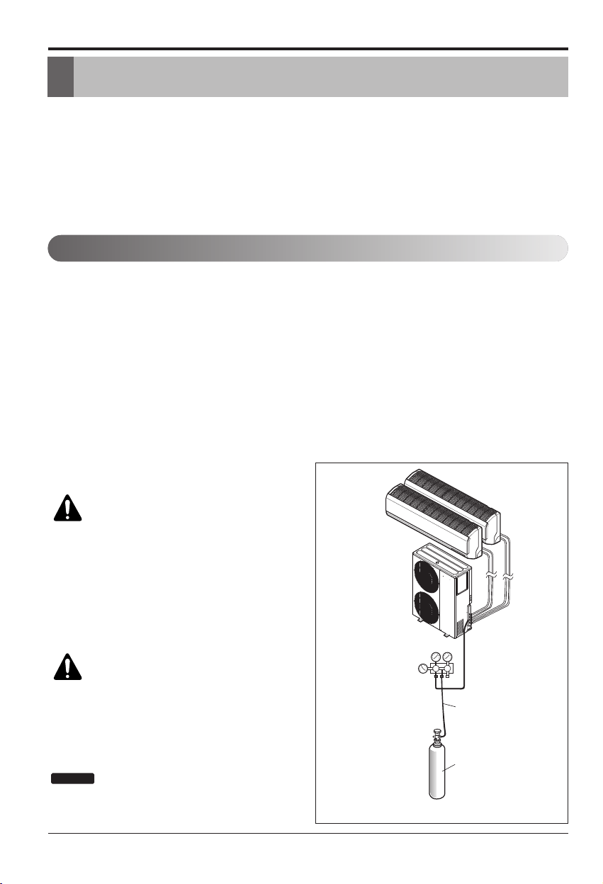
52 Multi Air Conditioner
Air Purging and Evacuation
Air Purging and Evacuation
Air and moisture remaining in the refrigerant system have undesirable effects as indicated below.
1. Pressure in the system rises.
2. Operating current rises.
3. Cooling(or heating) efficiency drops.
4. Moisture in the refrigerant circuit may freeze and block capillary tubing.
5. Water may lead to corrosion of parts in the refrigeration system.
Therefore, the indoor/outdoor unit and connecting tube must be checked for leaks, and vacuumed
to remove incondensible gas and moisture in the system.
Preparation
• Check that each tube(both liquid and gas side
tubes) between the indoor and outdoor units have
been properly connected and all wiring for the test
run has been completed. Remove the service
valve caps from both the gas and the liquid sides
on the outdoor unit. Check that both the liquid and
the gas side service valves on the outdoor unit are
kept closed at this stage.
Leakage test
• Connect the manifold valve(with pressure gauges)
and dry nitrogen gas cylinder to this service port
with charge hoses.
CAUTION: Be sure to use a
manifold valve for leak testing.
The high side manifold valve must
always be kept closed.
• Pressurize the system to no more than 550
P.S.I.G. with dry nitrogen gas and close the
cylinder valve when the gauge reading
reached 550 P.S.I.G. Next, test for leaks with
liquid soap.
CAUTION:
To avoid nitrogen enter-
ing the refrigerant system in a liquid
state, the top of the cylinder must be higher
than its bottom when you pressurize the
system. Usually, the cylinder is used in a
vertical standing position.
:
Leakage testing shoud be done for
each indoor unit connection set, separately.
1. Do a leakage test of all joints of the
tubing(both indoor and outdoor) and both gas
and liquid side service valves with soap bub-
bles.
Bubbles indicate a leak. Be sure to wipe off
the soap with a clean cloth.
2. After the system is found to be free of leaks,
relieve the nitrogen pressure by loosening the
charge hose connector at the nitrogen cylin-
der. When the system pressure is reduced to
normal, disconnect the hose from the cylinder.
NOTICE
Leak Checking
Charge hose
Nitrogen gas
cylinder(in vertical
standing position)
Indoor unit
Outdoor unit
Lo Hi
Manifold valve
Pressure
gauge
h The figure can be changed according to model.
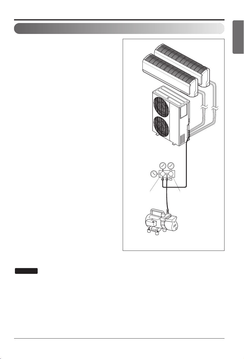
Installation Manual 53
ENGLISH
Air Purging and Evacuation
1. Connect the charge hose end described in
the preceding steps to the vacuum pump to
evacuate the tubing and indoor unit.
Confirm the "Lo" knob of the manifold valve is
open. Then, run the vacuum pump.
The operation time for evacuation varies with
tubing length and capacity of the pump.
[Each Room] The vacuum pump must be op-
erated less than 0.8torr of the gage pressure.
2. When the desired vacuum is reached, close
the "Lo" knob of the manifold valve and stop
the vacuum pump.
Finishing the job
1. With a service valve wrench, turn the valve
stem of liquid side valve counter-clockwise to
fully open the valve.
2. Turn the valve stem of gas side valve counter-
clockwise to fully open the valve.
3. Loosen the charge hose connected to the gas
side service port slightly to release the pres-
sure, then remove the hose.
4. Replace the flare nut and its bonnet on the
gas side service port and fasten the flare nut
securely with an adjustable wrench. This
process is very important to prevent leakage
from the system.
5. Replace the valve caps at both gas and liquid
side service valves and fasten them tight.
This completes air purging with a vacuum pump.
The air conditioner is now ready for test running.
: Repeat evacuation procedure for each
indoor unit.
NOTICE
Indoor unit
Outdoor unit
Lo Hi
Manifold valve
Vacuum pump
Pressure
gauge
Open
Close
Evacuation
h The figure can be changed according to model.
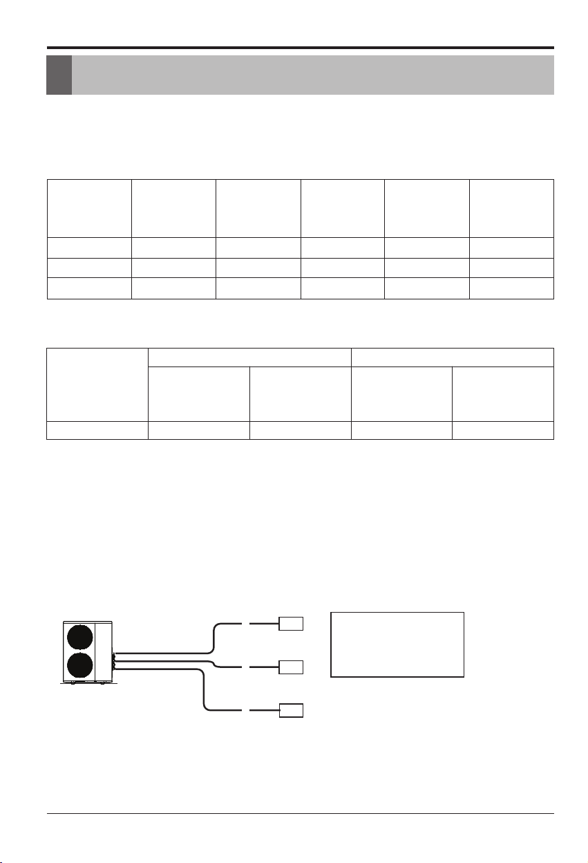
54 Multi Air Conditioner
Charging
Important:
If you are ever uncertain of the unit charge, reclaim, evacuate and weigh in the correct charge using
the charge amount specified on the Unit`s specification label.
Multiple Piping Models
Additional charge(oz ) = (Total Installation Piping Length-Standard Total Piping Length) x 0.22
Charging
n If installed total piping length is more than standard total length, additional refrigerant charging is
necessary.
Below standard total piping length, additional refrigerant charging is not required.
18k 50(164) 25(82) 3(9.8) 20(0.22) 15(49.2)
24k 75(246) 25(82) 3(9.8) 20(0.22) 22.5(74)
36k 75(246) 25(82) 3(9.8) 20(0.22) 30(98.4)
Outdoor Unit Ca-
pacity (Btu/h class)
Max total length of all
pipes (A+B)/(A+B+C)/
(A+B+C+D)
Max length of each
pipe (A/B/C/D)
Min length of each
pipe (A/B/C/D)
Additional Refrigerant
Unit : g/m (oz/ft)
Standard Total Piping
Length (No Add`l re-
frigerant)
Unit:m(ft)
Unit:m(ft)
Each branch pipe
a=82ft
b=16ft
c=49ft
Additional Charge
= {(82+16+49)-98.4} x 0.22 = 10.69 oz
A
a
b
c
9k
9k
9k
Ex) A4UW363FA2
Multiple Piping Models
Distributor Type Model
Outdoor Unit
Capacity
(Btu/h class)
Main Piping Length Branch Piping Length
Standard Length
Additional
Refrigerant
Unit : g/m (oz/ft)
Standard
Length
Additional
Refrigerant
Unit : g/m (oz/ft)
54k 5(16.4) 50(0.55) 5(16.4) 20(0.22)
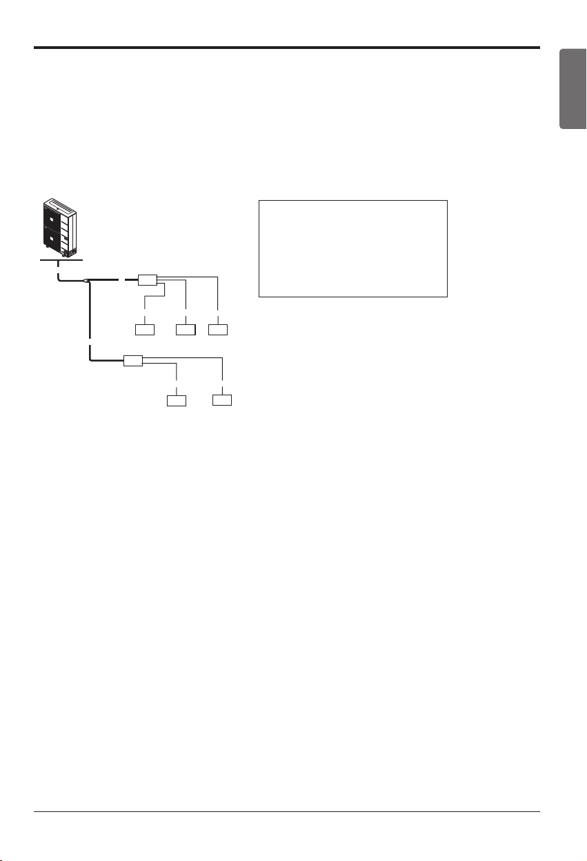
Installation Manual 55
ENGLISH
Charging
h If the total additional charge value after calculation comes out to be negative, then do not consider
additional charge.
A
Ex) A8UW54GFA0
A
B
C
abc
18k 9k 9k
d
e
9k
18k
Distributor type Models
Additional charge (oz) = (( Total Main piping Length - Main Standard Length ) x 0.55
+ (A Room Branch Length – Standard Length ) x 0.22
+ (B Room Branch Length – Standard Length ) x 0.22
+ (C Room Branch Length – Standard Length ) x 0.22 +.. )
- CF(Correction Factor) x 3.53
h CF = Max. number of connectable indoor unit – Total number of connected indoor unit
• Total main pipe(A+B+C)=98ft
• Each branch pipe
a=33ft
b=26ft
c=16.4ft
d=10ft
e=33ft
v Additional Charge
= ((98-16.4)×0.55 + (33-16.4)×0.22
+ (26-16.4)×0.22 + (16.4-16.4)×0.22
+ (10-16.4)×0.22 + (33-16.4)×0.22)
- (8-5)×3.53 = 42.3oz
56 Multi Air Conditioner
Max Combination Capacity
Max Combination Capacity
Multi Piping Type
Capacity
(kBtu/h)
Max Room No.
Combination Indoor Capacity
(kBtu/h)
Max Combination Capacity
(kBtu/h)
18 2 7,9,12,15 24
24 3 7,9,12,15,18,24 33
36 4 7,9,12,15,18,24 48
Distributor Type
Phase
Capacity
(kBtu/h)
Max Room No.
Combination Indoor Capacity
(kBtu/h)
Combination Capacity Range
(kBtu/h)
1Ø 54 8 7,9,12,15,18,24,36 24~73
The combination of indoor unit is to be decided that the sum of indoor unit capacity index must be
smaller than the maximum combination capacity of outdoor unit. We recommend to calculate indoor
unit capacity like below.
If you do not follow our recommendation, it will have some problems in low ambient condition i.e.
some indoor unit will not be able to heat very well in heating mode.
CALCULATION METHOD FOR THE CONNECTABLE TOTAL CAPACITY OF INDOOR UNIT
Sum up the capacity of all indoor unit, but high static duct type indoor unit capacity weights 1.3 times
Ex) 1. Outdoor unit : A8UW54GFA0(LMU540HV)(connectable maximum capacity is 73kBtu)
Indoor unit:
AMNW24GBGA0[LMHN240HV], AMNW36GBGA0[LMNH360HV]
(24+36) x 1.3 = 60 x 1.3 = 78kBtu : this combination has a some problem
2. Out door unit: A8UW54GFA0(LMU540HV)
Indoor unit:
AMNW24GBGA0[LMHN240HV], AMNW24GBGA0[LMNH240HV]
(24+24) x 1.3 = 48 x 1.3 = 62.4kBtu : this combination can be ok


