Loading ...
Loading ...
Loading ...
12
7b
DISCARD PACKAGING
GAS
ON
GAS
ON
1
2
Fibre washer
Floating nut
Elbow (½” BSP external thread)
Foam Tape
Adhesive side
20 mm
50 mm
+50 mm
NG
ALL Models
Make sure the connection point will be accessible with the cooktop installed.
To enable the gas supply to be readily shut o by the customer, make sure the connection
is tted with an isolating valve close to the cooktop.
Adjust to obtain a test point
pressure of 1 kPa with all the
burners operating at
highest setting.
Ensure the hose is long enough to allow for removal of cooktop for servicing.
Make sure the connector is located as shown in step 5 CLEARANCE DIMENSIONS.
The hose assembly must be AS/NZS 1869 Class B or D certied, with an Rp ½” (ISO 7‐1) female thread connection.
The hose assembly must be as short as practicable and comply with relevant AS 5601/NZS 5261 requirements.
The hose must not be kinked, subjected to abrasion or permanently deformed.
The hose must not be near or in contact with any hot surfaces
(e.g. base of metal hotlplate, ue, or chassis of underbench oven etc.)
If connecting the gas with a exible hose:
LPG
recessed to 50 mm
check all connections
Make sure the supply pressure
is regulated to 2.75 kPa, with
all the burners operating at
highest setting.
If converting to LPG, see 16 'Converting to a dierent gas type'
To check that the ignition system operates correctly, light each burner by itself, then all burners in combination.
Check for a well‐dened blue ame without any yellow tipping.
If any abnormality is evident, check that the components of the burner assembly are located properly
If proper operation cannot be obtained, contact your nearest F&P Authorised Service Centre.
The cooktop must not be used by the customer until proper operation has been achieved.
yellow tiplifting o
good ame
Arrow
Recycle responsibly
Model may vary from illustrations shown
8b
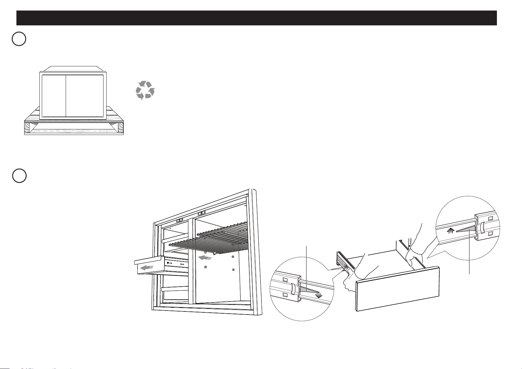
REMOVE ALL DRAWERS and SHELVES TO ACCESS SCREW HOLE LOCATIONS
Inspect the product(s) to verify that there is no shipping damage.
If any damage is detected, call the shipper and initiate a damage claim.
DCS by Fisher & Paykel is not responsible for shipping damage.
NOTE: Do not discard any packing material until the unit has been inspected.
Operate the drawers and shelves to be sure they glide smoothly.
Examine the fronts to be sure there are no dents or scratches or discoloring.
Exercise caution if fully opening the pantry doors. The outer frame
could mark the door fronts.
To remove the drawer(s)
1
Remove the drawers by pulling them
out until the slider latch is visible.
2
Carefully push the latch down on the
left side, while lifting up the latch on
the right side.
3
Pull the drawer out of the frame.
Note: to prevent damage to surfaces, place
the drawers on a stable surface on a
protective towel or table cloth.
Left Slider latch
Right Slider latch
INSTALLING PANTRY UNIT
CORNER INSTALLATIONS
Loading ...
Loading ...
Loading ...