Scoan
®

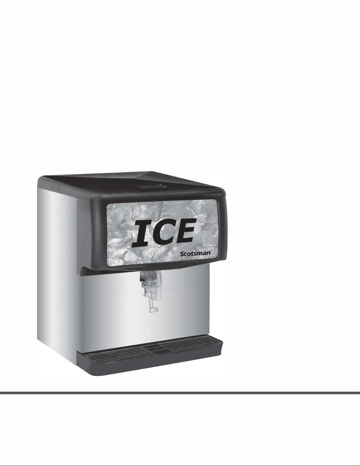
IN TRO DUC TION
This service manual is intended as a reference for
the installer, user, and service agent of this
Scotsman ice dispenser. It includes the necessary
information to install, start up, operate, clean and
maintain this unit.
This manual contains important information, read it before beginning installation or operation.
Keep it for future reference.
ID150, ID200, ID250
May 2002
Page 1
Table of Contents
IN TRO DUC TION ······································ Page 1
SPEC I FI CA TIONS ······································ Page 2
FOR THE IN STALLER ···································· Page 3
IN STAL LA TION ······································· Page 4
WA TER GLASS FILLER KIT ································· Page 5
WA TER GLASS KIT - CON TINUED ····························· Page 6
ICE DI VERTER KIT ····································· Page 7
ICE DI VERTER KIT ····································· Page 8
INI TIAL START UP ····································· Page 9
GATE RESTRICTOR PLATE ································· Page 10
CLEANING AND SAN I TIZING ································ Page 11
CLEANING AND SAN I TIZING ································ Page 12
TROU BLE SHOOTING ···································· Page 13

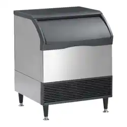
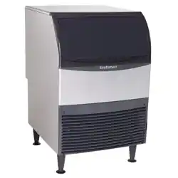
SPEC I FI CA TIONS
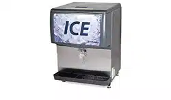
The ID ice dispenser is a machine that stores
manually filled ice in an insulated, sanitary
container; upon demand it dispenses that ice into a
cup or glass.
NOTE: This ice stand is designed to dispense
cubed ice and *Nugget Ice. Flaked ice will not
work.
Scotsman reserves the right to make design
changes and/or improvements at any time.
Specifications and designs are subject to change
without notice.
*Additional
Kits required
ID150, ID200, ID250
June 2016
Page 2
Model Dimensions
w” x d” x h”
Basic
Electrical
Hopper
Capacity
Amps Cup
Clearance
Dispense
Actuation
Method
ID150B-1A 22 x 30 x 35 5/8 115/60/1 150 lb 3.0 10” Lever
ID200B-1A 30 x 30 x 35 5/8 115/60/1 200 lb 3.5 10” Lever
ID250B-1A 30 x 30 x 39 5/8 115/60/1 250 lb 3.5 10” Lever
Note: Dispenser height includes cover (1 5/8”).
Options: Water glass filler kit (KWGFID). Diverter kit for Scotsman Nugget Ice (KNUGDIV)
Adapters: Adapters are required for placing an ice machine onto the top of this dispenser. See sales
literature for adapter information.

FOR THE IN STALLER
This ice dispenser has been specifically designed
to provide protection against personal injury and
eliminates contamination of ice. To ensure
continued protection and sanitation, observe the
following:
· ALWAYS: disconnect power to the dispenser
before servicing or cleaning.
· NEVER: place hands inside of hopper or gate
area without disconnecting power to the
dispenser.
· Agitator rotation occurs automatically when
dispenser is energized!
· ALWAYS: be sure the removable lid is properly
installed to prevent unauthorized access to the
hopper interior and possible contamination of
the ice.
· ALWAYS: be sure the upper and lower front
panels are securely fastened.
· ALWAYS: keep area around the dispenser
clean of ice cubes.
· CAUTION: Dispenser cannot be used with
crushed or flaked ice.
Use of bagged ice, which has frozen into large
chunks, can void warranty.
The dispenser agitator is not designed to be an ice
crusher. Use of large chunks of ice which “jam up”
inside the hopper will cause failure of the agitator
motor and damage to the hopper. If bagged ice is
used, it must be carefully and completely broken
into small, cube-sized pieces before filling into the
dispenser hopper.
DESCRIPTION
Designed to be manually filled with ice from any
remote ice-making source, these dispensers will
dispense cubes (up to 1-1/4” in size), cubelets and
hard-chipped or cracked ice.
IMPORTANT: For dispensing compressed or
extruded style ice, an Ice Diverter Kit must be
installed on the dispensers (see ICE DIVERTER
KIT (KNUGDIV) in INSTALLATION
INSTRUCTIONS section of this manual. The Ice
Diverter Kit is part of the KBT46 adapter.
ID150, ID200, ID250
May 2002
Page 3

IN STAL LA TION
1. Locate the ice dispenser on the counter. Allow
vertical clearance above unit for the removal of the
cover, and for pouring ice into the hopper.
2. Plan the unit drain. A 1” I.D. drain tube is
required for draining. Routing is either thru the
back or base. Sufficient fittings are included with
the unit to install in most cases.
3. In order to comply with National Sanitation
Foundation (NSF) requirements, this unit must be
either elevated above the counter top sufficiently to
provide space for cleaning under the unit or sealed
to the counter top.
Elevating the unit may be accomplished by using
the legs. They will screw into threaded holes in the
base of the unit.
Note: Before installing legs the plastic plugs
must be removed.
IMPORTANT:
It is the responsibility of the Installer to ensure that
the water supply to the dispensing equipment is
provided with protection against backflow by an air
gap as defined in ANSI/ASME A112.1.2-1979; or
an approved vacuum breaker or other such
method as proved effective by test.
Water pipe connections and fixtures directly
connected to a potable water supply shall be sized,
installed, and maintained according to Federal,
State, and Local Codes.
Drip Tray Assembly
DRIP TRAY DRAIN ASSEMBLY (see illustration
below): Route the drain tube to an open drain with
the end of the tube above the “flood” level of the
drain. Use the tubing, fittings, clamps, and
insulation provided with the Dispenser to assemble
the drain. The completed drain line must pitch
continuously downward and contain no “traps” or
improper drainage will result.
NOTE: This equipment must be installed with
adequate backflow protection to comply with
federal, state, and local codes.
ID150, ID200, ID250
May 2002
Page 4
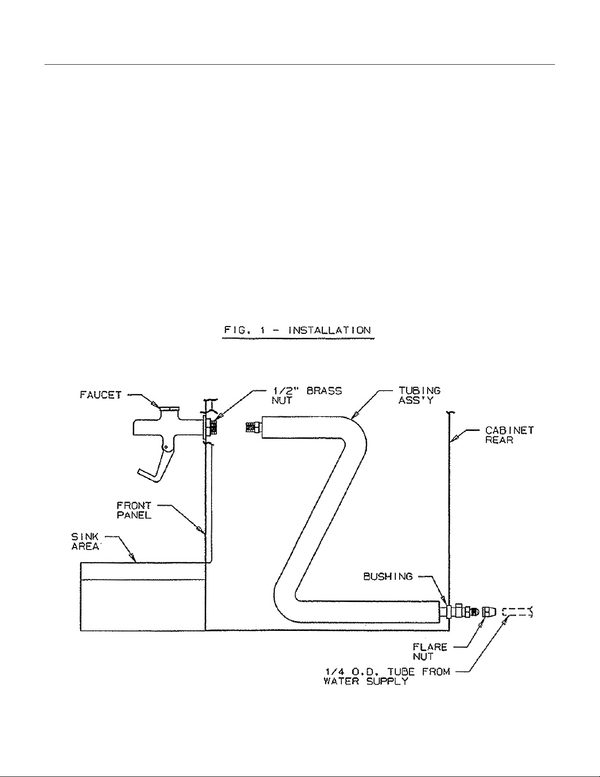
WA TER GLASS FILLER KIT
Installation Instructions
WARNING: Disconnect power to unit before
proceeding with installation
1. Prepare unit as follows:
· Remove lower front panel.
· Locate new holes in front panel.
2. Install faucet and tubing assembly as shown
below.
3. Connect field water supply to ¼ male flare fitting
on tubing assembly. Apply water pressure and
check all connections for leaks. Check faucet for
proper operation. Check that tubing assembly does
not interfere with wiring or electrical components.
4. Carefully reinstall panels on unit.
ID150, ID200, ID250
May 2002
Page 5

WA TER GLASS KIT - CON TINUED
ID150, ID200, ID250
May 2002
Page 6
ID150
A 4”
B 2.5”
ID200, ID250
A 6 1/8”
B 3 1/8”
Water inlet can be routed either from
the back or from underneath the
dispenser.
If from the back, remove the back and
bottom access panels.
If from below, only remove the bottom
access panel.
A hole is not needed at the
intersection of C and D, unless the
back access panel is retained.

for the installation of nugget ice diverting kit, KNUGDIV
The kit is used when dispensing nugget ice from an ID150, ID200 or ID250 ice
dispenser or equivalent Cornelius ice and beverage dispenser. It is designed to divert
the nugget ice into the dispenser’s chute. Follow these instructions to install the
diverting plate onto the dispenser.
Kit contents: diverting plate, RTV sealant.
1. Remove or melt all ice from the dispenser. Check agitator, replace it if it is bent or
deformed.
2. Disconnect dispenser from electrical power.
Diverting
Plate
Restrictor
Plate
Gasket
Chute
Chute
Mounting
Beverage Valves
ID150, ID200, ID250
ICE DI VERTER KIT
J
une 2016
Page 7

3. Remove merchandiser or stainless cover from upper front of dispenser.
4. Remove four hex nuts holding chute to dispenser, using a 3/8” nut driver or socket.
5. Remove chute from dispenser.
6. Apply a very thin bead or RTV to the back of the diverter mounting plate.
7. Place ice diverter plate onto the four mounting studs on the dispenser.
Note: Flange of diverting plate extends into storage hopper.
8. Position restrictor plate over diverting plate, adjust so
that at least 1 ½” inches of space is open below the
bottom edge. Full open will provide maximum ice flow,
any less than 1 ½” will restrict ice.
9. Reinstall gasket and ice chute. Do NOT overtighten
nuts.
10. Open front of electrical cover of dispenser, locate
circuit board. Adjust motor on time to a half second*,
adjust off time between agitation to every 3 hours.
11. Reconnect power, agitator should cycle a half second*. Check ice shutter
operation.
12. Return merchandiser or cover to unit.
* On beverage dispensers, set motor on time to 2 seconds.
11/2"
Set full
CCW*
Set full CW
Restrictor
Plate
Chute
Opening
ID150, ID200, ID250
ICE DI VERTER KIT
June 2016
Page 8

INI TIAL START UP
1. Sanitize the ice storage system as instructed on
page 11.
2. Fill hopper with sanitary ice.
3. Plug the unit’s power cord into an electrical
outlet and the lighted sign should come on.
Dispense several containers of ice.
In normal operation, pushing the ice dispenser
mechanism will cause ice to flow from the ice
chute. Ice flow will continue until the dispenser
mechanism is released.
CAUTION: Use caution to avoid spilling ice when
filling dispenser. Clean up immediately any spilled
ice from filling or operating the unit. To prevent
contamination of ice, the lid must be installed on
the unit at all times.
If the dispenser fails to dispense ice or beverage
see troubleshooting guide.
ID150, ID200, ID250
June 2016
Page 9

GATE RESTRICTOR PLATE
CAUTION: Disconnect power to dispenser before
installing, removing or adjusting restrictor.
ADJUSTMENT
This plate may be adjusted as shown to reduce or
increase the dispensing rate of ice, especially
desirable when using glasses or other containers
with small openings. Adjustment can be made by
sliding up or down with nuts loosened, to obtain
the desired amount of restriction.
ID150, ID200, ID250
May 2002
Page 10

CLEANING AND SAN I TIZING
The sink, grill and splash panel area should be
cleaned daily.
The following dispenser maintenance should
be performed at the intervals indicated:
DAILY (or as required)
Remove foreign material from vending area drip
tray to prevent drain blockage.
WEEKLY (or as required)
Clean vending area. Check for proper water
drainage from the vending area drip tray.
MONTHLY
Clean and sanitize the hopper interior (see
CLEANING INSTRUCTIONS).
CLEANING PRECAUTIONSS
WARNING: Disconnect Power Before Cleaning!
Do not use metal scrapers, sharp objects or
abrasives on the ice storage hopper, top cover and
the agitator disk, as damage may result.
Do not use solvents or other cleaning agents, as
they may attack the plastic material.
Soap solution - Use a mixture of mild detergent
and warm (100 degrees F) potable water.
ID150, ID200, ID250
May 2002
Page 11

CLEANING AND SAN I TIZING
MONTHLY & INITIAL START UP:
Sanitize the Ice Storage System.
Note: this should only be done by qualified
personnel.
CLEANING PRECAUTIONS
WARNING: Disconnect Power Before Cleaning!
Do not use metal scrapers, sharp objects or
abrasives on the ice storage hopper, top cover and
the agitator disk, as damage may result.
Do not use solvents or other cleaning agents, as
they may attack the plastic material.
Soap solution - Use a mixture of mild detergent
and warm (100 degrees F) potable water.
1. Unplug the electrical cord from the electrical
power.
2. Remove cover and discard all remaining ice.
3. Mix a solution of 1 ounce of household bleach to
2 gallons of potable water, or: mix a solution of any
locally approved sanitizer, following the directions
for mixing and applying that sanitizer.
CAUTION: When pouring liquid into the hopper, do
not exceed the rate of 1/2 gallon per minute.
Important: Perform the following at least once a
month.
4. Remove agitator assembly.
5. Using a long handle nylon bristle brush, clean
the interior of the hopper, and top cover with soap
solution. Clean the agitator assembly with soap
solution using a nylon brush or a sponge.
Thoroughly rinse the hopper, top cover and
agitator with clean potable water.
6. Remove merchandiser and ice chute cover from
dispenser.
7. With a nylon bristle brush or sponge, clean the
inside of the ice chute, gasket and cover with soap
solution and rinse thoroughly to remove all traces
of detergent.
8. Re-assemble Agitator assembly. Take special
care to ensure that the thumbscrew is tight.
9. Using a mechanical spray bottle filled with
sanitizing solution, spray the entire interior and
agitator assembly. Allow to air dry.
10. Re-assemble ice chute assembly.
11. Using a mechanical spray bottle filled with
sanitizing solution, spray the inside of the ice
chute. Allow to air dry.
12. Reinstall merchandiser.
13. Wipe the top edge of the ice hopper with the
sanitizing solution, allow to air dry.
14. Pour in fresh, sanitary ice and replace the
cover. Plug the unit in, and it is now ready to
dispense ice.
ID150, ID200, ID250
May 2002
Page 12

TROU BLE SHOOTING
IMPORTANT: Only qualified personnel should
service internal components or electrical wiring.
Should your unit fail to operate properly, check that
there is power to the unit and that the hopper
contains ice. If the unit does not dispense, check
the following chart under the appropriate
symptoms to aid in locating the defect.
Trouble Probable Cause
BLOWN FUSE OR CIRCUIT BREAKER.
A. Short circuit in wiring.
B. Defective gate solenoid.
C. Defective agitator motor.
GATE DOES NOT OPEN. AGITATOR DOES NOT TURN.
A. No power.
B. Bent depressor plate (does not actuate switch).
C. Defective dispensing switch.
GATE DOES NOT OPEN OR IS SLUGGISH. AGITATOR TURNS.
A. Defective gate solenoid.
B. Excessive pressure against gate slide.
C. Defective rectifier.
ICE DISPENSES CONTINUOUSLY.
A. Stuck or bent depressor plate (does not release switch).
B. Defective dispensing switch.
C. Improper switch installation.
SLUSHY ICE. WATER IN HOPPER.
A. Blocked drain.
B. Unit not level.
C. Poor ice quality due to water quality or icemaker problems.
D. Improper use of flaked ice.
ID150, ID200, ID250
May 2002
Page 13


Scoman
9
SCOTSMAN
R
v
: