Loading ...
Loading ...
Loading ...
8
Install Range Hood into
Hood Cabinet
The range hood attaches to the hood cabinet using four
mounting screws and washers.
NOTE: Hood cabinet must be capable of supporting 75 lb
(34 kg).
Prepare Range hood for mounting into cabinet
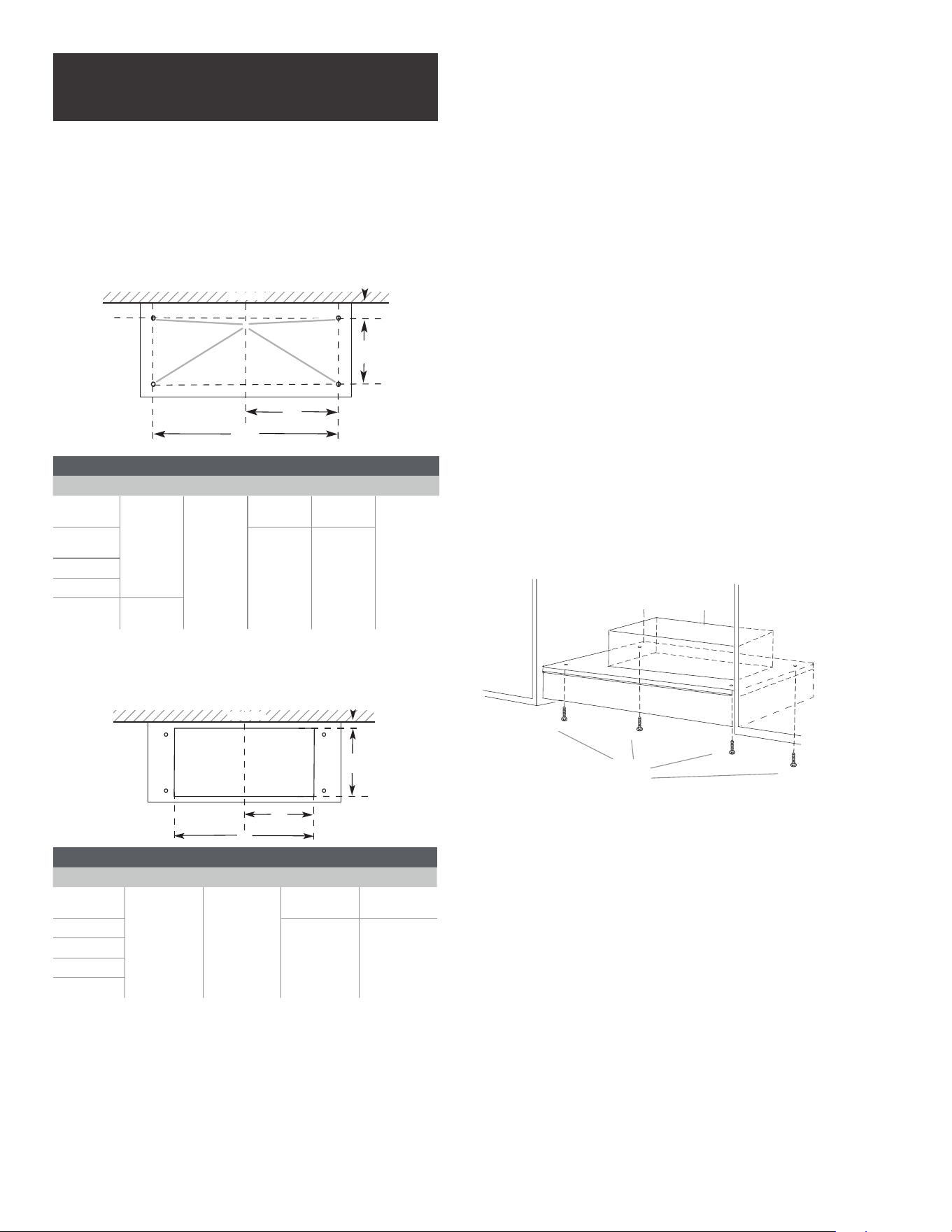
1. Mark the locations for the four mounting screws on the
hood cabinet as shown below.
2. Using a ⅛” (3 mm) drill bit, drill the 4 holes.
A
B
C
D
E
Wall
Centerline
MOUNTING HOLE DIMENSIONS
Model DIM A DIM B DIM C DIM D DIM E
EAR628S4
6″
(15.5 cm)
10
1
⁄16″
(25.6 cm)
12
5
⁄32″
(30.9 cm)
24
5
⁄16″
(61.8 cm)
Ø
1
⁄8″ (3mm)
EAR134S4
14
15
⁄16″
(38 cm)
29
13
⁄16″
(75.8 cm)
EAR140S4
EAR146S4
ETR134S1
2″
(5 cm)
3. Mark the cutout for the rectangular clearance hole for the
upper range hood motor housing as shown.
4. Using a jigsaw or keyhole saw, cut out the rectangular
clearance hole for the upper range hood housing.
Wall
Centerline
A
B
C
D
UPPERHOOD MOTOR HOUSING DIMENSIONS
Model DIM A DIM B DIM C DIM D
EAR628S4
4
1
⁄4″
(10.8 cm)
15
5
⁄16″
(38.9 cm)
7
5
⁄8″
(19.45 cm)
23
7
⁄16″
(59.5 cm)
EAR134S4
14
1
⁄2”
(36.8 cm)
28
15
⁄16″
(73.5 cm)
EAR140S4
EAR146S4
ETR134S1
Install the range hood into the hood cabinet
1. Determine and make all necessary cuts in the wall or
roof for the vent system. Install the vent system before
installing the cabinet hood insert. See the “Venting
Requirements” section.
2. Determine the location where the power supply cable will
be run through the wall.
3. Drill a 1¼” (3.2 cm) hole at this location.
4. Pull enough power supply cable through the wall to allow
for easy connection to the terminal box.
5. Remove terminal box cover and set aside.
6. Install the 10” (25.4 cm) square x 10” (25.4 cm) round
vent transition with damper to top side of the
range hood, using 4 - 3.5 x 9.5 mm screws.
7. Remove knockout from the top of the vent hood and
install a UL listed or CSA approved ½” (1.3 cm) strain
relief.
8. Place the hood insert near its mounting position
and run the power supply cable through the strain relief
into terminal box (enough to make connection).
9. Tighten the strain relief screws.
10. Using 2 or more people, lift the hood insert into
hood cabinet.
11. Fasten the hood insert using four 5 x 45 mm screws to the
hood cabinet and tighten securely.
I WARNING
EXCESSIVE WEIGHT HAZARD
USE TWO OR MORE PEOPLE TO MOVE AND INSTALL HOOD
INSERT.
FAILURE TO DO SO CAN RESULT IN BACK OR OTHER IN-
JURY.
Upper Hood
Insert Motor Housing
4 mounting
screws
Loading ...
Loading ...
Loading ...