
ENGLISH
P/NO : MFL69329502
www.lg.com
After reading this user manual, keep it in an easily accessible place.
HVAC Controller(ACP IV)
HVAC Touch(AC Smart IV)
BACnet Touch(AC Smart BACnet)
BACnet(ACP BACnet)
Lonworks (ACP Lonworks)
OWNER’S MANUAL(GUI)
AIR
CONDITIONER


i
ENGLISH
i
EXPLANATORY NOTES
EXPLANATORY NOTES
Copyrights
The contents of this ACS IV Controller User Manual are protected by international copyright laws,
and the Computer Program Protection Act. The contents of the User Manual and the programs
mentioned herein may only be used under license from LG Electronics in strict adherence to the user
agreement.
You may not reproduce or distribute, by any means, copies of this User Manual, or any part of it,
without prior approval from LG Electronics.
Copyright © 2014 LG Electronics. All rights reserved.
Registered Trademarks
ACS IV Controller is a registered trademark of LG Electronics. All other products and company
names are trademarks of their respective owners and are used for illustrative purposes only.

ii
ENGLISH
ii
EXPLANATORY NOTES
Product Features
Built-in Web Server
You can use Internet Explorer to access various online content without additional software.
Latest software version of Adobe Flash should be installed on your computer.
Simple Central Controller Interface
You can interface ACS IV Controller with a 16-room simple central controller.
AC Manager IV Interface
You can connect ACS IV Controllers with a PC based AC Manager IV to use the various AC Manager
IV functions. You can also use the scheduling function, even if the PC with AC Manager IV is turned
off.

iii
ENGLISH
iii
EXPLANATORY NOTES
How to Use This Guide
It is highly suggested that this User Manual be read in its entirety before using the ACS IV Controller.
Store this guide so that is also easily accessible.
Notations Used In This Guide
• Control buttons displayed within the system are marked by boldface text in square brackets ([ ]).
Example: [OK], [Save]
• Option titles displayed in the program are marked by boldface text.
Example: Start, Programs
• Keyboard strokes used by the system are marked by boldface text in angle brackets (< >).
Example: <Esc>
NOTES
y
This manual Covers the ACP IV, AC Smart IV, AC Smart BACnet, ACP BACnet version 4.0.0
or later, ACP Lonworks version 2.2.0 or later.
y
The contents of this manual may differ from the actual function according to the latest SW
version.
NOTES
y
You will need the Adobe Flash Player be installed for the Web control.
(Recommended specification : Adobe Flash Player 11)
y
The special characters (^), (‘) and (,) are not available for user or object names within device.

iv
ENGLISH
iv
EXPLANATORY NOTES
Comparison of Models
There are some differences depending on the model.
O : Supported
X : Not supported
Related
Menu
Function ACP IV
ACP
BACnet
AC
Smart
IV
AC
Smart
BACnet
ACP
Lonworks
Control/
Monitor,
Installing
Exp.I/O Installing, Control/
Monitor
O O* O O* O**
Control/
Monitor,
Installing
Chiller Installing, Control/
Monitor
Optional
X
Optional
X X
Interlocking,
Energy
Report,
Event Log,
Environment
Email
(Setting, Interlocking/Error
Notification, Energy Report/
Event Log send)
O O O O O
Energy
Report,
Event Log
PC Save
(Energy Report/Event Log
save)
O O O O O
Environment
LGAP Setting
(Master/Slave)
X X O X X
Environment
Update S/W, DB
management
Controller,
Web
Controller
Controller,
Web
Controller,
Web
Controller,
Web
Environment Screen Setting X X O O X
Environment
Network
Setting
IP Information,
DNS Server
Controller
Controller,
Web
Controller,
Web
Controller,
Web
Controller
HTTP Port
Setting
X Web
Controller,
Web
Controller,
Web
X
Environment
BACnet
Setting
Unit, Device
ID, Vnet
Number
X
Controller,
Web
X
Controller,
Web
X
BACnet Port
Setting
X Web X
Controller,
Web
X
* ACP BACnet, AC Smart BACnet don’t support Exp. I/O’s BACnet points
**ACP Lonworks doesn’t support Exp. I/O’s Lonworks points

v
ENGLISH
v
TABLE OF CONTENTS
1
SAFETY
PRECAUTIONS
7
STARTING
7 Login and logout
8 – Login
8 – Logout
9 Home screen composition and
features
10 Emergency situation occurrence
and reset
10 – Emergency situation occurrence
11 – Emergency situation reset
13
USING THE PROGRAM
13 Control/Monitor
13 – Control/Monitoring screen
composition and features
19 – Device Control
57 – Monitoring a Device
58 Schedule
58 – Schedule Screen composition and
features
59 – Creating Schedules
62 – Checking Schedules
63 – Editing Schedules
64 – Deleting Schedules
65 Auto Logic
65 – Peak Control
74 – Demand Control
77 – Time-limit Operation
83 – InterLocking
90 Energy Report
90 – Statistics Screen Composition and
Features
92 – Querying Energy Report
94 Event Log
94 – Event log screen composition and
features
96 – Querying Event
97 Installing
97 – Device setting screen composition
and function
98 – Registering Device
116 – Managing Device
120 – Cycle Monitoring
122 Environment
123 – General Setting
134 – Screen Setting (AC Smart IV, AC
Smart BACnet Only)
139 – Advance Setting
148 – Customer Setting
154 – Network Setting (ACP BACnet, AC
Smart IV, AC Smart BACnet Only)
159 – E-Mail Setting
164 – TMS Setting
170 – Channel Setting
172 – BACnet Setting
TABLE OF CONTENTS

vi
ENGLISH
MEMO
1
ENGLISH
SAFETY PRECAUTIONS
SAFETY PRECAUTIONS
• This product must be installed by an installation professional from an LG authorized service
center.
• Warranty will be voided if installed by non-certified or unauthorized persons.
• Follow the safety precautions to prevent any unforeseen dangers or damage.
• This product has been designed for business use, or for areas outside the home, and has
passed the Electromagnetic Interference Test.
WARNING
This symbol indicates a potentially hazardous situation which, if not avoided, could result in
death or serious injury.
CAUTION
This symbol indicates a potentially hazardous situation which, if not avoided, may result in
minor or moderate injury.
WARNING
Installation
y To reinstall the product, please contact the your dealer or a service center for
reinstallation service.
- Installation of the product by an unauthorized person may result in fire, electric shock, explo-
sion, injury, or a malfunctioning of the product.
y Do not twist or damage the power cord.
- It may cause fire or electric shock.
y For electrical work, please contact the dealer from where you purchased the product, or
a service center.
- Disassembly or repair by an unauthorized person may result in fire or electric shock.
y For installation of the product, please contact the dealer from where you purchased the
product, or a service center.
- Installation of the product by an unauthorized person may result in fire, electric shock, explo-
sion, injury, or a malfunctioning of the product.
y For electrical work, have an electrician follow the installation manual and specified
circuit diagram.
- Using an unsuitable cord, or having a non-professional work on the electricals may result in fire
or electrical shock.

2
ENGLISH
SAFETY PRECAUTIONS
y Do not place the product near a fire source.
- It may result in the product catching fire.
y If the product is installed in a hospital or a communication base station, provide
sufficient protective equipment against electrical noise or interference.
- The product may malfunction or other products may work abnormally.
y Securely install the product.
- If the product is not secured during installation, it may fall or malfunction.
y Read the manual thoroughly to correctly install the product.
- If not, an incorrect installation may cause fire or electric shock.
y When wiring the product, do not use a non-standard cable, nor extend the cable
excessively.
- It may cause fire or electric shock.
y Securely install the power cord and communication cable.
- An unsecure installation may result in fire or electric shock.
y Do not connect the power cord to the communication terminal.
- It may cause fire, electric shock, or a product malfunction.
y Do not install the product in an area near combustible gas.
- It may result in fire, electric shock, explosion, injury, or a malfunctioning of the product.
Operation
y Do not place a heavy object on the power cord.
- It may cause fire or electric shock.
y Do not change or extend the power cord arbitrarily.
- It may cause fire or electric shock.
y Use the cord specific to the product.
- Using an unauthorized non-standard cord may result in fire or electric shock.
y Do not use a heat device near the power cord.
- It may cause fire or electric shock.
y Ensure that water never gets into the product.
- It can result in an electric shock, or product malfunction.
y Do not place any container with liquid on the product.
- The product may malfunction.
y Do not click(touch) the product with wet hands.
- It may cause fire or electric shock.

3
ENGLISH
SAFETY PRECAUTIONS
y Use standard components.
- Use of an unauthorized product may result in fire, electric shock, explosion, injury, or a malfunc-
tioning of the product.
y If the product has been submerged in water, contact a service center.
- It may cause fire or electric shock.
y Do not cause shock to the product.
- The product may malfunction.
y Do not store or use any combustible gas or flammable substances near the product.
- It may cause fire, or a product malfunction.
y Do not disassemble, repair, or revamp the product arbitrarily.
- It may cause fire or electric shock.
y Children and the elderly should use the product under adult supervision.
- Carelessness may cause an accident, or the product may malfunction.
y Children should not operate the product without adult supervision.
- The product may be damaged or it may fall, causing injury to children.
y Product must operate between operating temperatures as outlined in this manual.
- If the product is used outside this range, the product may be severely damaged.
y Do not press the switch or button with a sharp object.
- It can result in an electric shock, or the product may malfunction.
y Do not handle wiring of this product while it is turned on.
- It may cause fire or electric shock.
y If unusual sounds or odor are coming from the unit, immediately power off.
- It may cause fire or electric shock.
y Do not place a heavy object on the product.
- The product may malfunction.
y Do not spray water on the product, or clean it with a water-soaked cloth.
- It may cause fire or electric shock.
y Do not use the product for the preservation of animals and plants, precision
instruments, art pieces, or for other special purposes.
- It may cause property damage.
y Dispose the packing material safely.
- The packing material may result in personal injury.

4
ENGLISH
SAFETY PRECAUTIONS
CAUTION
Installation
y Securely install the product in an area where the weight of the product can be supported.
- The product may fall and be destroyed.
y Install the product in an area shielded from rain.
- If water gets into the product, it may malfunction.
y Do not install the product in a humid area.
- If the product is damp, it may malfunction.
y Do not use the product where there is oil, steam, or sulfuric gas.
- It may effect the product's performance, or damage it.
y Check the rated power capacity.
- It may cause fire, or a product malfunction.
y Use the adapter provided with the product or power from a class 2 24 V~ transformer,
depending on model.
- If a non-standard adapter is used, the product may malfunction. The adaptor is not provided
with the AC Smart package sold in the U.S.
y Be careful not to drop or damage the product when moving it.
- The product may malfunction or the person may sustain an injury.
y Ensure that the cord is connected securely to prevent dew, water, or insects from getting
into the product.
- If a foreign substance gets inside, it may cause an electric shock or the product may malfunc-
tion.
Operation
y Clean the product with a soft cloth, but not with a solvent-based detergent.
- The use of a solvent-based detergent may cause fire or deform the product.
y Do not let the product come into contact with a metal substance.
- The product may malfunction.
y When sterilizing or disinfecting, power off the product.
- The product may work abnormally.
y Do not click(touch) inside the product while powered on.
- The product may malfunction.
5
ENGLISH
SAFETY PRECAUTIONS
y Periodically, check the product and do maintenance, especially if it has been running for
extended periods of time.
- If the product is allowed to run for extended periods of time, the product may deteriorate causing
injury to the user.
y Do not leave the product near a flower base, water bottle, or any other liquids.
- It may cause fire or electric shock.
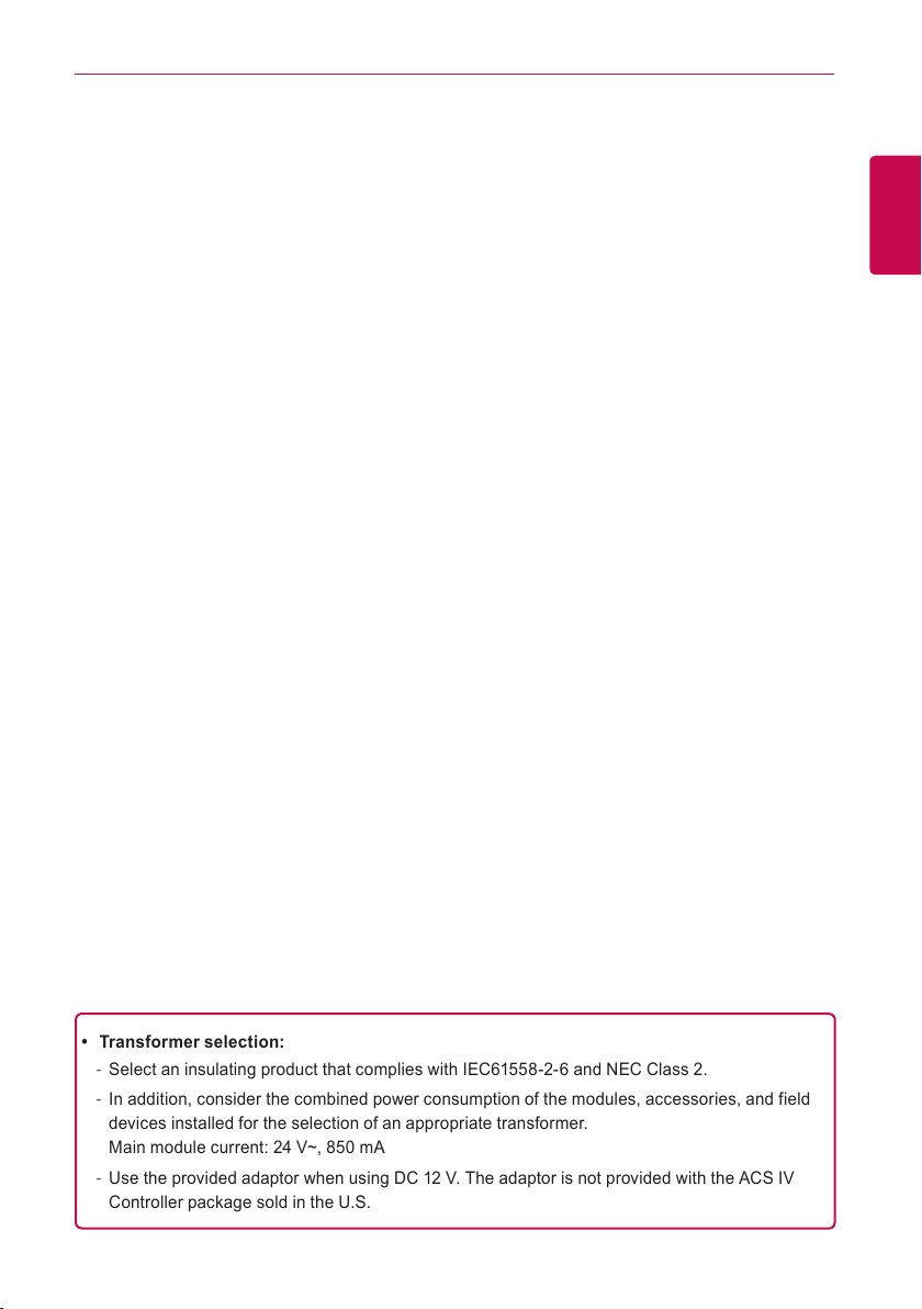
y Transformer selection:
- Select an insulating product that complies with IEC61558-2-6 and NEC Class 2.
- In addition, consider the combined power consumption of the modules, accessories, and field
devices installed for the selection of an appropriate transformer.
Main module current: 24 V~, 850 mA
- Use the provided adaptor when using DC 12 V. The adaptor is not provided with the ACS IV
Controller package sold in the U.S.
6
ENGLISH
SAFETY PRECAUTIONS
Class A device
NOTES
This equipment has been tested and found to comply with the limits for a Class A digital device,
pursuant to part 15 of the FCC Rules.
These limits are designed to provide reasonable protection against harmful interference when
the equipment is operated in a commercial environment.
This equipment generates, uses, and can radiate radio frequency energy and, if not installed
and used in accordance with the instruction manual, may cause harmful interference to radio
communications. Operation of this equipment in a residential area is likely to cause harmful
interference in which case the user will be required to correct the interference at his own
expense.
Caution
Changes or modifications not expressly approved by the manufacturer responsible for
compliance could void the user’s authority to operate the equipment.
Disposal of your old appliance
1. When this crossed-out wheeled bin symbol is attached to a product it
means the product is covered by the European Directive 2002/96/EC.
2. All electrical and electronic products should be disposed of separately
from the municipal waste stream via designated collection facilities
appointed by the government or the local authorities.
3. The correct disposal of your old appliance will help prevent potential
negative consequences for the environment and human health.
4. For more detailed information about disposal of your old appliance,
please contact your city o!ce, waste disposal service or the shop
where you purchased the product.

7
ENGLISH
STARTING
STARTING
This section explains how to connect to the system and register devices to setup the environment
(prior to using ACS IV Controller).
Login and logout
The following explains how to log in and out of ACS IV Controller.
ACS IV Controller can be controlled by entering the IP address of the ACS IV Controller in the
address bar of Internet Explorer without the installation of another program. The ACS IV Controller
Web server is executed automatically.
8
ENGLISH
STARTING
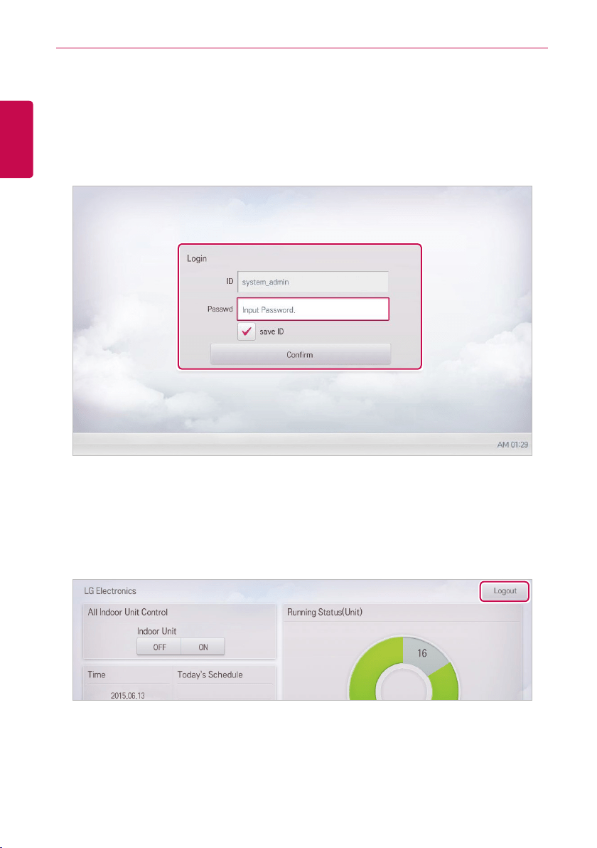
Login
You can login as follows:
1. Run ACS IV Controller.
2. After entering your ID and password in the login window, click(touch) the [Confirm] button.
• You should be logged in now.
Logout
You can logout as follows:
1. On the top right of the ACS IV Controller home screen, click(touch) the [Logout] button.
• You should be logged out now.
9
ENGLISH
STARTING
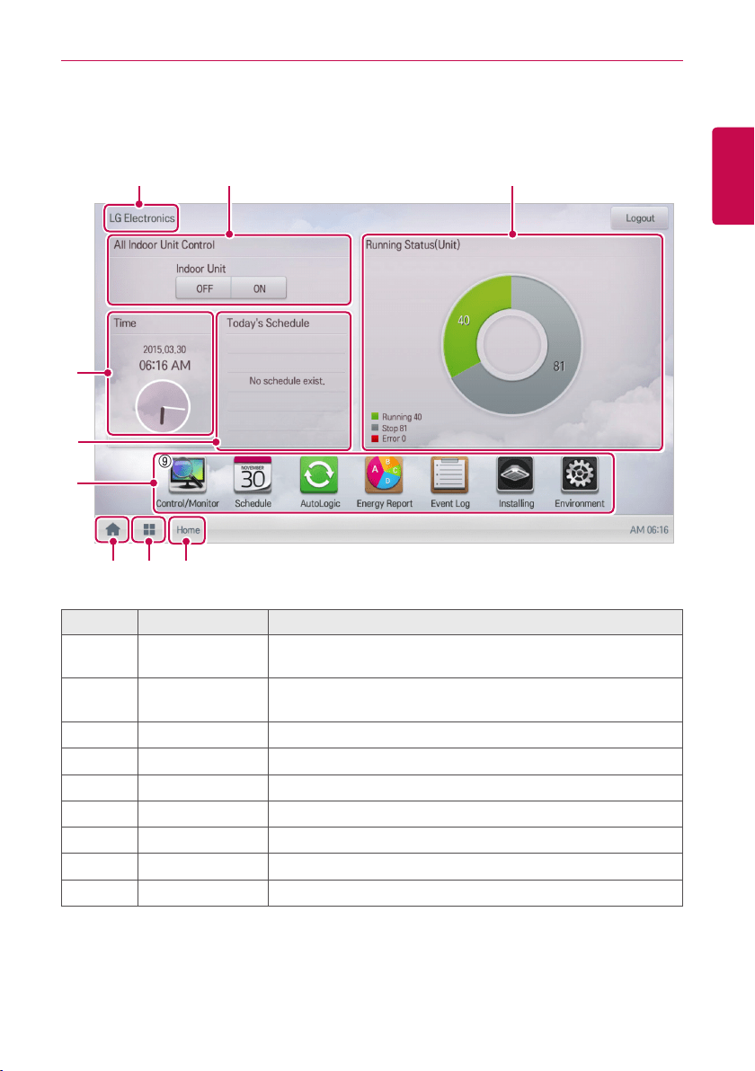
Home screen composition and features
The following explains the home screen composition and features.
⑨
① ②
③
⑤
④
⑥ ⑦ ⑧
Number Item Description
①
All Indoor Unit
Control
ON / OFF control of all indoor units.
②
Running Status
(Unit)
Checks if the devices are operating, stopped, or in error.
③
Time Check the current date and time.
④
Today's Schedule Check the registered schedules in chronological order.
⑤
Main Menu Use ACS IV Controller main menu.
⑥
Home Return to the home screen.
⑦
View Menu Display the active menu.
⑧
Current Menu Display the name of the active menu.
⑨
Site name Display registered site name.
⑨
10
ENGLISH
STARTING
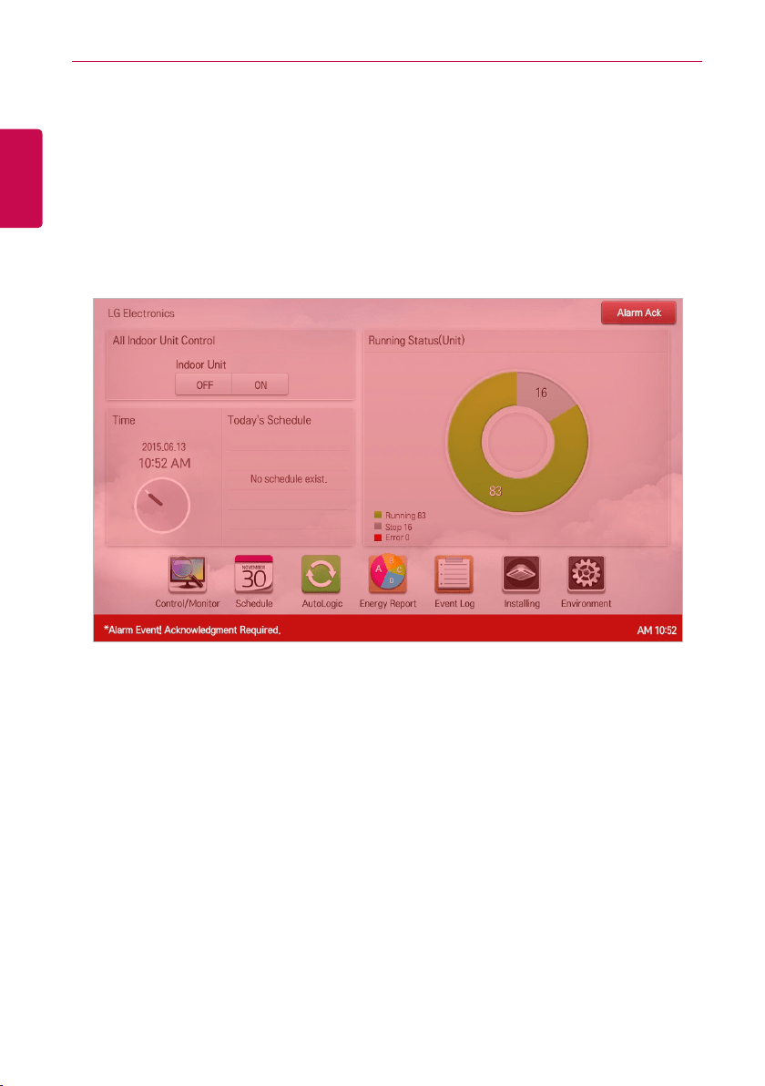
Emergency situation occurrence and reset
When an Alarm ACK Required program occurs, the entire home screen turns red to indicate
Acknowledgement is required. The alarm condition must be cleared before any other control can be
performed. For details on how to set emergency program, refer to Managing Program.
Emergency situation occurrence
When an emergency situation occurs, the alert screen is displayed on home screen as follows.
11
ENGLISH
STARTING
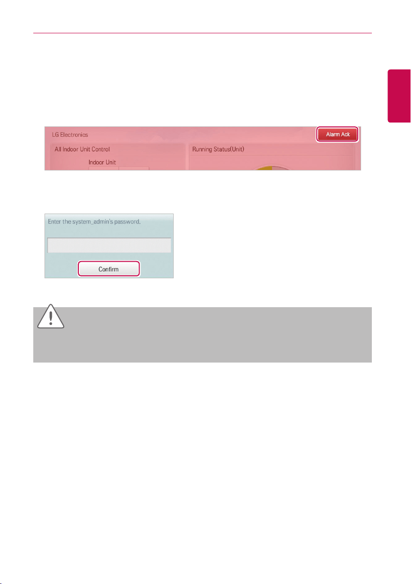
Emergency situation reset
Emergency alert screen is maintained until the emergency situation is reset. You can reset
emergency situation as follows.
1. Touch [Alarm Ack] button at the top right side of the emergency situation screen.
• Manager password input screen is displayed.
2. Input manager password and touch [Confirm] button.
• If the password is correct, the emergency situation is reset.
Caution
Emergency situation notice will be generated again until the cause of emergency situation is
removed.
You may have to check Interlocking to determine what the alarm cause is.

12
ENGLISH
MEMO
13
ENGLISH
USING THE PROGRAM
USING THE PROGRAM
The following explains how to use the ACS IV Controller functions.
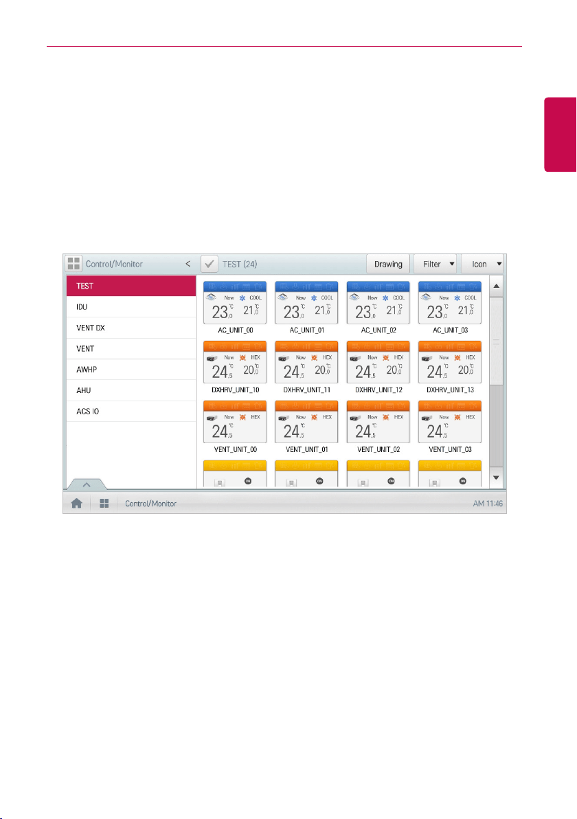
Control/Monitor
Control/Monitoring is the menu to combine several devices that can be commonly monitored into one
unit for easy management. The following explains the Control/Monitor menu options.
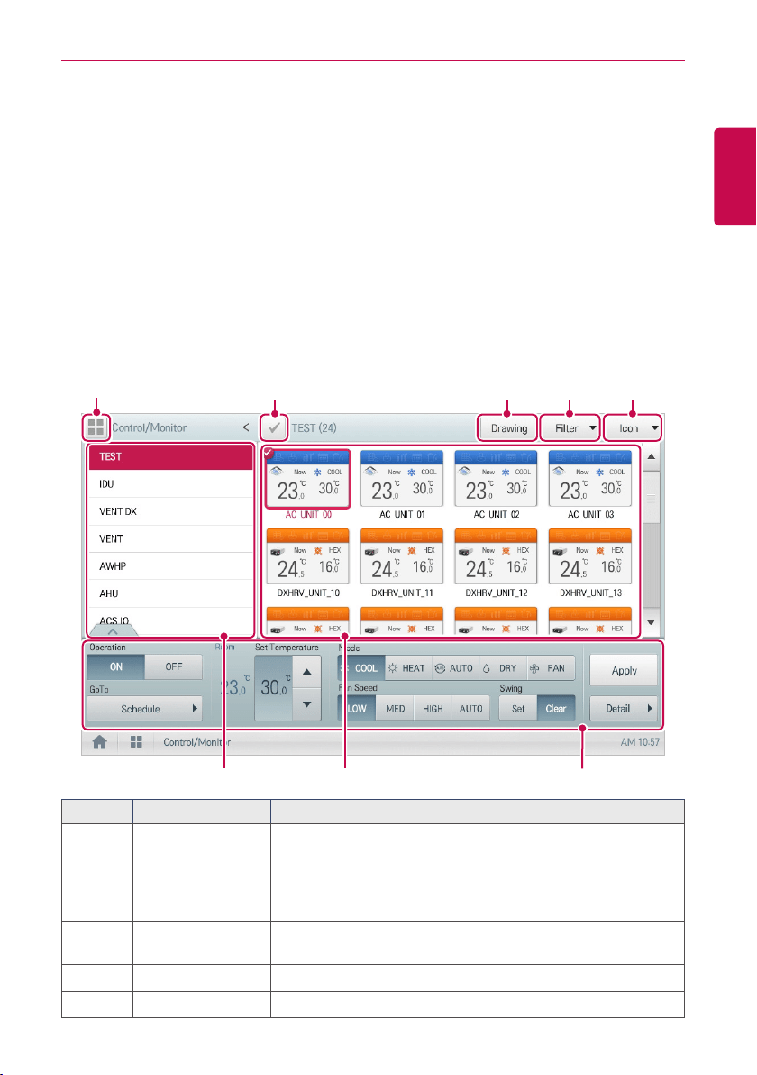
Control/Monitoring screen composition and features
The following explains Control/Monitoring screen composition and features.
① ② ③ ④
⑤ ⑥ ⑦
Number Item Description
①
Select/Deselect All Select/deselect all devices in a group (select = red check).
②
[Drawing] Button View floor plans of a group.
③
[Filter] Button
Select which device types are displayed for monitoring and
control.
④
View Type Select
Select a view type(Icon/Simple) for the monitoring screen.
(Refer following View Type)
⑤
Group List Check device group listings.
⑥
Monitoring Screen Check the control status of a device.
⑧
14
ENGLISH
USING THE PROGRAM
Number Item Description
⑦
Device Control Box
y Display the device control menu.
y The device control box shows different menus depending on
the device. (For more on Control Menu per Device)
⑧
[Multiple Group
Selection] Button
y Control the device by selecting multiple groups.
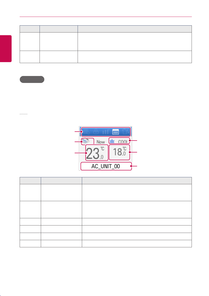
View Type
Control/Monitor menu has two different types of view(Icon, Simple). The following shows the screen
composition and features per view type.
Icon
The control status is shown in icons. The device icon has a composition and feature as follows.
⑥
⑤
④
①
②
③
Number Item Description
①
Operation Mode and
Device Status Icon
The color at the top of the icon box shows the current
operation mode, and the status of the device is indicated as
an icon.
②
Device Icon
The device to be controlled is indicated as an icon.
(The device shown may not represent the appearance of the
actual unit.)
③
Current Temperature Display the current temperature.
④
Operation Mode Display the operation mode of the device.
⑤
Desired Temperature Display the desired temperature.
⑥
Device Name Display the name of the device.
15
ENGLISH
USING THE PROGRAM
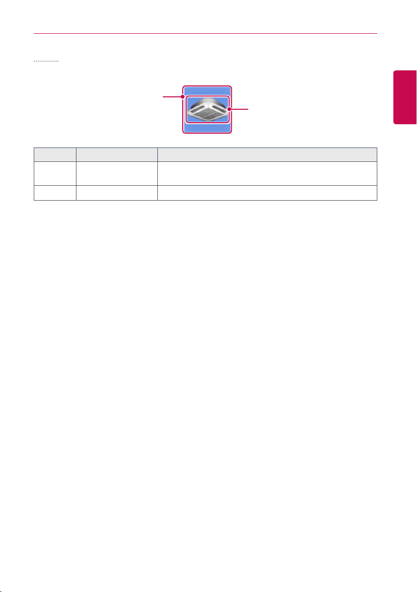
Simple
The control device and operation mode are displayed only.
①
②
Number Item Description
①
Operation Mode
The color of the box indicates the current operation mode.
Refer to following section.
②
Device Icon The device to be controlled is indicated as an icon.
16
ENGLISH
USING THE PROGRAM
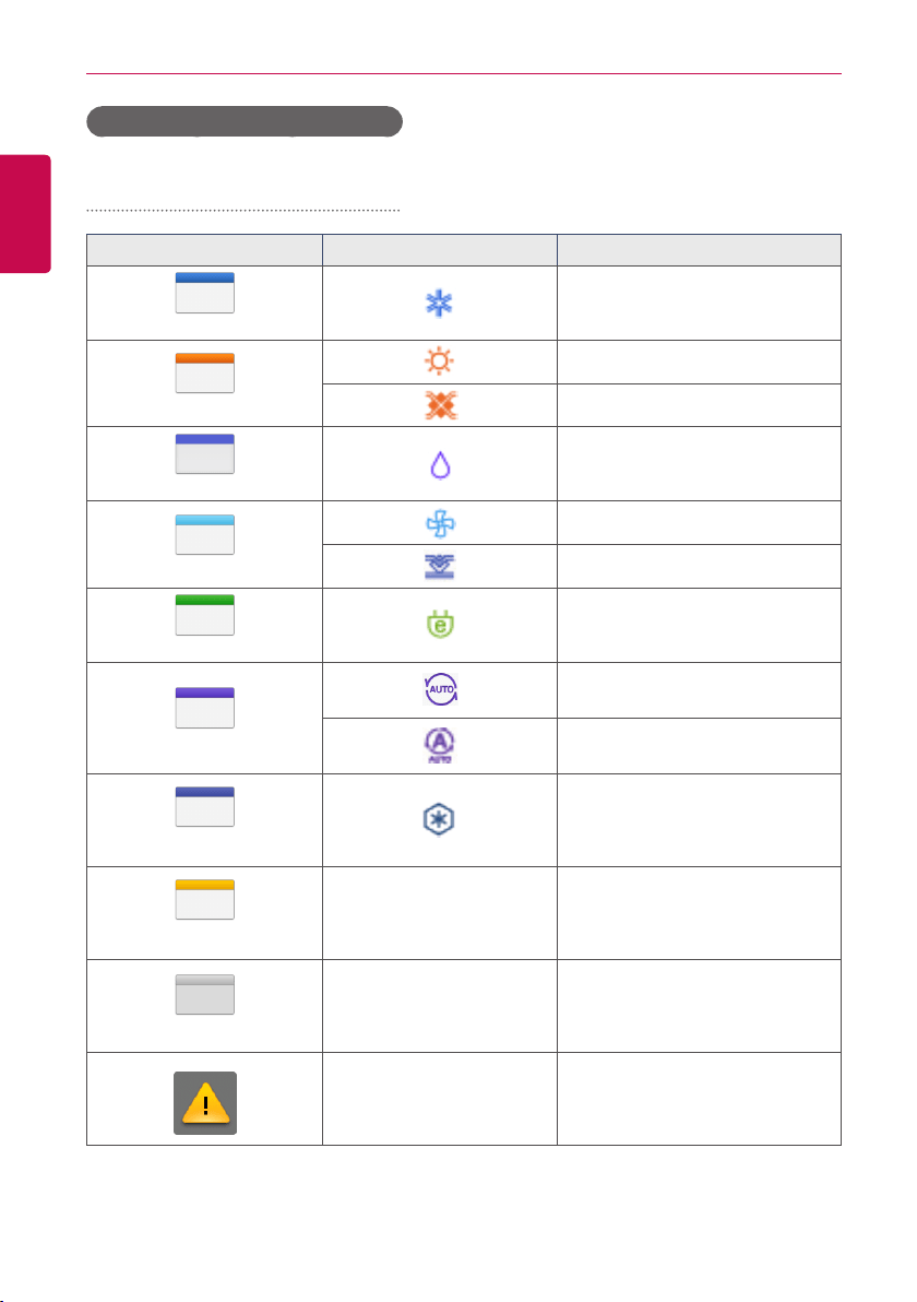
Monitoring screen colors and icons
Box colors and operation mode per icon
Color Icon Operation Mode
(Blue)
Cooling
(Orange)
Heating
Ventilation, Electric Heat
(Navy)
Dehumidification
(Sky Blue)
Fan
Ventilation, General
(Green)
Power Saving
(Purple)
Auto
Ventilation, Auto
(Sapphire Blue)
Chiller, Ice
(Yellow)
- ON or Short
(Gray)
- OFF or Open
- Error
17
ENGLISH
USING THE PROGRAM
Device status icon
Icon Device Status
Filter Exchange
Full Lock On
Peak/Demand Control
Schedule
GHP Oil Alarm
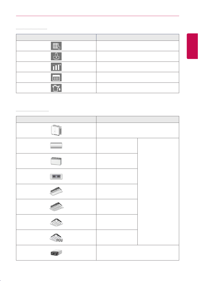
Control device icon
Icon Device Type
Outdoor Device
Wall Mounted
Indoor Device
Floor Mounted
Duct
Cassette(1Way)
Cassette(2Way)
Cassette(4Way)
FCU
ERV, ERV DX
18
ENGLISH
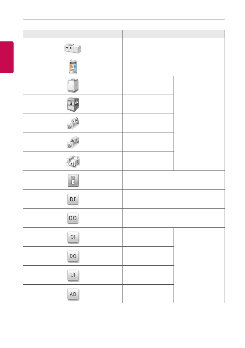
USING THE PROGRAM
Icon Device Type
AHU
AWHP or Hydrokit
Water-cooled scroll
chiller
Chiller
Air-cooled scroll chiller
Turbo chiller
Screw chiller
ABS chiller
DOKIT
DI
DO
DI
Exp. I/O
DO
UI
AO

19
ENGLISH
USING THE PROGRAM
Device Control
You can control the devices as follows.
1. From the main menu, click(touch) the [Control/Monitor] menu icon.
2. Click(Touch) the device group you want to control from the group list.
• The monitoring screen for the device is displayed.
3. Click(Touch) the device you want to control.
• To select all devices, click(touch) the button at the top.
• The device control area appears at the bottom of the screen.
4. In the device control box, set the control status of the device.
• The device control box shows a different menu depending on the device. For information
about the control area for each device, refer to Control Menu per Device.
5. Once you have finalized the settings, click(touch) the [Apply] button.
20
ENGLISH
USING THE PROGRAM
Control Menu per Device
The control box menu differs depending on the device. The following shows the control box menu
per device.
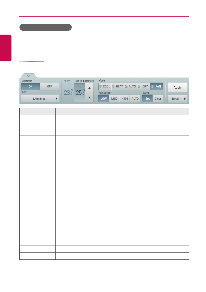
Indoor Device
The following is the indoor unit control menu and features.
Item Description
Operation
y [ON] Button: Starts the operation of the device similar to occupied.
y [OFF] Button: Stops the operation of the device similar to unoccupied.
GoTo
[Schedule▶] Button: Move to Schedule menu.
Room Display the current temperature at configured sensor(s).
Set Temperature
Click(Touch) [▲]/[▼] to set the temperature.
(The maximum/minimum temperatures that can be set may differ depending
on the model of unit controlled.)
Mode
y [COOL] Button: Cooling Mode Request.
y [HEAT] Button: Heating Mode Request.
y [AUTO] Button: Evaluates the operating environment conditions and
automatically sets the mode of operation.
y [DRY] Button: You cannot set the temperature in this mode.
y [FAN] Button: Fan runs without temperature control to clean the air. You
cannot set the temperature in this mode.
Fan Speed
y [LOW] Button: Slow fan speed.
y [MED] Button: Medium fan speed.
y [HIGH] Button: Fast fan speed.
y [AUTO] Button: Fan speed automatically adjusts between low, medium
and high fan speeds.
Swing
y [Set] Button: Turns on automatic oscillation of the louvers if present.
y [Clear] Button: Turns off automatic oscillation of the louvers if present.
[Apply] Button Apply control menu setting to the device
[Detail. ▶] Button
Controls details.
21
ENGLISH
USING THE PROGRAM
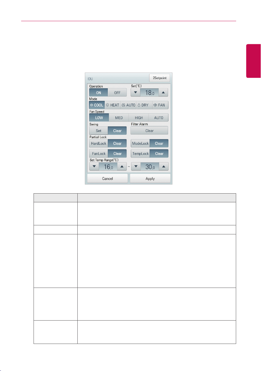
• Indoor unit fine control
In the control menu of the indoor unit, touch [Detail. ▶] button, and in the displayed detail
control window, you can control detail items. The composition and functions of the detail menu
are as follows.
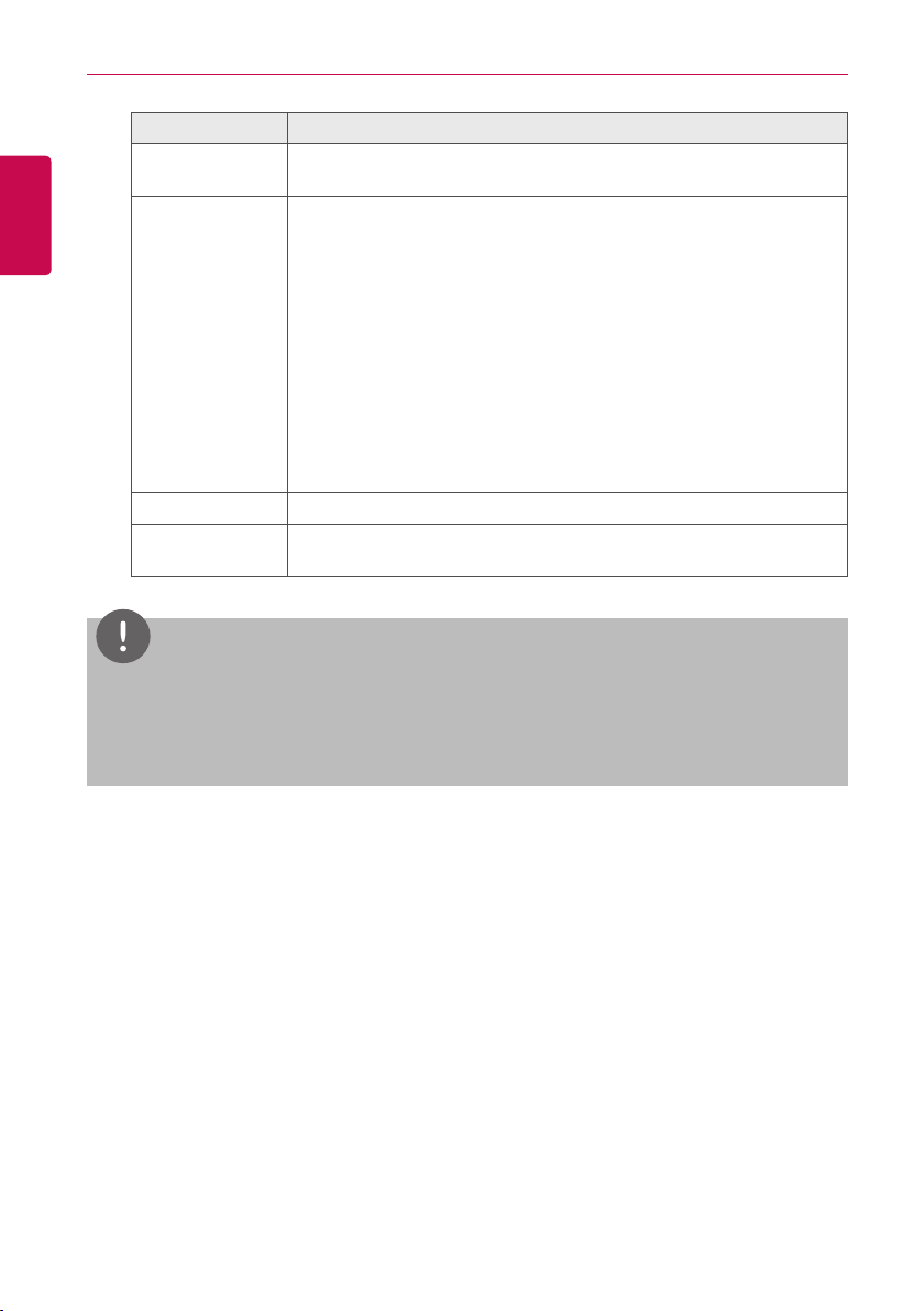
Item Description
Operation
y [ON] Button: Starts the operation of the device similar to occupied.
y [OFF] Button: Stops the operation of the device similar to
unoccupied.
Set Click(Touch) [▲]/[▼] to set the temperature.
Mode
y [COOL] Button: Cooling Mode Request.
y [HEAT] Button: Heating Mode Request.
y [AUTO] Button: Evaluates the operating environment conditions and
automatically sets the mode of operation.
y [DRY] Button: You cannot set the temperature in this mode.
y [FAN] Button: Fan runs without temperature control to clean the air.
You cannot set the temperature in this mode.
Fan Speed
y [LOW] Button: Slow fan speed.
y [MED] Button: Medium fan speed.
y [HIGH] Button: Fast fan speed.
y [AUTO] Button: Loops from low to medium to high fan speeds.
Swing
y [Set] Button: Turns on automatic oscillation of the louvers if present.
y [Clear] Button: Turns off automatic oscillation of the louvers if
present.
22
ENGLISH
USING THE PROGRAM
Item Description
Filter Alarm
Click(Touch) the Disable button to deactivate the filter exchange alarm.
(Model dependant.)
Partial Lock
y [HardLock] Button: Disables thermostat control for all features.
y [Clear] Button: All functions are unlocked.
y [ModeLock] Button: Disables thermostat control for local mode
setting.
y [Clear] Button: Mode is unlocked.
y [FanLock] Button: Disables thermostat control for local fan speed
setting.
y [Clear] Button: Fan speed is unlocked.
y [TempLock] Button: Disables thermostat control for local
temperature setting.
y [Clear] Button: Temperature setting is unlocked.
Set Temp Range Click(Touch) [▲]/[▼] to set the temperature limit.
[2Setpoint] or
[IDU 2Set] Button
Set functions in 2Setpoint or IDU 2set(US only Option)
NOTES
y
Depending on the installation site specifications, either the Auto Mode or 2Set Auto Mode
can be selected. Go to
Environment > Advance Setting > Auto Mode Option
and select a
desired auto mode type.
y
2Set Auto Mode option is only available in the U.S.
23
ENGLISH
USING THE PROGRAM
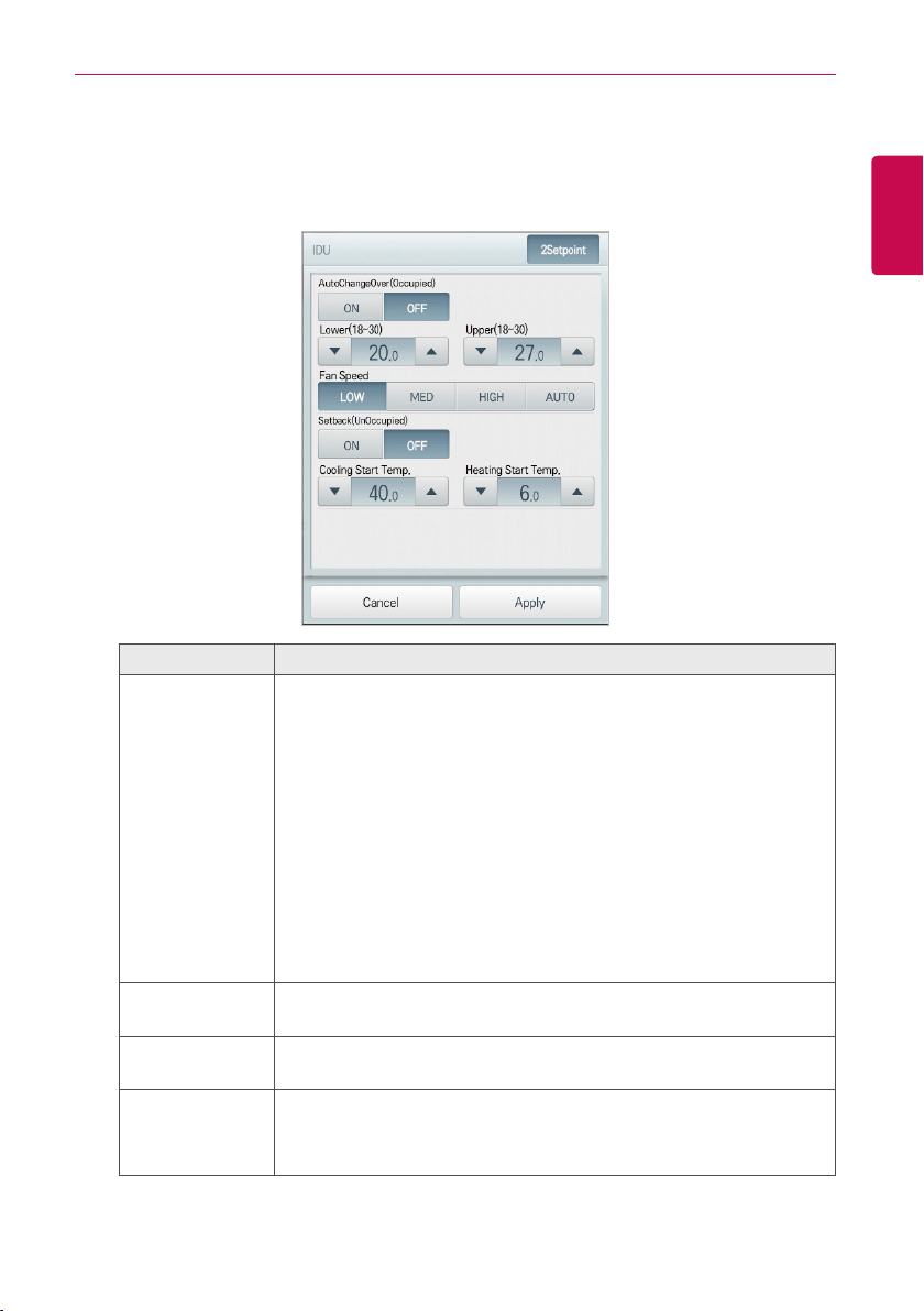
• Indoor 2Setpoint (Auto Mode)
In the detail control window of the indoor unit, touch [2Setpoint] button, and in the displayed
automatic control setting window, you can set the automatic control. The composition and
functions of the automatic control menu are as follows.
Item Description
Auto Change
Over
Set the auto change over function to switch the operation mode
automatically to keep the proper room temperature.
When Room Temp. > Upper, request Cool operation mode. When
Room Temp. < Lower, requests Heat operation mode. When Room
Temp.≤(Upper-Temperaturedifference)orRoomTemp.≥(Lower+
Temperature differece), requests Fan operation mode.
(You can set up Temperature differernce in Environment > Advance
Setting > Temperature limit setting.) (The auto change over function
works well with "Heat Recovery" model. For other models, functionality
is limited.)
y [ON] Button: Enable Auto Change Over
y [OFF] Button: Disable Auto Change Over
Lower
Click(Touch) [▲]/[▼] to set the lower limit temperature range.
(18°C~30°C / 64°F~86°F).
Upper
Click(Touch) [▲]/[▼] to set the upper limit temperature range.
(18°C~30°C / 64°F~86°F).
Fan Speed
Set the fan speed to operates when auto change over function works.
When operation mode is COOL or HEAT, operates at user set fan
speed. And when operation mode is Fan, operates at low fan speed.
24
ENGLISH
USING THE PROGRAM
Item Description
Setback
Set the setback function to control the proper room temperature when
the indoor unit is turned off. (The setback function works well with "Heat
Recovery" model. For other models, functionality is limited.)
y [ON] Button: Enable temperature limits
y [OFF] Button: Disable temperature limits
Cooling Start
Temp.
Click(Touch) [▲]/[▼] to set the cooling start temperature.
(21°C~40°C / 70°F~104°F).
Heating Start
Temp.
Click(Touch) [▲]/[▼] to set the heating start temperature.
(1°C~20°C / 34°F~68°F).
NOTES
y
Under auto change over operation, mode lock and temperature lock could be set up, and
those locks are maintained after automated operation is cleared.
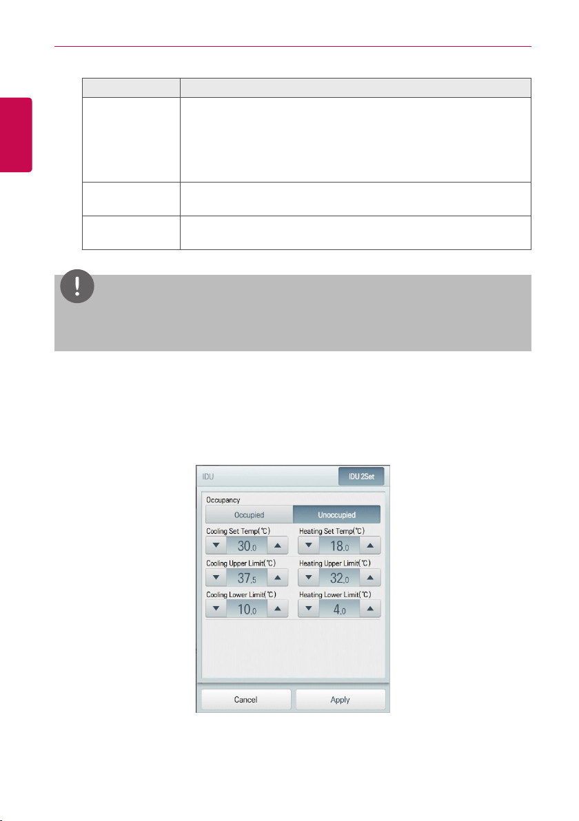
• Indoor 2Setpoint(2Set Auto Mode –US Only Option)
In the detail control window of the 2set indoor unit, touch [IDU 2Set] button, and in the
displayed automatic control setting window, you can set the automatic control.
The composition and functions of the automatic control menu are as follows.
25
ENGLISH
USING THE PROGRAM
Item Description
Occupancy
Set to occupied or unoccupied to change the room temperature
depending on the room occupancy.
y [Occupied] Button : Set to Occupied
y [Unoccupied] Button : Set to Unoccupied
Cooling Set Temp Click(Touch) [▲] /[▼] to set the cooling start temperature.
Cooling Upper
Limit
Click(Touch) [▲]/[▼] to set the cooling upper limit temperature range.
Cooling Lower
Limit
Click(Touch) [▲]/[▼] to set the cooling lower limit temperature range.
Heating Set Temp Click(Touch) [▲]/[▼] to set the heating start temperature.
Heating Upper
Limit
Click(Touch) [▲]/[▼] to set the heating upper limit temperature range.
Heating Lower
Limit
Click(Touch) [▲]/[▼] to set the heating lower limit temperature range.
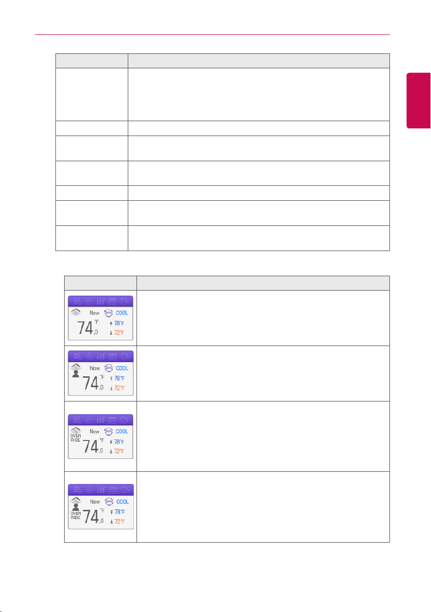
- 2Set Auto Mode Icon
Item Description
y The Icon as displayed in 2Set Auto Mode Option.
y Note: If the operation mode is ‘AUTO’, Cooling Set Temp(Blue)
and Heating Set Temp(Orange) is shown. In other operation
mode, only one Set Temp is shown.
If the occupancy is ‘Occupied’, a human shape is shown.
If ‘OVERRIDE’ is set on the remote control, OVERRIDE text is
shown.
(OVERRIDE function allows you to switch the occupancy status
(Occupied/Unoccupied) regardless of scheduled or set-up time. For
further information about OVERRIDE function, please refer to the
remote controller’s manual.)
If the occupancy is ‘Occupied’ and ‘OVERRIDE’ is set on the remote
control, a human shape and OVERRIDE text is shown.
(OVERRIDE function allows you to switch the occupancy status
(Occupied/Unoccupied) regardless of scheduled or set-up time. For
further information about OVERRIDE function, please refer to the
remote controller’s manual.)

26
ENGLISH
USING THE PROGRAM
NOTES
y
2Set Auto Mode function is only available for the U.S.
y
This function is activated only when Auto Mode Option is 2Set Auto Mode(US Only Option) and
IDU, ODU supports 2set function. (For further information about whether the device supports
the 2set function, please refer to the device’s manual.)
y
Under 2Set Auto mode, operation mode(cool, heat) status of the actual product is displayed
along with Auto icon.
NOTES
y
ACS IV Controllers’s control command is above the occupancy sensor connected to the IDU.
y
When Occupancy is changed, Cooling Set Temp, Heating Set Temp is changed to the recent
Schedule’s Set Temp. If there was no schedule, Cooling Set Temp, Heating Set Temp is set to
the default.
(Example)
When the schedules were set up as follows,
09AM – 12 PM: Occupied / Cooling Set Temp 80°F / Heating Set Temp 64°F
12PM – 13 PM: Unoccupied / Cooling Set Temp 84°F / Heating Set Temp 60°F
13PM – 15 PM: Occupied / Cooling Set Temp 78°F / Heating Set Temp 66°F
after 15PM
if the room is occupied, Cooling Set Temp is 78°F and Heating Set Temp 66°F.
If the room is unoccupied, Cooling Set Temp is 84°F and Heating Set Temp 60°F.
y
IDU can be set to Occupied ON, Occupied OFF, Unoccupied ON & Unoccupied OFF. When
IDU is controlled OFF neither Heating, Cooling or Fan operation can occur.
27
ENGLISH
USING THE PROGRAM
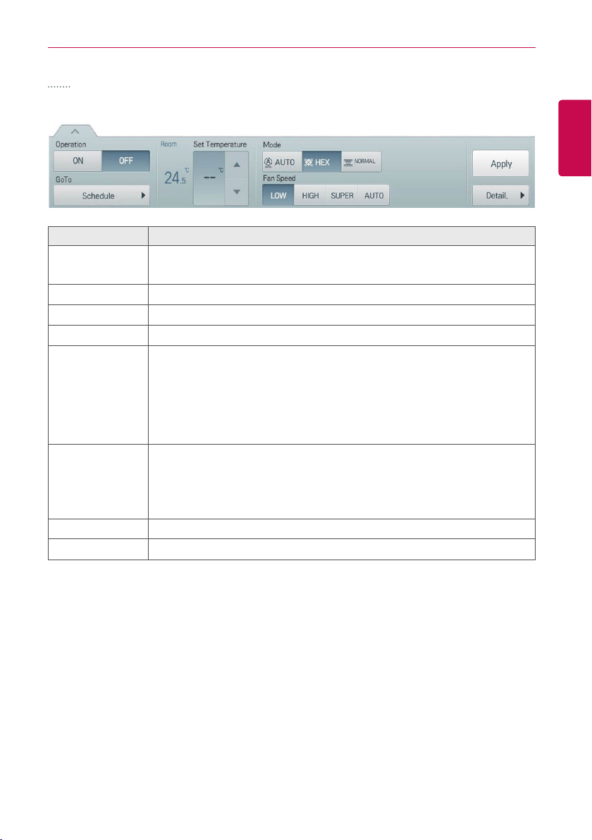
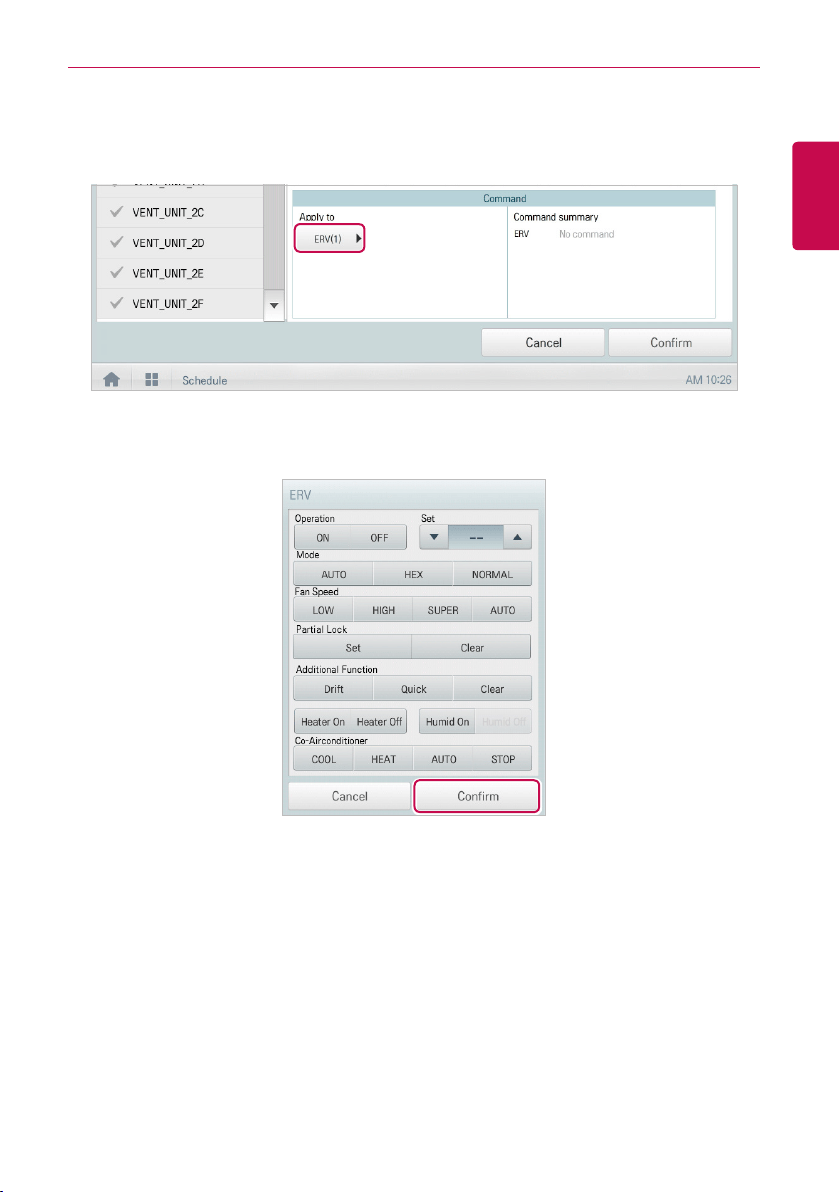
ERV
The following is the ERV control menu and features.
Item Description
Operation
y [ON] Button: Starts the operation of the device.
y [OFF] Button: Stops the operation of the device.
GoTo
[Schedule▶] Button: Move to Schedule menu.
Room Display the current temperature.
Set Temperature Click(Touch) [▲]/[▼] to set a desired temperature (the ERV is not activated).
Mode
y [AUTO] Button: Evaluates the operating environment conditions and
automatically sets the optimum temperature.
y [HEX] Button: Air supply and emissions are all ventilated through the heat
exchanger.
y [NORMAL] Button: Ventilate emissions without passing through the heat
exchanger.
Fan Speed
y [LOW] Button: Slow fan speed.
y [HIGH] Button: Fast fan speed.
y [SUPER] Button: Maximum fan speed.
y [AUTO] Button: Loops from low to high to super fan speeds.
[Apply] Button Apply control menu setting to the device
[Detail. ▶] Button
Control details.
28
ENGLISH
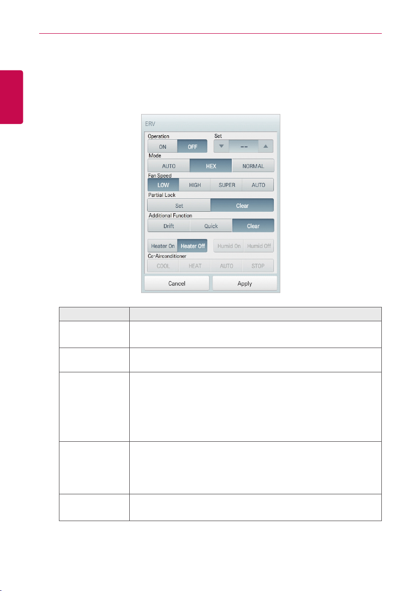
USING THE PROGRAM
• ERV Fine Control
In the control menu of the ventilation, touch [Detail. ▶] button, and in the displayed detail
control window, you can control detail items. The composition and functions of the detail menu
are as follows.
Item Description
Operation
y [ON] Button: Starts the operation of the device.
y [OFF] Button: Stops the operation of the device.
Set
Click(Touch) [▲]/[▼] to set a desired temperature (the ERV is not
activated).
Mode
y [AUTO] Button: Evaluates the operating environment conditions and
automatically sets the optimum temperature.
y [HEX] Button: Air supply and exhaust are all ventilated through the
heat exchanger.
y [NORMAL] Button: Exhaust AIR does not pass through the heat
exchanger.
Fan Speed
y [LOW] Button: Slow fan speed.
y [HIGH] Button: Fast fan speed.
y [SUPER] Button: Maximum fan speed.
y [AUTO] Button: Loops from low to high to super fan speeds.
Partial Lock
y [Set] Button: Disables remote control for all features.
y [Clear] Button: Disable the lock.
29
ENGLISH
USING THE PROGRAM
Item Description
Additional
Function
y [Drift] Button: Reduces energy consumption by operating in the
most efficient method possible.
y [Quick] Button: Operates at maximum performance.
y [Clear] Button: Disables power saving / rapid operation.
y [Heater On] Button: Enables the heater function to heat the room.
y [Heater Off] Button: Disables the heater function.
Some additional function might not be provided according to your
country such as U.S.
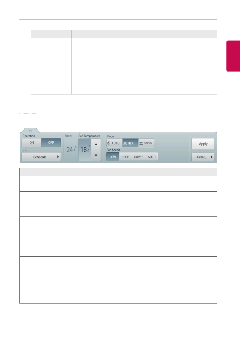
ERV DX
The following is the ERV DX control menu and features.
Item Description
Operation
y [ON] Button: Starts the operation of the device.
y [OFF] Button: Stops the operation of the device.
GoTo
[Schedule▶] Button: Move to Schedule menu.
Room Display the current temperature.
Set Temperature Click(Touch) [▲]/[▼] to set the temperature.
Mode
y [AUTO] Button: Evaluates the operating environment conditions and
automatically sets the optimum temperature.
y [HEX] Button: Air supply and emissions are all ventilated through the heat
exchanger.
y [NORMAL] Button: Ventilate emissions without passing through the heat
exchanger.
Fan Speed
y [LOW] Button: Slow fan speed.
y [HIGH] Button: Fast fan speed.
y [SUPER] Button: Maximum fan speed.
y [AUTO] Button: Loops from low to high to super fan speeds.
[Apply] Button Apply control menu setting to the device
[Detail. ▶] Button
Control details.
30
ENGLISH
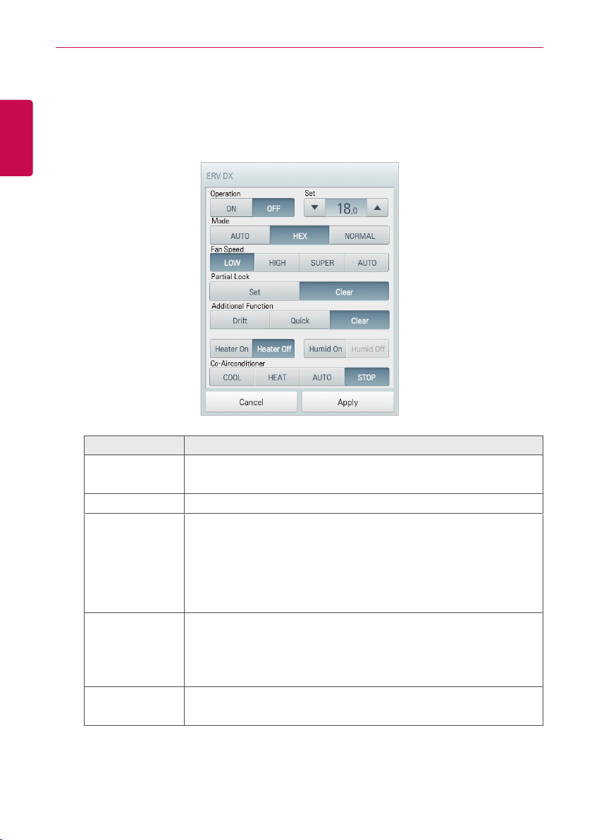
USING THE PROGRAM
• ERV DX Fine Control
In direct cooling ventilation control menu, touch [Detail. ▶] button, and in the displayed detail
control window, you can control detail items. The composition and functions of the detail menu
are as follows.
Item Description
Operation
y [ON] Button: Starts the operation of the device.
y [OFF] Button: Stops the operation of the device.
Set Click(Touch) [▲]/[▼] to set the temperature.
Mode
y [AUTO] Button: Evaluates the operating environment conditions and
automatically sets the optimum temperature.
y [HEX] Button: Air supply and emissions are all ventilated through
the heat exchanger.
y [NORMAL] Button: Ventilate emissions without passing through the
heat exchanger.
Fan Speed
y [LOW] Button: Slow fan speed.
y [HIGH] Button: Fast fan speed.
y [SUPER] Button: Maximum fan speed.
y [AUTO] Button: Loops from low to high to super fan speeds.
Partial Lock
y [Set] Button: Disables remote control for all features.
y [Clear] Button: Disables the lock.

31
ENGLISH
USING THE PROGRAM
Item Description
Additional
Function
y [Drift] Button: Reduces energy consumption by operating in the
most efficient method possible.
y [Quick] Button: Operates at maximum performance to prevent the
room's contaminated or humid air from entering other spaces.
y [Clear] Button: Disables power saving / rapid operation.
y [Heater On] Button: Enables the heater function to heat the room.
y [Heater Off] Button: Disables the heater function.
y [Humid On] Button: Enables the humidifier function for room humidity
control.
y [Humid Off] Button: Disable the humidifier function (not activated).
Some additional function might not be provided according to your
country such as U.S.
Co- Airconditioner
y [COOL] Button: Operates with Cooling Mode.
y [HEAT] Button: Operates with Heating Mode.
y [AUTO] Button: Operates in Auto Mode.
y [STOP] Button: Stops the air conditioning function.
32
ENGLISH
USING THE PROGRAM
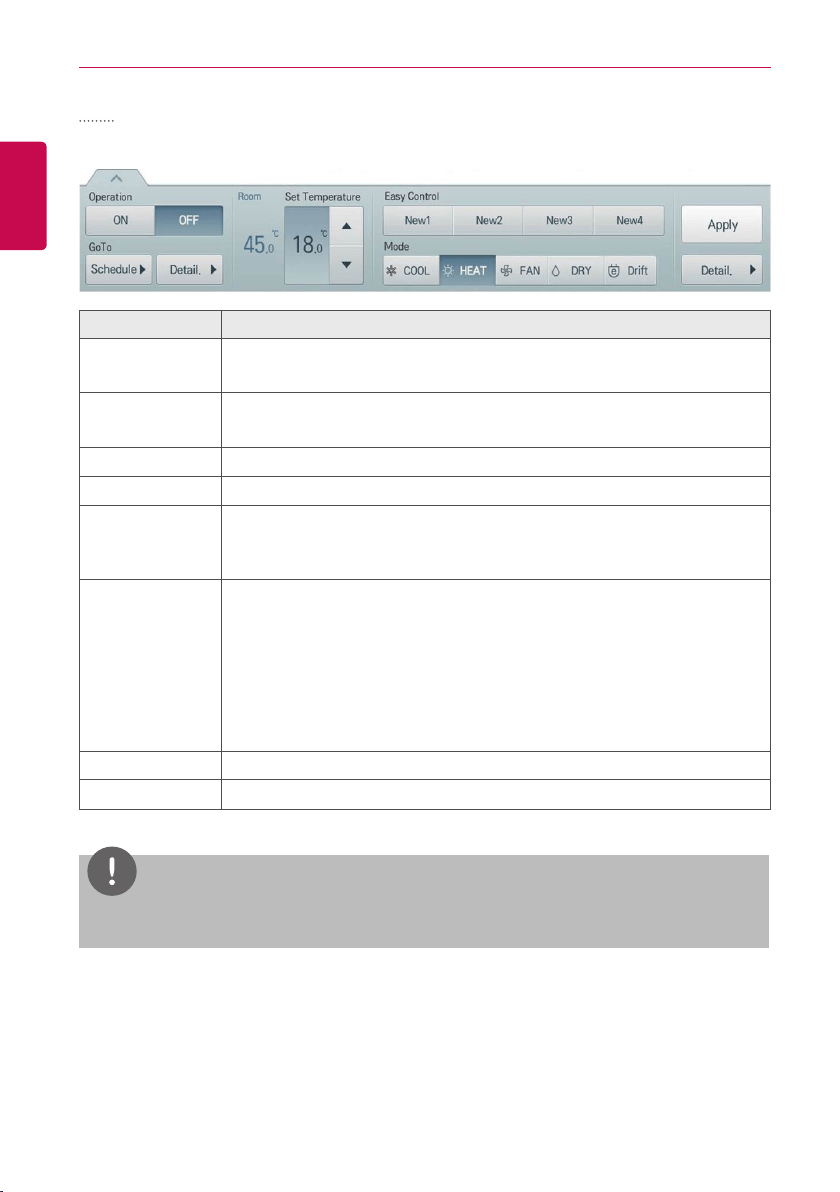
AHU
The following is the AHU control menu and features.
Item Description
Operation
y [ON] Button: Starts the operation of the device.
y [OFF] Button: Stops the operation of the device.
GoTo
y [Schedule▶] Button: Move to Schedule menu.
y [View Details ▶] button: Moves to detail information screen
Room Display the current temperature.
Set Temperature Click(Touch) [▲]/[▼] to set the temperature.
Easy control
y [Registered mode name] button: Check/edit control values of the
registered mode
y [New] button: Add new mode
Mode
y [COOL] Button: Operates with Cooling Mode.
y [HEAT] Button: Operates with Heating Mode.
y [FAN] Button: Purifies the air.
y [DRY] Button: Dehumidifies the air during the rainy season or when
humidity is high.
y [Drift] Button: Reduces energy consumption by operating in the most
efficient method possible.
[Apply] Button Apply control menu setting to the device
[Detail. ▶] Button
Control details.
NOTES
AHU or Chiller's screen and menu may be different according to the actually interfaced product.
33
ENGLISH
USING THE PROGRAM
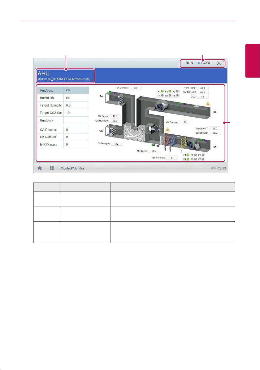
• View AHU details
In AHU control menu, touch [View Details ▶] button, and you can view detail information.
③
① ②
Number Item Description
①
Device information
Device information such as device name/status/
address, etc.
②
Status information
Status information such as operation/mode/
temperature, etc.
③
Detail information
Detail information such as automatic ventilation/
humidification operation/set humidity/set CO₂
concentration/lock all/damper open, etc.
34
ENGLISH
USING THE PROGRAM
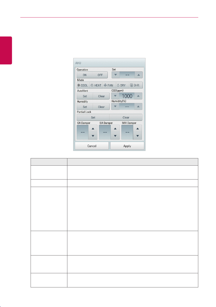
• AHU Fine Control
In AHU control menu, touch [Detail. ▶] button, and in the displayed detail control window, you
can control detail items.
The composition and functions of the detail menu are as follows.
Item Description
Operation
y [ON] Button: Starts the operation of the device.
y [OFF] Button: Stops the operation of the device.
Set Click(Touch) [▲]/[▼] to set the temperature.
Mode
y [COOL] Button: Operates with Cooling Mode.
y [HEAT] Button: Operates with Heating Mode.
y [FAN] Button: Purifies the air.
y [DRY] Button: Dehumidifies the air during the rainy season or when
humidity is high.
y [Drift] Button: Reduces energy consumption by operating in the
most efficient method possible.
AutoVent
y [Set] Button: If the CO₂ concentration level increases during cooling
or heating, increase the outdoor air volume to reduce the CO₂
concentration level.
y [Clear] Button: Disables AutoVent.
CO2(ppm)
Use [▲] /[▼] to set the desired carbon dioxide emission level from 500
ppm to 1,500 ppm in intervals of 100 ppm (CO₂ is not settable in some
models.).
Humidify
y [Set] Button: Enables the humidifier function.
y [Clear] Button: Disables the humidifier function.
35
ENGLISH
USING THE PROGRAM
Item Description
Humidity(%)
Use [▲] /[▼] to set the desired humidity from 30% to 80% in intervals
of 1%.
Partial Lock
y [Set] Button: Disables remote control for all features.
y [Clear] Button: Disables the lock.
OA Damper Use [▲] /[▼] to set the OA damper from 0° to 90° in intervals of 1°.
EA Damper
Use [▲] /[▼] to set the EA damper openness from 0° to 90° in intervals
of 1°.
MIX Damper
Use [▲] /[▼] to set the mix damper openness from 0° to 90° in intervals
of 1°.
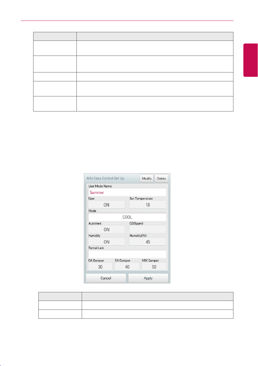
• AHU easy control
If you register frequently used control setting values with easy control in advance, you can eas-
ily control AHU.
- Registered easy control
In easy control, if you touch [Registered mode name (Example) Summer AM)] button, you
can check or edit the control values.
Item Description
[Modify] button Moves to the edit screen of the selected mode
[Delete] button Deletes the selected mode
36
ENGLISH
USING THE PROGRAM
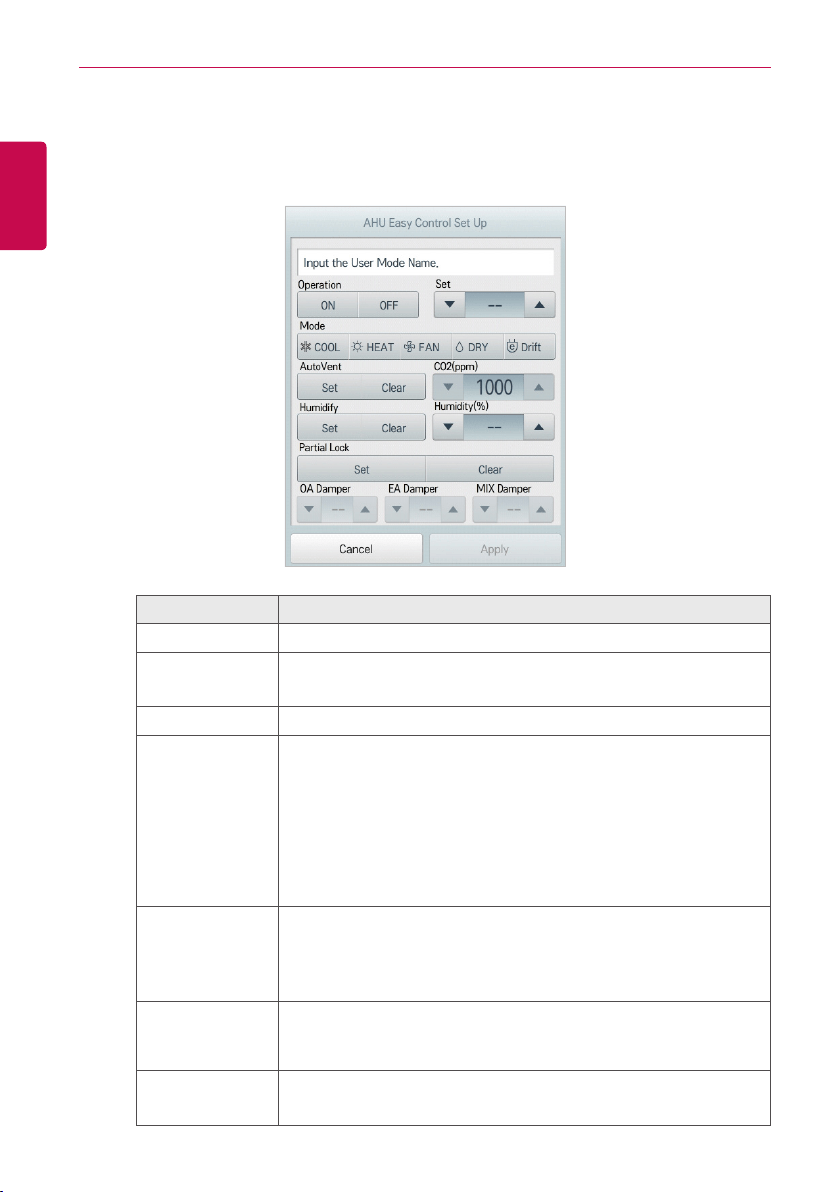
- New easy control registration
In easy control, if you touch [New] button, you can register new easy control. The composi-
tion and functions of the detail setting menu of easy control are as follows.
Item Description
User mode name Click(Touch) the input section, and input easy control name.
Operation
y [ON] Button: Starts the operation of the device.
y [OFF] Button: Stops the operation of the device.
Set Click(Touch) [▲]/[▼] to set the temperature.
Mode
y [COOL] Button: Operates with Cooling Mode.
y [HEAT] Button: Operates with Heating Mode.
y [FAN] Button: Purifies the air.
y [DRY] Button: Dehumidifies the air during the rainy season or
when humidity is high.
y [Drift] Button: Reduces energy consumption by operating in the
most efficient method possible.
AutoVent
y [Set] Button: If the CO₂ concentration level increases during
cooling or heating, increase the outdoor air volume to reduce the
CO₂ concentration level.
y [Clear] Button: Disables AutoVent.
CO
2
(ppm)
Use [▲] /[▼] to set the desired carbon dioxide emission level from
500 ppm to 1,500 ppm in intervals of 100 ppm (CO₂ is not settable
in some models.).
Humidify
y [Set] Button: Enables the humidifier function.
y [Clear] Button: Disables the humidifier function.

37
ENGLISH
USING THE PROGRAM
Item Description
Humidity(%)
Use [▲] /[▼] to set the desired humidity from 30% to 80% in
intervals of 1%.
Partial Lock
y [Set] Button: Disables remote control for all features.
y [Clear] Button: Disables the lock.
OA Damper Use [▲] /[▼] to set the OA damper from 0° to 90° in intervals of 1°.
EA Damper
Use [▲] /[▼] to set the EA damper openness from 0° to 90° in
intervals of 1°.
MIX Damper
Use [▲] /[▼] to set the mix damper openness from 0° to 90° in
intervals of 1°.
38
ENGLISH
USING THE PROGRAM
Air-cooled scroll chiller, water-cooled scroll chiller
Air-cooled and water-cooled is separated according to the refrigerant (cooling in air: air, liquid-
cooled: water). Functions and menus are the same, but there is a difference in the range and set
temperature, etc.
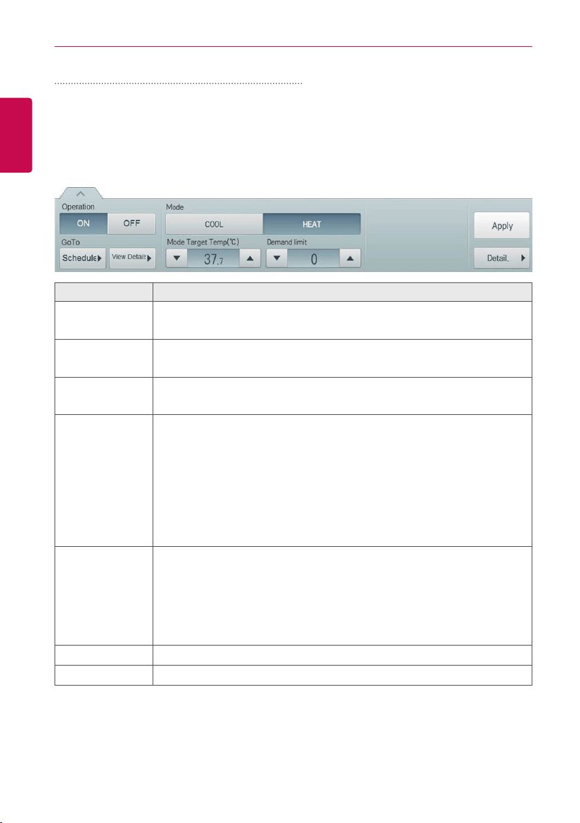
The following menu controls the configuration and function of the air-cooled scroll chiller, water-
cooled scroll chiller.
Item Description
Operation
y [ON] Button: Starts the operation of the device.
y [OFF] Button: Stops the operation of the device.
GoTo
y [Schedule ▶] Button: Move to Schedule menu.
y [View Details ▶] button: Moves to detail information screen.
Mode
y [COOL] Button: Operates with Cooling Mode.
y [HEAT] Button: Operates with Heating Mode.
Mode Target
Temp (℃)
Click(Touch) [▲]/[▼] to set the mode set temperature.
y Air-cooled scroll chiller
- COOL: 5 ℃~15 ℃
- HEAT: 35 ℃~55 ℃
y water-cooled scroll chiller
- COOL: 5 ℃~15 ℃
- HEAT: 40 ℃~57 ℃
Demand limit
As measured at 1minute intervals the power consumption of the refrigerator,
the current power consumption does not exceed a target power consumption,
demand rate limit, function to lower the operation rate of the current.
Click(Touch) the [▲] / [▼] button to set a limit on the rate of demand.
y air-cooled scroll chiller: 0~120 (10 units)
y water-cooled scroll chiller: 0, 30~120 (10 units)
[Apply] Button Apply control menu setting to the device.
[Detail. ▶] Button
Controls details.
39
ENGLISH
USING THE PROGRAM
NOTES
y
Chiller is optional. It can be activated by installing additional CHILLER OPTION program.
y
Chiller displays Celsius only.
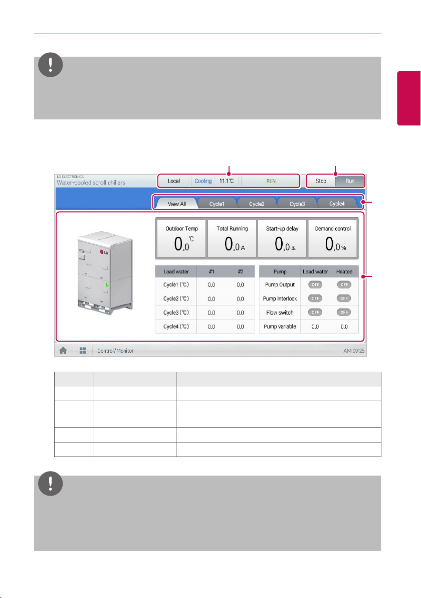
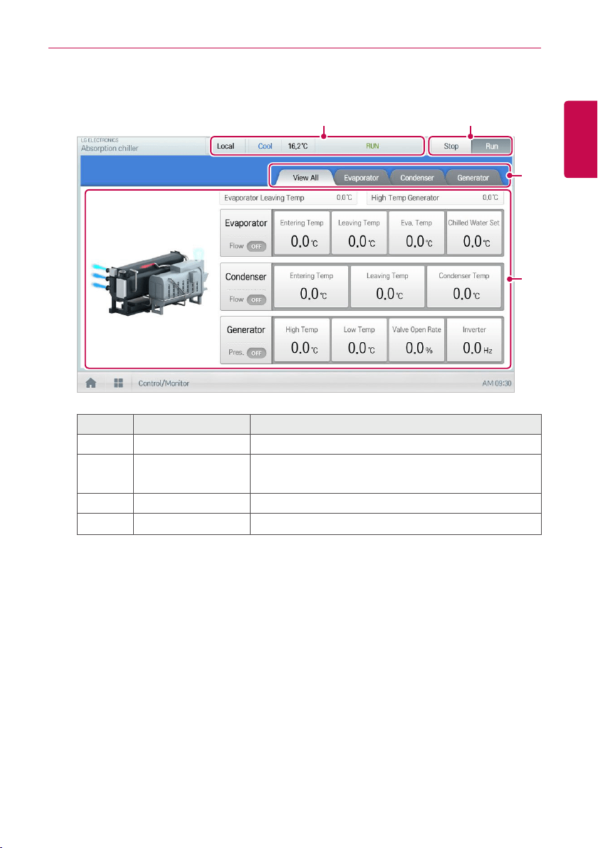
• View Water-cooled scroll chiller Details
You can find detailed information, touch [Detail ▶] button on the control menu, scroll chillers.
① ②
③
④
Number Item Description
①
Status information Status information, such as mode/temperature/operation.
②
Operation status
y [OFF] Button: Stops the operation of the device.
y [ON] Button: Starts the operation of the device.
③
View each Tab View ALL/View Each are Displayed as a tab.
④
Detail information Cycle Details.
NOTES
Four-wayvalveisusedforswitchingthecooling↔heating.Wasnotappliedtotheelectriccoil
during cooling, but the role that emit heat and by applying an electric when the heating. The
four-way valve, it exists only in the cold / heating combined model, in the case of a cooling only
model, the four-way valve information is not provided.
40
ENGLISH
USING THE PROGRAM
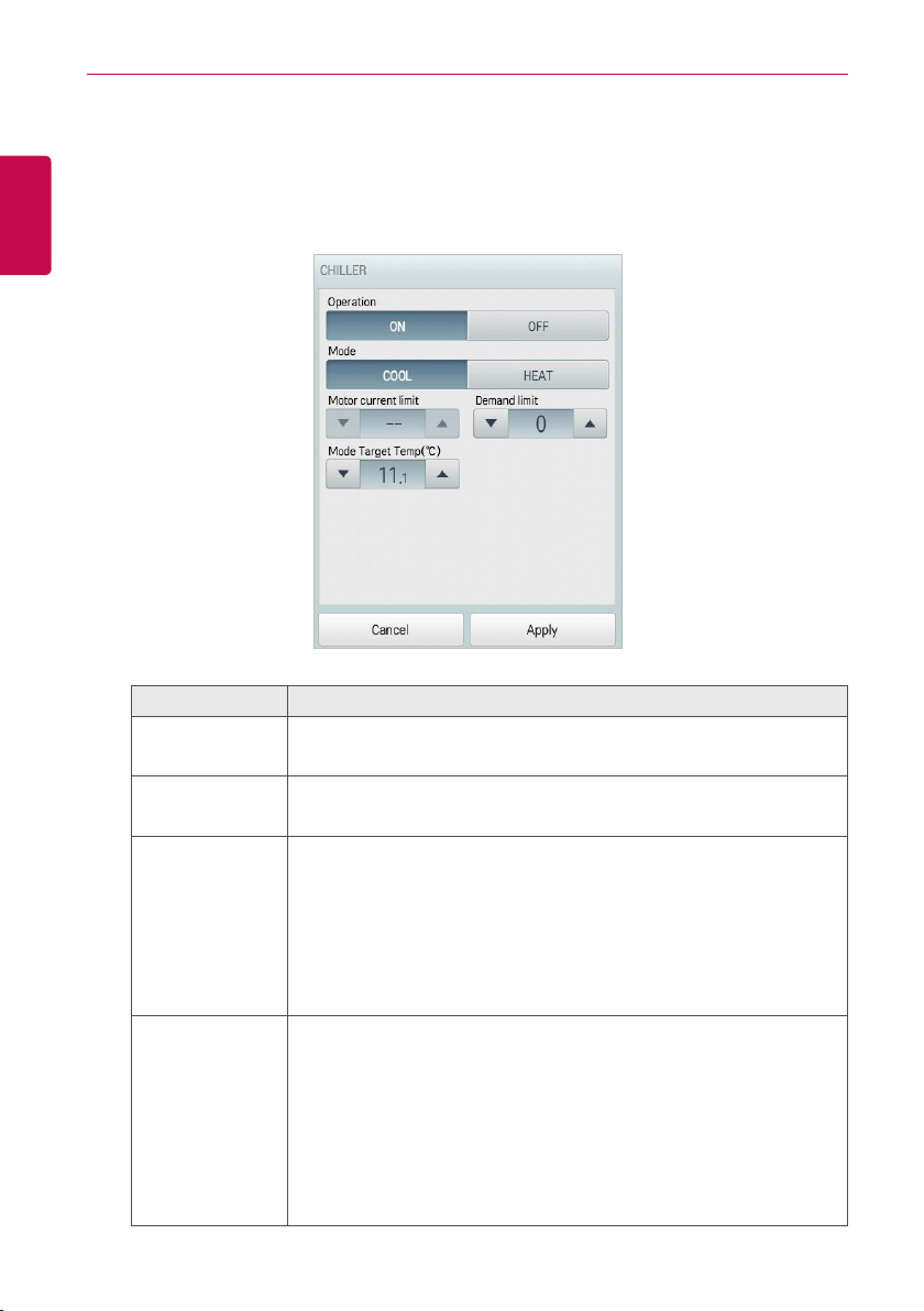
• Water-cooled scroll chiller Fine Control
You can control the details in the detail control window that appears when you touch the [Detail
control ▶] button on the control menu of the scroll chiller. Configuration and functions of the
Advanced menu is as follows.
Item Description
Operation
y [ON] Button: Starts the operation of the device.
y [OFF] Button: Stops the operation of the device.
Mode
y [COOL] Button: Operates with Cooling Mode.
y [HEAT] Button: Operates with Heating Mode.
Demand limit
As measured at 1minute intervals the power consumption of the
refrigerator, the current power consumption does not exceed a target
power consumption, demand rate limit, function to lower the operation
rate of the current. Click(Touch) the [▲] / [▼] button to set a limit on the
rate of demand.
y air-cooled scroll chiller: 0~120 (10 units)
y water-cooled scroll chiller: 0, 30~120 (10 units)
Mode Target
Temp
Click(Touch) [▲]/[▼] to setting of the Mode set temperature.
y Air-cooled scroll chiller
- COOL: 5 ℃~15 ℃
- HEAT: 35 ℃~55 ℃
y water-cooled scroll chiller
- COOL: 5 ℃~15 ℃
- HEAT: 40 ℃~57 ℃
41
ENGLISH
USING THE PROGRAM
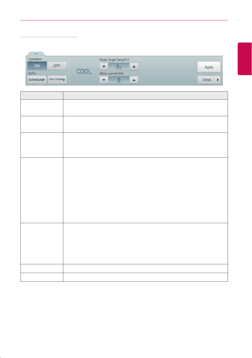
Turbo chiller, Screw chiller
The following menu controls the configuration and function of the Turbo chiller, Screw chiller.
Item Description
Operation
y [ON] Button: Starts the operation of the device.
y [OFF] Button: Stops the operation of the device.
GoTo
y [Schedule ▶] Button: Move to Schedule menu.
y [View Details ▶] button: Moves to detail information screen.
Mode
(not activated)
y Turbo chiller : Cool/Heat/Ice
y Screw chiller : Cool/Ice
Mode Target
Temp (℃)
Click(Touch) [▲]/[▼] to setting of the Mode set temperature.
y Turbo chiller
- Cool: 3 °C ~ 50 °C
- Heat: 10 °C ~ 90 °C
- Ice: -20 °C ~ 30 °C
y Screw chiller
- Cool: 3 °C ~ 50 °C
- Ice: -20 °C ~ 30 °C
Motor current
limit
Since the constant current is greater than that of the motor flows, there can
affect (such as temperature bearing temperature, the motor windings R)
ambient temperature sensor, the motor current limit, setting the current limit
for the load to prevent function.
Click(Touch) [▲]/[▼] to setting the motor current limit within the range of 1 to
100%.
[Apply] Button Apply control menu setting to the device.
[Detail. ▶] Button
Controls details.
42
ENGLISH
USING THE PROGRAM
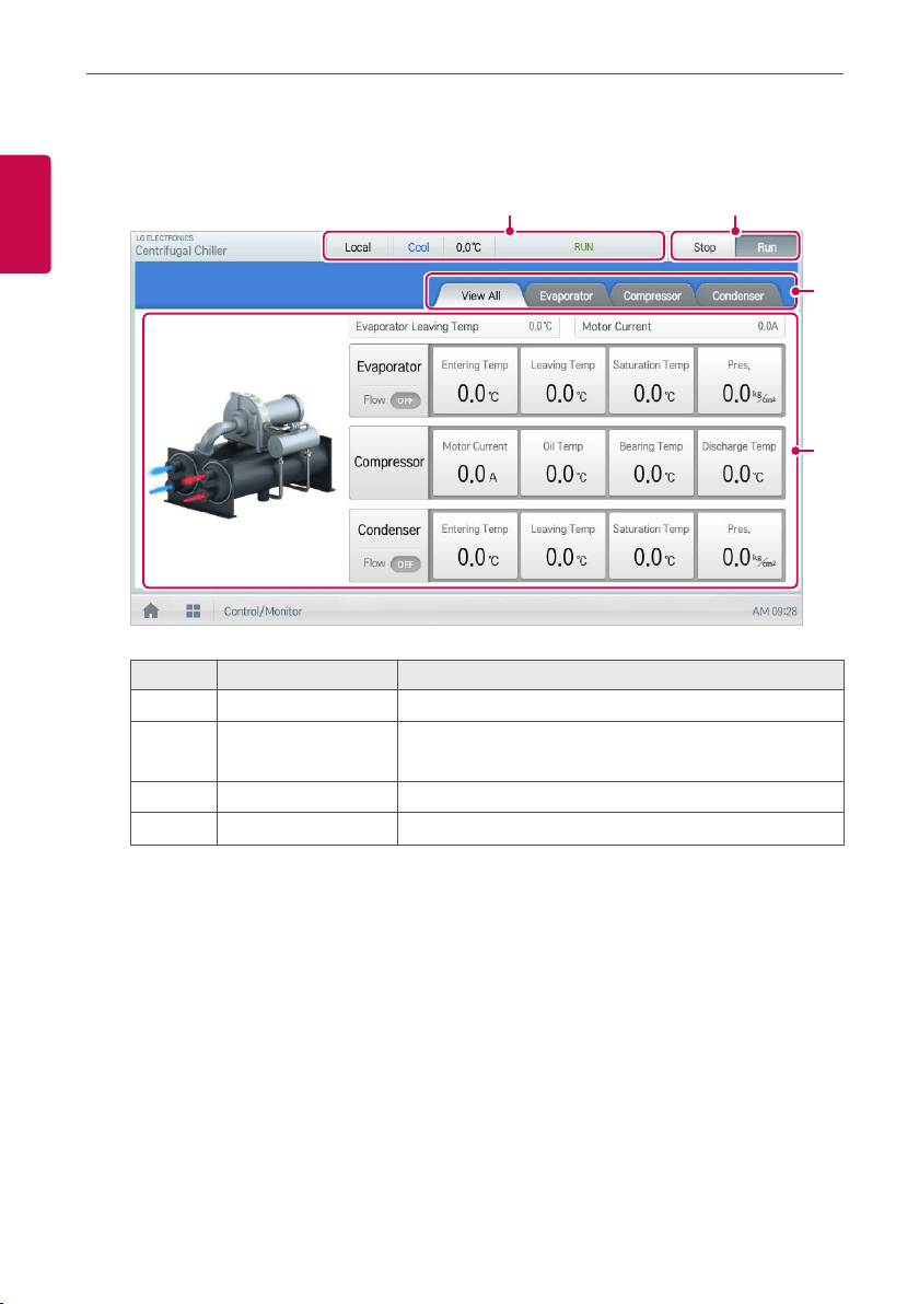
• View Turbo chiller, Screw chiller Details
You can find detailed information, touch [Detail ▶] button on the control menu, Turbo chillers,
Screw chiller.
① ②
③
④
Number Item Description
①
Status information Status information, such as mode/temperature/operation.
②
Operation status
y [OFF] Button: Stops the operation of the device.
y [ON] Button: Starts the operation of the device.
③
View each Tab View ALL/View Each are Displayed as a tab.
④
Detail information evaporator/compressor/condenser Details.
43
ENGLISH
USING THE PROGRAM
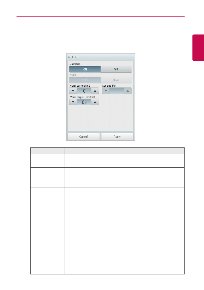
• Turbo chiller, Screw chiller Fine Control
You can control the details in the detail control window that appears when you touch the [Detail
control ▶] button on the control menu of the Turbo chiller, Screw chiller . Configuration and
functions of the Advanced menu is as follows.
Item Description
Operation
y [ON] Button: Starts the operation of the device.
y [OFF] Button: Stops the operation of the device.
Mode
(not activated)
y [COOL] Button: Operates with Cooling Mode.
y [HEAT] Button: Operates with Heating Mode.
Motor current
limit
Since the constant current is greater than that of the motor flows,
there can affect (such as temperature bearing temperature, the motor
windings R) ambient temperature sensor, the motor current limit,
setting the current limit for the load to prevent function.
Click(Touch) [▲]/[▼] to setting the motor current limit within the
range of 1 to 100%.
Mode Target
Temp (℃)
Click(Touch) [▲]/[▼] to setting of the Mode set temperature.
y Turbo chiller
- Cool: 3 °C ~ 50 °C
- Heat: 10 °C ~ 90 °C
- Ice: -20 °C ~ 30 °C
y Screw chiller
- Cool: 3 °C ~ 50 °C
- Ice: -20 °C ~ 30 °C
44
ENGLISH
USING THE PROGRAM
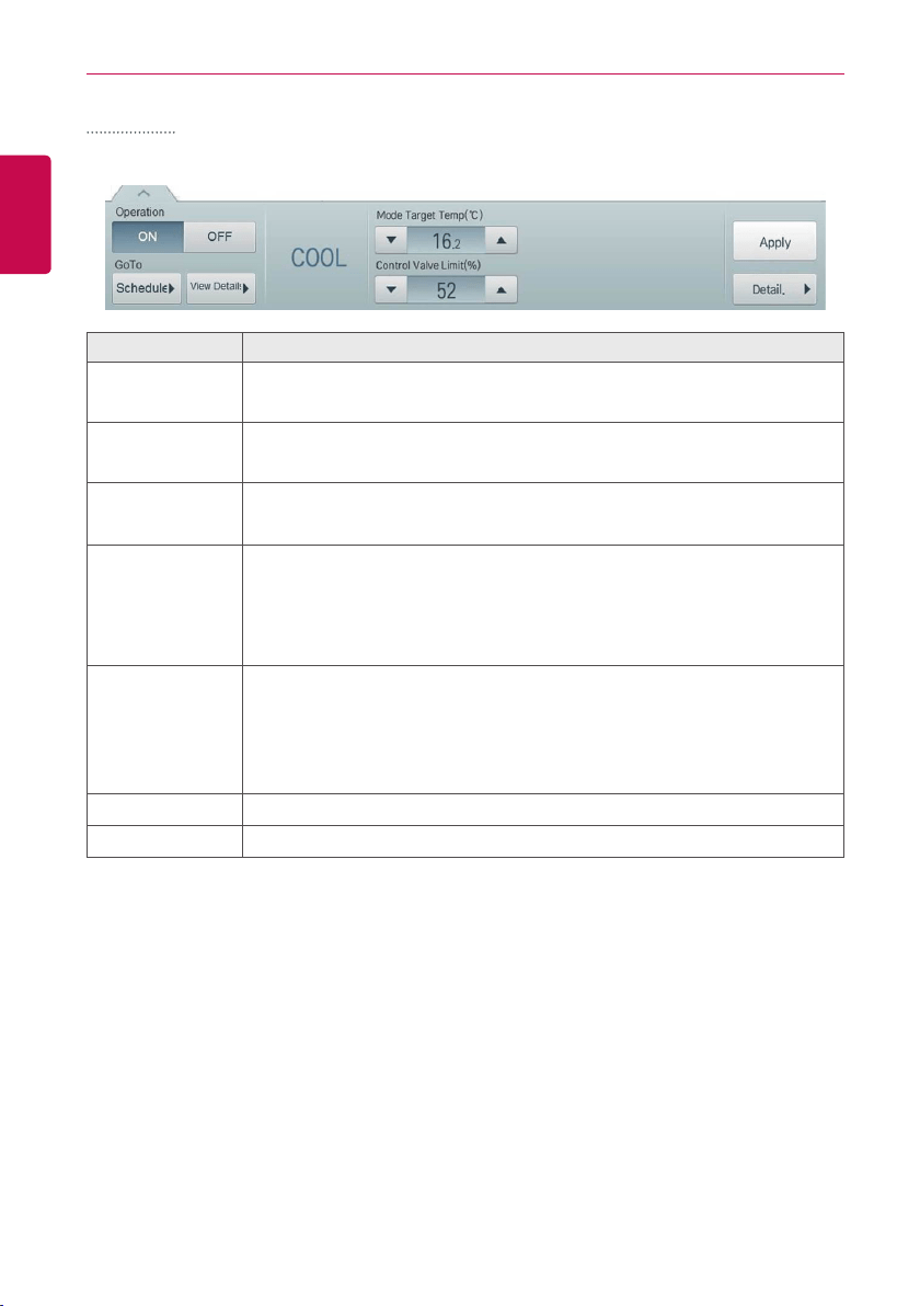
ABS chiller
The following menu controls the configuration and function of the ABS chiller.
Item Description
Operation
y [ON] Button: Starts the operation of the device.
y [OFF] Button: Stops the operation of the device.
GoTo
y [Schedule ▶] Button: Move to Schedule menu.
y [View Details ▶] button: Moves to detail information screen.
Mode
(not activated)
y ABS chiller: Cool/Heat
Mode Target
Temp (°C)
Click(Touch) [▲]/[▼] to setting of the Mode set temperature.
y ABS chiller
- Cool: 3 °C ~ 20 °C
- Heat: 40 °C ~ 80 °C
Control Valve
Limit
Function to maintain the cycle by limiting the heat source inlet calories at
chiller operation. Heat input so that it will not be any more to set the maximum
value of the control valve (%).
Click(Touch) [▲]/[▼] to setting the Control valve limit within the range of 0 to
100%.
[Apply] Button Apply control menu setting to the device.
[Detail. ▶] Button
Controls details.
45
ENGLISH
USING THE PROGRAM
• View ABS chiller Details
You can find detailed information, touch [Detail ▶] button on the control menu, ABS chillers.
① ②
③
④
Number Item Description
①
Status information Status information, such as mode/temperature/operation.
②
Operation status
y [OFF] Button: Stops the operation of the device.
y [ON] Button: Starts the operation of the device.
③
View each Tab View ALL/View Each are Displayed as a tab.
④
Detail information evaporator/compressor/condenser Details.
46
ENGLISH
USING THE PROGRAM
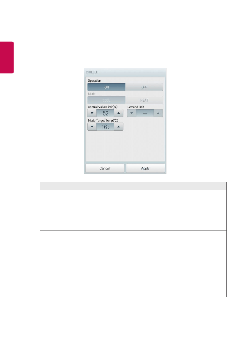
• ABS chiller Fine Control
You can control the details in the detail control window that appears when you touch the [Detail
control ▶] button on the control menu of the ABS chiller . Configuration and functions of the
Advanced menu is as follows.
Item Description
Operation
y [ON] Button: Starts the operation of the device.
y [OFF] Button: Stops the operation of the device.
Mode
(not activated)
y [COOL] Button: Operates with Cooling Mode.
y [HEAT] Button: Operates with Heating Mode.
Control Valve
Limit
Function to maintain the cycle by limiting the heat source inlet
calories at chiller operation. Heat input so that it will not be any more
to set the maximum value of the control valve (%).
Click(Touch) [▲]/[▼] to setting the Control valve limit within the range
of 0 to 100%.
Mode Target
Temp (℃)
Click(Touch) [▲]/[▼] to setting of the Mode set temperature.
y ABS chiller
- Cool: 3 °C ~ 20 °C
- Heat: 40 °C ~ 80 °C
47
ENGLISH
USING THE PROGRAM
DOKIT
The following is the DOKIT control menu and features.
Item Description
Operation
y [ON] Button: Starts the operation of the device.
y [OFF] Button: Stops the operation of the device.
GoTo
[Schedule▶] Button: Move to Schedule menu.
[Apply] Button Apply control menu setting to the device
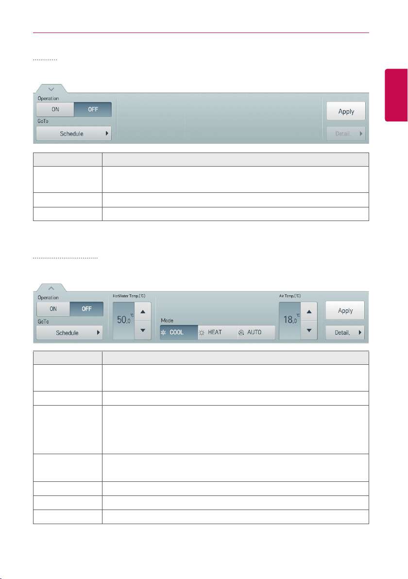
AWHP / Hydro Kit
The following is the AWHP/Hydro Kit control menu and features.
Item Description
Operation
y [ON] Button: Starts the operation of the device.
y [OFF] Button: Stops the operation of the device.
GoTo
[Schedule▶] Button: Move to Schedule menu.
Mode
y [AUTO] Button: Evaluates the operating environment conditions and
automatically sets the optimum temperature.
y [COOL] Button: Operates with Cooling Mode.
y [HEAT] Button: Operates with Heating Mode.
Air Temp./
Water Temp.
(Indicated as air or water temperature depending on the product.)
Click(Touch) [▲]/[▼] to set the air/water temperature.
HotWater Temp. Click(Touch) [▲]/[▼] to set the water heater temperature.
[Apply] Button Apply control menu setting to the device
[Detail. ▶] Button
Control details.
48
ENGLISH
USING THE PROGRAM
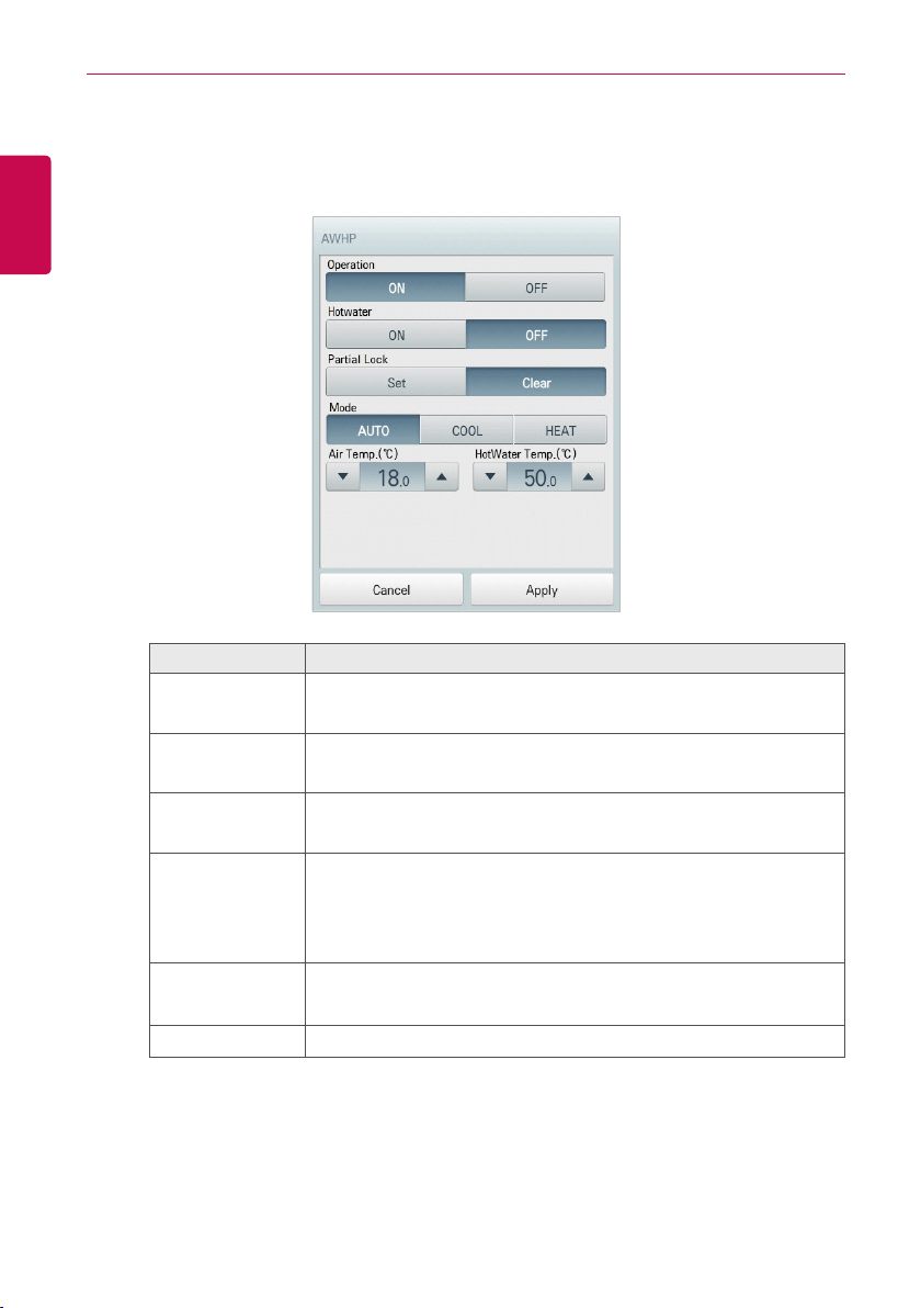
• AWHP and Hydrokit Fine Control
In AWHP control menu, touch [Detail. ▶] button, and in the displayed detail control window,
you can control detail items. The composition and functions of the detail menu are as follows.
Item Description
Operation
y [ON] Button: Starts the operation of the device.
y [OFF] Button: Stops the operation of the device.
Hotwater
y [ON] Button: Enables the hot water function.
y [OFF] Button: Disables the hot water function.
Partial Lock
y [Set] Button: Disables remote control for all features.
y [Clear] Button: Disable the lock.
Mode
y [AUTO] Button: Evaluates the operating environment conditions
and automatically sets the optimum temperature.
y [COOL] Button: Operates with Cooling Mode.
y [HEAT] Button: Operates with Heating Mode.
Air Temp./
Water Temp.
(Indicated as air or water temperature depending on the product.)
Click(Touch) [▲]/[▼] to set the air/water temperature.
Hot Water Temp. Click(Touch) [▲]/[▼] to set the water heater temperature.
49
ENGLISH
USING THE PROGRAM
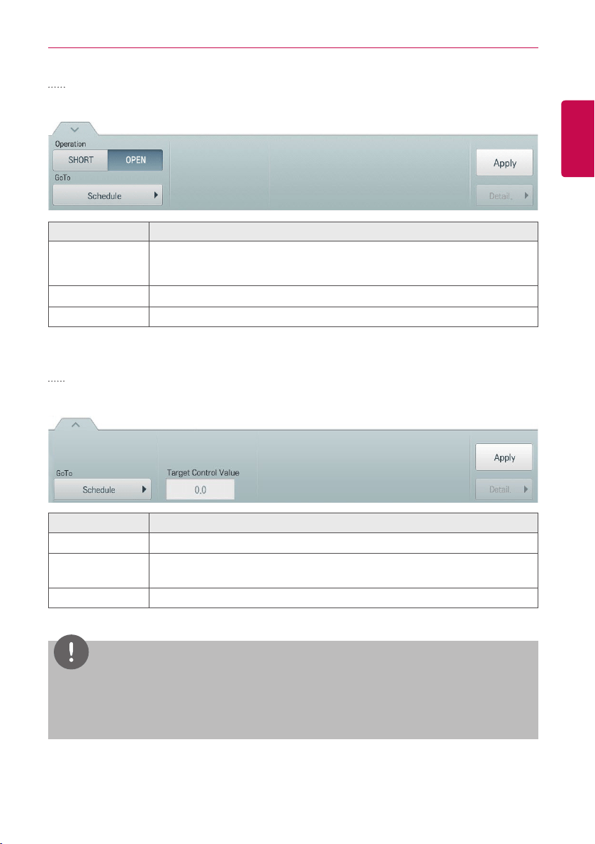
DO
The following is the DO control menu and features.
Item Description
Operation
y [SHORT] Button: Short signal output.
y [OPEN] Button: Open signal output.
GoTo
[Schedule▶] Button: Move to Schedule menu.
[Apply] Button Apply control menu setting to the device
AO
The following is the AO control menu and features.
Item Description
GoTo
[Schedule▶] Button: Move to Schedule menu.
Target Control
Value
Click(Touch) [▲]/[▼] to set the target control value.
[Apply] Button Apply control menu setting to the device
NOTES
y
Only when the usage set during device registration is the same, you can select multiple AO for
simultaneous control.
y
Input devices such as DI, UI, etc. are not available to control.
50
ENGLISH
USING THE PROGRAM
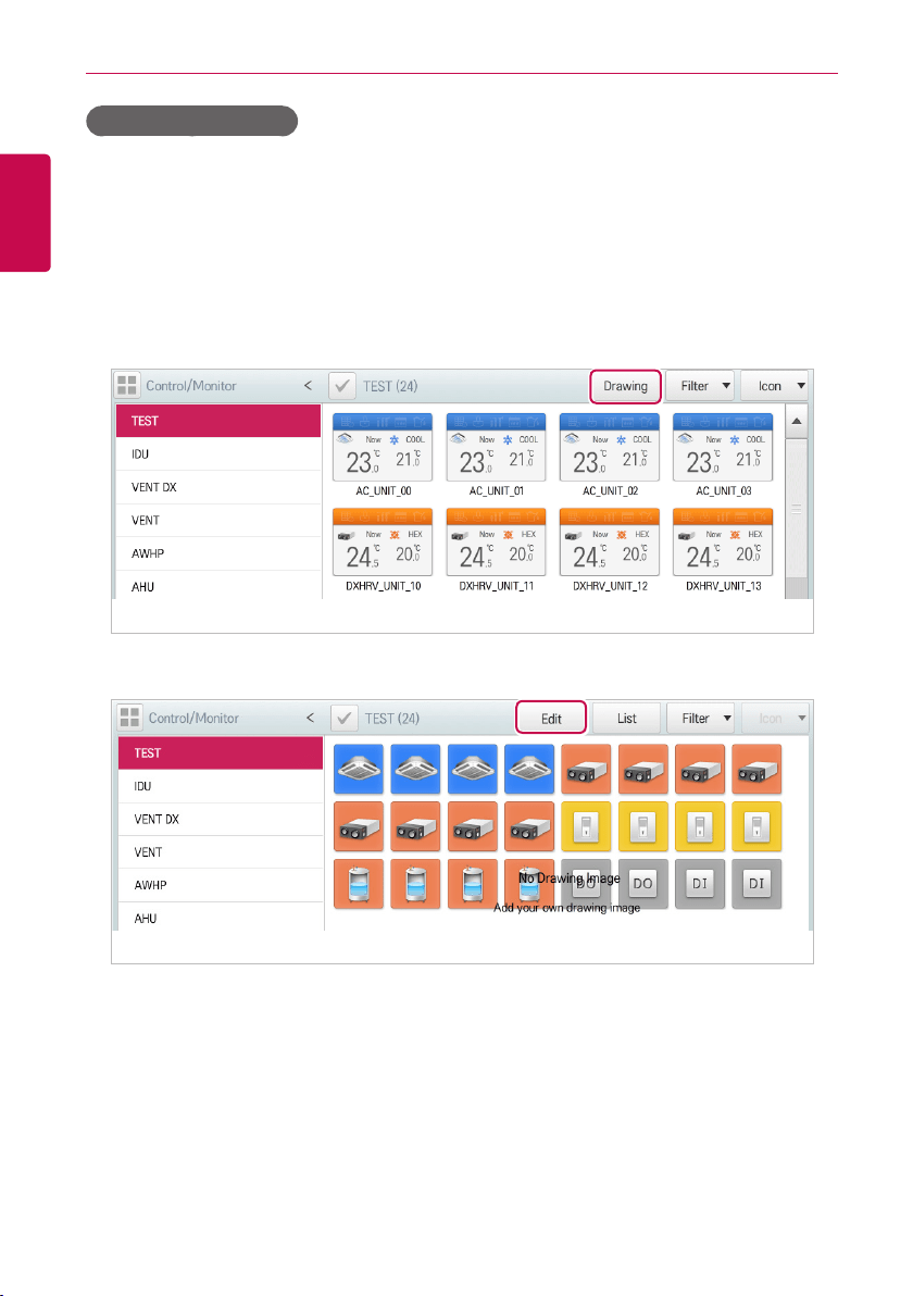
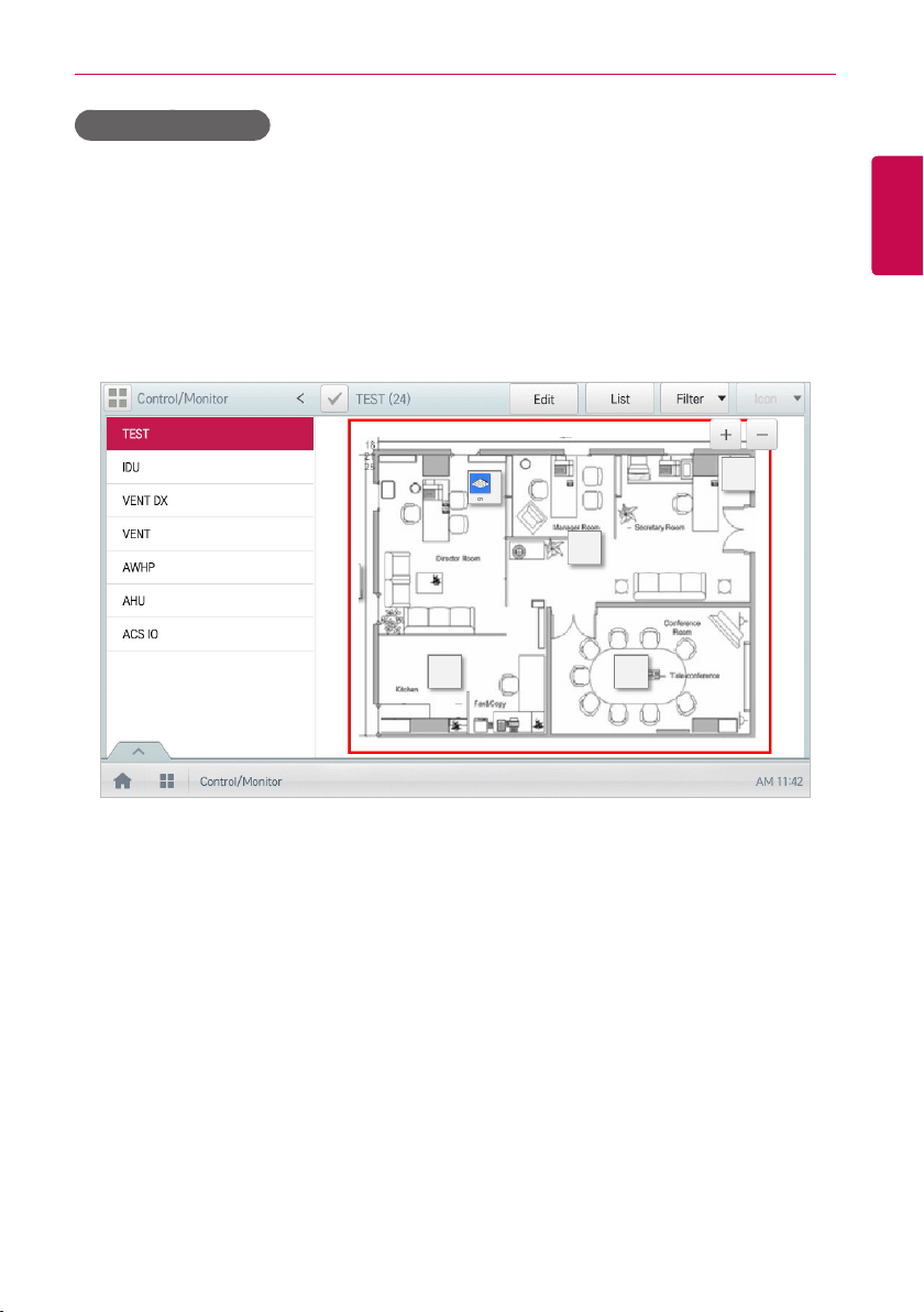
Registering Floor Plan
In the Control/Monitor menu, you can register floor plans to identify and locate each device and
device group. On the floor plan, you can register space information as well as the location where a
device is installed.
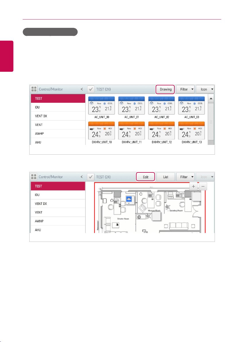
1. In the main menu, click(touch) the [Control/Monitor] menu icon.
2. Select the device group you want to monitor from the group list.
• The monitoring screen for the device is displayed.
3. Click(Touch) [Drawing] button.
4. Click(Touch) [Edit] button.
51
ENGLISH
USING THE PROGRAM
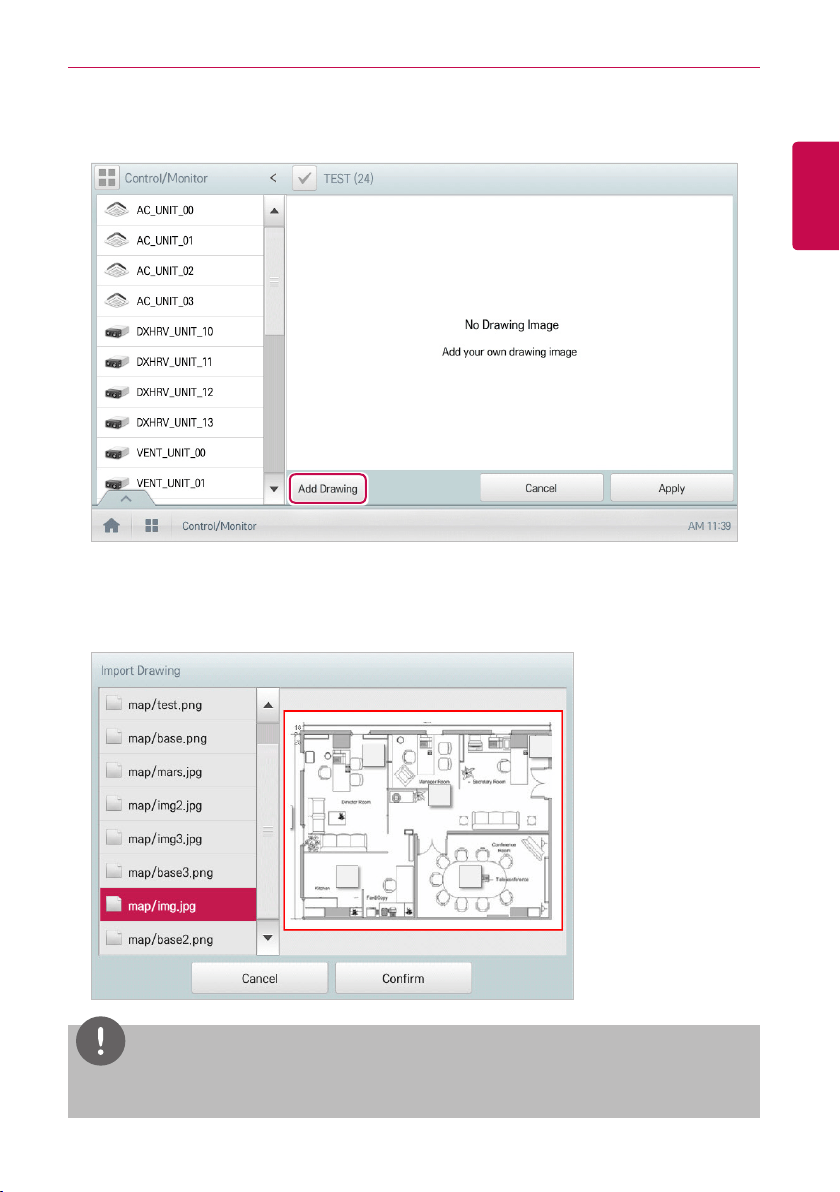
5. [Add Drawing] button.
• The Open Floor Plan window is displayed.
6. Select a desired floor plan from the Open Floor Plan window, then click(touch) the [Confirm]
button. (Valid file formats are: *.GIF, *.JPG, *.PNG.)
• The floor plan image is displayed.
NOTES
You cannot open a floor plan if the file name is in other languages. Use English file names only.
52
ENGLISH
USING THE PROGRAM
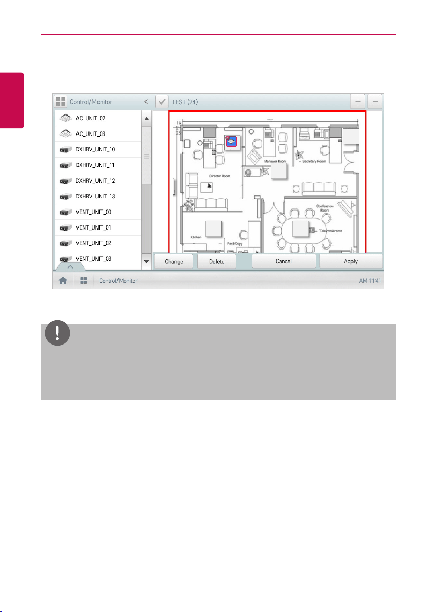
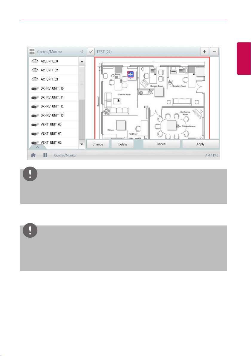
7. In the device list, select a device you want to display on the floor plan and click(touch) the device
location on the plan.
• To delete a device from the plan, double-click(touch) its icon.
8. To complete the registration of the floor plan, click(touch) the [Apply] button.
NOTES
y
To add a floor plan, put image file in USB root directory.
y
To add a floor plan, you can only use jpg, gif, or png file formats.
y
To add a floor plan, a 2MB or less image size is recommended.
53
ENGLISH
USING THE PROGRAM
Checking Floor Plan
In Control/Monitoring, you can check floor plans. On the floor plan, you can register space
information as well as the location where a device is installed.
1. In the main menu, click(touch) the [Control/Monitor] menu icon.
2. Select the device group you want to monitor from the group list.
• The monitoring screen for the device is displayed.
3. Click(Touch) [Drawing] button.
• The registered floor plan is displayed.
54
ENGLISH
USING THE PROGRAM
Editing the Floor Plan
You can edit a registered floor plan.
1. In the main menu, click(touch) the [Control/Monitor] menu icon.
2. Select the device group you want to monitor from the group list.
• The monitoring screen for the device is displayed.
3. Click(Touch) [Drawing] button.
4. Click(Touch) [Edit] button.
5. To change floor plan, click(touch) [Change] button.
• The Open Floor Plan window is displayed.
6. Select a desired floor plan from the Open Floor Plan window, then click(touch) the [Confirm]
button.
• The floor plan image is displayed.
55
ENGLISH
USING THE PROGRAM
7. To change the location of a device, click(touch) the icon of the device and then click(touch) the
location to which you want to move that device.
NOTES
You can select and drag the device to display on the drawing from the device list to add or
change location of the device.
8. To complete floor plan editing, click(touch) the [Apply] button.
NOTES
y
To add a floor plan, put image file in USB root directory.
y
To add a floor plan, you can only use jpg, gif, or png file formats.
y
To add a floor plan, a 2MB or less image size is recommended.
56
ENGLISH
USING THE PROGRAM
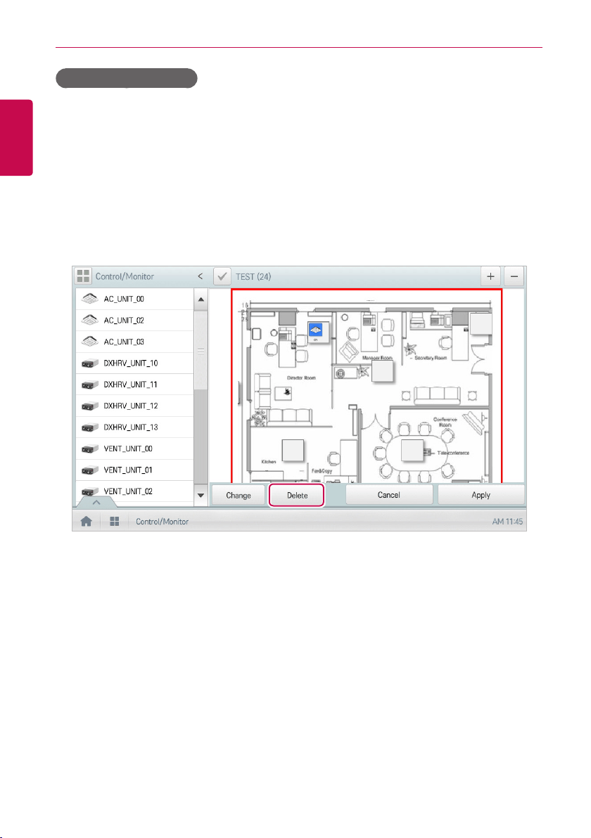
Deleting the Floor Plan
You can delete a registered floor plan.
1. In the main menu, click(touch) the [Control/Monitor] menu icon.
2. Select the device group you want to monitor from the group list.
• The monitoring screen for the device is displayed.
3. Click(Touch) [Drawing] button.
• The registered floor plan is displayed.
4. Click(Touch) [Edit] button.
5. To delete a floor plan, click(touch) the [Delete] button.
6. When you are prompted to confirm the deletion, click(touch) the [Confirm] button.
57
ENGLISH
USING THE PROGRAM
Monitoring a Device
You can check the control state of registered devices.
1. In the main menu, click(touch) the [Control/Monitor] menu icon.
2. Select the device group you want to monitor from the group list.
• The monitoring screen for the device is displayed.
3. Click(Touch) a device you want to monitor.
4. Please check the device information in the monitoring screen.
• The information on the monitoring screen differs depending on the view type. For details
about the view types, refer to View Type.
5. To check the control status of the device, click(touch) the [Detail. ▶] button.
58
ENGLISH
USING THE PROGRAM
Schedule
The Schedule feature allows you to program the behavior of the devices. If a device must adhere to a
certain schedule, you can program the device to operate only at scheduled times. Scheduled devices
do not activate unless programmed to do so and are managed centrally. This can significantly reduce
energy consumption. Schedules are event driven. This means that devices are controlled once at the
scheduled time.
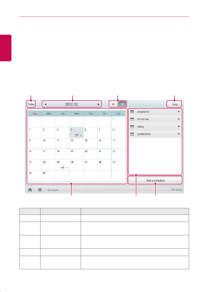
Schedule Screen composition and features
The following explains Schedule Screen composition and features.
①
⑤ ⑦⑥
② ③ ④
Number Item Description
①
[Today] Button Display today's date, the current week, or the current month.
②
Dates
y Displays the selected date.
y Use [◀]/[▶] to move to the previous/next date.
③
View Type
y [W] Button: Converts to Week View.
y [M] Button: Converts to Month View.
④
[Total] Button View full schedule list.
⑤
Calendar
y Displays the schedules for the selected dates.
y Today's date is marked in light blue.
59
ENGLISH
USING THE PROGRAM
Number Item Description
⑥
Schedule List Displays registered schedules by name.
⑦
[Add a Schedule]
Button
Registers new schedules.
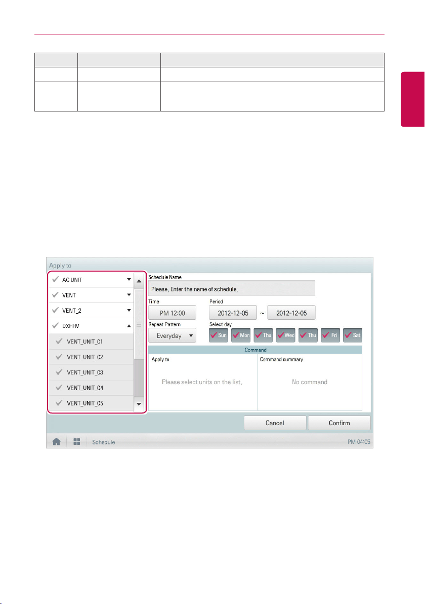
Creating Schedules
You can configure and add a schedule for a device.
1. In the main menu, click(touch) [Schedule] menu icon.
2. Click(Touch) [Add a Schedule] Button.
• The Add Schedule window opens.
3. In the group list, click(touch) a device for which a schedule is applied.
• The selected device is displayed in the applied device area of the control command
configuration.
60
ENGLISH
USING THE PROGRAM
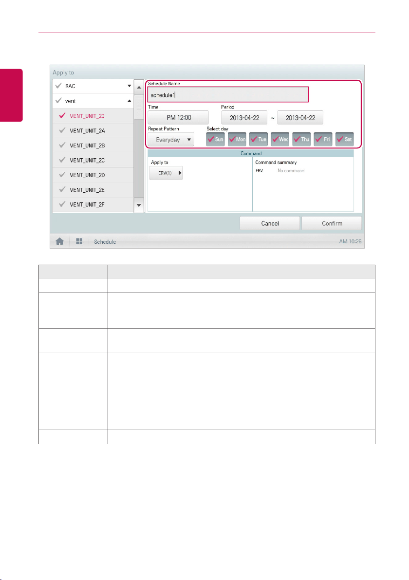
4. Configure the schedule information that controls the device.
Item Description
Schedule Name Click(Touch) the input box. Enter the name for the schedule.
Time
y Click(Touch) the time area and then the [+]/[-] button to select the desired
time.
y Click(Touch) the [AM]/[PM] button to select before or after midday.
Period
Click(Touch) the period area and then the [+]/[-] button to select the desired
period.
Repeat Program
Click(Touch) the Repetition Program area and select a desired program.
y Select Day: Selected days the schedule will be performed.
y Once: Applies a schedule once on a selected date.
y Everyday: Applies the same schedule Everyday.
y Mon - Fri: Applies a schedule repeatedly from Monday to Friday.
y Mon - Sat: Applies a schedule repeatedly from Monday to Saturday.
Select day Click(Touch) a desired day to apply a schedule.
61
ENGLISH
USING THE PROGRAM
5. Click(Touch) the device icon of the applied device.
• The control configuration window for the device is displayed. The control configuration
window differs depending on the device.
6. Configure the device control status, then click(touch) the [Confirm] button.
• The control list configured in the Command Summary area is displayed.
7. To complete the schedule configuration, click(touch) the [Confirm] button.
62
ENGLISH
USING THE PROGRAM
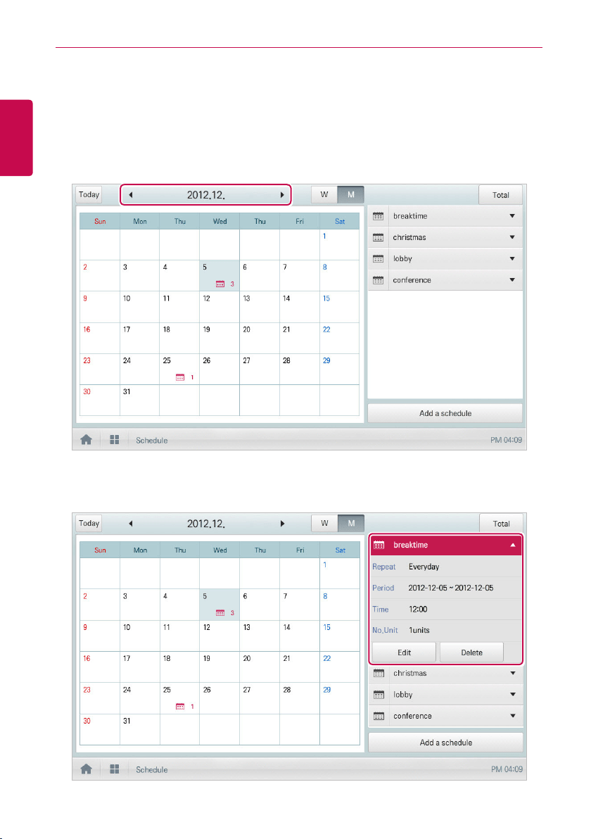
Checking Schedules
You can check registered schedules.
1. In the main menu, click(touch) the [Schedule] menu icon.
2. In the Date area, click(touch) the [◀]/[▶] button to select a schedule search period.
• The number of schedules are displayed for the selected date.
3. To check schedule details, click(touch) a schedule you want to check in the schedule list.
• Schedule details are displayed.
63
ENGLISH
USING THE PROGRAM
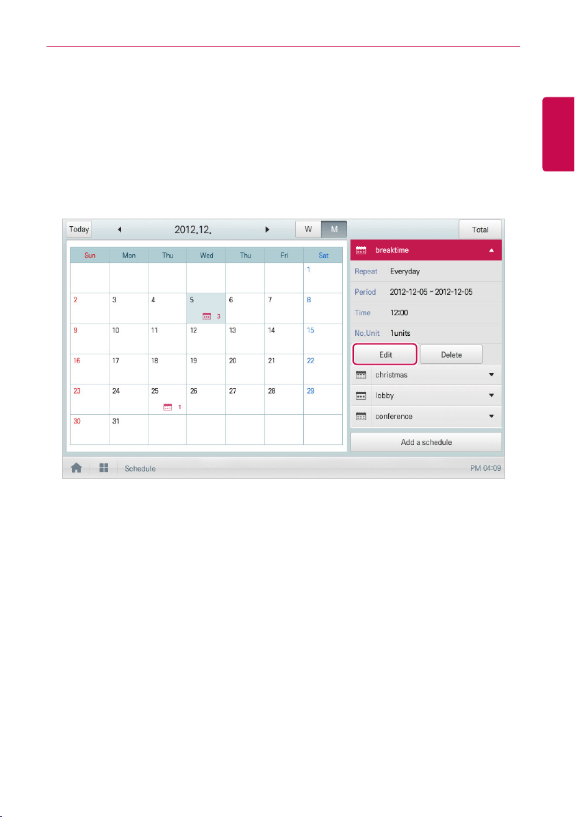
Editing Schedules
You can modify the content of a registered schedule as follows.
1. In the main menu, click(touch) the [Schedule] menu icon.
2. Click(Touch) a schedule you wish to modify from the schedule list.
• Schedule details are displayed.
3. Click(Touch) the [Edit] button.
• The schedule configuration screen is displayed.
4. Modify the schedule information and device control configuration, then click(touch) the [Confirm]
button.
• The changed data will be saved.
64
ENGLISH
USING THE PROGRAM
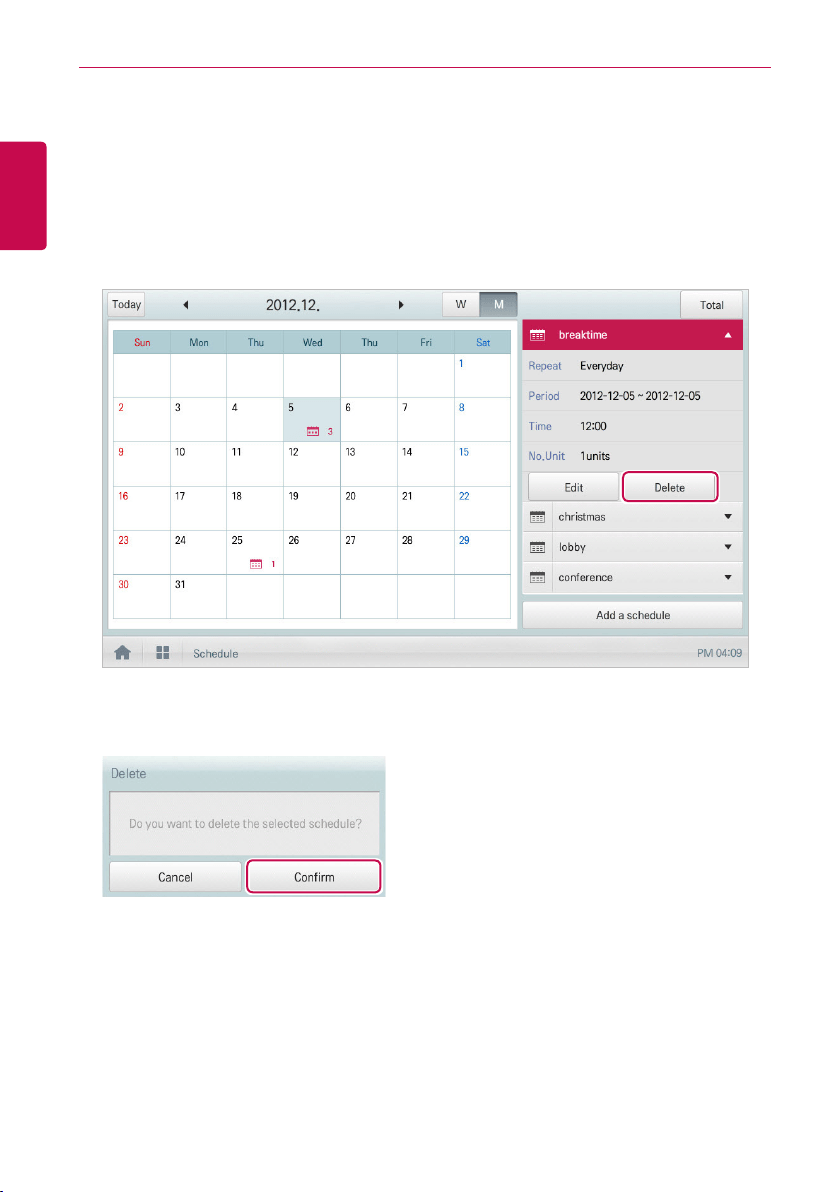
Deleting Schedules
You can delete a registered schedule as follows.
1. In the main menu, click(touch) the [Schedule] menu icon.
2. Click(Touch) a schedule you wish to delete from the schedule list.
• Schedule details are displayed.
3. Click(Touch) the [Delete] button.
4. When you are prompted to confirm the deletion, click(touch) the [Confirm] button.
• The selected schedule is deleted.

65
ENGLISH
USING THE PROGRAM
Auto Logic
Auto Logic allows the system to automatically control the power consumption of external devices.
You can also set the indoor temperature to automatically adjust to selected variables or activate
devices for certain periods of time.
NOTES
If you set a device control value in the auto logic status view, the device can operate based on
that value.
Peak Control
Peak control limits peak power consumption. You can set the target operating rate so that total
power consumption does not exceed the set limit. To prevent power consumption from exceeding the
limit, the system will switch automatically between cooling and fan modes. Also it will limit heating
operation by switching automatically between Heat and OFF modes.
NOTES
Depending on the installation site specifications, either the peak control or demand control
functions can be selected. Go to
Environment
>
Advance Setting
>
Peak/Demand Set
and
select a desired control type.
66
ENGLISH
USING THE PROGRAM
Editing Groups
The auto logic designates the registered devices as a group and controls them by group. The
following explains how to create groups and how to edit the created groups.
Adding Groups
You can create a group as follows.
1. In the main menu, click(touch) the [AutoLogic > Peak Control] menu icons.
2. Click(Touch) the [Edit Group] button.
• The screen converts to Edit Group.
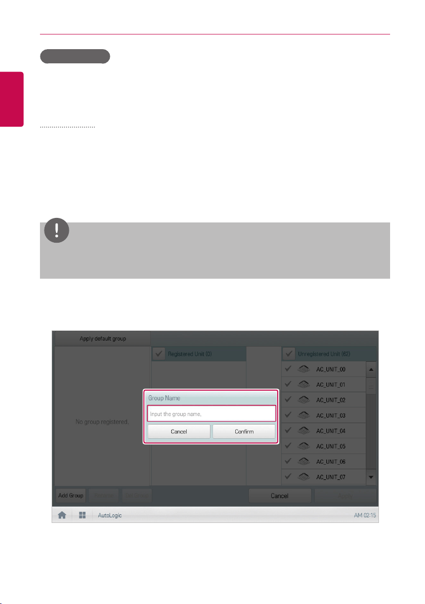
3. Click(Touch) the [Add Group] button.
NOTES
By click(touch)ing
[Apply default group]
, you can create a group automatically based on the
group and indoor unit configuration set in the Device Management menu.
4. When the window to input a group name is displayed, enter a group name and click(touch) the
[Confirm] button.
• The group is added to the group list.
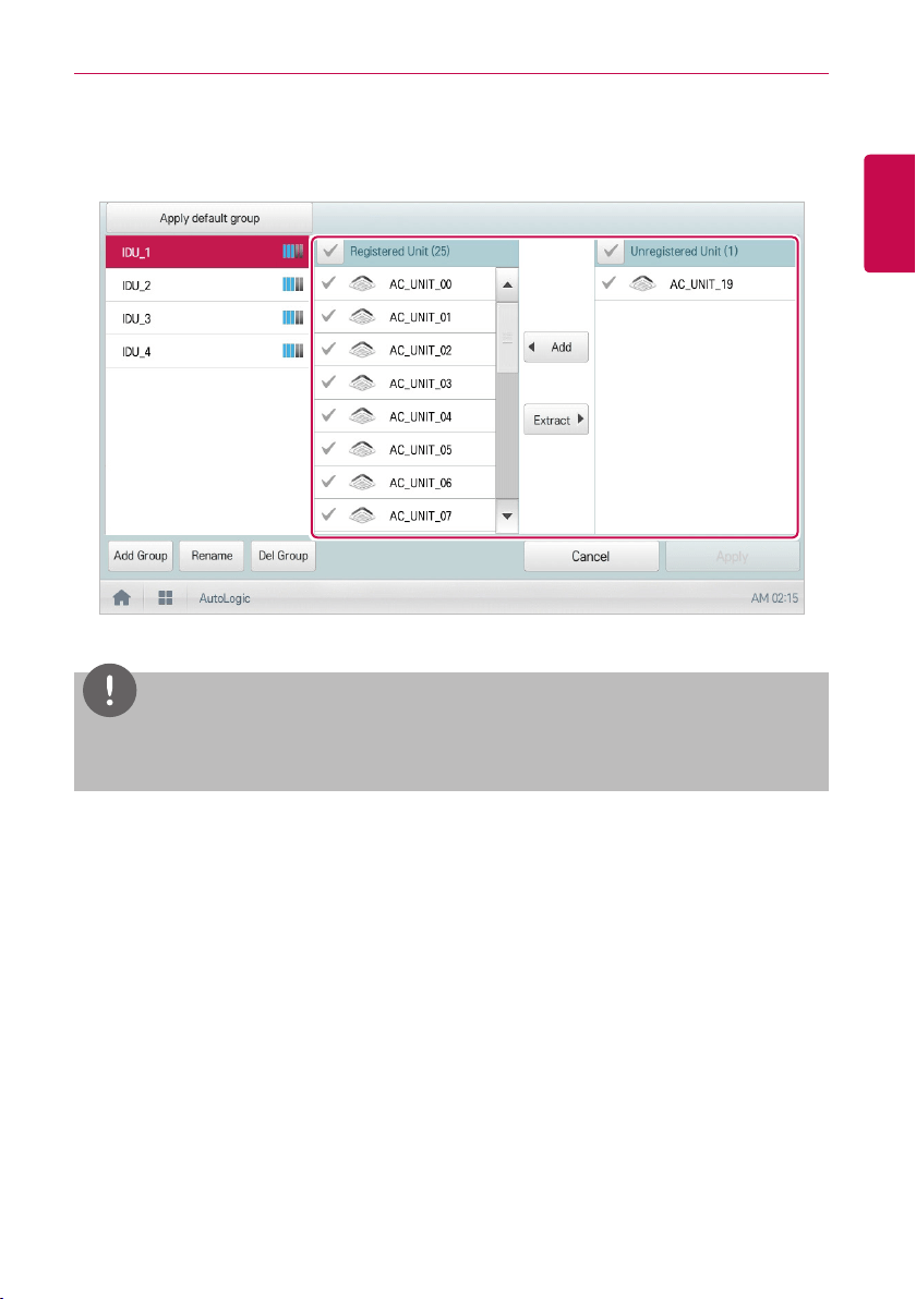
5. In the group list, click(touch) the group added in Step 4.
67
ENGLISH
USING THE PROGRAM
6. In the non-registered device area, click(touch) a device to add to the new group and click(touch)
the [Add] button.
• The selected device is moved to the registered device area.
NOTES
Peak control is only limited to indoor devices, therefore you cannot register other devices such
as the ERV, AHU or AWHP.
7. To complete group creation, click(touch) the [Apply] button.
• When all devices in the non-registered device list are registered, [Apply] button is activated.
68
ENGLISH
USING THE PROGRAM
Changing Group Name
You can change the name of a registered group as follows.
1. In the main menu, click(touch) the [AutoLogic > Peak Control] menu icon.
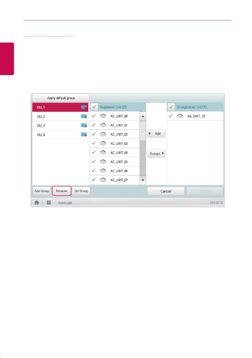
2. Click(Touch) the [Edit Group] button.
• The screen converts to Edit Group.
3. In the group list, click(touch) a group whose name you want to change and click(touch) the
[Rename] button.
4. Enter a new group name and click(touch) the [Confirm] button.
• The group name is now changed.
5. To complete group rename, click(touch) the [Apply] button.
69
ENGLISH
USING THE PROGRAM
Deleting Groups
You can delete a registered group.
1. In the main menu, click(touch) the [AutoLogic > Peak Control] menu icon.
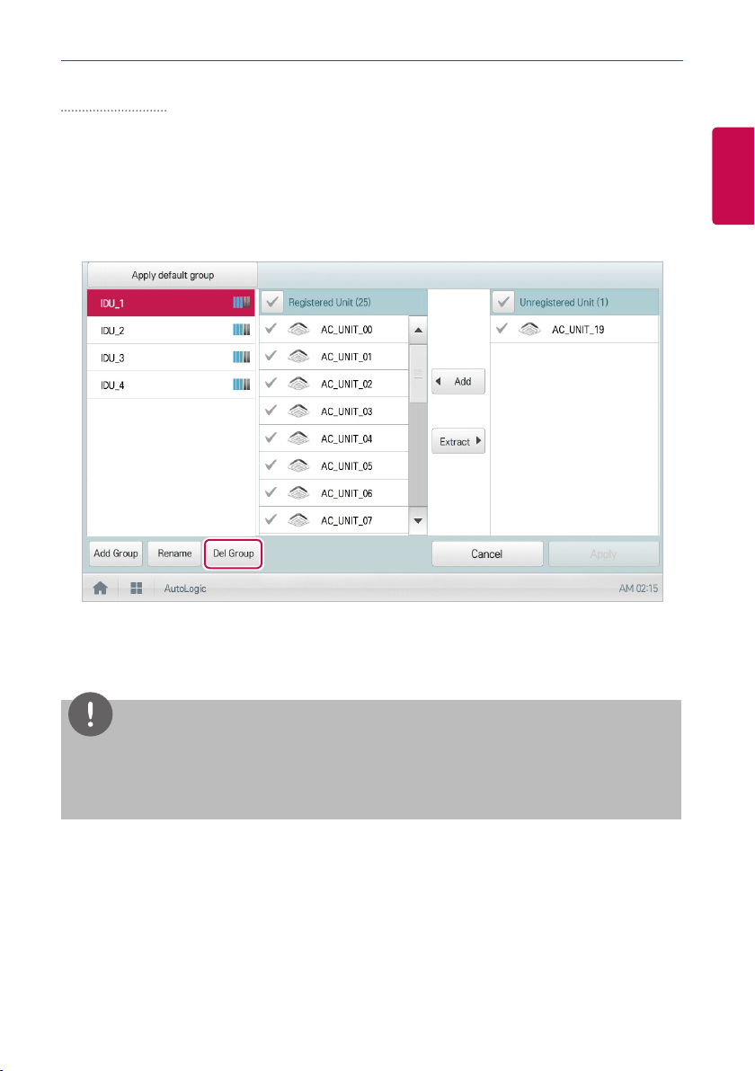
2. Click(Touch) the [Edit Group] button.
• The screen converts to Edit Group.
3. In the group list, click(touch) a group to be deleted and click(touch) the [Del Group] button.
4. When you are prompted to confirm the deletion, click(touch) the [Confirm] button.
• The selected group is deleted and the tab removed.
NOTES
y
The group configured in Peak Control is also applied to Demand Control.
y
If you change the group configuration in the device management menu, the group configured
in Peak Control is initialized.
70
ENGLISH
USING THE PROGRAM
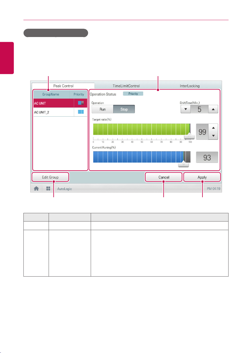
Configuring Peak Control
You can configure Peak Control as follows.
1. In the main menu, click(touch) the [AutoLogic > Peak Control] menu icon.
2. Select the control status in the control configuration area.
① ②
③ ④ ⑤
Number Item Description
①
Group List Displays the device group list and group priority.
②
Control
Configuration
Area
Configures Peak Control configuration and details.
y Operation Status
- Can be configured in [Environment > Advance Setting].
- Priority Control: Control based on group priority
- Outdoor Unit Control: Controls based on outdoor unit
capacity limit.
71
ENGLISH
USING THE PROGRAM
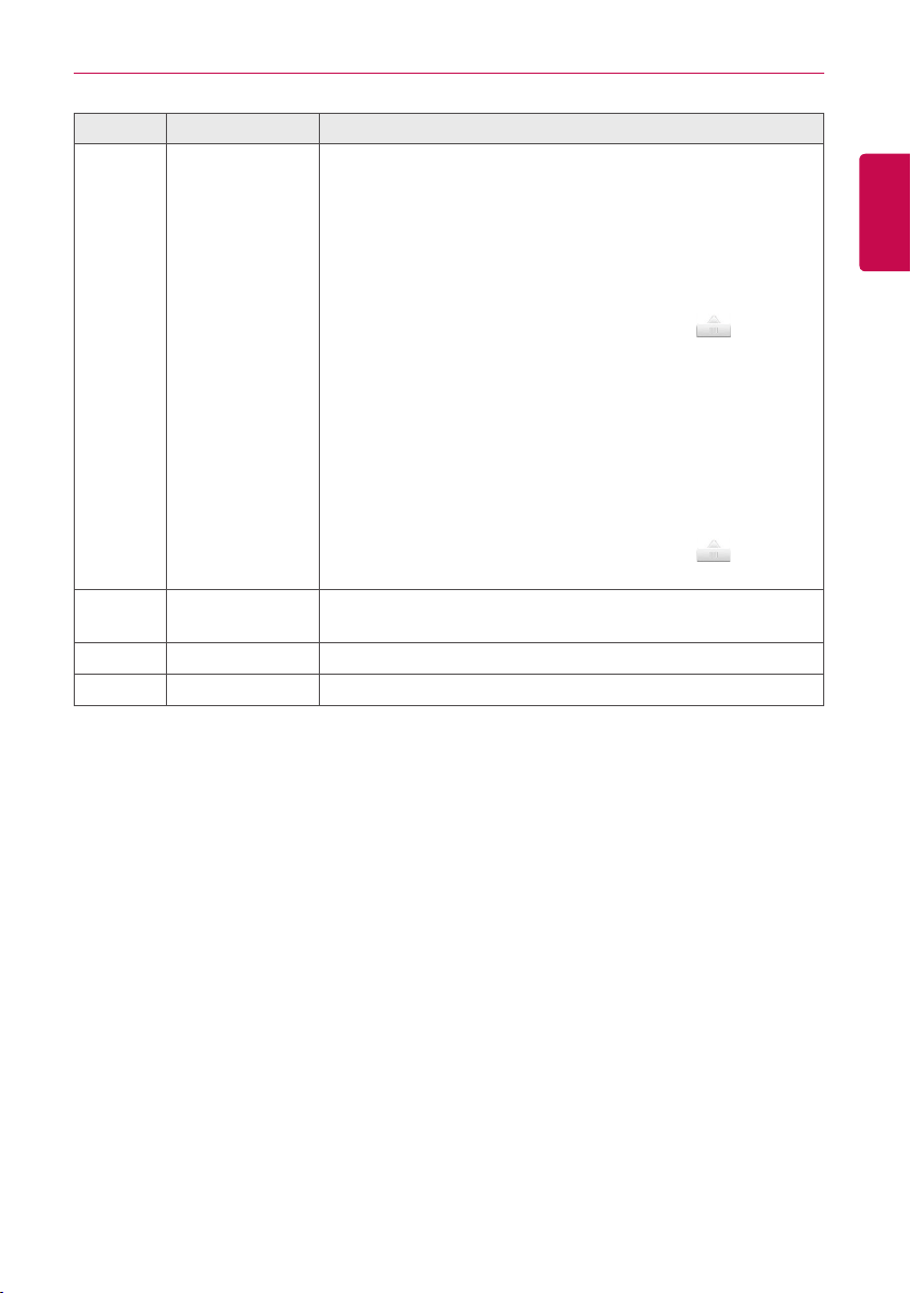
Number Item Description
②
Control
Configuration
Area
(Operation Status - Priority Control selected)
y Operation
- [Run] Button: Operates the device.
- [Stop] Button: Stops the operation of the device.
y Shift Time(Min.): Click(Touch) [▲] /[▼] to set the time in
minutes to force the operation to switch over.
y Target ratio(%): Click(Touch) [▲]/[▼] or drag button to
set the target rate.
y Current Running(%): Displays the current rate.
(Operation Status - Outdoor unit capacity control selected)
y Operation
- [Run] Button: Operates the device.
- [Stop] Button: Stops the operation of the device.
y Target ratio(%): Click(Touch) [▲]/[▼] or drag button to
set the target rate.
③
[Edit Group]
Button
Edit a control group.
④
[Cancel] Button Cancels control configuration.
⑤
[Apply] Button Applies control configuration.
3. To complete configuration, click(touch) the [Apply] button.
72
ENGLISH
USING THE PROGRAM
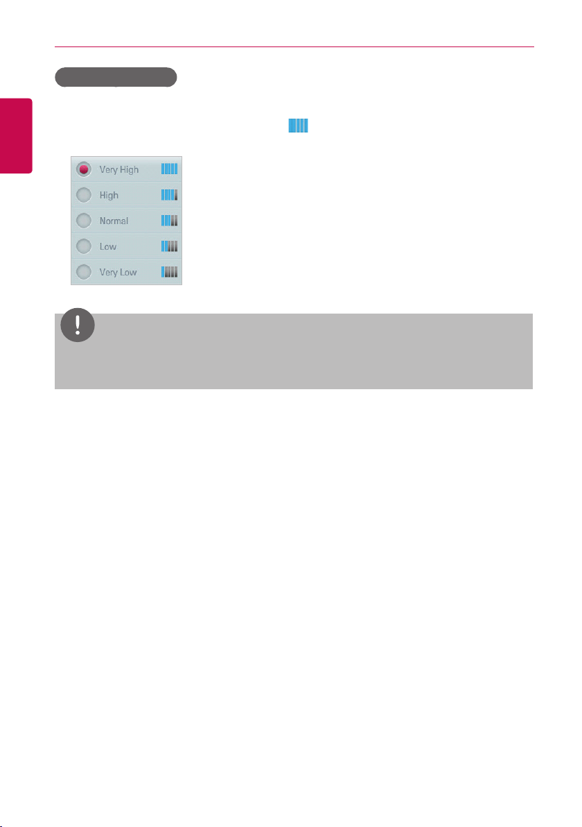
Configuring Priority
1. In the main menu, click(touch) the [AutoLogic > Peak Control] menu icon.
2. In the group list, click(touch) the priority icon ( ) of the group in question and then select a
desired priority.
NOTES
Basically, a newly added group has the highest priority. If a group is added, re-configure the
priority for all groups.
73
ENGLISH
USING THE PROGRAM
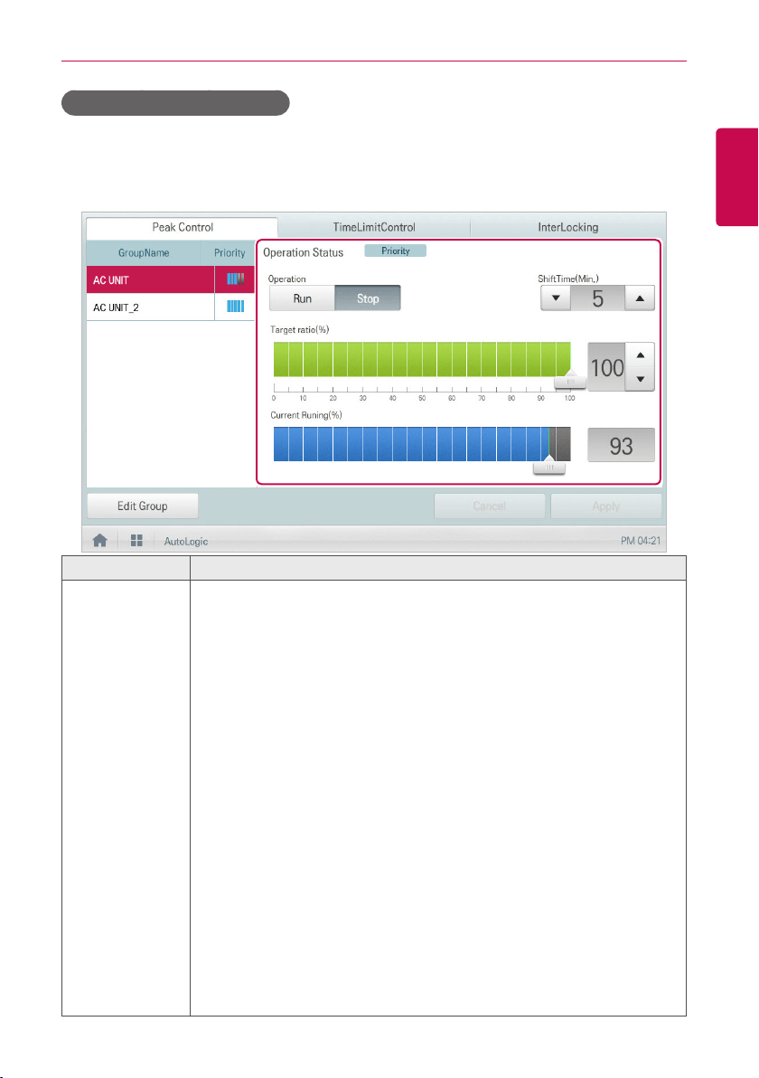
Checking Peak Control Status
You can check the Peak Control configuration status as follows.
1. In the main menu, click(touch) the [AutoLogic > Peak Control] menu icon.
2. Check how Peak Control is configured.
Item Description
Control
Configuration
Area
Configure Peak Controls.
y Operation Status
- Can be configured in [Environment > Advance Setting].
- Priority: Controls based on group priority
- Outdoor unit capacity control: Controls based on outdoor unit capacity
limit.
(Operation Status - Priority Control selected)
y Operation
- [Run] Button: Operates the device.
- [Stop] Button: Stops the operation of the device.
y ShiftTime(Min.): The cycle by which the operation switches over.
y Target ratio(%): Displays the target operation rate.
y Current Running(%): Displays the current rate.
(Operation Status - Outdoor unit capacity control selected)
y Operation
- [Run] Button: Operates the device.
- [Stop] Button: Stops the operation of the device.
y Target ratio(%): Displays the target operation rate.

74
ENGLISH
USING THE PROGRAM
Demand Control
After observing changes in power consumption, this feature can prevent power consumption from
exceeding a set limit. If you set the demand control and the program predicts that power consumption
will exceed that limit, it will begin deactivating less important devices to save energy.
NOTES
y
For demand, depending on the installation site specifications, either the peak control or
demand control functions can be selected. Go To
Environment
>
Advance Setting
>
Peak/
Demand Settings
and select a desired control type.
y
For outdoor capacity control, depending on the installation site specifications, either the peak
control or demand control functions can be selected.
y
In the Demand Control menu, you can only check the Demand Control status. You cannot
configure the operation
,
operation switchover cycle
,
desired rate
,
current rate
, etc.
NOTES
y
ACS IV Controller can be used with the LG demand controllers (PCP-D11A2J), but not with the
demand controllers from other manufacturers.
y
LG demand controller is not available in the US Market at this time.
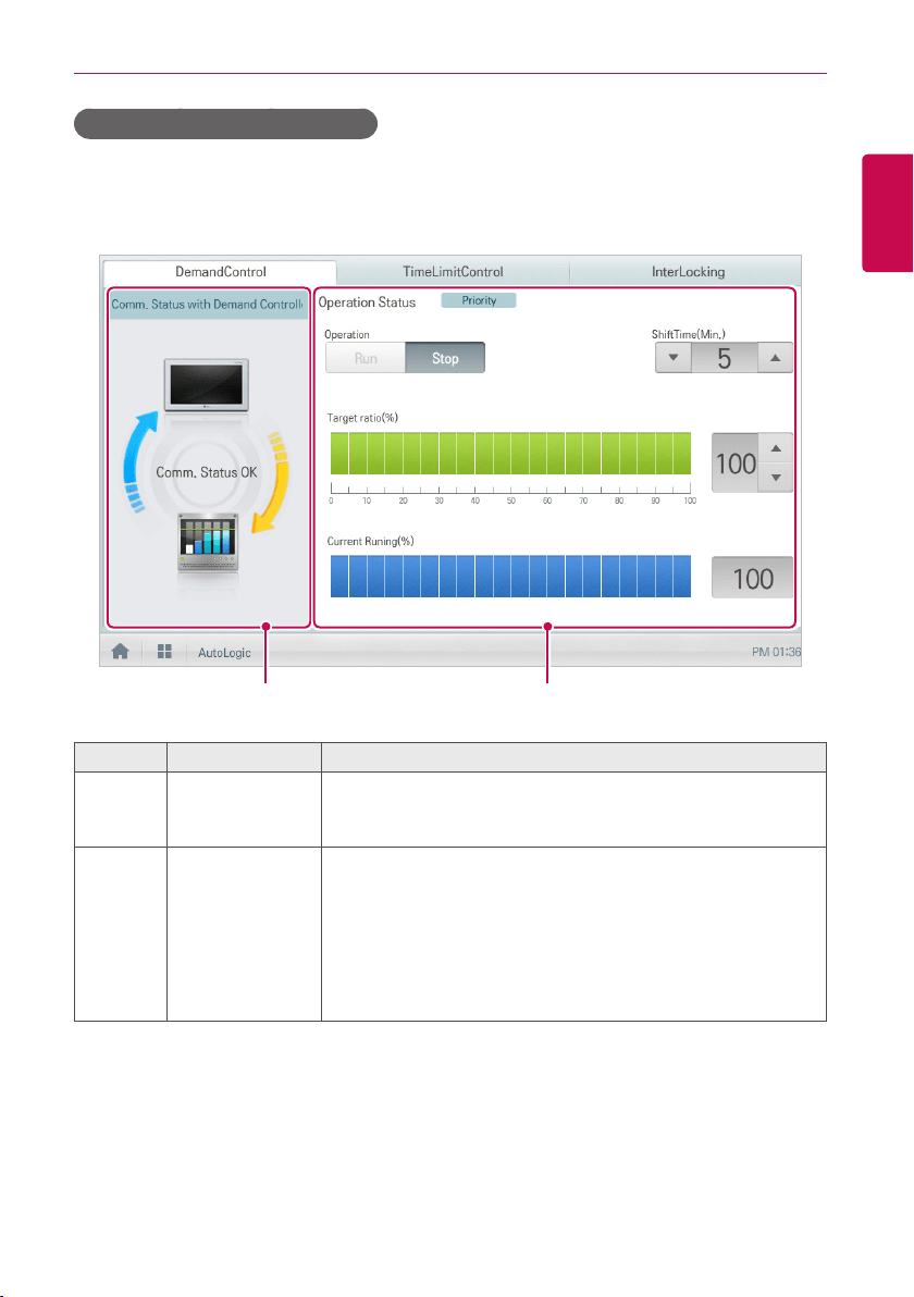
75
ENGLISH
USING THE PROGRAM
Checking Demand Control Status
You can check the Peak Control configuration status as follows.
1. In the main menu, click(touch) the [AutoLogic > Demand Control] menu icon.
2. Check how Demand Control is configured.
① ②
Number Item Description
①
Comm. Status
with Demand
Controller
Displays the communication status between demand controller
and ACS IV Controller.
②
Control
Configuration
Area
Checks the demand configuration details.
y Operation Status
- Can be configured in [Environment > Advance Setting].
- Priority Control: Control based on group priority
- Outdoor Unit Control: Controls based on outdoor unit
capacity limit.

76
ENGLISH
USING THE PROGRAM
Number Item Description
②
Control
Configuration
Area
(Operation Status - Priority Control selected)
y Operation
- [Operate] Button: Operates the device.
- [Stop] Button: Stops the operation of the device.
y Shift Time(Min.): The cycle by which the operation switches
over.
y Target ratio(%): Displays the target operation rate.
y Current Running(%): Displays the current rate.
(Operation Status - Outdoor unit capacity control selected)
y Operation
- [Run] Button: Operates the device.
- [Stop] Button: Stops the operation of the device.
y Target ratio(%): Displays the target operation rate.
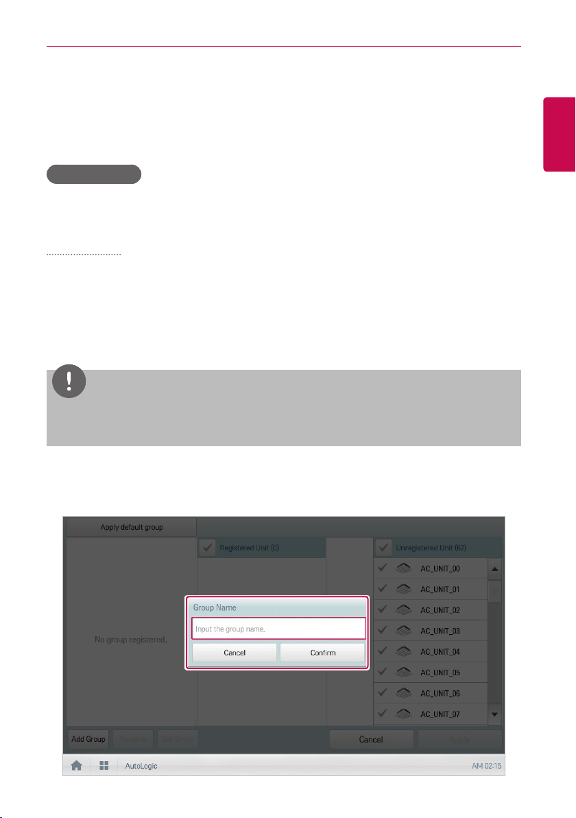
77
ENGLISH
USING THE PROGRAM
Time-limit Operation
The time-limit operation is to limit the amount of time the devices (indoor unit, ERV, DOKIT, AWHP,
and some AHU) are running individually. By setting the device operation time in advance, you can
control for how long a device works and have it stop automatically.
Editing Groups
The auto logic designates the registered devices as a group and controls them by group. The
following explains how to create groups and how to edit the created groups.
Adding Groups
You can create a group as follows.
1. In the main menu, click(touch) the [AutoLogic > TimeLimitControl] menu icon.
2. Click(Touch) the [Edit Group] button.
• The screen converts to Edit Group.
3. Click(Touch) the [Add Group] button.
NOTES
By click(touch)ing
[Apply default group]
, you can create a group automatically based on the
group
and indoor unit configuration set in the Device Management menu.
4. When the window to input a group name is displayed, enter a group name and click(touch) the
[Confirm] button.
• The group is added to the group list.
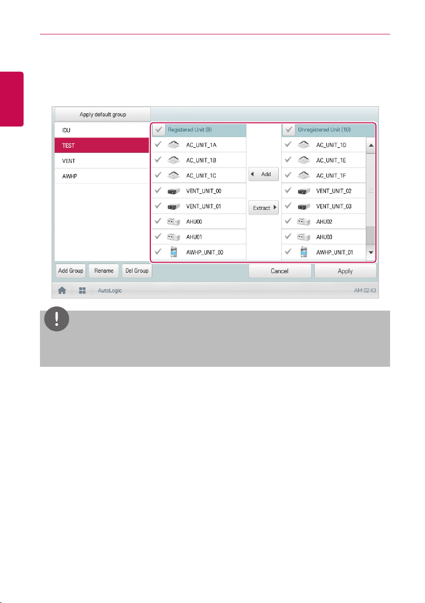
78
ENGLISH
USING THE PROGRAM
5. In the group list, click(touch) the group added in Step 4.
6. In the non-registered device area, click(touch) a device to add to the new group and click(touch)
[Add] button.
• The selected device is moved to the registered device area.
NOTES
For the time-limit operation, you cannot register chiller, AHU(Modular Fresh Air, Modular Heat
Recovery, DOAS), DI/DO, Expansion I/O.
7. To complete group creation, click(touch) the [Apply] button.
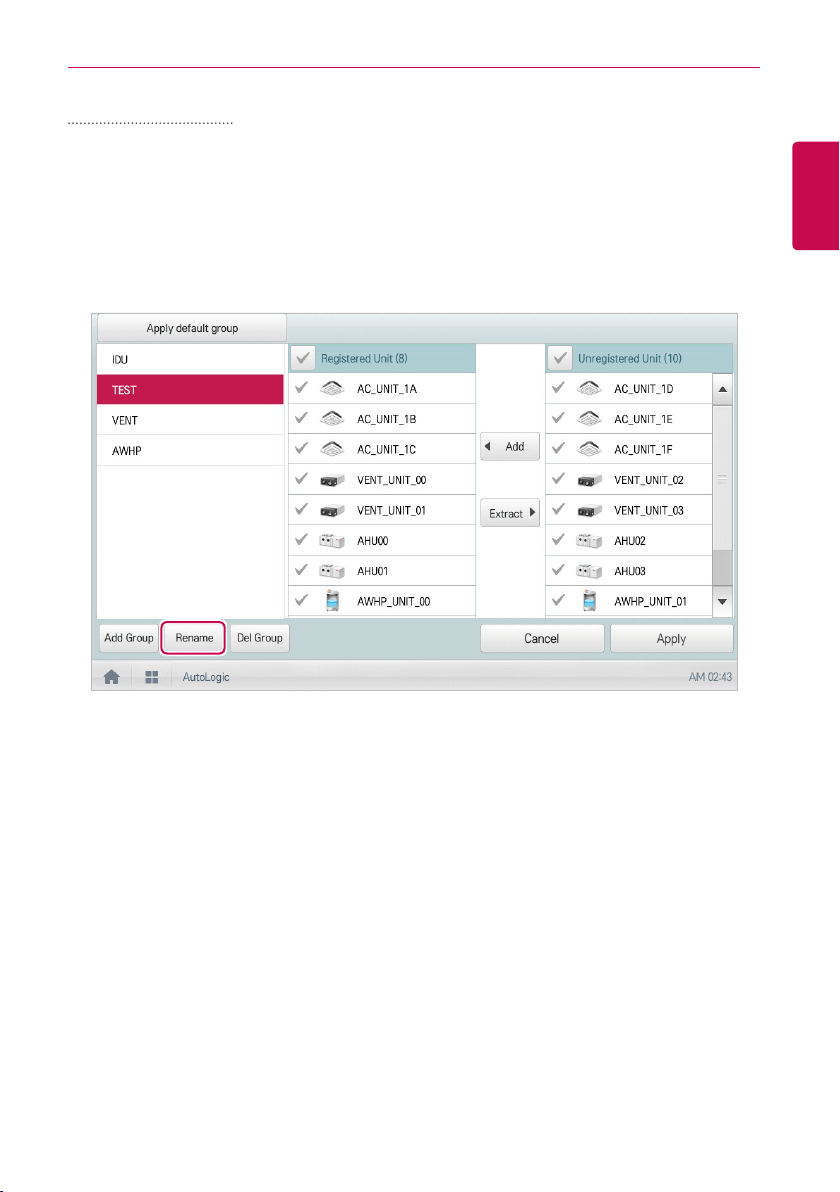
79
ENGLISH
USING THE PROGRAM
Changing Group Name
You can change the name of a registered group as follows.
1. In the main menu, click(touch) the [AutoLogic > TimeLimitControl] menu icon.
2. Click(Touch) the [Edit Group] button.
• The screen converts to Edit Group.
3. In the group list, click(touch) a group whose name you want to change and click(touch) the
[Rename] button.
4. Enter a new group name and click(touch) the [Confirm] button.
• The group name is now changed.
5. To complete group rename, click(touch) the [Apply] button.
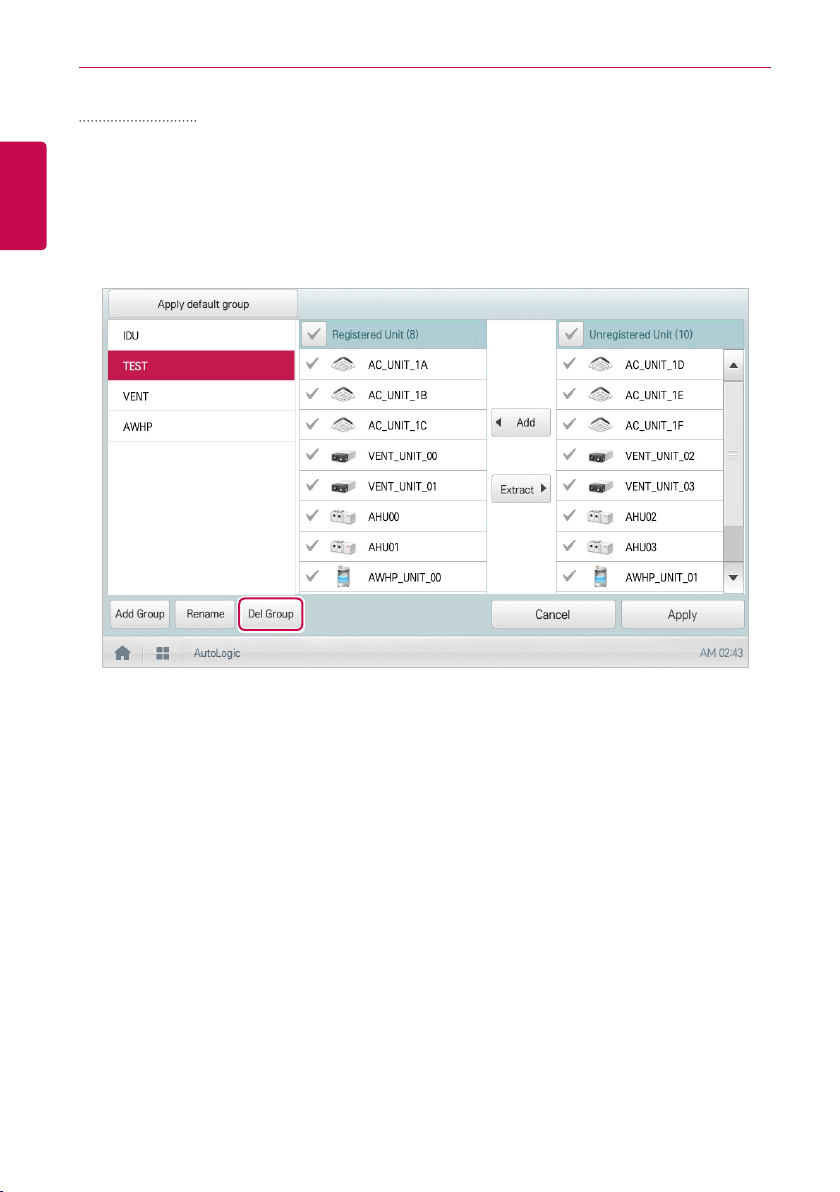
80
ENGLISH
USING THE PROGRAM
Deleting Groups
You can delete a registered group.
1. In the main menu, click(touch) the [AutoLogic > TimeLimitControl] menu icon.
2. Click(Touch) the [Edit Group] button.
• The screen converts to Edit Group.
3. In the group list, click(touch) a group to be deleted and click(touch) the [Del Group] button.
4. When you are prompted to confirm the deletion, click(touch) the [Confirm] button.
• The selected group is deleted and the tab removed.
5. To complete group delete, click(touch) the [Apply] button.
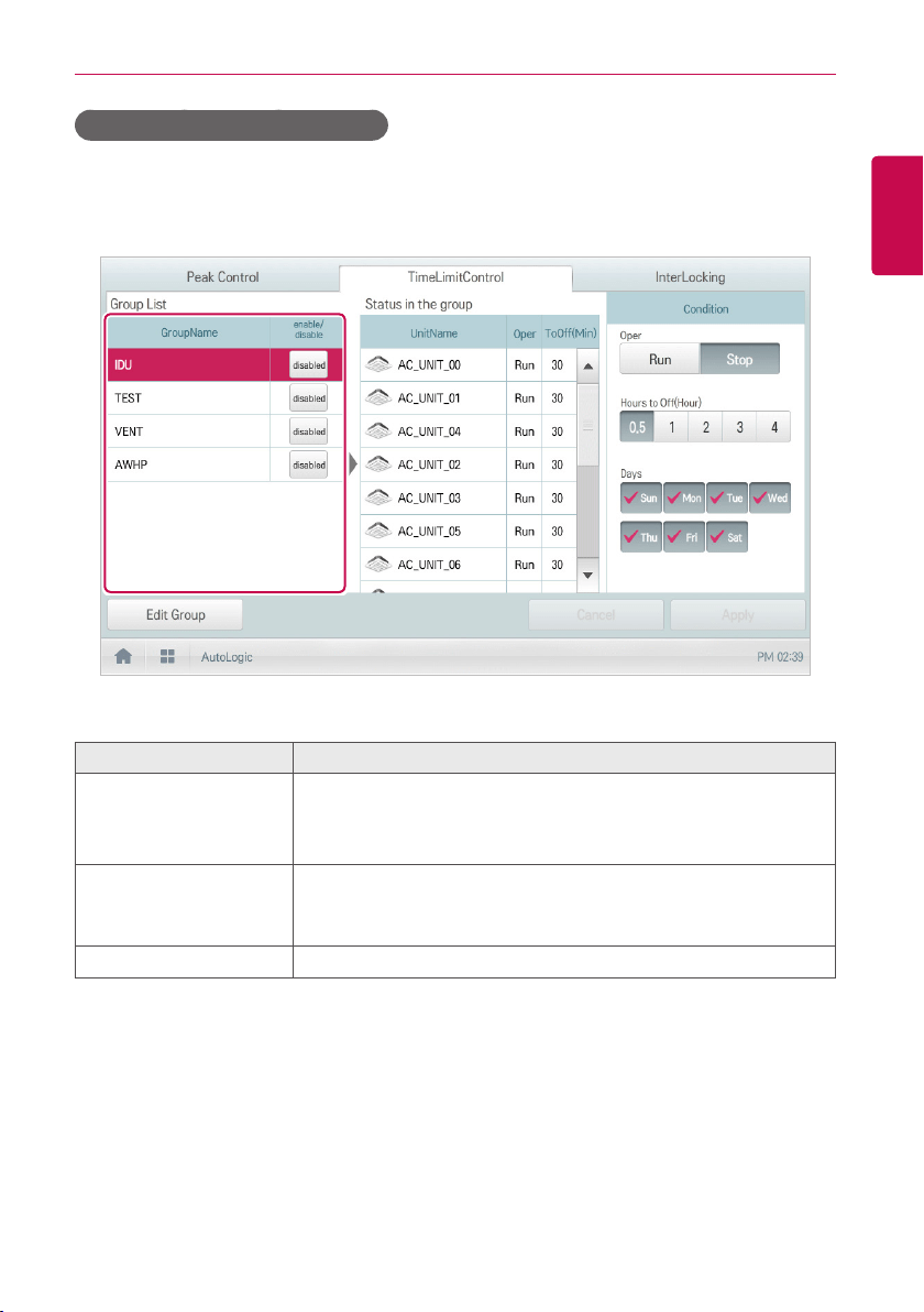
81
ENGLISH
USING THE PROGRAM
Configuring Time-Limit Operation
1. In the main menu, click(touch) the [AutoLogic > TimeLimitControl] menu icon.
2. In the group configuration status area, click(touch) a group to be controlled.
• The device list, status information, and condition details of the group are displayed.
3. Select the control status in the conditions configuration area.
Item Description
Oper
Choosing whether to run Time-Limit Operation
y [Run] Button: Run the time-limit operation.
y [Stop] Button: Stops the time-limit operation.
Hours to Off(Hour)
y Select the operation time limit of an operation group.
y The devices included in the group operate for the selected time
then stop automatically.
Days Select which day(s) of the week to run the time-limit operation.
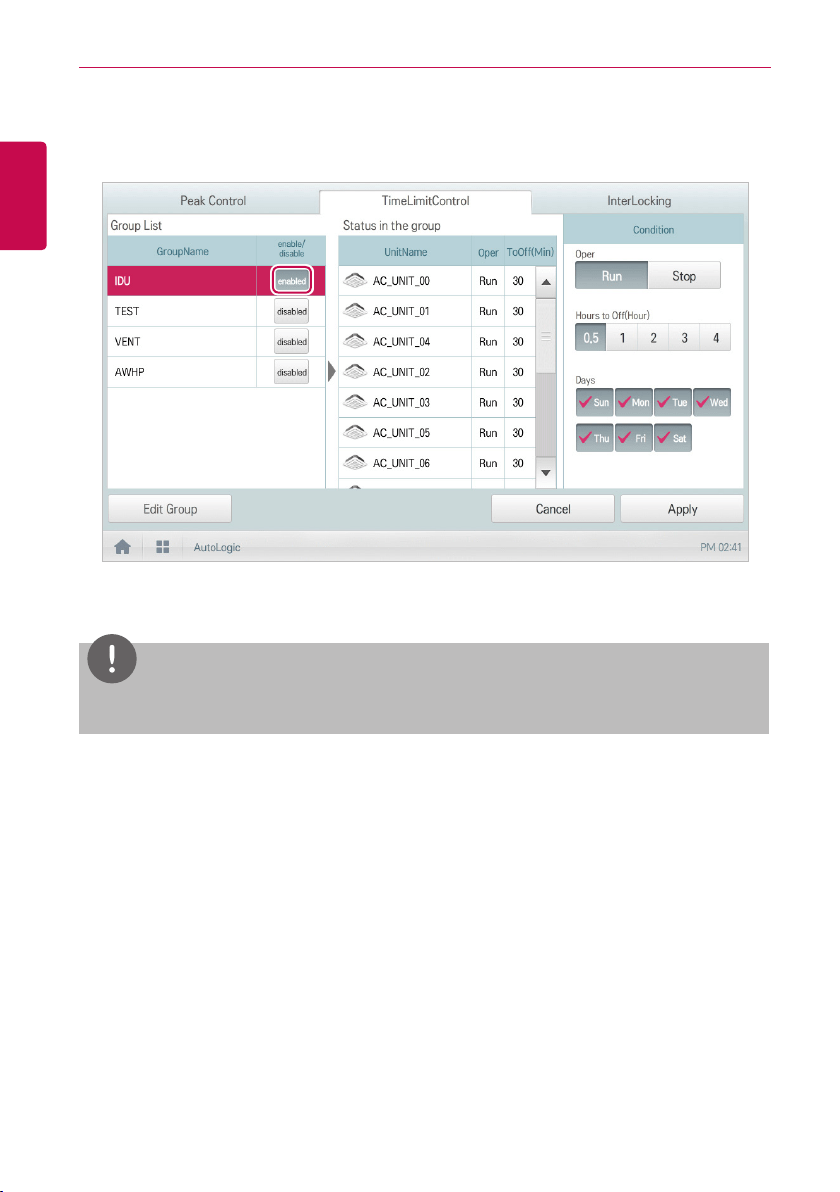
82
ENGLISH
USING THE PROGRAM
4. To run the time-limit operation on the group, in the group configuration operation status area,
click(touch) the [disable] button.
• The button changes to [enable].
5. To complete the configuration, click(touch) the [Apply] button.
NOTES
If you change the operation stop standby time, it takes about 15 seconds to apply it.
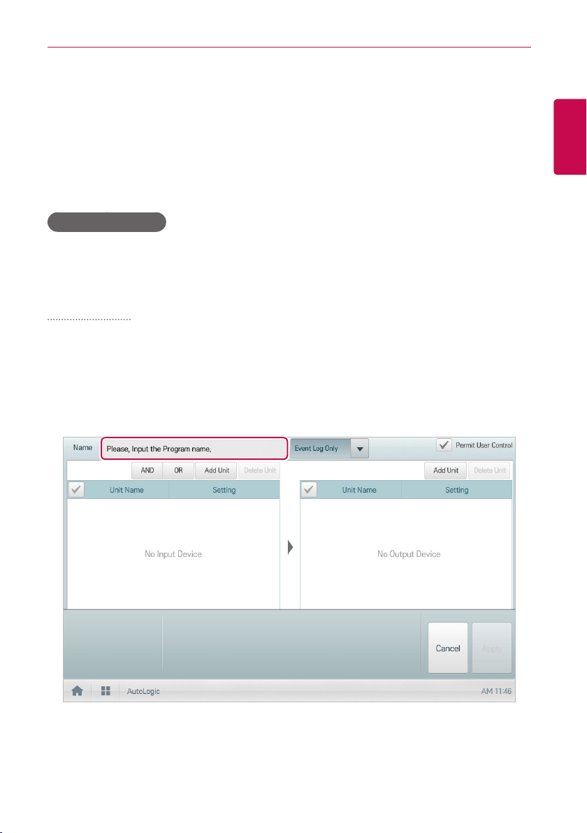
83
ENGLISH
USING THE PROGRAM
InterLocking
Associated device control is a function which interlocks more than one device and then controls
output movements when the input conditions are met.
In order to operate associated device control, you shall arrange the devices to be interlocked in a
single pattern and then apply the control setting. It is described here how to create and manage a
pattern and then proceed with associated device control.
Managing Program
The following explains how to register integrated devices as a program and how to modify or delete a
registered program.
Adding Program
You can add a program as follows.
1. In the main menu, click(touch) the [AutoLogic > InterLocking] menu icon.
2. Click(Touch) the [Add] button.
• A window to create a program is displayed.
3. Type a new program name in the program name input window.
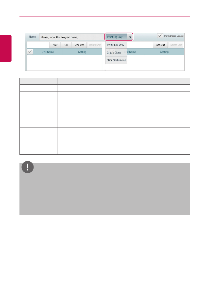
84
ENGLISH
USING THE PROGRAM
4. Select the program type.
Item Description
Event Log Only Normal device interface program
Group Clone Program to copy input setting and apply to output
Alarm ACK
Required
Device control program for emergency situation
Permit User
Control
Set priority of Interlocking. If ‘Permit User Control’ is checked, Just control
output device once when input condition is satisfied. If it is not checked,
always interlocking function takes priority.
User control
permission
Set up the priority of device linkage control. When checked, under the
status which meets the input device condition, controlling the output device
is made just once, and after that, when the user takes the control, user
control has the priority. When not checked, device linkage control always
has the priority.
NOTES
y
For device interface control, chiller and some AHU(Modular Fresh Air, Modular Heat Recovery,
DOAS) cannot be registered.
y
When it is set to emergency program, if the corresponding conditions are met, it is recognized
as emergency situation, and other control signals are blocked. For details on emergency
situation occurrences, refer to
Emergency situation occurrence and reset
.
y
You can set only 1 emergency program.
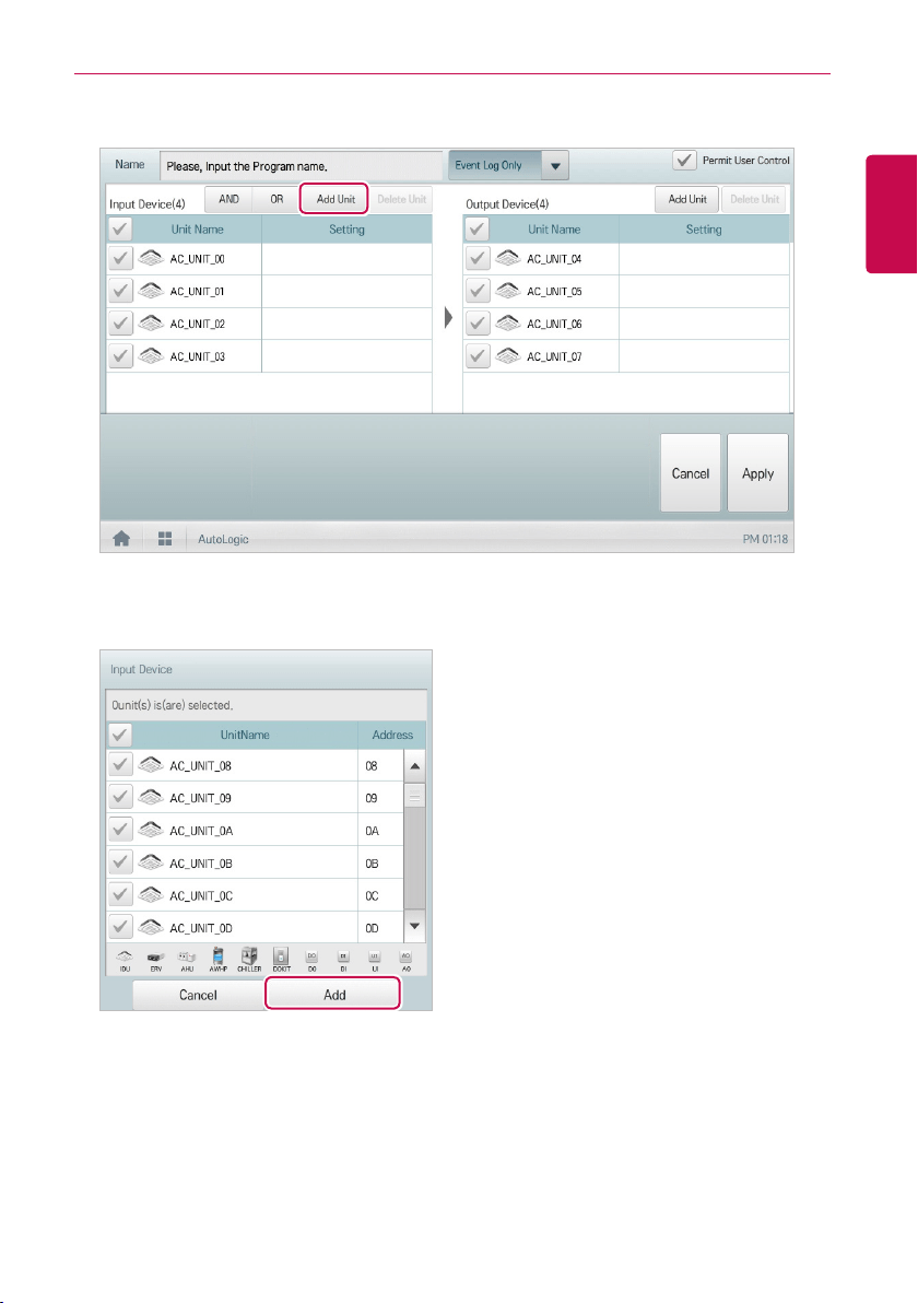
85
ENGLISH
USING THE PROGRAM
5. To register non-registered device, click(touch) the [Add Unit] button in the Input device area.
6. In the input device window, click(touch) a device to be registered and click(touch) the [Add]
button.
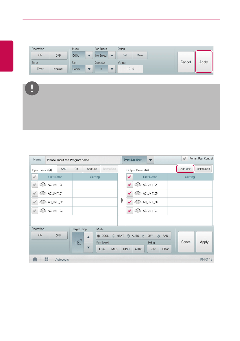
86
ENGLISH
USING THE PROGRAM
7. In the input device list, click(touch) the device you want to trigger control.
8. Select a control status in the control configuration area.
NOTES
y
Youcanusearithmeticoperators(<,≥,>,=,≤)tosetstandardvaluesofthecontrolcategory.
y
The default value of the arithmetic operator is “<”.
y
Be sure to not set the Value of input device outside the device normal operating range.
9. To register non-registered device, click(touch) the [Add Unit] button in the output device area.
10. To send the output device to register through e-mail, touch the check box of the e-mail
transmission category.
• The output device to register is sent through the set e-mail.
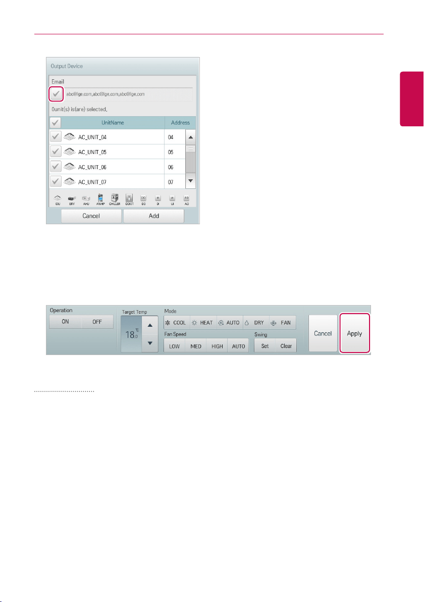
87
ENGLISH
USING THE PROGRAM
11. In the output device window, click(touch) a device to be registered and click(touch) the [Add]
button.
12. In the output device list, click(touch) the device you want to control.
13. Select a control status in the control configuration area. 16. To complete the adding of a program,
click(touch) the [Apply] button.
Editing Program
You can edit a program as follows.
1. In the main menu, click(touch) the [AutoLogic > InterLocking] menu icon.
2. Select a program and click(touch) the [Edit] button.
• The program editing screen opens.
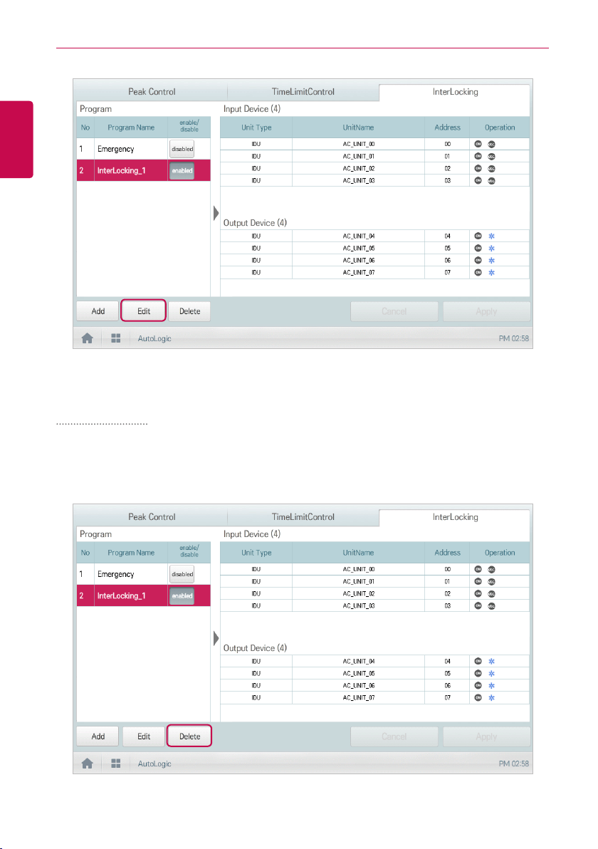
88
ENGLISH
USING THE PROGRAM
3. Modify the program configuration information and click(touch) the [Apply] button.
Deleting Program
You can delete a program as follows.
1. In the main menu, click(touch) the [AutoLogic > InterLocking] menu icon.
2. Select a program to be deleted and click(touch) the [Delete] button.
3. When you are prompted to confirm the deletion, click(touch) the [Confirm] button.
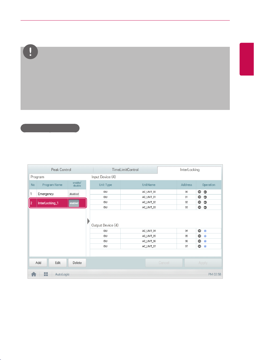
89
ENGLISH
USING THE PROGRAM
• The selected program is deleted.
NOTES
y
Be aware that there is no "undo" button for this controller.
Deleting a program is final. To restore a deleted program it would be necessary to reenter all
of the information again. (reprogram)
y
Erratic behavior will occur when an object or device is deleted from the system without first
removing the objet or device from all programs. This can occur, for example, when an auto
search is performed after any programming has been added.
Checking InterLocking
1. In the main menu, click(touch) the [AutoLogic > InterLocking] menu icon.
2. Click(Touch) a program for which you want check the device integration.
• The device integration status for the program is displayed.
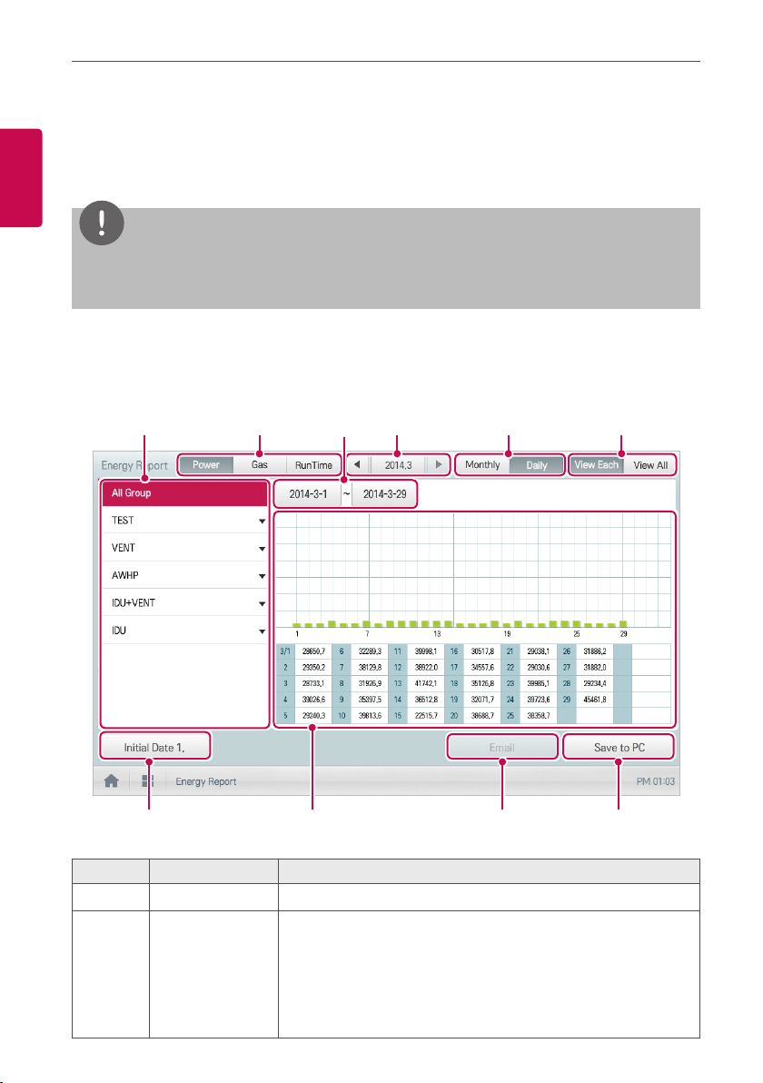
90
ENGLISH
USING THE PROGRAM
Energy Report
The following explains how to use statistics and graphs to check the power consumption, gas
consumed by LG GHP and operation time of a device.
NOTES
y
[Power]
and
[Gas]
buttons can be activated by setting each item as "use" in
[Environment >
General Setting > Power Consumption Display, Gas Consumption Display]
menu.
Statistics Screen Composition and Features
The following explains the statistics screen composition and features.
⑦
⑨
①
②
④
⑤
⑥
③
⑧
⑩
Number Item Description
①
Device List Displays the device group list or individual indoor unit list.
②
Statistics Items
y [Power] Button: You can check the power consumption of
each group and total power consumption.
y [Gas] Button: You can check the gas consumption of each
group and total gas consumption.
y [RunTime] Button: You can check the operating time and the
total operating time of indoor units in each group.

91
ENGLISH
USING THE PROGRAM
Number Item Description
③
Daily Query
Period Selection
Area
y Selects the period for which you want to query statistics
details for daily.
y The start date should be no more than 31days before the end
date.
y You can set detail period only when the inquiry unit is [Daily].
④
Monthly Query
Period Selection
Area
y Selects the period for which you want to query statistics
details for monthly.
⑤
Query Unit
y [Monthly] Button: Queries on monthly consumption within the
last four months.
y [Daily] Button: Queries on daily consumption within the query
period.
⑥
[View Each]/
[View All] Button
Switching of the energy report data viewing method
y View Each: View the selected energy report data in graph
format.
y View All: View the total energy report data in the table
format.
⑦
[Initial Date]
Button
Set energy report base date for each of power/gas/operation
hours
⑧
Displays
Energy Report
Information
y Energy report data of each period: Display power
consumption, gas consumption for each unit or operation
hours energy report value and graph
⑨
[Email] Button
In [Environment > E-Mail Setting] menu, you need to set the
e-mail usage to ON to use this function.
The queried statistics data will be sent to the Email address
registered in the Preference menu.
⑩
[Save to PC] or
[Save to USB]
button
y ACP IV: Save the statistics data to a PC.
y AC Smart IV / AC Smart BACnet(Web): Save the statistics
data to a PC.
y AC Smart IV / AC Smart BACnet(Controller): Save the
statistics data to a USB memory stick.
y ACP BACnet : Save the statistics data to a PC.
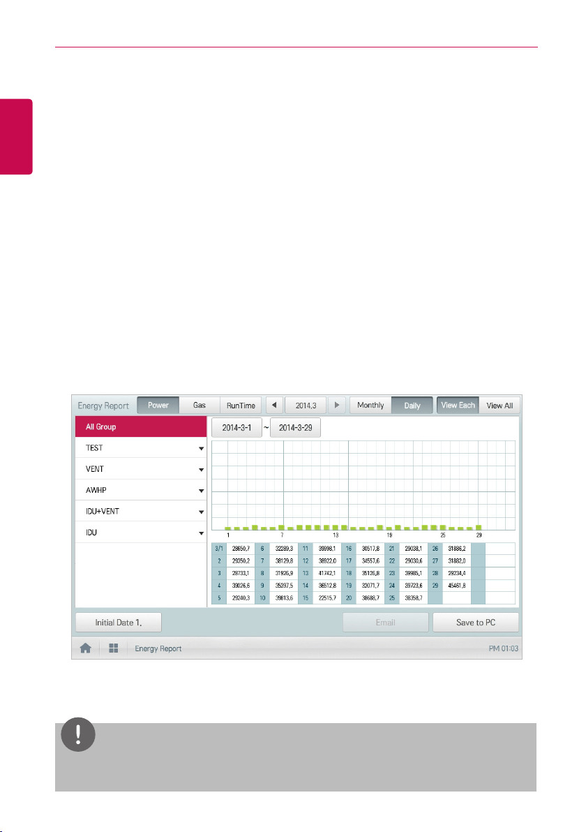
92
ENGLISH
USING THE PROGRAM
Querying Energy Report
You can query the power or gas consumption of a device or operation time statistics data as follows.
1. In the main menu, click(touch) the [Energy Report] menu icon.
2. Click(Touch) the device group you want from the group list.
3. Click(Touch) the button of the energy report item you want.
• [Power] Button: You can check the power consumption of each group and total power
consumption.
• [Gas] Button: You can check the gas consumption of each group and total gas consumption.
• [RunTime] Button: You can check the operating time and the total operating time of indoor
units in each group.
4. In the query period selection area, click(touch) the date button and [+]/[-] button to select the
desired period.
• The start date should be no more than 31days for daily before the end date. The query period
for monthly is automatically fixed to the last four months.
5. Check the energy report details in the energy report information display area.
• To change the energy report information view type, click(touch) the [View Each] or [View All]
button.
6. To send the energy report data by email, click(touch) the [Email] button. To save it to a PC or a
USB memory stick, click(touch) the [Save to PC] or [Save to USB] button.
NOTES
The energy report data is stored up to 6 months.

93
ENGLISH
USING THE PROGRAM
NOTES
y
Devices which are displayed in the Run Time: Indoor units
y
Devices which are displayed in the Power consumption: devices which can be used with the
PDI (For further information about the devices that are compatible with the PDI, please refer to
the PDI manual.)
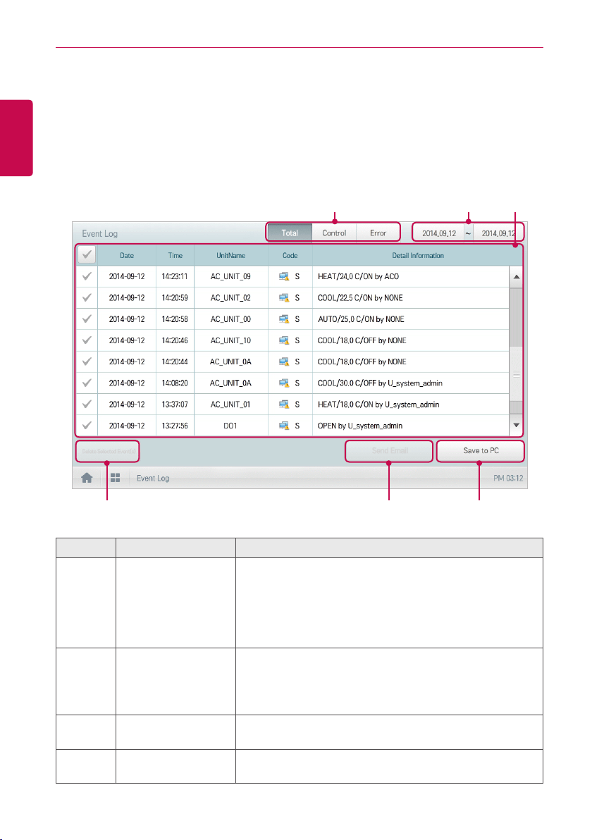
94
ENGLISH
USING THE PROGRAM
Event Log
The following explains how to query the device control information or error information.
Event log screen composition and features
The following explains the event log screen composition and features.
④ ⑤ ⑥
① ② ③
Number Item Description
①
Report Items
Selects report query items.
y [Total] Button: Queries all reports regarding control and
error.
y [Control] Button: Queries control related reports only.
y [Error] Button: Queries error related reports only.
②
Query Period
Selection Area
y Selects the period for which you want to query report
details.
y The starting date should be no more than three months
from the ending date.
③
Report detail display
area
Displays the reports related to control and error.
④
[Delete Report]
Button
Deletes the selected report.

95
ENGLISH
USING THE PROGRAM
Number Item Description
⑤
[Send Email] Button
In [Environment > E-Mail Setting] menu, you need to set
the e-mail usage to ON to use this function.
The queried reports will be sent to the Email address
registered in the Environment menu.
⑥
[Save to PC] or
[Save to USB] Button
y ACP IV: Save the reports to a PC.
y AC Smart IV / AC Smart BACnet(Web): Save the
reports to a PC.
y AC Smart IV / AC Smart BACnet(Controller): Save the
reports to a USB memory stick.
y ACP BACnet: Save the reports data to a PC.
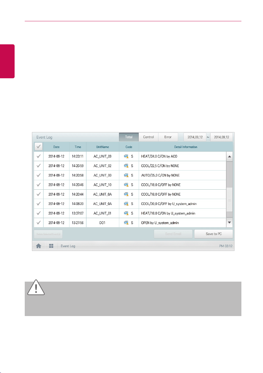
96
ENGLISH
USING THE PROGRAM
Querying Event
You can query the device control event or error event as follows.
1. In the main menu, click(touch) the [Event Log ] menu icon.
2. In the event item, click(touch) an item for which you want to query a event.
• [Total] Button: Queries all events regarding control and error.
• [Control] Button: Queries control related events only.
• [Error] Button: Queries error related events only.
3. In the query period selection area, click(touch) the date button and [+]/[-] button to select the
desired period.
• The starting date should be no more than three months from the ending date.
4. Check the event details in the event detailed information column.
5. To send the event detail by email, click(touch) the [Send Email] button. To save it to a PC or a
USB memory stick, click(touch) the [Save to PC] or [Save to USB] button.
Caution
You can query up to 200 events and email/save to PC, USB memory up to 300 events. Up to
5000 events are stored total.
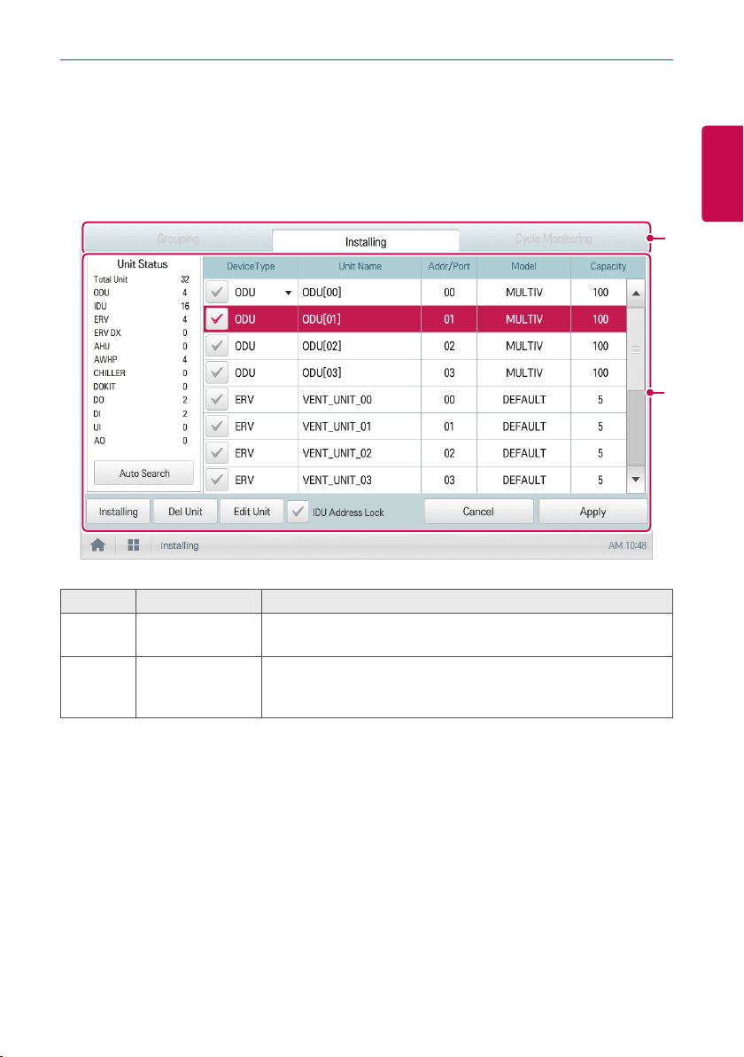
97
ENGLISH
USING THE PROGRAM
Installing
You can add a device or change the settings of a registered device.
Device setting screen composition and function
②
①
Number Item Description
①
Device setting tab
Displayed as group management/device management/view cycle
tab
②
Detail setting
Displays the details of the device setting
(Screen composition is different according to the device setting
tab type.)
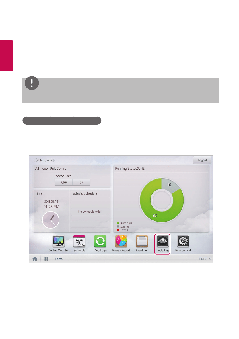
98
ENGLISH
USING THE PROGRAM
Registering Device
After installing ACS IV Controller, log into ACS IV Controller to register the devices to be connected,
using one of the following two methods.
• Registering Device Automatically
• Registering Device Manually
NOTES
To register a device on ACS IV Controller, you must login with administrator permissions.
Registering Device Automatically
Devices connected to ACS IV Controller are automatically searched for and registered. You can
register a device automatically as follows.
1. In the main menu, click(touch) the [Installing] menu icon.
2. Click(Touch) the [Installing] tab.
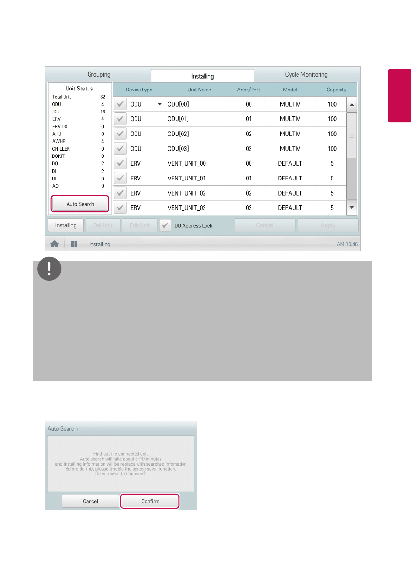
99
ENGLISH
USING THE PROGRAM
3. Click(Touch) the [Auto Search] button.
NOTES
y
Auto search requires up to 10 minutes. Before touching
[Auto search]
button, please
deactivate screen protector function. If screen protector is in operation, the screen automatically
switches to home screen and auto search operation is cancelled. For the setting on whether to
use screen protector, refer to
Setting a Screen saver
. (AC Smart IV Only)
y
Chiller, some AHU(Modular Fresh Air, Modular Heat Recovery, DOAS) and Exp.I/O does not
support auto search function. This device must be installed manually.
y
Exp.I/O is activated when
'Enable'
is checked in the device edit window after registering the
device.
4. When you are prompted to confirm the setting, click(touch) the [Confirm] button.
• It takes 5 to 10 minutes to register devices automatically.
5. To save the searched devices, click(touch) the [Apply] button.
• Device registration is completed. Local DIs and DOs are always added to the Unit Status area
as they are part of the ACS IV Controller hardware.
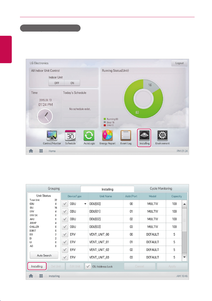
100
ENGLISH
USING THE PROGRAM
Registering Device Manually
Devices connected to ACS IV Controller can be registered by the user by entering relevant
information. You can register a device manually as follows.
1. In the main menu, click(touch) the [Installing] menu icon.
2. Click(Touch) the [Installing] tab.
3. Type the device information and click(touch) the [Installing] button.
• A window to add unit is displayed.
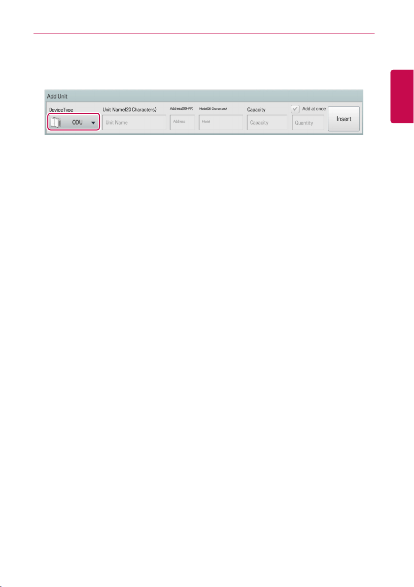
101
ENGLISH
USING THE PROGRAM
4. In the Add Unit window, select a device type to add.
• You can add outdoor unit, indoor unit, ventilation, direct type ventilation, AHU, AWHP, Chiller,
DOKIT, DO, DI, and Exp.I/O.
5. Enter the device name to add and click(touch) the [Insert] button.
• According to the selected device, the setting category is displayed differently according to the
corresponding device. For setting information of each device, refer to Setting information of
each device.
6. To save the device, click(touch) the [Apply] button.
• Device registration is completed.
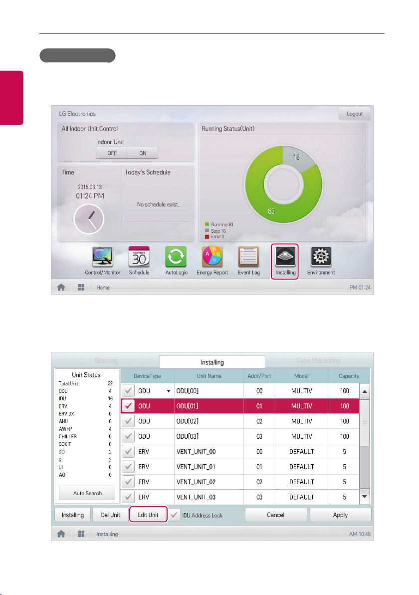
102
ENGLISH
USING THE PROGRAM
Changing Device
You can change the settings of registered devices.
1. In the main menu, click(touch) the [Installing] menu icon.
2. Click(Touch) the [Installing] tab.
3. In the device list, select the device to change, and touch [Edit Unit] button.
• Edit device window is displayed.
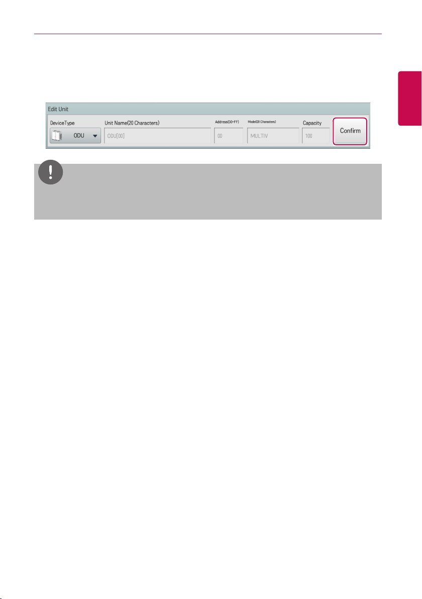
103
ENGLISH
USING THE PROGRAM
4. Input the setting information of the device to change, and touch [Confirm] button.
• According to the selected device, the setting category is displayed differently according to the
corresponding device. For setting information of each device, refer to Setting information of
each device.
NOTES
If you select several devices of the same type and click(touch) the
[Edit Unit]
button, you can
change some setting information at once.
5. To save a change, click(touch) the [Apply] button.
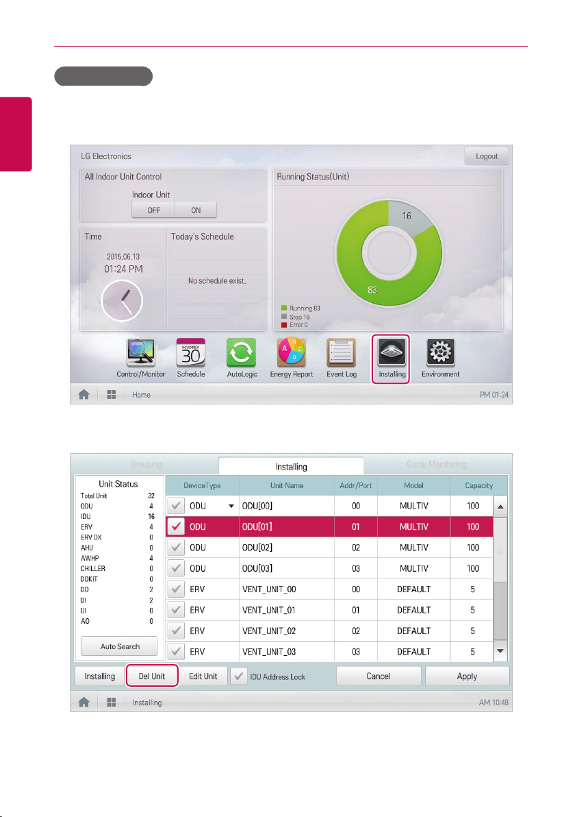
104
ENGLISH
USING THE PROGRAM
Deleting Device
Follow these steps to delete a device from the list.
1. In the main menu, click(touch) the [Installing] menu icon.
2. Click(Touch) the [Installing] tab.
3. In the device list, click(touch) a device to be deleted and click(touch) the [Del Unit] button.
4. When you are prompted to confirm the deletion, click(touch) the [Confirm] button.
• The selected device is deleted from the list.
5. To save a change, click(touch) the [Apply] button.
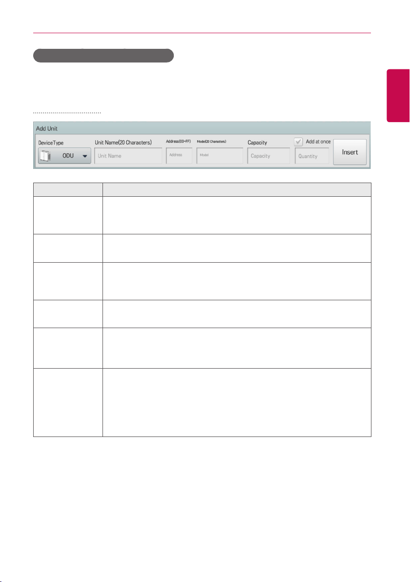
105
ENGLISH
USING THE PROGRAM
Setting information of each device
The setting information of each device is as follows.
ODU, ERV, ERV DX
Item Description
Device Type
Select a device type.
y ODU(Outdoor unit), ERV(Energy Recovery Ventilator),
ERV DX(Direct Expansion Energy Recovery Ventilator)
Unit Name
(20 Characters)
Enter the device name.
y Up to 20 characters.
Address
(00-FF)
Type the central control address of the device.
y A central control address value is a number between 00 and FF. You can
use only 1 device per address.
Model
(20 Characters)
Type the device model.
y Up to 20 characters.
Capacity
Type the maximum capacity in thousand BTUs for devices.
y Up to 5 characters.
y The capacity of the actual device cannot exceed the input value.
Add at once
y It is used when you need to add several devices of the same type.
y Select check box, input the desired number of devices, and the devices
are added at once, and the device name and address are automatically
increased.
(During the Add all, if duplicate address value occurs, the information
notice message for the duplicate address is displayed.)
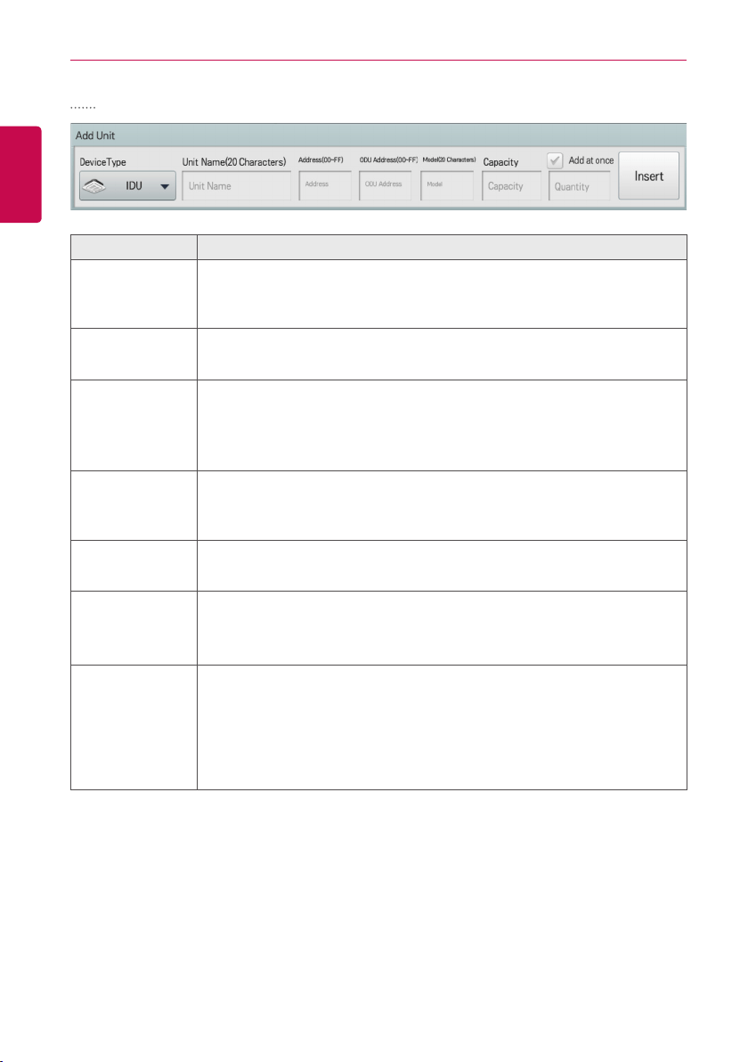
106
ENGLISH
USING THE PROGRAM
IDU
Item Description
Device Type
Select a device type.
y Cassette(4Way), Cassette(2Way), Cassette(1Way), Duct, Floor Mounted,
Wall Mounted, FCU
Unit Name
(20 Characters)
Enter the device name.
y Up to 20 characters.
Address
(00-FF)
Type the central control address of the device.
y A central control address value is a number between 00 and FF. You
cannot type the same value for similar devices.
y You cannot enter a duplicate value for indoor devices and DOKIT.
Outdoor unit
address
Input physical address of the connected outdoor unit.
y A central control address value is a number between 00 and FF. You
cannot type the same value for similar devices.
Model
(20 Characters)
Type the device model.
y Up to 20 characters.
Capacity
Type the maximum capacity in thousand BTUs for devices.
y Up to 5 characters.
y The capacity of the actual device cannot exceed the input value.
Add at once
y It is used when you need to add several devices of the same type.
y Select check box, input the desired number of devices, and the devices
are added at once, and the device name and address are automatically
increased.
(During the Add all, if duplicate address value occurs, the information
notice message for the duplicate address is displayed.)
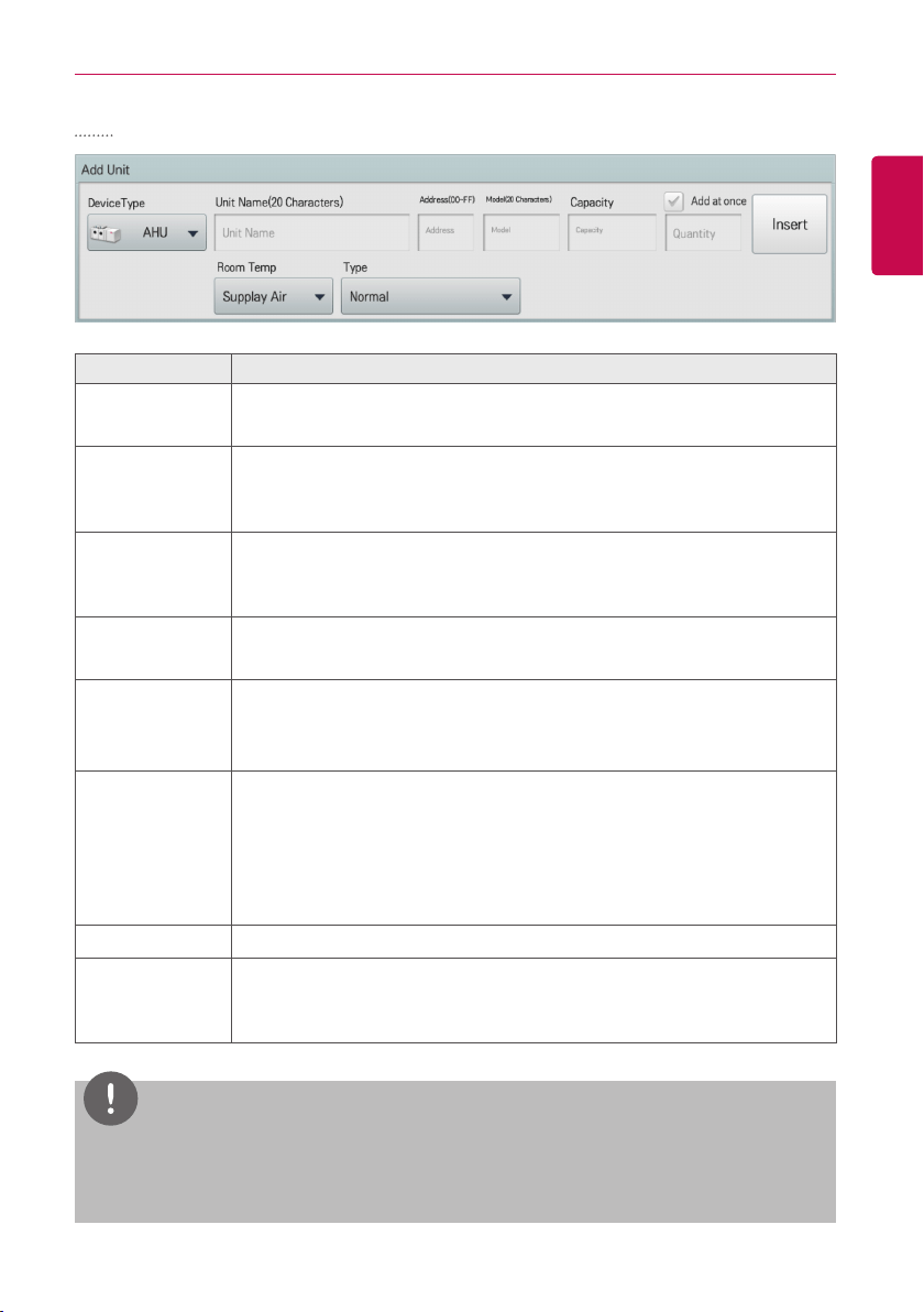
107
ENGLISH
USING THE PROGRAM
AHU
Item Description
Device Type
Select a device type.
y AHU
Unit Name
(20 Characters)
Enter the device name.
y A central control address value is a number between 00 and 1F. You
cannot type the same value for similar devices.
Address
(00-FF)
Type the central control address of the device.
y A central control address value is a number between 00 and FF. You
cannot type the same value for similar devices.
Model
(20 Characters)
Type the device model.
y Up to 20 characters.
Capacity
Type the maximum capacity in thousand BTUs for devices.
y Up to 5 characters.
y The capacity of the actual device cannot exceed the input value.
Add at once
y It is used when you need to add several devices of the same type.
y Select check box, input the desired number of devices, and the devices
are added at once, and the device name and address are automatically
increased.
(During the Add all, if duplicate address value occurs, the information
notice message for the duplicate address is displayed.)
Room Temp Select indoor temperature setting base(air supply/ventilation).
Type
Select a AHU type.
y Normal, Fresh Air, Heat Recovery, Modular Fresh Air, Modular Heat
Recovery, DOAS.
NOTES
y
Address of the products linked to the MODBUS communication system recommend a number
between 01~F7.
y
DOAS fixes the room temperature setup standard as "air supply".
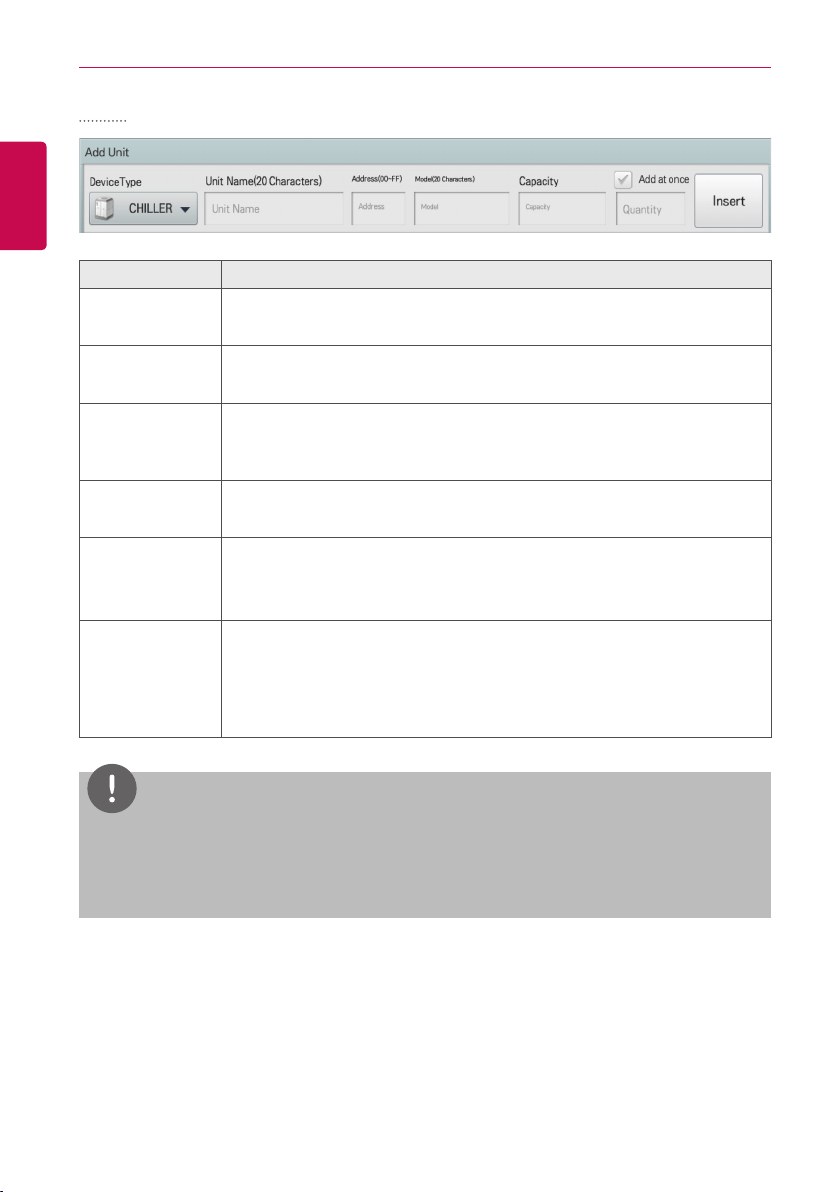
108
ENGLISH
USING THE PROGRAM
Chiller
Item Description
Device Type
Select a device type.
y Water-cooled scroll/Air-cooled scroll/Turbo/Screw/ABS chiller
Unit Name
(20 Characters)
Enter the device name.
y Up to 20 characters.
Address
Type the central control address of the device.
y A central control address value is a number between 00 and FF. You
cannot type the same value for similar devices.
Model
(20 Characters)
Type the device model.
y Up to 20 characters.
Capacity
Type the maximum capacity in thousand BTUs for devices.
y Up to 5 characters.
y The capacity of the actual device cannot exceed the input value.
Add at once
It is used when you need to add several devices of the same type.
Select check box, input the desired number of devices, and the devices
are added at once, and the device name and address are automatically
increased. (During the Add all, if duplicate address value occurs, the
information notice message for the duplicate address is displayed.)
NOTES
y
Chiller is optional. It can be activated by installing additional CHILLER OPTION program.
y
Address of the products linked to the MODBUS communication system recommend a number
between 01~F7.
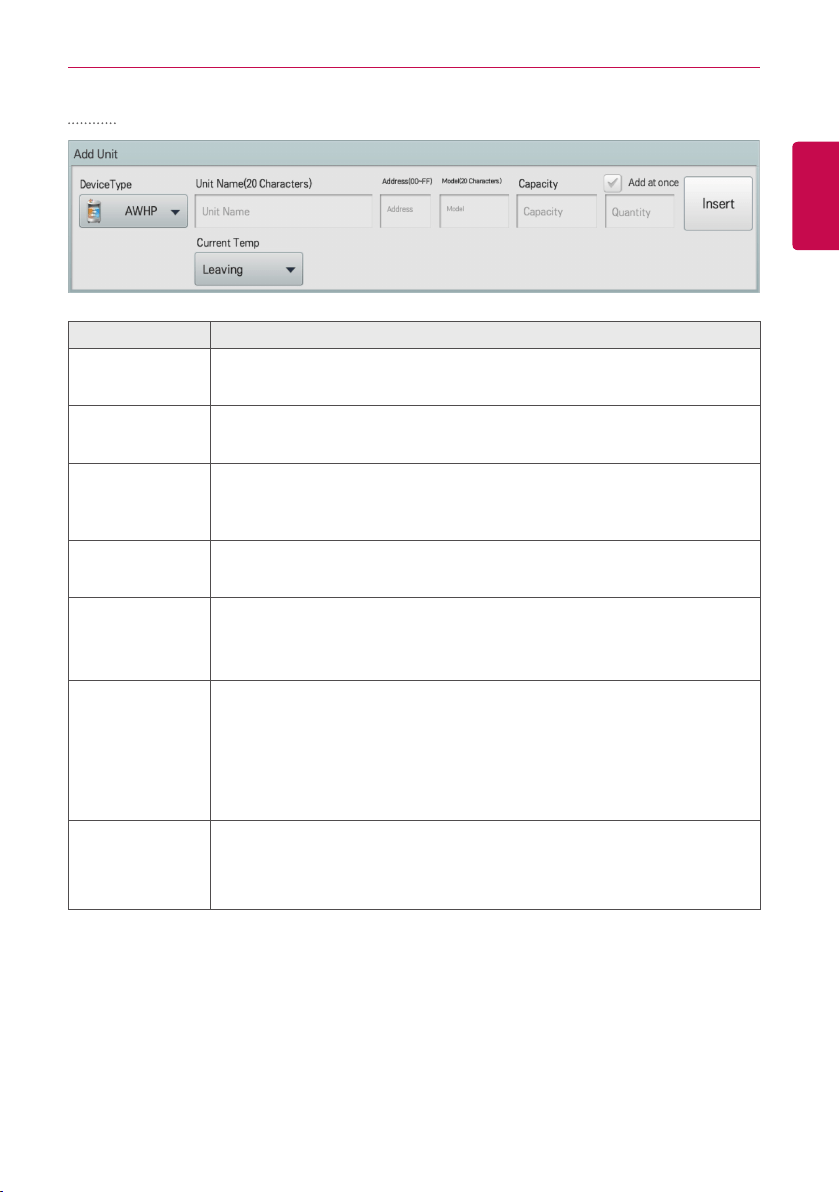
109
ENGLISH
USING THE PROGRAM
AWHP
Item Description
Device Type
Select a device type.
y AWHP
Unit Name
(20 Characters)
Enter the device name.
y Up to 20 characters.
Address
(00-FF)
Type the central control address of the device.
y A central control address value is a number between 00 and FF. You
cannot type the same value for similar devices.
Model
(20 Characters)
Type the device model.
y Up to 20 characters.
Capacity
Type the maximum capacity in thousand BTUs for devices.
y Up to 5 characters.
y The capacity of the actual device cannot exceed the input value.
Add at once
y It is used when you need to add several devices of the same type.
y Select check box, input the desired number of devices, and the devices
are added at once, and the device name and address are automatically
increased.
(During the Add all, if duplicate address value occurs, the information
notice message for the duplicate address is displayed.)
Based on
the current
temperature
display
Select the current temperature display base(water outlet/water inlet/indoor)
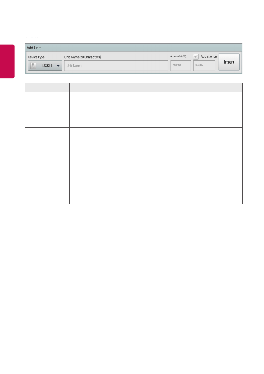
110
ENGLISH
USING THE PROGRAM
DOKIT
Item Description
Device Type
Select a device type.
y DOKIT
Unit Name
(20 Characters)
Enter the device name.
y Up to 20 characters.
Address
(00-FF)
Type the central control address of the device.
y A central control address value is a number between 00 and FF. You
cannot type the same value for similar devices.
y You cannot enter a duplicate value for indoor devices and DOKIT.
Add at once
y It is used when you need to add several devices of the same type.
y Select check box, input the desired number of devices, and the devices
are added at once, and the device name and address are automatically
increased.
(During the Add all, if duplicate address value occurs, the information
notice message for the duplicate address is displayed.)
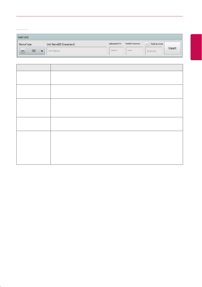
111
ENGLISH
USING THE PROGRAM
DO, DI
Item Description
Device Type
Select a device type.
y DO, DI
Unit Name
(20 Characters)
Enter the device name.
y Up to 20 characters.
Address
(00-FF)
Type the central control address of the device.
y A central control address value is a number between 00 and FF. You
cannot type the same value for similar devices.
Model
(20 Characters)
Type the device model.
y Up to 20 characters.
Add at once
y It is used when you need to add several devices of the same type.
y Select check box, input the desired number of devices, and the devices
are added at once, and the device name and address are automatically
increased.
(During the Add all, if duplicate address value occurs, the information
notice message for the duplicate address is displayed.)
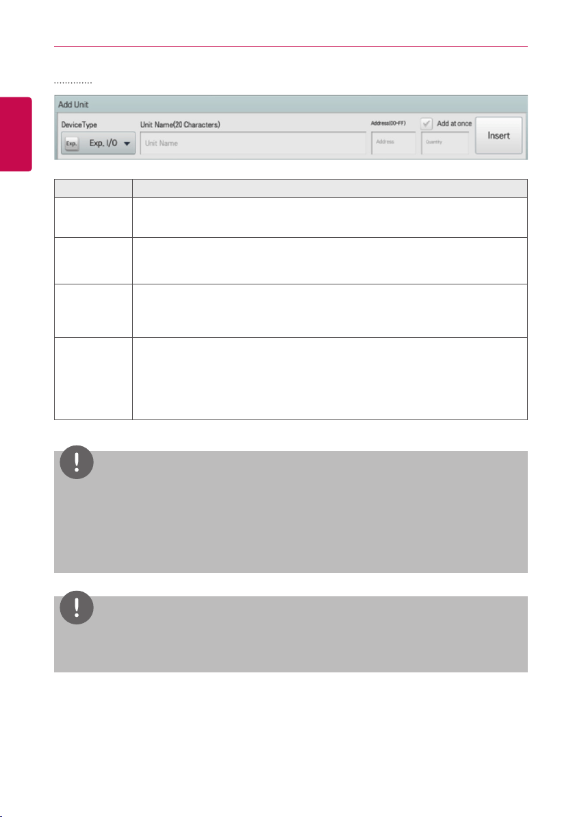
112
ENGLISH
USING THE PROGRAM
Exp.I/O
Item Description
Device Type
Select a device type.
y ACS I/O, AO I/O, UI I/O, DO I/O, DI I/O
Unit Name
(20
Characters)
Enter the device name.
y Up to 20 characters.
Address
(00-FF)
Type the central control address of the device.
y A central control address value is a number between 00 and FF. You cannot
type the same value for similar devices.
Add at once
y It is used when you need to add several devices of the same type.
y Select check box, input the desired number of devices, and the devices are
added at once, and the device name and address are automatically increased.
(During the Add all, if duplicate address value occurs, the information notice
message for the duplicate address is displayed.)
NOTES
y
The detail ports of Exp.I/O can be modified during device edit. For detail setting of Exp.I/O,
refer to
Exp.I/O Detail Setting
.
y
After registering or changing Exp.I/O device, the AC S IV Controller must be rebooted.
y
Be sure to perform a database backup prior to Auto addressing. Auto addressing does not find
any I/O Modules or points created from previous installation.
NOTES
Address of the products linked to the MODBUS communication system recommend a number
between 01~F7.
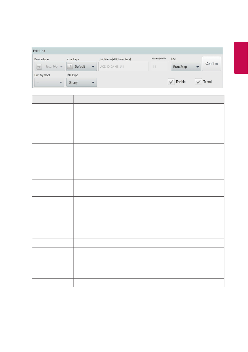
113
ENGLISH
USING THE PROGRAM
■ Exp.I/O Detail Setting
• UI
Item Description
Icon Type Select an icon type
Unit Name
(20 Characters)
Enter the device name.
y Up to 20 characters.
Address
It is automatically input according to Exp.I/O address, and it cannot be
changed.
Use
Select device usage
y Status information: run/stop, short/open, alarm/normal, close/open,
tun on/off, occupancy/vacancy
y Number information: temperature, humidity, open, level, operation
ratio, concentration, pressure
Unit Symbol*
Select unit symbol
y It is automatically selected according to the usage selection.
I/O Type Select I/O type (Binary or VOL, CUR, PT1000, NTC10K, NI1000)
Min.*
Input minimum value
y You can input up to 5 digits
Max.*
Input maximum value
y You can input up to 5 digits
Range* Select range if voltage on current input is required.
Correction*
Input correction value
y You can input up to 5 digits
Enable
During Exp.I/O registration, 14 Points are available for registration, the
enable check box must be selected to enable use.
Trend Save the value in the history at every designated interval (15 minutes).
* Only when I/O type is VOL, CUR, PT1000, NTC10K, or NI1000, the corresponding button is
displayed.
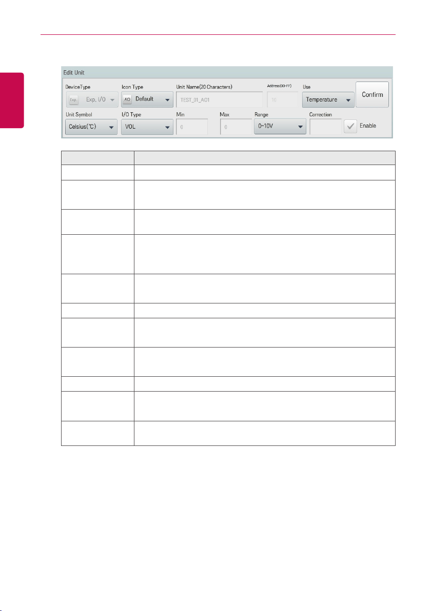
114
ENGLISH
USING THE PROGRAM
• AO
Item Description
Icon Type Select a icon type
Unit Name
(20 Characters)
Enter the device name.
y Up to 20 characters.
Address
It is automatically input according to Exp.I/O address, and it cannot be
changed.
Use
Select device usage
y Number information: temperature, humidity, open, level, operation
ratio, concentration, pressure
Unit Symbol*
Select unit symbol
y It is automatically selected according to the usage selection.
I/O Type Dedicated VOL
Min.*
Input minimum value
y You can input up to 5 digits
Max.*
Input maximum value
y You can input up to 5 digits (Maximum two step AO output)
Range* Select signal output required 0-10 or 2-10 VDC.
Correction*
Input correction value
y You can input up to 5 digits
Enable
During Exp.I/O registration, 14 Points are available for registration, the
enable check box must be selected to enable use.
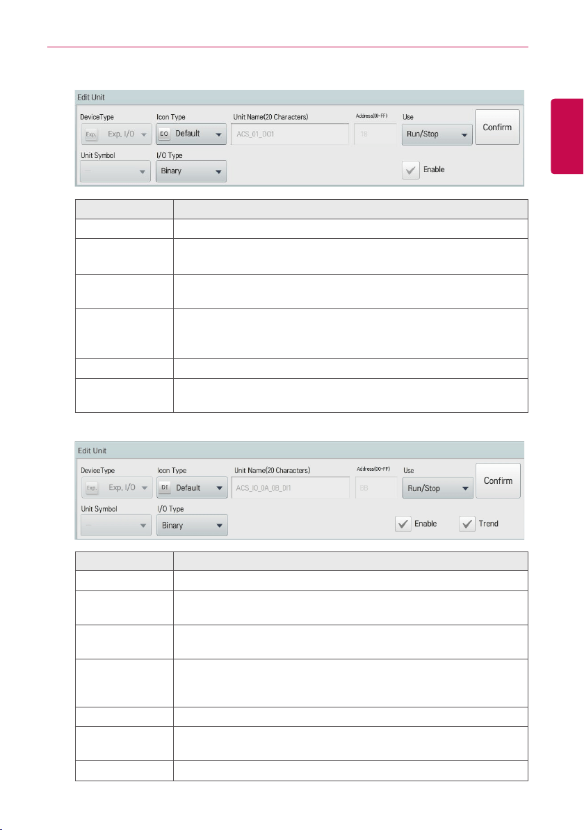
115
ENGLISH
USING THE PROGRAM
• DO
Item Description
Icon Type Select a icon type
Unit Name
(20 Characters)
Enter the device name.
y Up to 20 characters.
Address
It is automatically input according to Exp.I/O address, and it cannot be
changed.
Use
Select device usage
y Status information: run/stop, short/open, alarm/normal, close/open,
tun on/off, occupancy/vacancy
I/O Type Dedicated Binary Output
Enable
During Exp.I/O registration, 14 Points are available for registration, the
enable check box must be selected to enable use.
• DI
Item Description
Icon Type Select a icon type
Unit Name
(20 Characters)
Enter the device name.
y Up to 20 characters.
Address
It is automatically input according to Exp.I/O address, and it cannot be
changed.
Use
Select device usage
y Status information: run/stop, short/open, alarm/normal, close/open,
tun on/off, occupancy/vacancy
I/O Type Dedicated Binary Input
Enable
During Exp.I/O registration, 14 Points are available for registration, the
enable check box must be selected to enable use.
Trend Store the value in the Event Log every 15 minutes.

116
ENGLISH
USING THE PROGRAM
Managing Device
The following explains how to manage the information for a device added to the system.
Adding Groups
Follow these steps to add a new group.
1. In the main menu, click(touch) the [Installing] menu icon.
2. Click(Touch) the [Grouping] tab.
3. Click(Touch) the [Add Group] button.
4. When the window to type a group name is displayed, enter a group name and click(touch) the
[Confirm] button.
• The group is added to the group list.
5. In Grouping, click(touch) the group added in Step 4.
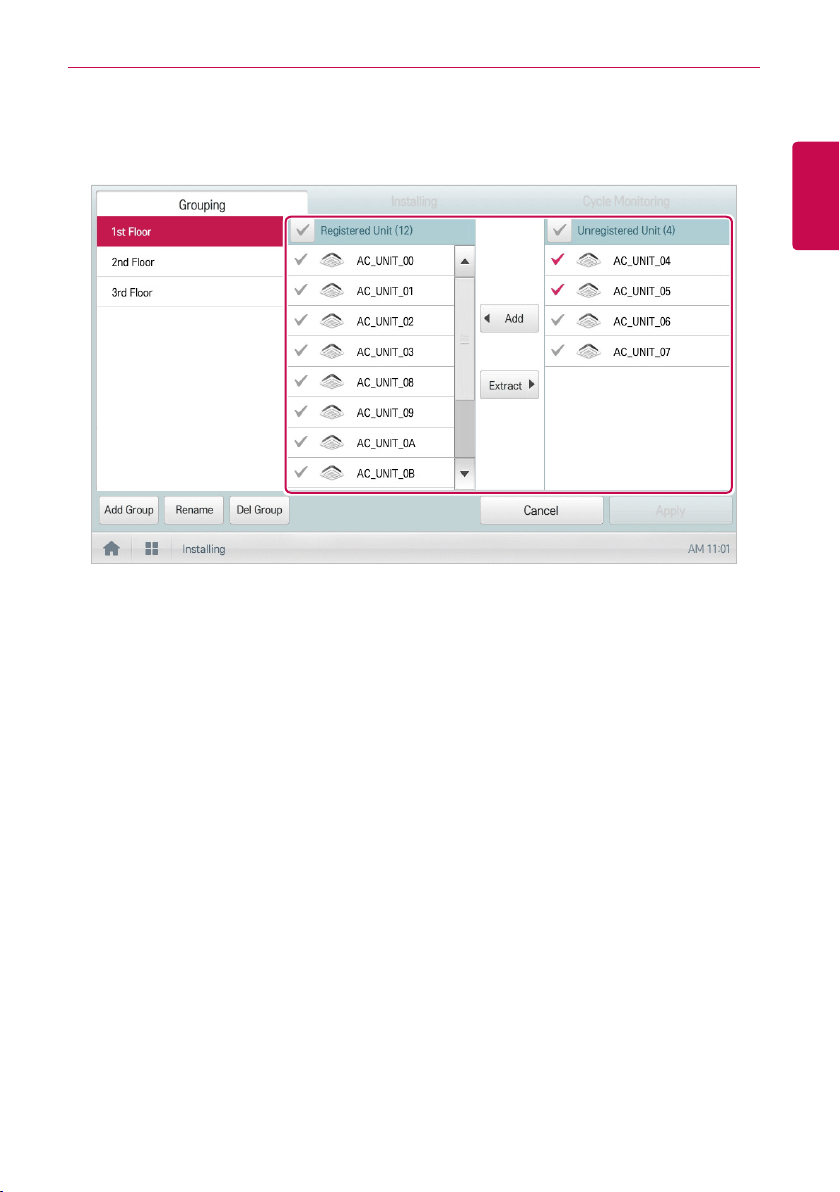
117
ENGLISH
USING THE PROGRAM
6. In the non-registered device area, click(touch) a device to add to the new group and click(touch)
the [Add] button.
• The selected device is moved to the registered device area.
7. To complete group creation, click(touch) the [Apply] button.
• When all non-registered devices are registered, the [Apply] button is enabled.
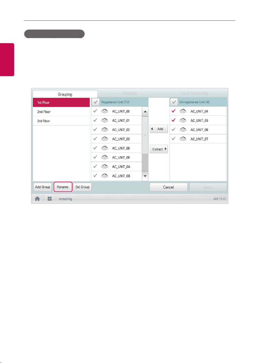
118
ENGLISH
USING THE PROGRAM
Changing Group Name
You can change the name of a registered group as follows.
1. In the main menu, click(touch) the [Installing] menu icon.
2. Click(Touch) the [Grouping] tab.
3. In the device management list, click(touch) a group whose name you want to change and
click(touch) the [Rename] button.
4. Enter a new group name and click(touch) the [Confirm] button.
• The group name is changed.
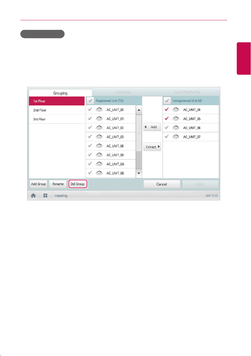
119
ENGLISH
USING THE PROGRAM
Deleting Groups
You can delete a registered group.
1. In the main menu, click(touch) the [Installing] menu icon.
2. Click(Touch) the [Grouping] tab.
3. In the device management list, click(touch) a group to be deleted and click(touch) the [Del Group]
button.
4. When you are prompted to confirm the deletion, click(touch) the [Confirm] button.
• The selected group is deleted and the tab removed.
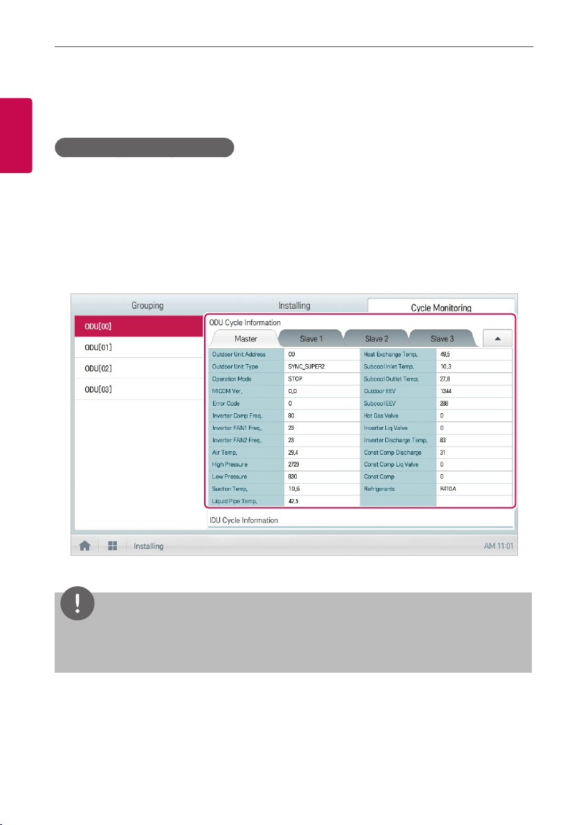
120
ENGLISH
USING THE PROGRAM
Cycle Monitoring
It is the description on how to view indoor/outdoor unit cycle information.
Outdoor unit cycle information
You can view outdoor unit cycle information.
1. In the main menu, click(touch) the [Installing] menu icon. (if available)
2. Click(touch) [Cycle Monitoring] tab.
3. In device list, click(touch) the device to view.
4. Click(touch) outdoor unit cycle information.
• Master/slave outdoor unit information is displayed.
NOTES
Some categories of the corresponding menu may not be displayed or menu name may be
different according to the function of the product.
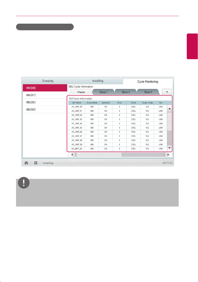
121
ENGLISH
USING THE PROGRAM
Indoor unit cycle information
You can view indoor unit cycle information.
1. In the main menu, click(touch) the [Installing] menu icon.
2. Click(touch) [View cycle] tab.
3. In device list, click(touch) the device to view.
4. On the top right of the ACS IV Controller screen, click(touch) the [▲] button.
• Information on all indoor units connected to the outdoor unit is displayed.
NOTES
Some categories of the corresponding menu may not be displayed or menu name may be
different according to the function of the product.
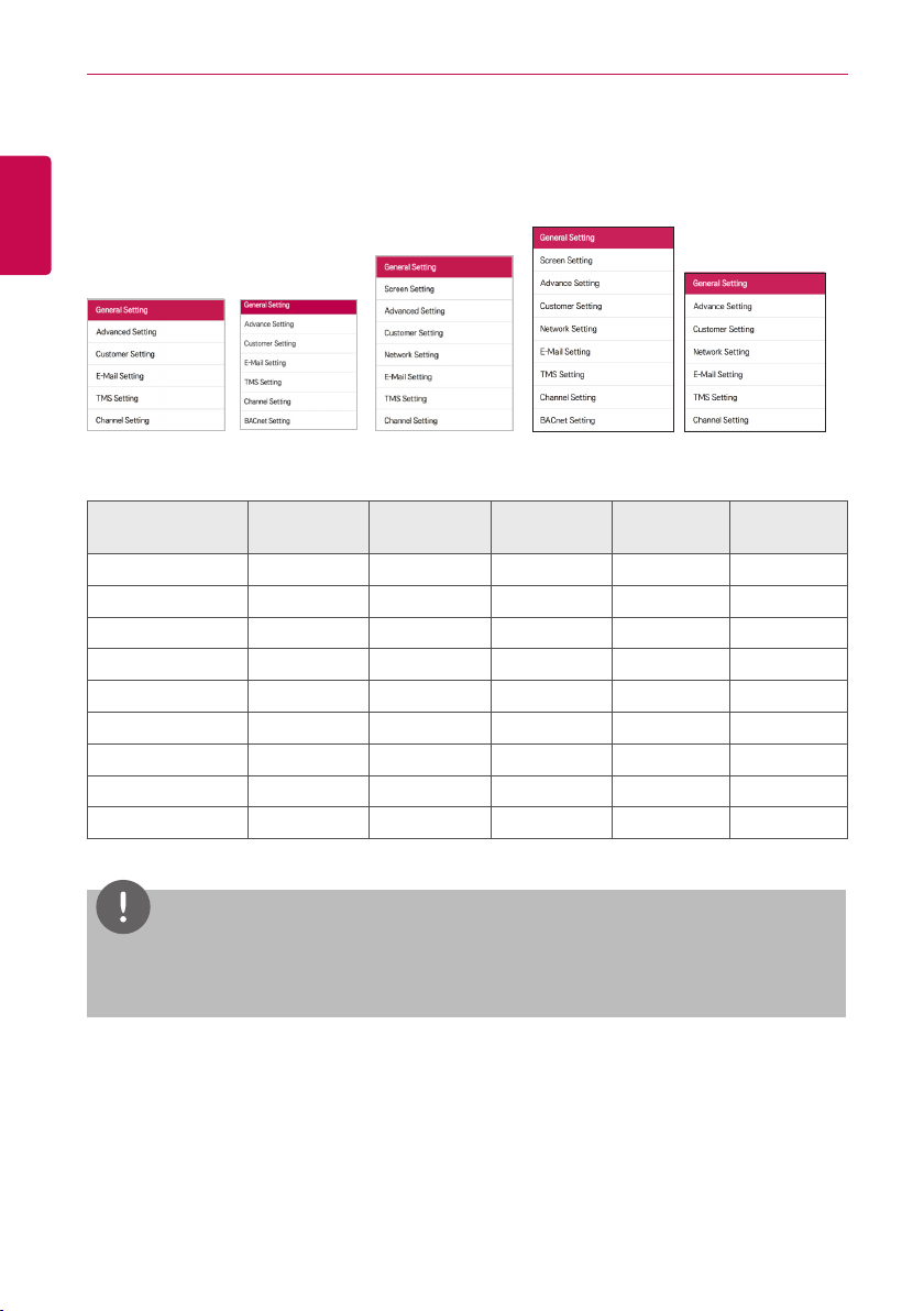
122
ENGLISH
USING THE PROGRAM
Environment
The following explains how to configure the system environment for user convenience and how to
check an already configured environment.
<ACP IV> <ACP BACnet> <AC Smart IV> <AC Smart BACnet> <ACP Lonworks>
Item ACP IV ACP BACnet AC Smart IV
AC Smart
BACnet
ACP
Lonworks
General Setting O O O O O
Screen Setting X X O O X
Advance Setting O O O O O
Customer Setting O O O O O
Network Setting X X O O O
E-Mail Setting O O O O O
TMS Setting O O O O O
Channel Setting O O O O O
BACnet Setting X O X O X
NOTES
After change the environment setup, it is recommended to use after deleting the cache in the
explorer.
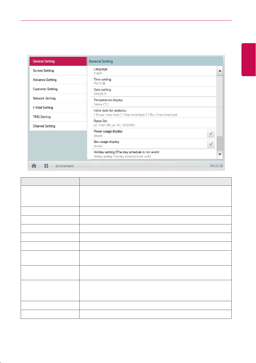
123
ENGLISH
USING THE PROGRAM
General Setting
The following explains how to configure the general system environments.
Item Description
Language
Configures the language displayed on the screen
(한국어(Korean)/English/Italiano/Españo/Português/pусскийязык/
Français/DeutschSprache/Türkçe/JęzykPolski/中文)
Time setting Configures system time.
Date setting Configures system date.
Temperature display Configures the temperature unit.
Initial date for statistics Configures the reference date for querying statistical data.
Rates set Configures the charge per 1kWh, per 1kL and currency used.
Power Consumption
Display
Set up the display of the power consumption usage in the energy
report.
Gas Consumption
Display
Set up the display of the gas consumption in the energy report.
Holiday setting
(The day schedule is not
work)
Selects the days for which schedules are not be applied.
Site Name Setup Set up the site name to be displayed on the home screen.
Version Information Displays the current software version.
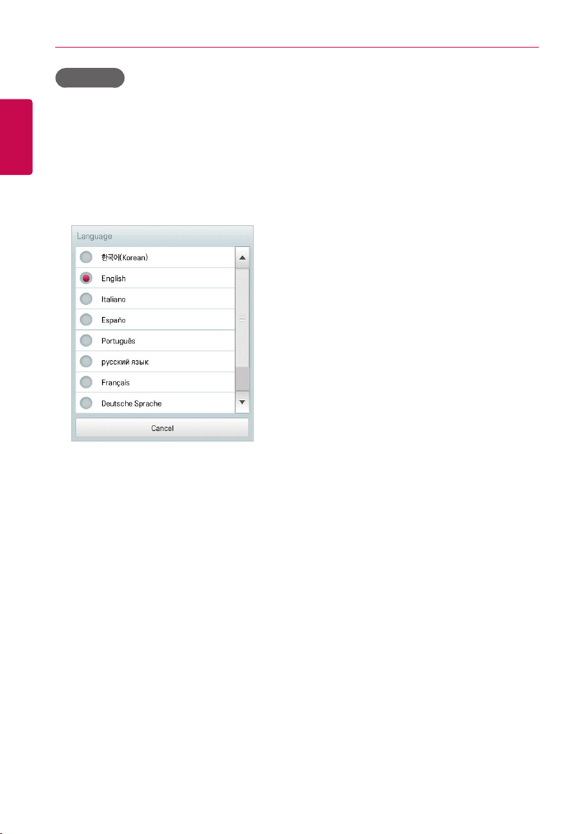
124
ENGLISH
USING THE PROGRAM
Language
Configures the language displayed on the screen.
1. In the main menu, click(touch) the [Environment] menu icon.
2. In the settings list, click(touch) General Setting.
3. In the detailed settings list, click(touch) Language.
4. Click(Touch) a language you want.
• The selected language is applied as the system language.
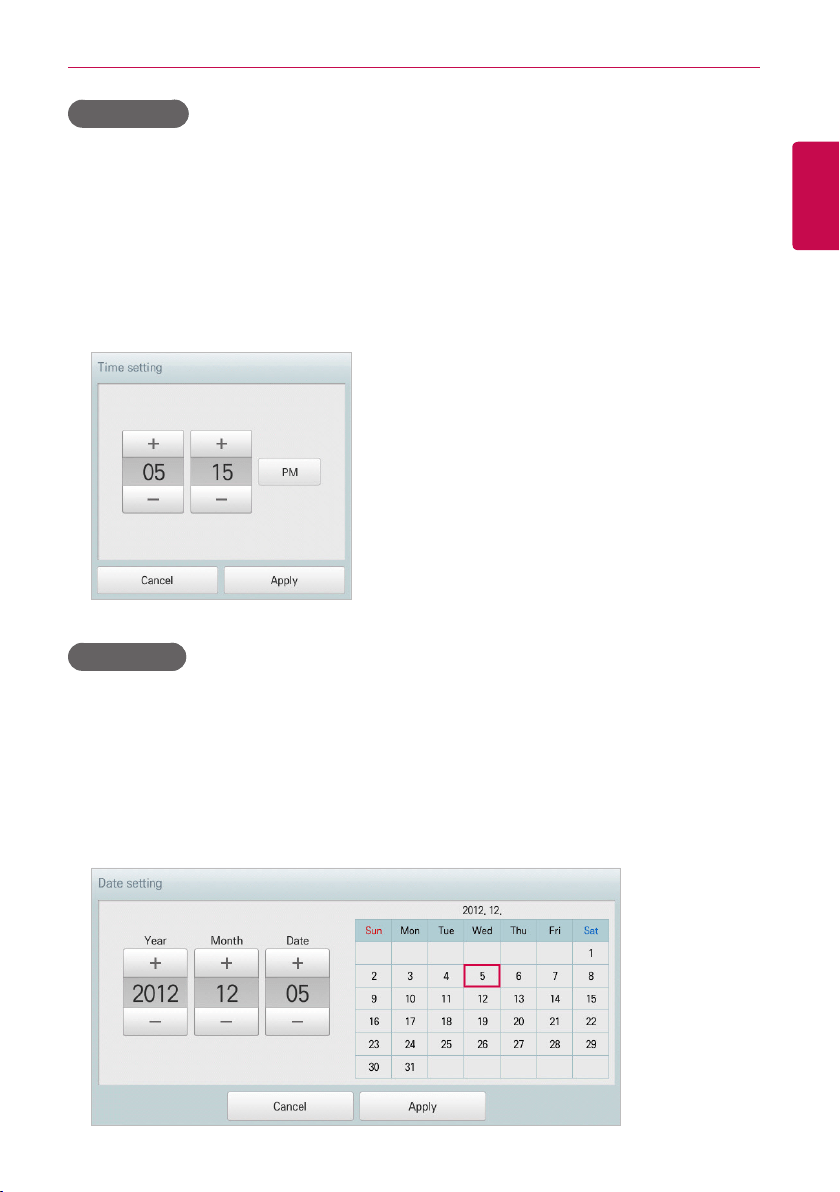
125
ENGLISH
USING THE PROGRAM
Time setting
You can configure the time used for the system as follows.
1. In the main menu, click(touch) the [Environment] menu icon.
2. In the Settings list, click(touch) General Setting.
3. In the detailed settings list, click(touch) Time setting.
4. Apply the current time and click(touch) the [Apply] button.
• Click(Touch) [+]/[-] button to select the time.
• Click(Touch) the [AM]/[PM] button to select before or after midday.
Date setting
You can configure the date used for the system as follows.
1. In the main menu, click(touch) the [Environment] menu icon.
2. In the Settings list, click(touch) General Setting.
3. In the detailed settings list, click(touch) Date setting.
4. Modify the program configuration information and click(touch) the [Apply] button.
• Use [+]/[-] button to select a date.
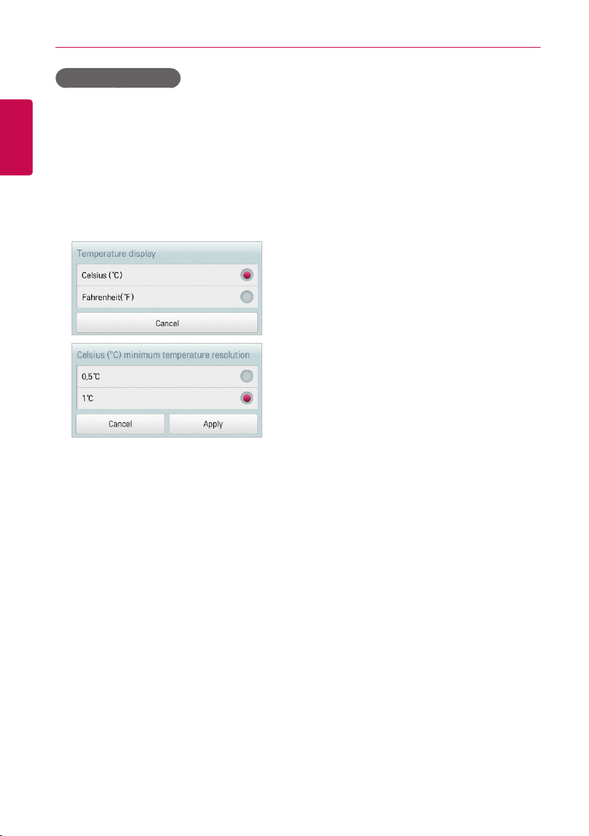
126
ENGLISH
USING THE PROGRAM
Temperature display
You can select a temperature system as follows.
1. In the main menu, click(touch) the [Environment] menu icon.
2. In the Settings list, click(touch) General Setting.
3. In the detailed settings list, click(touch) Temperature display.
4. Click(Touch) the temperature system you want.
• When selecting the Celsius system, in the Minimum Celsius(°C) Temperature window,
click(touch) the minimum temperature.
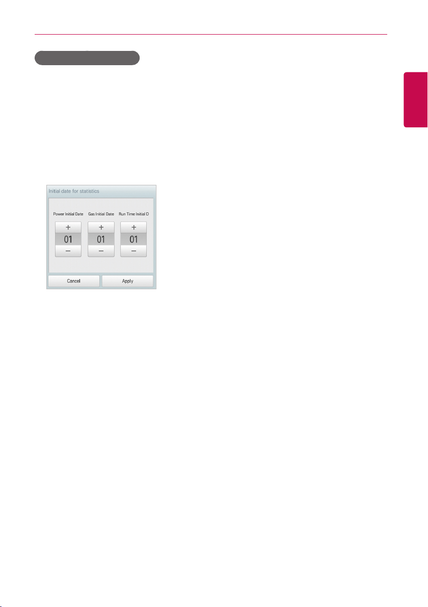
127
ENGLISH
USING THE PROGRAM
Initial date for statistics
Statistics Reference Date is the date for calculating the indoor unit's operation time by month.
The operation time from this date through the previous date to the same date of the next month is
calculated and provided as statistical data. You can configure Statistics Reference Date as follows.
1. In the main menu, click(touch) the [Environment] menu icon.
2. In the Settings list, click(touch) General Setting.
3. In the detailed settings list, click(touch) Initial date for statistics.
4. Touch [+]/[-] button to separately set the desired power base date/gas base date/operation hours
base date, and click(touch) [Apply] button.
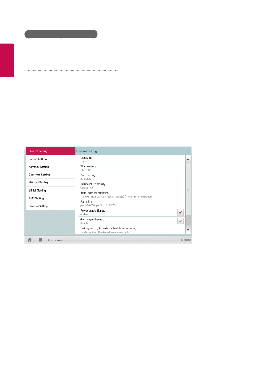
128
ENGLISH
USING THE PROGRAM
Power Consumption Display
Set up whether power consumption is displayed in the energy report.
Setting up the power consumption display
The method to display power consumption in the energy report is as follows.
1. In the main menu, click(touch) the [Environment] menu icon.
2. In the Settings list, click(touch) General Setting.
3. Click(touch) the Power Consumption Display in the detailed setting list.
4. When Enable is selected, the check box becomes red, and power consumption can be referred
in the energy report menu (when linked to PDI).
5. When Disable is selected, the check box becomes gray, and power consumption cannot be
referred in the energy report menu.
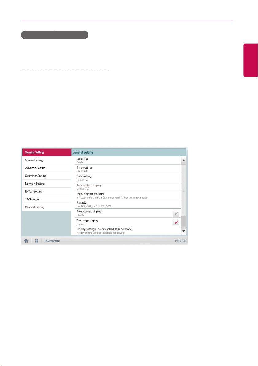
129
ENGLISH
USING THE PROGRAM
Gas Consumption Display
Set up whether gas consumption is displayed in the energy report.
Setting up the gas consumption display
The method to display gas consumption in the energy report is as follows.
1. In the main menu, click(touch) the [Environment] menu icon.
2. In the Settings list, click(touch) General Setting.
3. Click(touch) the Gas Consumption Display in the detailed setting list.
4. When Enable is selected, the check box becomes red, and gas consumption can be referred in
the energy report menu (when linked to PDI).
5. When Disable is selected, the check box becomes gray, and gas consumption cannot be
referred in the energy report menu.
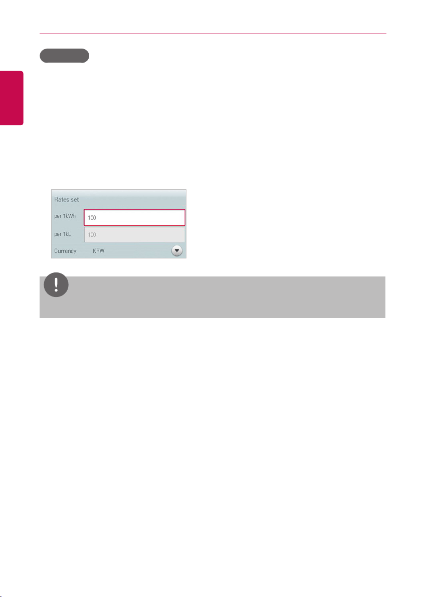
130
ENGLISH
USING THE PROGRAM
Rates Set
You can configure the charge per kWh and the currency as follows.
1. In the main menu, click(touch) the [Environment] menu icon.
2. In the Settings list, click(touch) General Setting.
3. In the detailed settings list, click(touch) Rates set.
4. Configure the charge/kWh configuration information and click(touch) [Apply] button.
• rates per(1kWh): Charge per 1kWh.
• rate per(1kL): Charge per 1kL.
• Currency: Click(Touch) [▼] button to select the desired currency.
NOTES
1 kL is equal to 1m
3
.
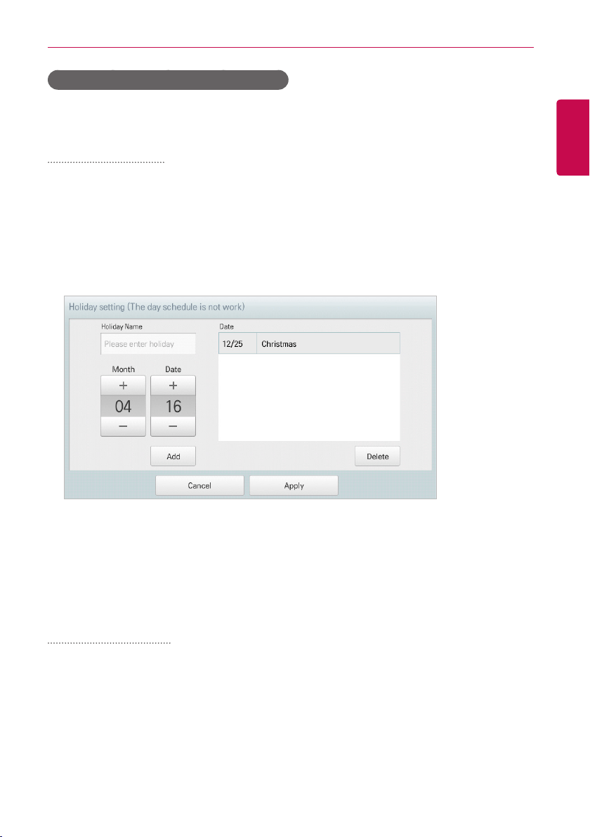
131
ENGLISH
USING THE PROGRAM
Holiday setting(Supercedes day schedule)
The following explains how to register an exception date or how to delete a registered date.
Adding Exception Date
You can add a desired exception date as follows.
1. In the main menu, click(touch) the [Environment] menu icon.
2. In the Settings list, click(touch) General Setting.
3. In the detailed settings list, click(touch) Holiday setting(Days in which the regular schedule is
ignored).
• The Exception Date Configuration window opens.
4. Type a name for the exception date in the exception date input box.
5. [+]/[-] button to select an exception date.
6. To add the selected exception date, click(touch) the [Add] button.
• The exception date is registered on the exception date list.
7. To complete Exception Date Configuration, click(touch) the [Apply] button.
Deleting Exception Date
You can delete a registered exception date as follows.
1. In the main menu, click(touch) the [Environment]menu icon.
2. In the Settings list, click(touch) General Setting.
3. In the detailed settings list, click(touch) Holiday setting(Days in which the schedule is
ignored).
• The Exception Date Configuration window opens.
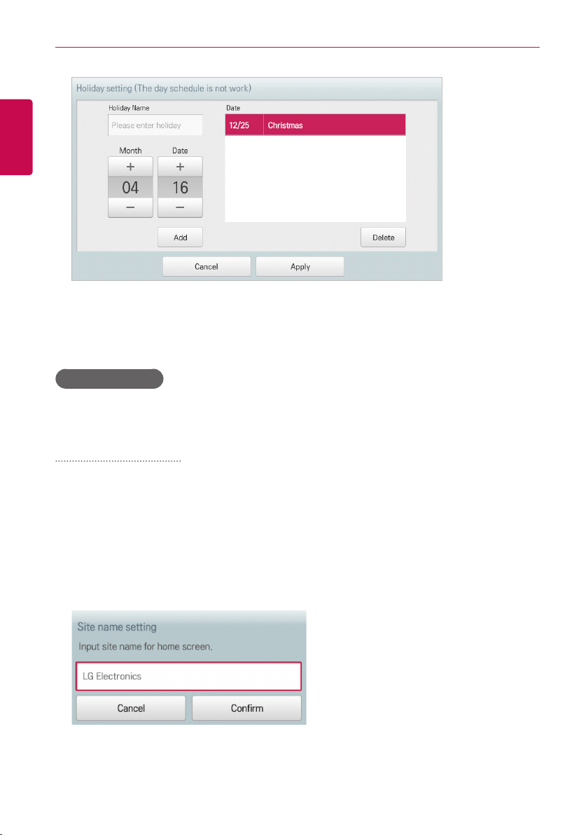
132
ENGLISH
USING THE PROGRAM
4. Click(Touch) an exception date in the exception date list, and click(touch) the [Delete] button.
5. To complete Exception Date Configuration, click(touch) the [Apply] button.
Site Name Setup
Setting up the site name to be displayed on the home screen.
Setting up the site name
The method to set up the site name is as follows.
1. In the main menu, click(touch) the [Environment] menu icon.
2. In the Settings list, click(touch) General Setting.
3. Click(touch) the Site Name Setup in the detailed setting list.
4. Input the site name to be set up in the site name input field.
5. Click(touch) the [Confirm] button to complete the site name setup.
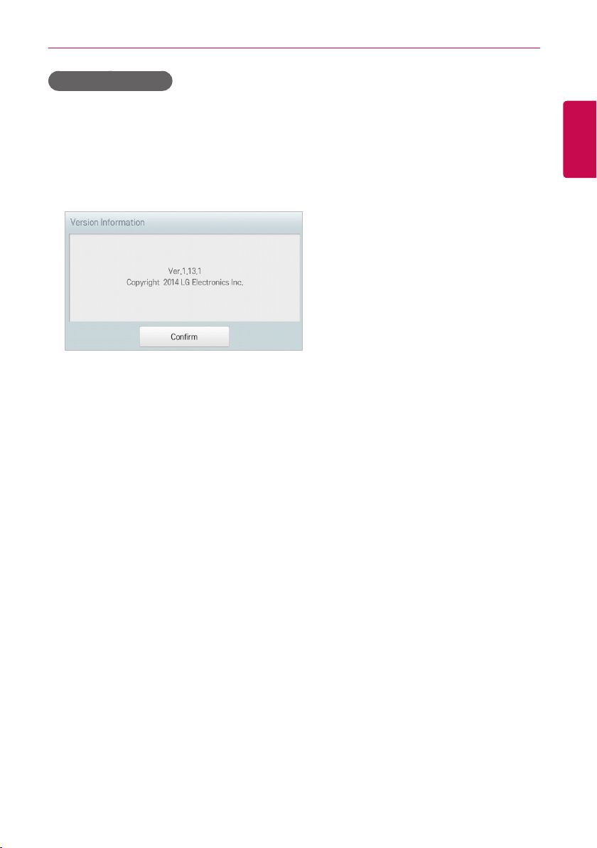
133
ENGLISH
USING THE PROGRAM
Version Information
You can check the current version of the software as follows.
1. In the main menu, click(touch) the [Environment] menu icon.
2. In the Settings list, click(touch) General Setting.
3. In the detailed settings list, click(touch) Version Information.
• The current version of the system is displayed in a popup window.
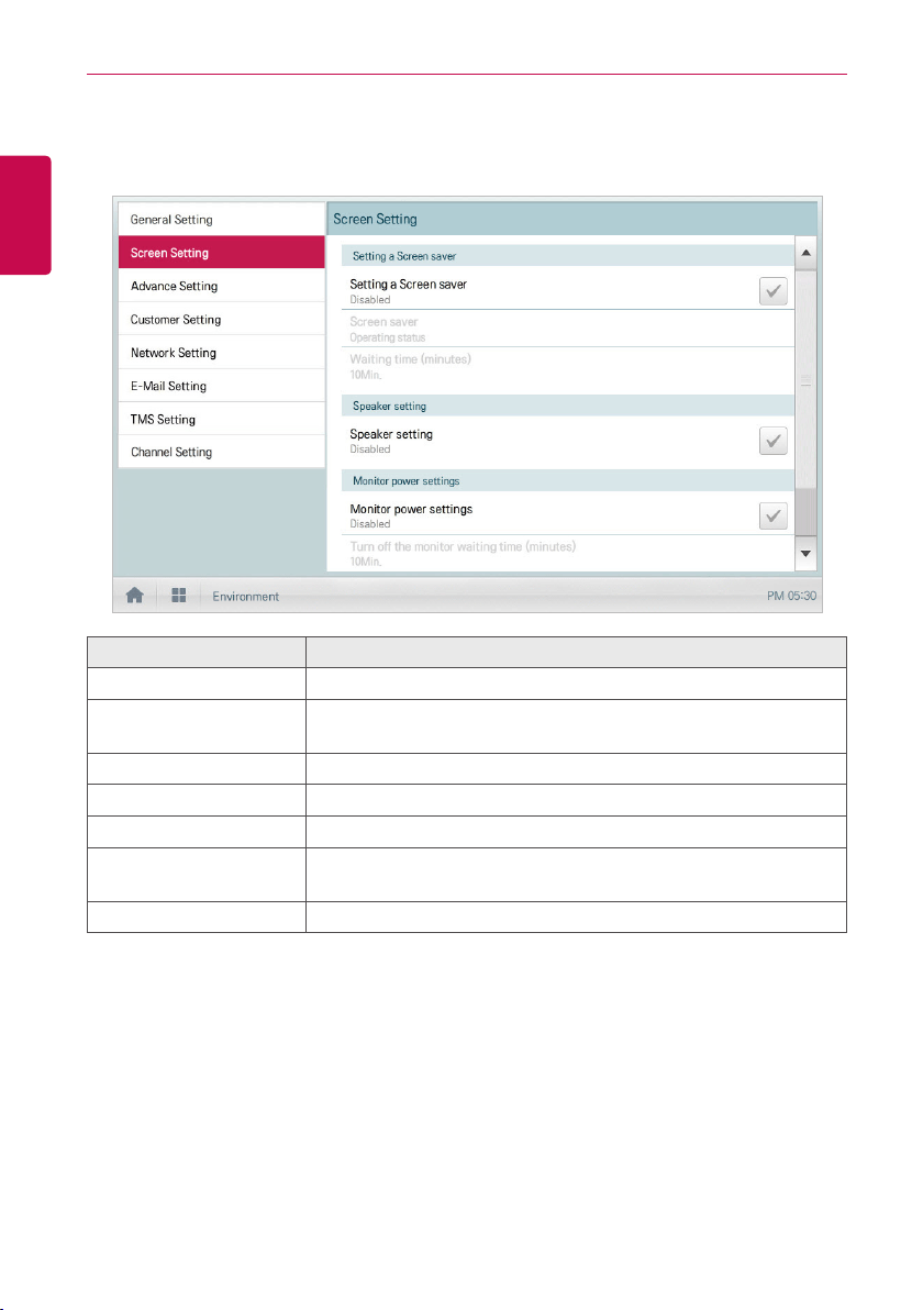
134
ENGLISH
USING THE PROGRAM
Screen Setting (AC Smart IV, AC Smart BACnet Only)
The following explains how to configure the use environment regarding the product screen.
Item Description
Setting a Screen saver Determines whether to use a screen saver
Screen saver
Configures information to be displayed on the screen saver
(operation status)
Waiting time (minutes) Select the standby time that the screen saver waits before operation.
Speaker setting Determines whether to use a speaker
Monitor power settings Determines whether to use monitor power-off function
Turn off the monitor
waiting time(minutes)
Selects the standby time that the monitor waits before turn-off
Calibrating the Screen Screen calibration for accurate click(touch)
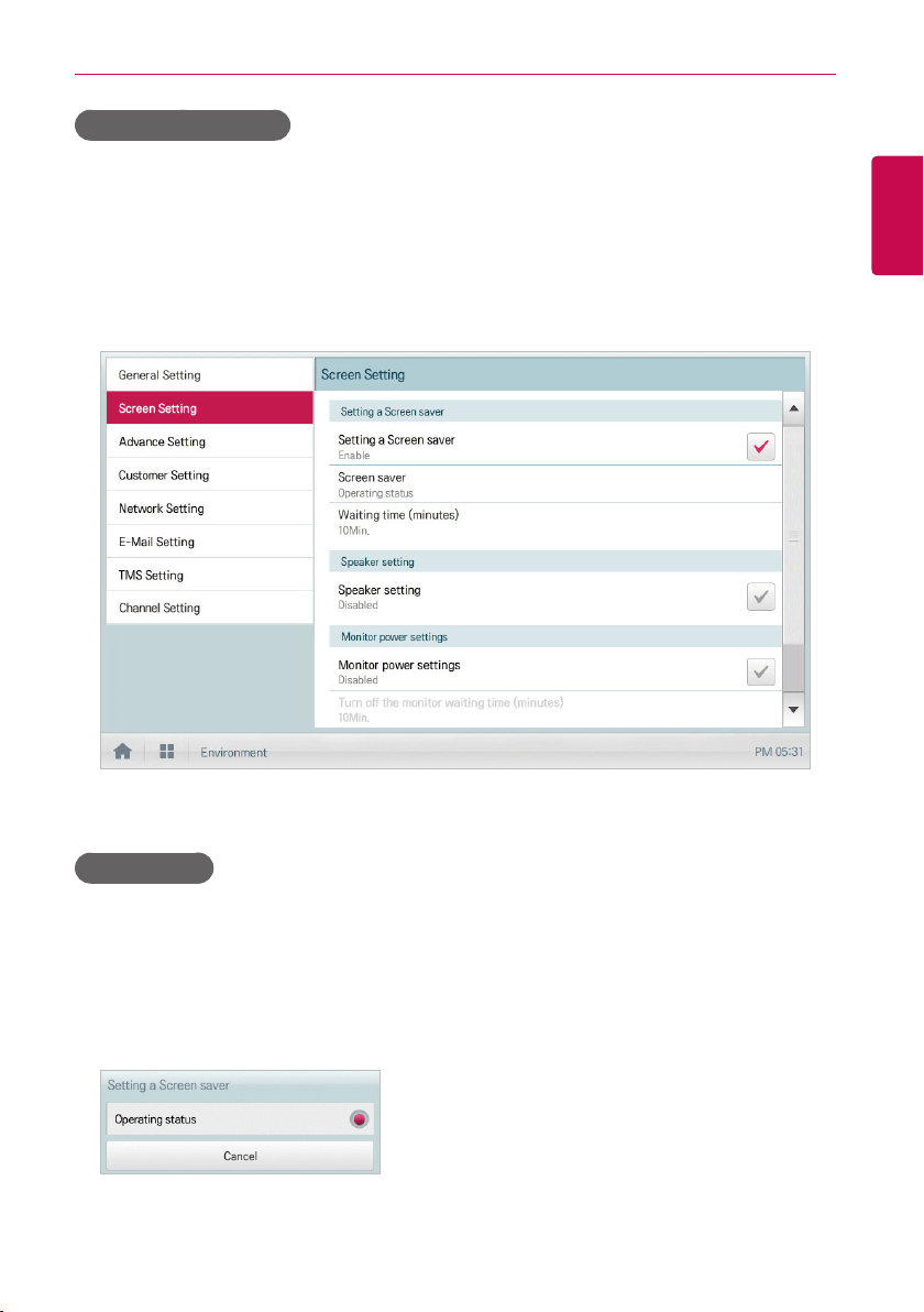
135
ENGLISH
USING THE PROGRAM
Setting a Screen saver
You can configure the screen saver as follows.
1. In the main menu, click(touch) the [Environment] menu icon.
2. In the Settings list, click(touch) Screen Setting.
3. In the detailed settings list, click(touch) Setting a Screen saver.
• Enable, the check box turns red and the Screen Saver and Waiting time (minutes) are
enabled.
Screen saver
You can set screen saver type as follows.
1. In the main menu, click(touch) the [Environment] menu icon.
2. In the Settings list, click(touch) Screen Setting.
3. In the detailed settings list, click(touch) Screen saver.
4. When screen protector setting window is displayed, click(touch) the desired screen saver.
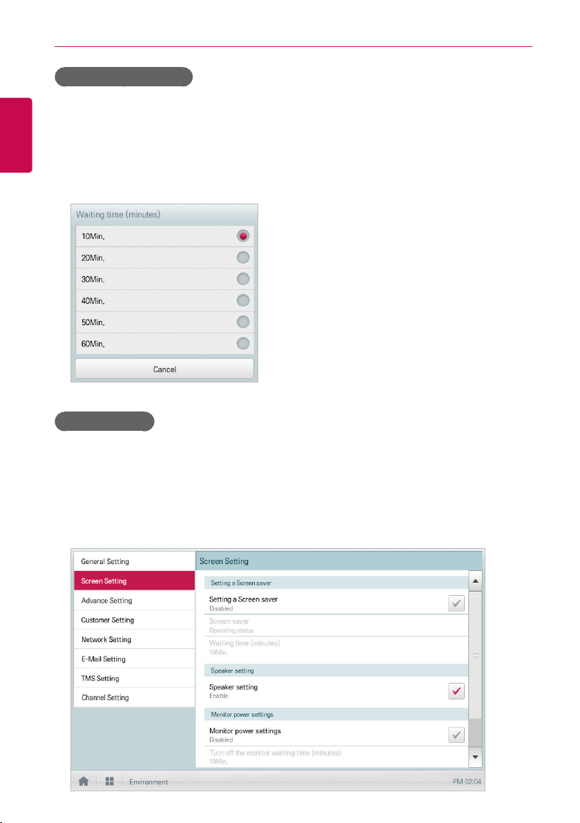
136
ENGLISH
USING THE PROGRAM
Waiting time (minutes)
You can configure the standby time that the screen saver waits before operation.
1. In the main menu, click(touch) the [Environment] menu icon.
2. In the Settings list, click(touch) Screen Setting.
3. In the detailed settings list, click(touch) the Waiting time (minutes).
4. In the Standby Time Configuration window, click(touch) the standby time.
Speaker setting
You can configure the speaker setting as follows.
1. In the main menu, click(touch) the [Environment] menu icon.
2. In the setting list, click(touch) Screen Setting.
3. In the detailed settings list, click(touch) Speaker setting.
• Enable, the check box turns red and the Speaker is enabled.
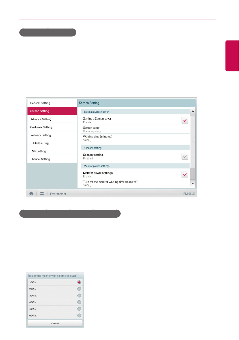
137
ENGLISH
USING THE PROGRAM
Monitor power settings
You can configure the monitor to turn off automatically, if the click(touch) screen is not used for a
certain period of time. You can configure this function as follows.
1. In the main menu, click(touch) the [Environment] menu icon.
2. In the Settings list, click(touch) Screen Setting.
3. In the detailed settings list, click(touch) Monitor power settings.
• Enable, the check box turns red and Turn off the monitor waiting time (minutes) is
enabled.
Turn off the monitor waiting time (minutes)
You can configure the monitor to turn off automatically, if the click(touch) screen is not used for a
certain period of time, as follows.
1. In the main menu, click(touch) the [Environment] menu icon.
2. In the Settings list, click(touch) Screen Setting.
3. In the detailed settings list, click(touch) Turn off the monitor waiting time (minutes).
4. Click(Touch) the standby time you desire.
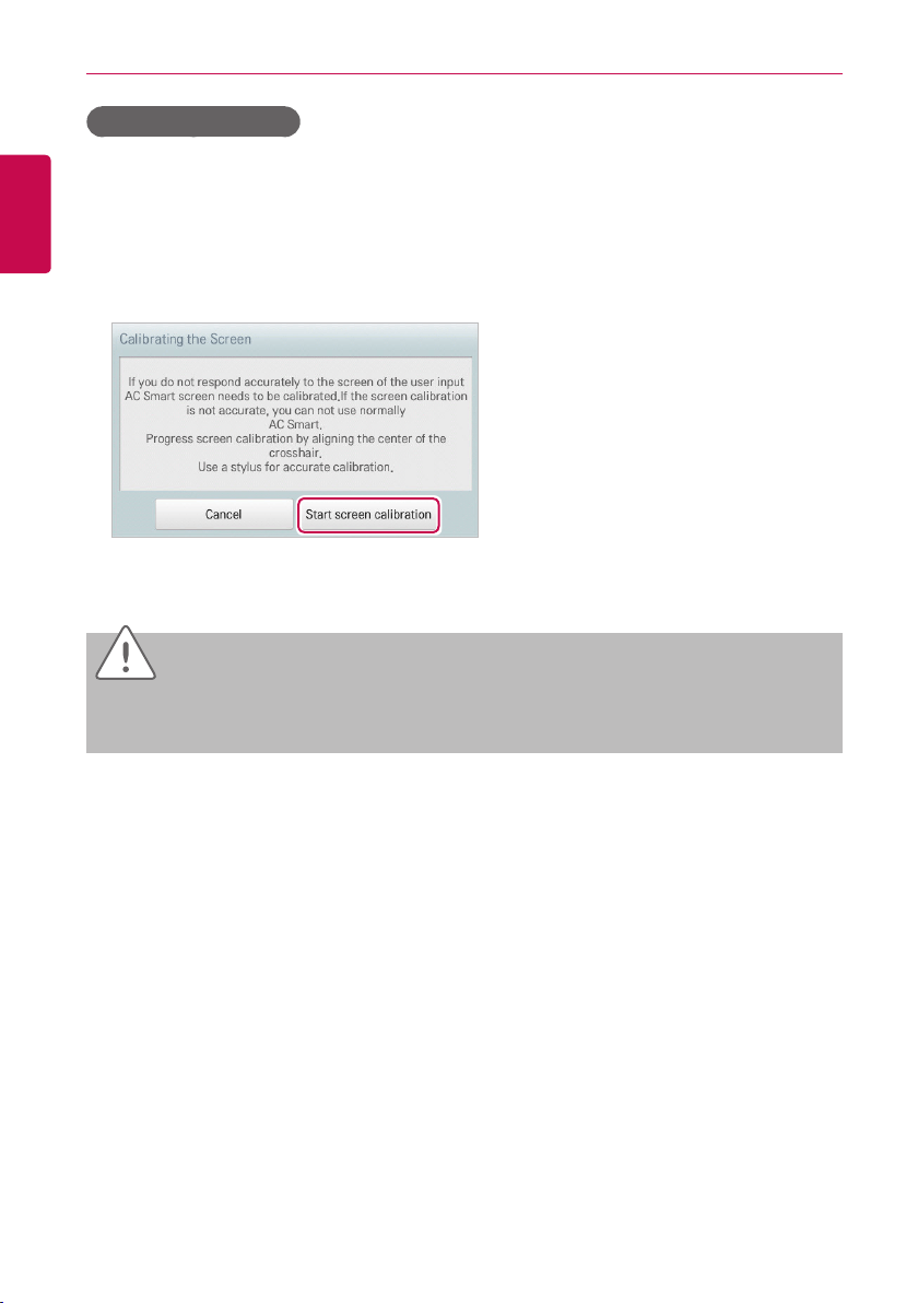
138
ENGLISH
USING THE PROGRAM
Calibrating the Screen
You can calibrate the screen for accurate click(touch) response as follows.
1. In the main menu, click(touch) the [Environment] menu icon.
2. In the Settings list, click(touch) Screen Setting.
3. In the detailed settings list, click(touch) Calibrating the Screen.
4. To start the screen calibration, click(touch) the [Start screen calibration] button.
5. When the crosses appear on the screen, click(touch) the center of each to calibrate.
Caution
If you touch too far from the center of the cross mark, you need to carry it out again after 15
seconds.
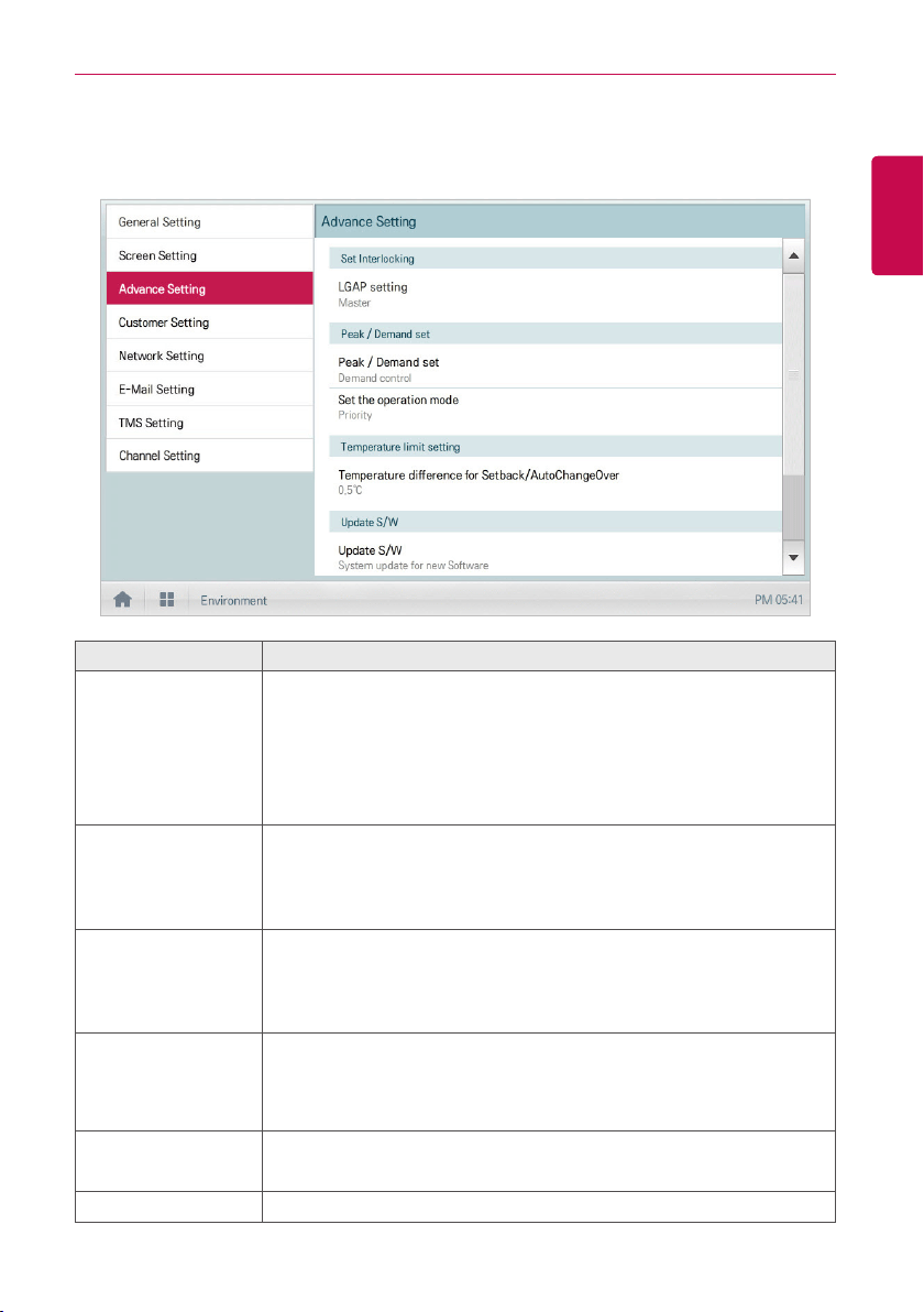
139
ENGLISH
USING THE PROGRAM
Advance Setting
The following explains how to configure the functions necessary for device operation.
Item Description
LGAP setting
(AC Smart IV Only)
y Master: ACS IV Controller is used independently.
y Slave: It shares the communication line with other ACS IV Controller
products.
(If multiple ACS IV Controllers are used, one must be selected as Master
and the others as Slave. In slave mode, some functions of Auto Search in
the Installing menu are not available.)
Peak/Demand set
y Peak Control: You can use the peak control feature in the auto logic
menu.
y Demand Control: You can use the demand control feature in the auto
logic menu.
Set the operation
mode
y Priority Control: In Peak/Demand Control menu, control the
devices based on the priority of the group.
y Outdoor Unit Capacity Control: In the Peak/Demand Control
menu, control the outdoor capacity rate per unit.
Temperature
difference
for Setback/
AutoChangeOver
[+]/[-] button to select the temperature gap.
Update S/W
y Software upgrade using a USB memory stick.
y Complete upgrade and restart the system.
DB backup Backup the DB onto a USB memory stick.
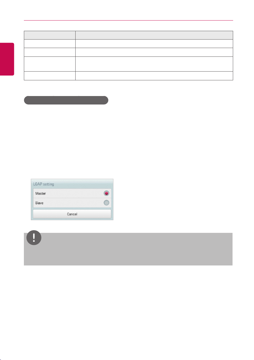
140
ENGLISH
USING THE PROGRAM
Item Description
Recovery DB Use the DB stored on the USB memory stick to restore the system.
Auto Mode Option Select a desired auto mode type.
Outdoor Unit Oil-
Return Operation
Determines whether to use outdoor unit oil-return operation.
System Restart Remote system restart.
LGAP setting (AC Smart IV Only)
ACS IV Controller can interface with another ACS IV Controller to control a device. You can
configure the interface type with other devices as follows.
1. In the main menu, click(touch) the [Environment] menu icon.
2. In the Settings list, click(touch) Advance Setting.
3. In the detailed settings list, click(touch) LGAP setting.
4. Click(Touch) a type you want.
• Master: ACS IV Controller is used independently.
• Slave: It shares the communication line with other ACS IV Controller products.
NOTES
If multiple ACS IV Controllers are used, one must be selected as Master and the others as
Slave.
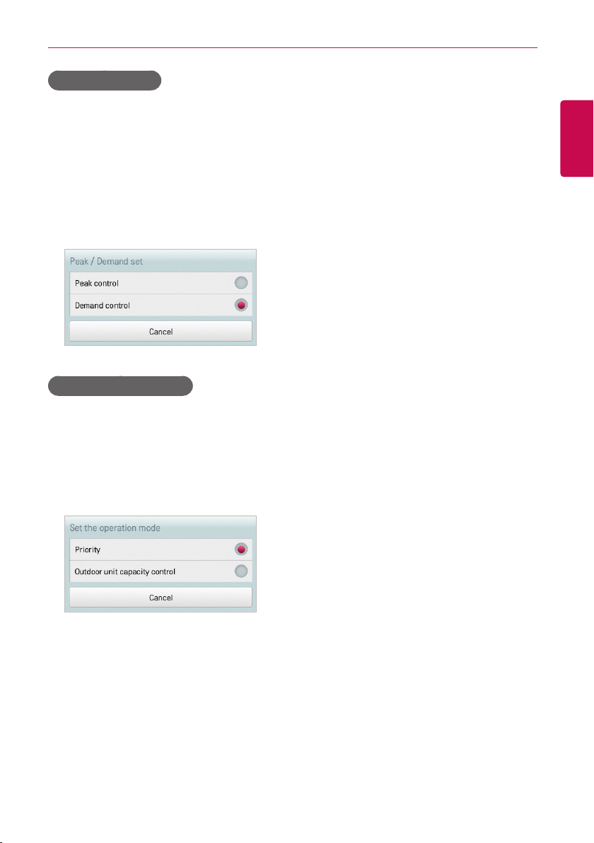
141
ENGLISH
USING THE PROGRAM
Peak/Demand set
You can select a control type to be used for auto logic.
1. In the main menu, click(touch) the [Environment] menu icon.
2. In the Settings list, click(touch) Advance Setting.
3. In the detailed settings list, click(touch) Peak/Demand set.
4. Click(Touch) a control type to be used for auto logic
• Peak Control: You can use the peak control feature in the auto logic menu.
• Demand Control: You can use the demand control feature in the auto logic menu.
Set the operation mode
You can configure the operation type as follows.
1. In the main menu, click(touch) the [Environment] menu icon.
2. In the Settings list, click(touch) Advance Setting.
3. In the detailed settings list, click(touch) Set the operation mode.
4. Click(Touch) an operation type you want.
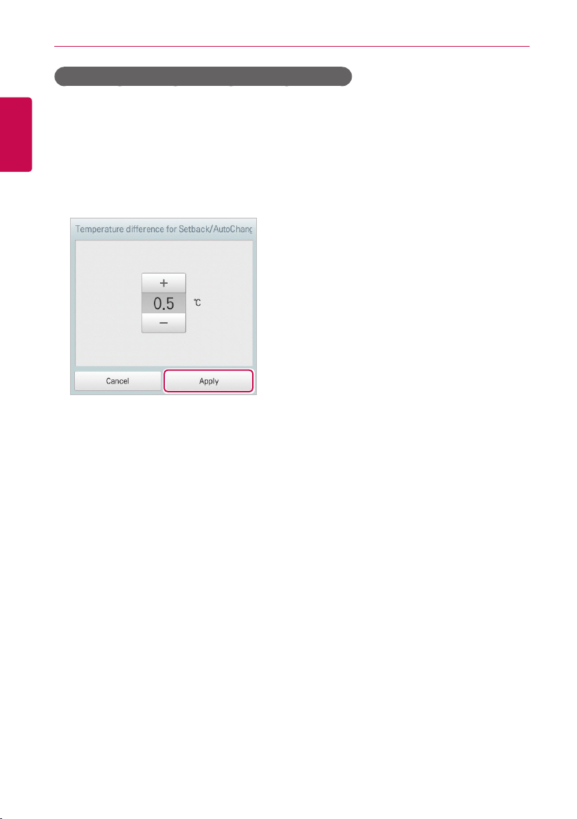
142
ENGLISH
USING THE PROGRAM
Temperature difference for Setback/AutoChangeOver
You can configure the temperature gap for auto changeover operation.
1. In the main menu, click(touch) the [Environment] menu icon.
2. In the Settings list, click(touch) Advance Setting.
3. In the detailed settings list, click(touch) Temperature difference for Setback/
AutoChangeOver.
4. [+]/[-] button to select a temperature gap you want and [Apply] button.
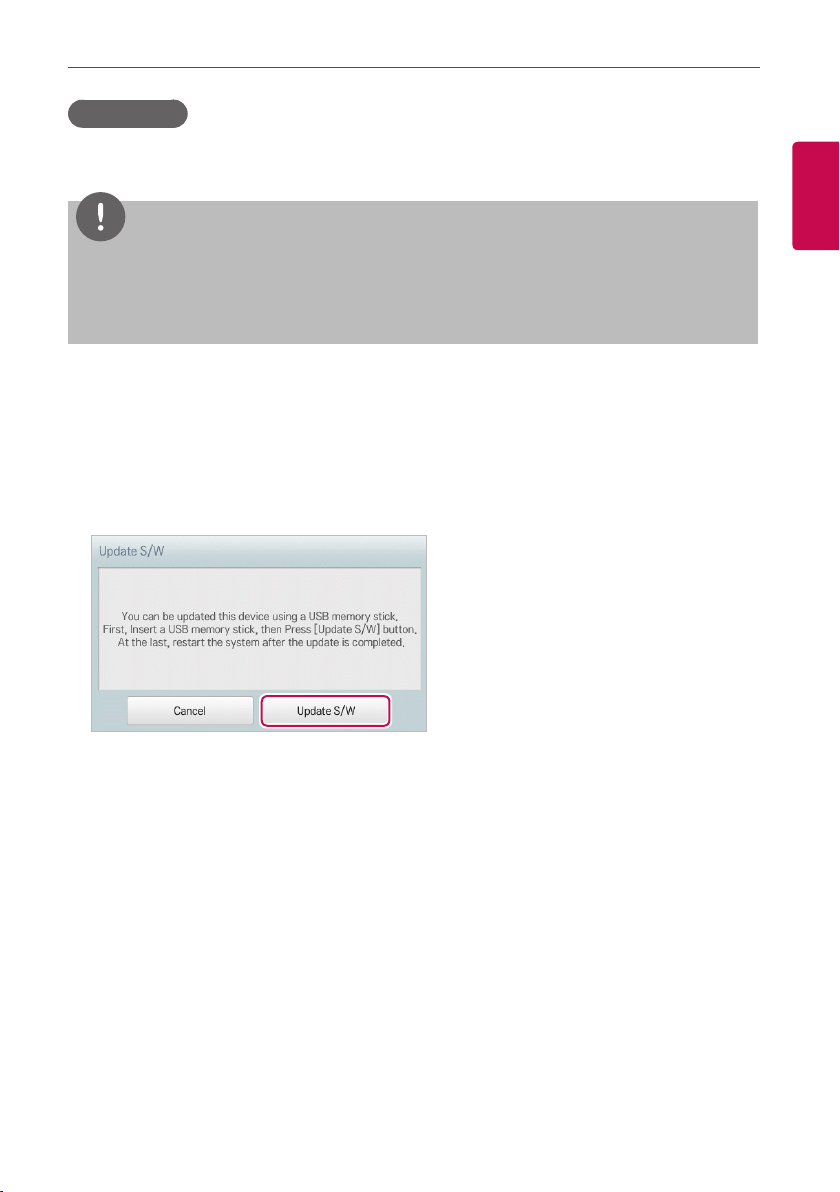
143
ENGLISH
USING THE PROGRAM
Update S/W
You can upgrade the current version of software as follows.
NOTES
y
To update the software, you need a USB memory stick which has
patch.tar.gz
file in the
ramdisk
folder.
y
For standard thumb drives, a USB to mini USB cable is required.
1. Connect the USB memory to ACS IV Controller.
2. In the main menu, click(touch) the [Environment] menu icon.
3. In the Settings list, click(touch) Advance Setting.
4. In the detailed settings list, click(touch) Update S/W.
5. When the software update window appears, click(touch) the [Update S/W] button.
• When the update has been completed, the program restarts.
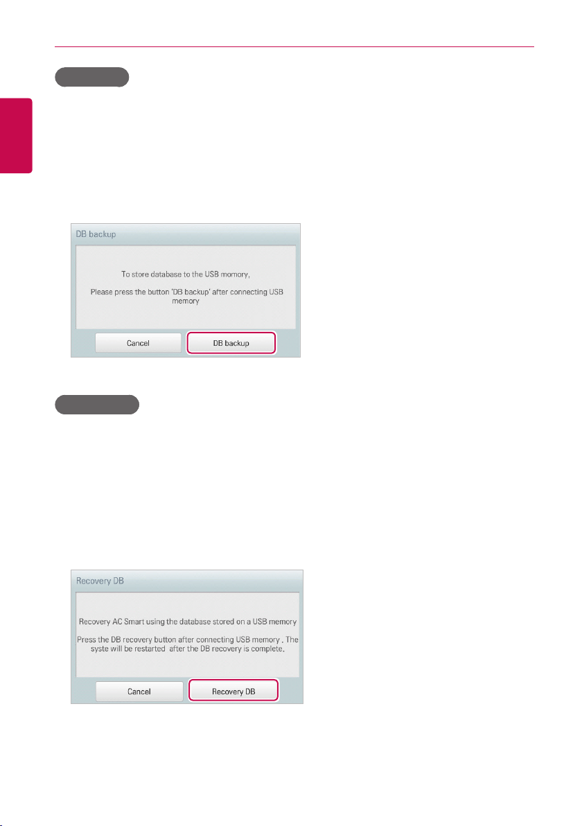
144
ENGLISH
USING THE PROGRAM
DB backup
You can backup the database stored in the system to USB memory as follows.
1. Connect the USB memory to ACS IV Controller.
2. In the main menu, click(touch) the [Environment] menu icon.
3. In the Settings list, click(touch) Advance Setting.
4. In the detailed settings list, click(touch) DB backup.
5. When the DB Backup window appears, click(touch) the [DB backup] button.
Recovery DB
You can use the database stored on USB memory to restore the system database.
1. Connect the USB memory stick to ACS IV Controller.
2. In the main menu, click(touch) the [Environment] menu icon.
3. In the Settings list, click(touch) Advance Setting.
4. In the detailed settings list, click(touch) Recovery DB.
5. When the DB Recovery window appears, click(touch) the [Recovery DB] button.
• When the DB recovery has been completed, the program restarts.
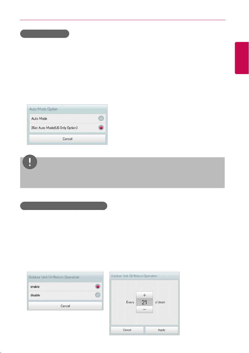
145
ENGLISH
USING THE PROGRAM
Auto Mode Option
You can configure the Auto Mode Option as follows.
1. In the main menu, click(touch) the [Environment] menu icon.
2. In the Settings list, click(touch) Advance Setting.
3. In the detailed settings list, click(touch) Auto Mode Option.
4. Click(Touch) an auto mode you want.
• Auto Mode: ACS IV Controller’s IDU Auto Mode (Auto Change Over, Setback)
• 2Set Auto Mode: IDU 2Set Auto Mode. U.S Only Option
NOTES
In case of ACP BACnet and AC Smart BACnet, BACnet Object Instance Number vary
depending on the
[Auto Mode Option]
setting. Please refer to the instruction manual for details.
Outdoor Unit Oil-Return Operation
You can configure Outdoor Unit Oil-Return Operation as follows.
1. In the main menu, click(touch) the [Environment] menu icon.
2. In the Settings list, click(touch) Advance Setting.
3. In the detailed settings list, click(touch) Outdoor Unit Oil-Return Operation.
4. Click(Touch) the desired Operation.
• When selecting ‘enable’, in the Time Setting window, click the desired time.
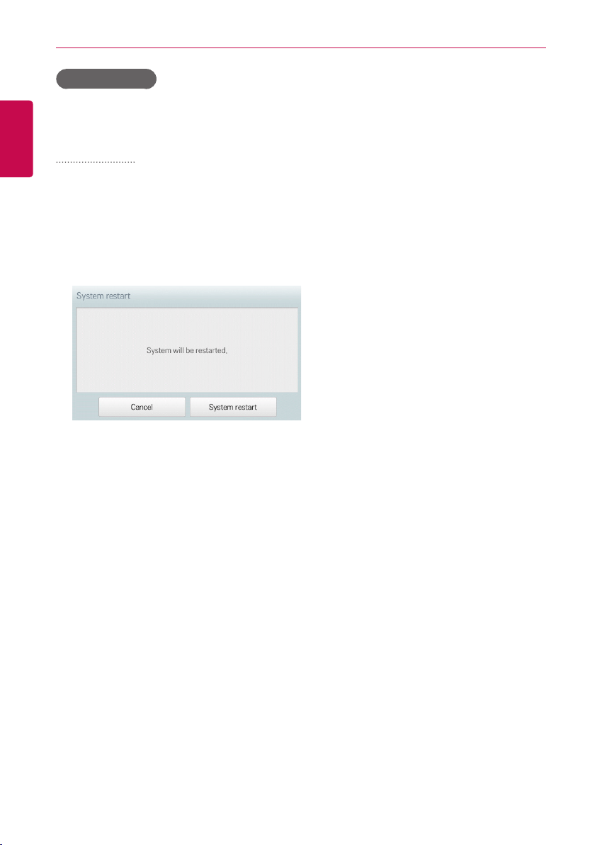
146
ENGLISH
USING THE PROGRAM
System Restart
Remotely restart the system.
System Restart
The method to restart the system remotely is as follows.
1. In the main menu, click(touch) the [Environment] menu icon.
2. In the Settings list, click(touch) Advance Setting.
3. Click(touch) the System Restart in the detailed setting list.
4. To restart the system, click(touch) the [System Restart] button.
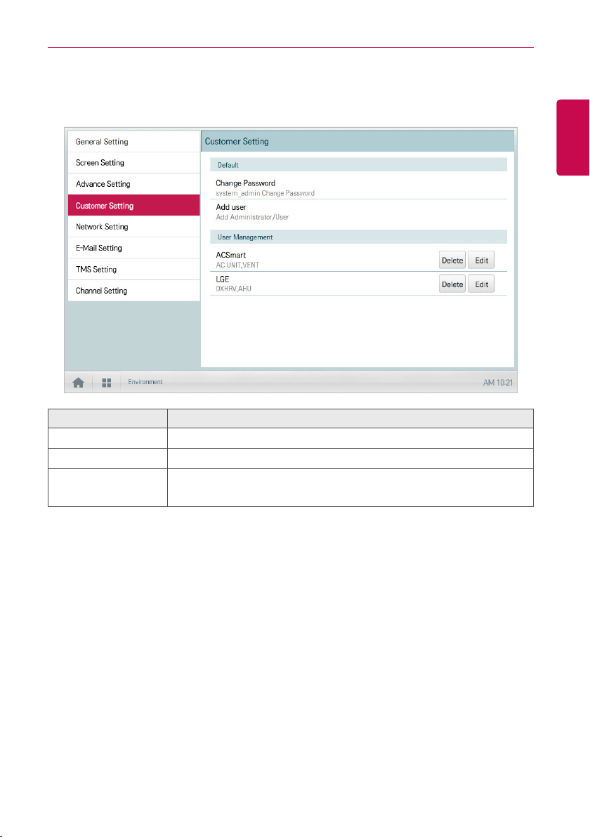
147
ENGLISH
USING THE PROGRAM
Customer Setting
Only the administrator account can change user environments.
Item Description
Change Password Only the administrator account can change the password.
Add user Add up to 30 new system users.
User Management
y [Delete] Button: Deletes a user.
y [Edit] Button: Changes user information.
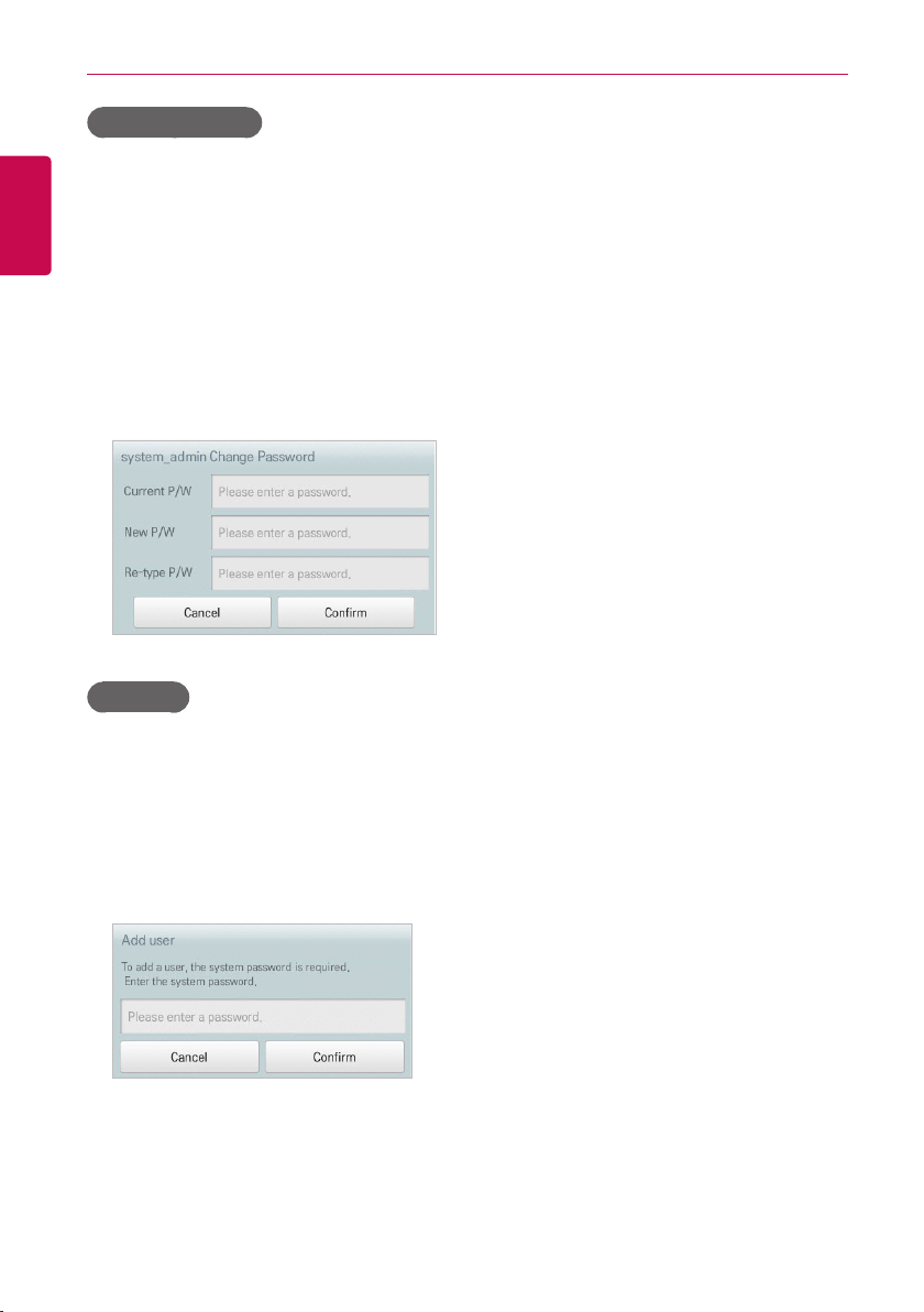
148
ENGLISH
USING THE PROGRAM
Change Password
The system_admin account password can be changed as follows.
1. In the main menu, click(touch) the [Environment] menu icon.
2. In the Settings list, click(touch) Customer Setting.
3. In the detailed settings list, click(touch) Change Password.
4. After entering the current and new passwords, click(touch) the [Confirm] button.
• Current P/W: Enter the current password.
• New P/W: Enter the new password for system_admin..
• Re-type P/W: Enter the new password to confirm that the new password has been entered
correctly.
Add user
You can add a user as follows.
1. In the main menu, click(touch) the [Environment] menu icon.
2. In the Settings list, click(touch) Customer Setting.
3. In the detailed settings list, click(touch) Add User.
4. When the system password input window appears, enter the password and click(touch) the
[Confirm] button.
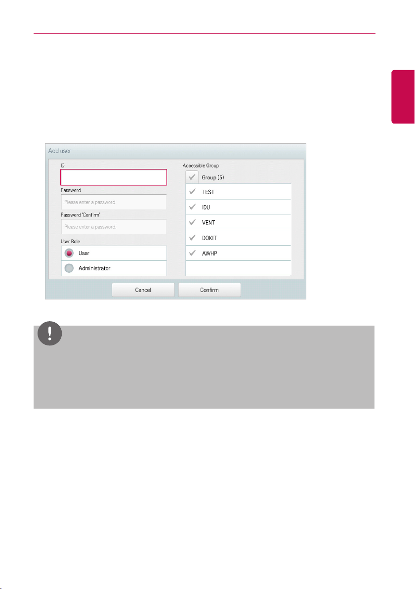
149
ENGLISH
USING THE PROGRAM
5. When the Add a New User window appears, enter the user information and click(touch) the
[Confirm] button.
• ID: Enter the user's ID for the email server.
• Password: Enter the login password.
• Password 'Confirm': Re-enter the password.
• User Role: Select the user permission you want
• Accessible Group: Select a controllable device group
NOTES
Use is limited depending on the user.
y
General user menu: Control/Monitor, Schedule, Statistics for assigned Groups/Units
y
Administrator menu: Control/Monitor, Schedule, AutoLogic, Statistics, Report, Installing for all
Groups/Units
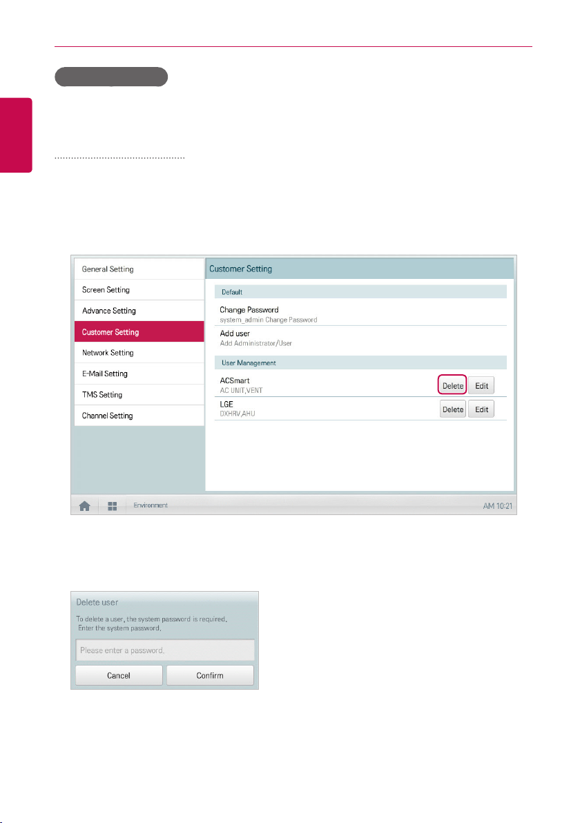
150
ENGLISH
USING THE PROGRAM
User Management
The following explains how to delete a registered user or edit user information.
Deleting User Information
You can delete a registered user's information as follows.
1. In the main menu, click(touch) the [Environment] menu icon.
2. In the Settings list, click(touch) Customer Setting.
3. In the user list, click(touch) the [Delete] button for the user information you want to delete.
4. When the system password input window appears, enter the password and click(touch) the
[Confirm] button.
• The user information is deleted.
5. To complete user delete, click(touch) the [Confirm] button.
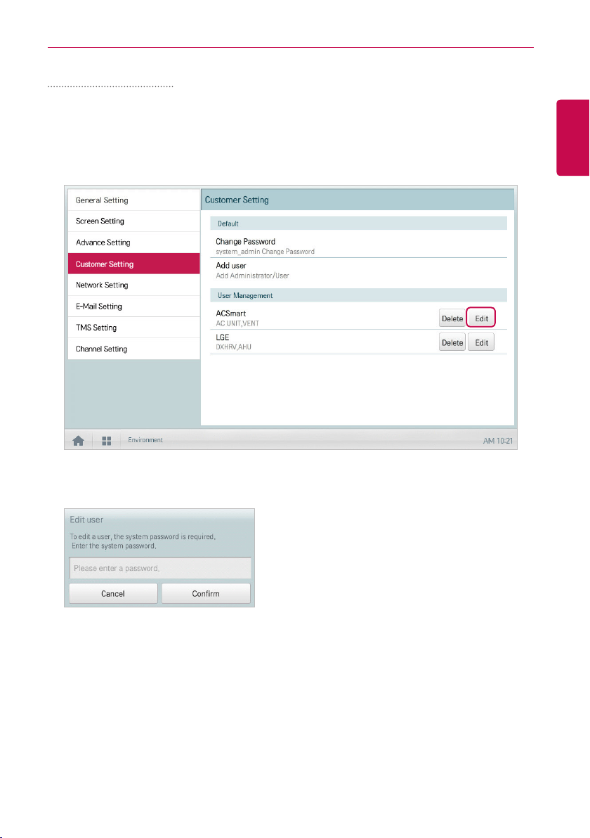
151
ENGLISH
USING THE PROGRAM
Editing User Information
You can edit a registered user's information as follows.
1. In the main menu, click(touch) the [Environment] menu icon.
2. In the Settings list, click(touch) Customer Setting.
3. In the user list, click(touch) the [Edit] button for the user information you want to edit.
4. When the system password input window appears, enter the password, click(touch) the
[Confirm] button.
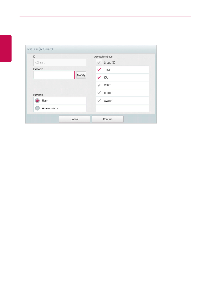
152
ENGLISH
USING THE PROGRAM
5. When the Edit User window appears, enter the user information and click(touch) the [Confirm]
button.
• The updated user information is applied.
6. To complete user edit, click(touch) the [Confirm] button.
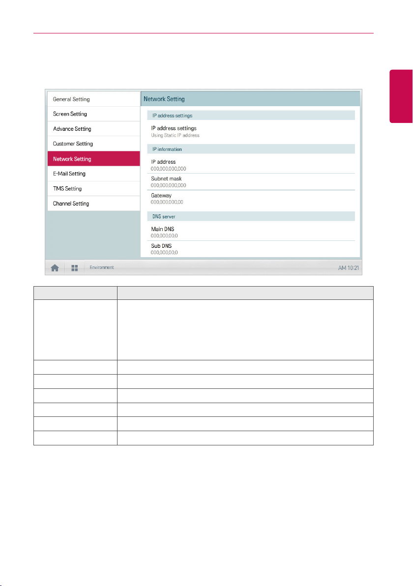
153
ENGLISH
USING THE PROGRAM
Network Setting (ACP BACnet, AC Smart IV, AC Smart BACnet Only)
The following explains how to configure the network environment.
Item Description
IP address settings
Select IP address allocation type.
y Get the IP address using DHCP: IP address is allocated by the
network automatically.
y Using Static IP address: Get IP address from the network
administrator and type it manually.
IP address Enter IP address
Subnet mask Enter the subnet mask information for the IP address.
Gateway Enter IP address of gateway.
Main DNS Enter the IP address of main DNS server.
Sub DNS Enter the IP address of secondary DNS server.
HTTP Port setting Input Web access Port (between 1 and 65535, default: 80)
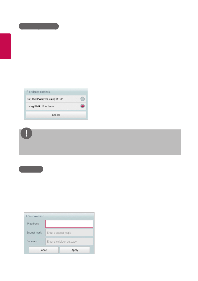
154
ENGLISH
USING THE PROGRAM
IP address settings
You can select the IP address allocation as follows.
1. In the main menu, click(touch) the [Environment] menu icon.
2. In the Settings list, click(touch) Network Setting.
3. In the detailed settings list, click(touch) IP address settings.
4. Click(Touch) an IP address allocation type you want.
• Get the IP address using DHCP: IP address is allocated by the network automatically
• Using Static IP address: Get IP address from the network administrator and enter it
manually
NOTES
IP address/Subnet mask/Gateway is activated when IP address allocation type is Using Static
IP address.
IP address
You can enter the IP address as follows.
1. In the main menu, click(touch) the [Environment] menu icon.
2. In the Settings list, click(touch) Network Setting.
3. In the detailed settings list, click(touch) IP address.
4. When the IP information window appears, click(touch) the [Apply] button.
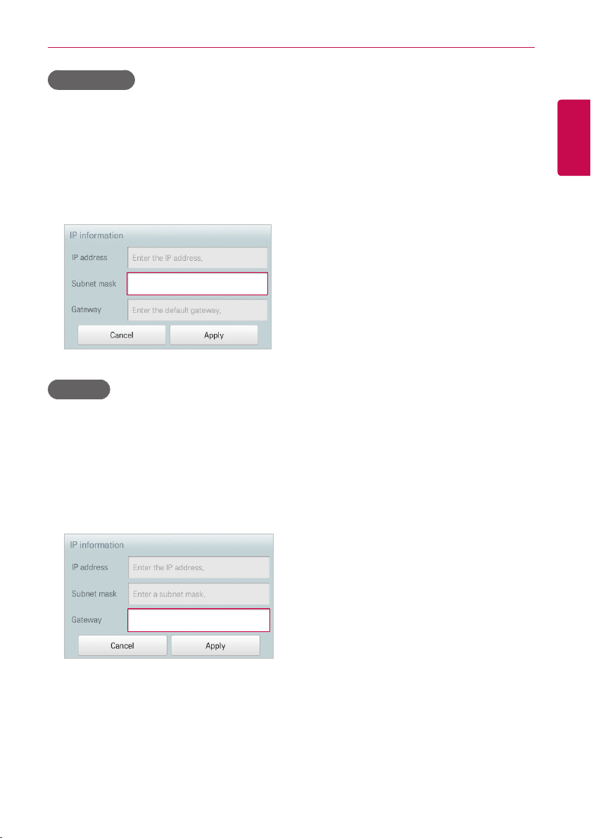
155
ENGLISH
USING THE PROGRAM
Subnet mask
You can enter the subnet mask information for an IP address as follows.
1. In the main menu, click(touch) the [Environment] menu icon.
2. In the Settings list, click(touch) Network Setting.
3. In the detailed settings list, click(touch) Subnet mask.
4. When the IP Information window appears, enter the subnet mask information, click(touch) the
[Apply] button.
Gateway
You can enter the IP address of a gateway as follows.
1. In the main menu, click(touch) the [Environment] menu icon.
2. In the Settings list, click(touch) Network Setting.
3. In the detailed settings list, click(touch) Gateway.
4. When the IP Information window appears, enter the IP address of the gateway and click(touch)
the [Apply] button.
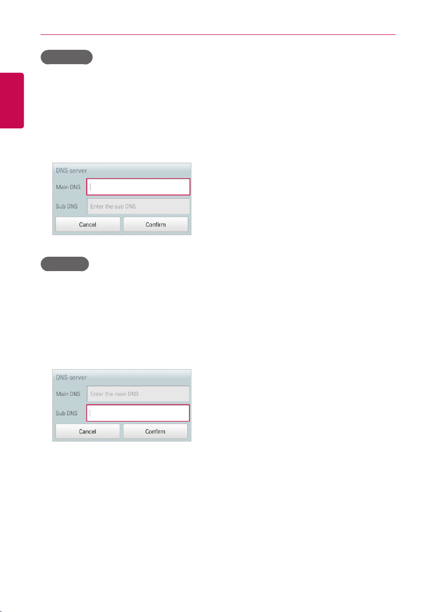
156
ENGLISH
USING THE PROGRAM
Main DNS
You can enter the IP address of a main DNS server as follows.
1. In the main menu, click(touch) the [Environment] menu icon.
2. In the Settings list, click(touch) Network Setting.
3. In the detailed settings list, click(touch) Main DNS.
4. When the DNS Server window appears, enter the IP address of the main DNS server and
click(touch) the [Confirm] button.
Sub DNS
You can enter the IP address of a secondary DNS server as follows.
1. In the main menu, click(touch) the [Environment] menu icon.
2. In the Settings list, click(touch) Network Setting.
3. In the detailed settings list, click(touch) Sub DNS.
4. When the DNS Server window appears, enter the IP address of the secondary DNS server and
click(touch) the [Confirm] button.
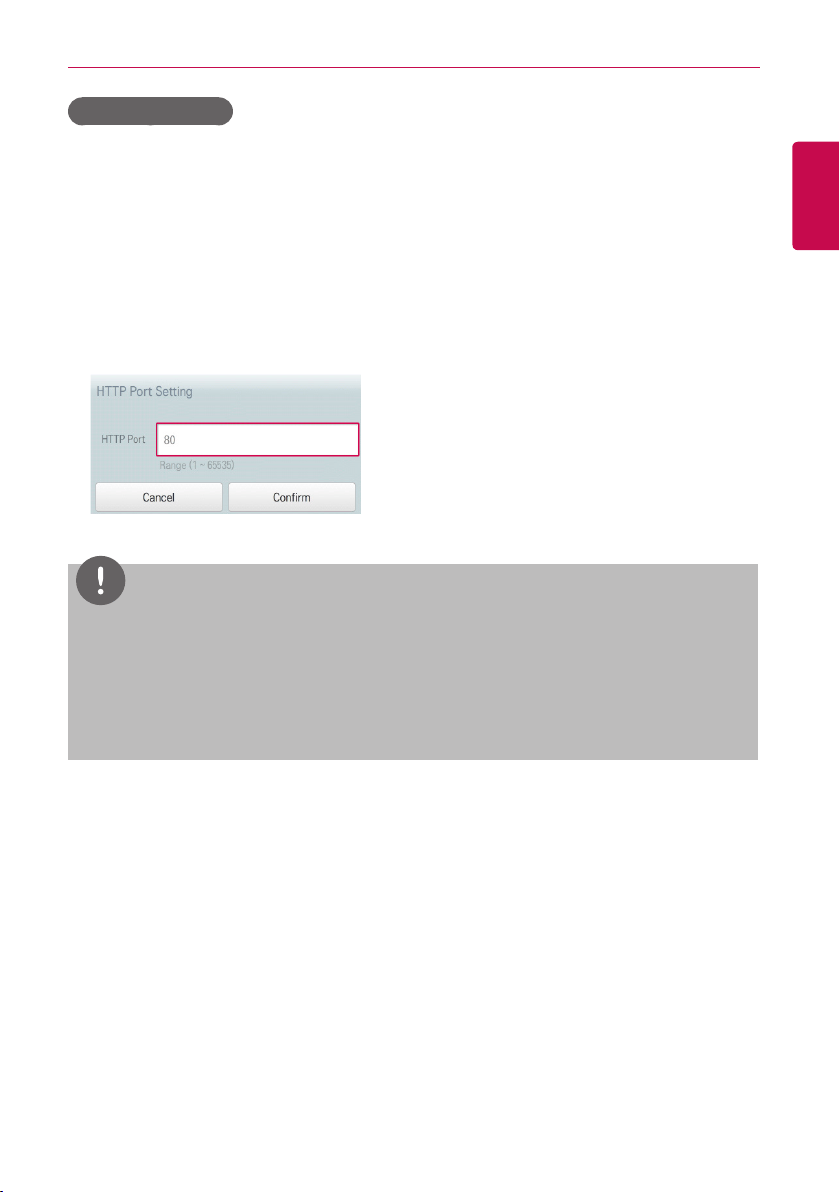
157
ENGLISH
USING THE PROGRAM
HTTP Port setting
If certain ports are restricted by network manager, you will not be able to access the web for ACS IV
Controller.
You can set the available HTTP port as follows:
1. In the main menu, click(touch) the [Environment] menu icon.
2. In the Settings list, click(touch) Network Setting.
3. In the detailed settings list, click(touch) HTTP Port setting.
4. When HTTP Port setting window is displayed, input HTTP Port boundary (1~65535) and
click(touch) the [Confirm] button.
NOTES
After setting HTTP Port, the web access method is http://IP address:Port. when a port other
than 80 is used.
y
If IP address is 123.123.123.123 and Port is set to 4321, the access address is
http://123.123.123.123:4321.
y
Be careful when changing port numbers. Another application may be using that port.
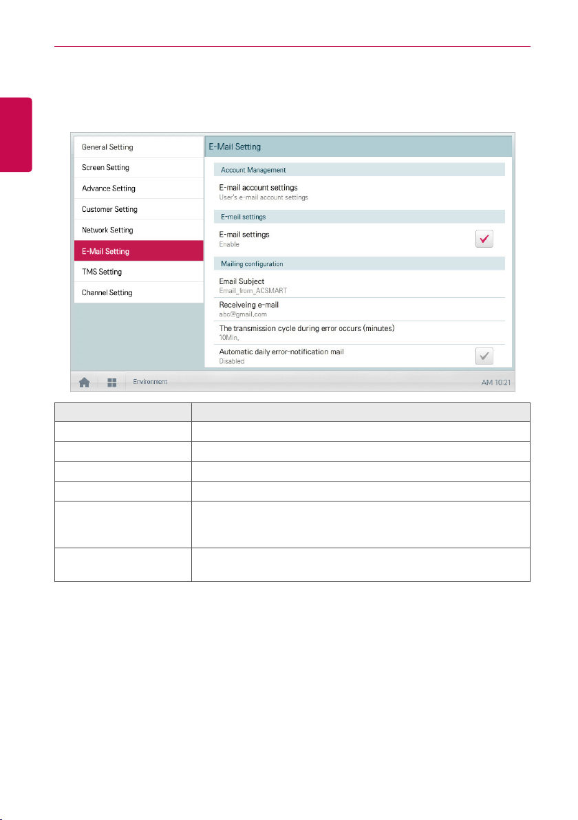
158
ENGLISH
USING THE PROGRAM
E-Mail Setting
When the administrator is not present, ACS IV Controller emails any error information to the
administrator for reviewing. The following explains how to configure the email.
Item Description
E-mail account settings Configuring user email account.
E-mail settings Select whether to use the email.
Email Subject Type an email subject line when sending an email.
Receiving e-mail Register the email address of the receiver who will receive the email.
The transmission cycle
during error occurs
(minutes)
Set the transmission repeat cycle to send an email when an error
occurs.
Automatic daily
error-notification mail
Configure an email to be sent at 00:00 every day, even if there are no
errors to report.
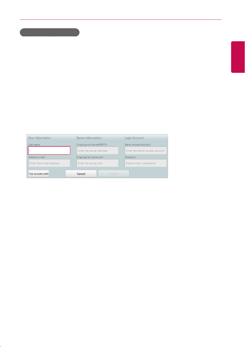
159
ENGLISH
USING THE PROGRAM
E-mail account settings
You can configure the user's email account.
1. In the main menu, click(touch) the [Environment] menu icon.
2. In the Settings list, click(touch) E-Mail Setting.
3. In the detailed settings list, click(touch) E-mail account settings.
4. Type the email account information.
• User name: Enter the email user's name.
• Address e-mail: Enter the user's e-mail address.
• Outgoing mail server(SMTP): Enter the address of the mail server.
• Outgoing mail server port: Enter the port of the mail server.
• Server Access Account: Enter the server connection account.
• Password: Enter the password to log onto the mail server.
5. Click(Touch) [Test account setting] to check if the configured account is correct.
6. When the Account Configuration Completion window appears, click(touch) the [Confirm] button.
7. To complete the email account configuration, click(touch) the [Confirm] button.
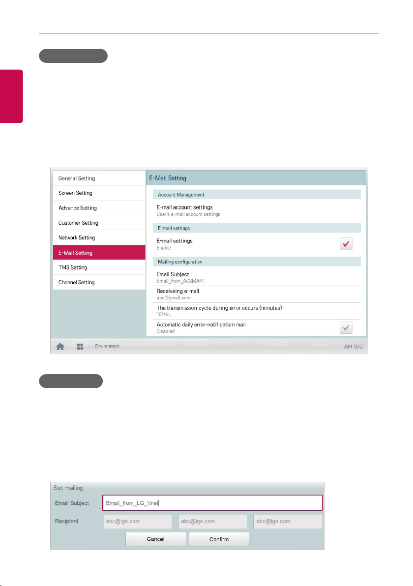
160
ENGLISH
USING THE PROGRAM
E-mail settings
You can select whether to use the email function as follows.
1. In the main menu, click(touch) the [Environment] menu icon.
2. In the Settings list, click(touch) E-Mail Setting.
3. In the detailed settings list, click(touch) E-mail settings.
• If Enable is selected, the check box turns red and the Email Subject, Receiving e-mail,
The transmission cycle during error occurs (minutes), and Automatic daily
errornotification mail are enabled.
Email Subject
You can type an email subject line as follows. This will be used for every email sent.
1. In the main menu, click(touch) the [Environment] menu icon.
2. In the Settings list, click(touch) E-Mail Setting.
3. In the detailed settings list, click(touch) Email Subject.
4. When the Configuring Email window appears, enter the email title and click(touch) the [Confirm]
button.
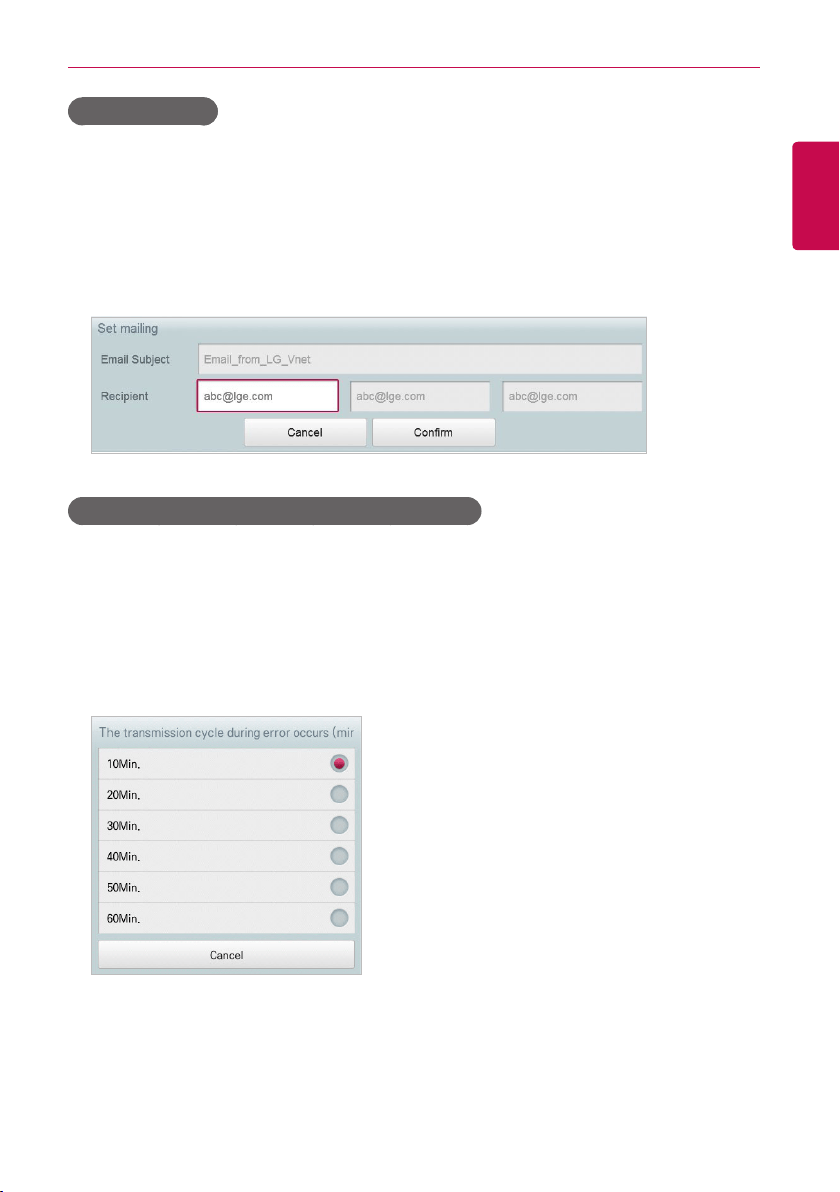
161
ENGLISH
USING THE PROGRAM
Recipient e-mail
You can register the email address of up to three email receivers as follows.
1. In the main menu, click(touch) the [Environment] menu icon.
2. In the Settings list, click(touch) E-Mail Setting.
3. In the detailed settings list, click(touch) Recipient e-mail.
4. When the Configuring Email window appears, enter the email address of the email receiver and
click(touch) the [Confirm] button.
The transmission cycle after error occurs (minutes)
You can set the schedule for when to send an email (after an error occurs) from 10 minutes to within
one hour as follows.
1. In the main menu, click(touch) the [Environment] menu icon.
2. In the Settings list, click(touch) E-Mail Setting.
3. In the detailed settings list, click(touch) The transmission cycle during error occurs (minutes).
4. When the Select an Email Schedule window appears, click(touch) a sending schedule you want.

162
ENGLISH
USING THE PROGRAM
NOTES
E-mails will continue to generate at the time intervals until the fault or error is resolved. It is
suggested that the least amount of time (a longer time interval) be chosen so recipients are not
overwhelmed with frequent emails.
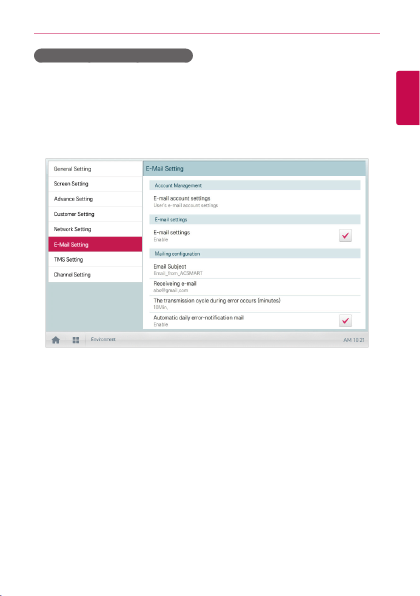
163
ENGLISH
USING THE PROGRAM
Automatic daily error-notification mail
You can configure an email to be sent automatically once per day, even if there are no error, as
follows.
1. In the main menu, click(touch) the [Environment] menu icon.
2. In the Settings list, click(touch) E-Mail Setting.
3. In the detailed settings list, click(touch) Automatic daily error-notification mail.
• Enable is selected, the check box turns red.
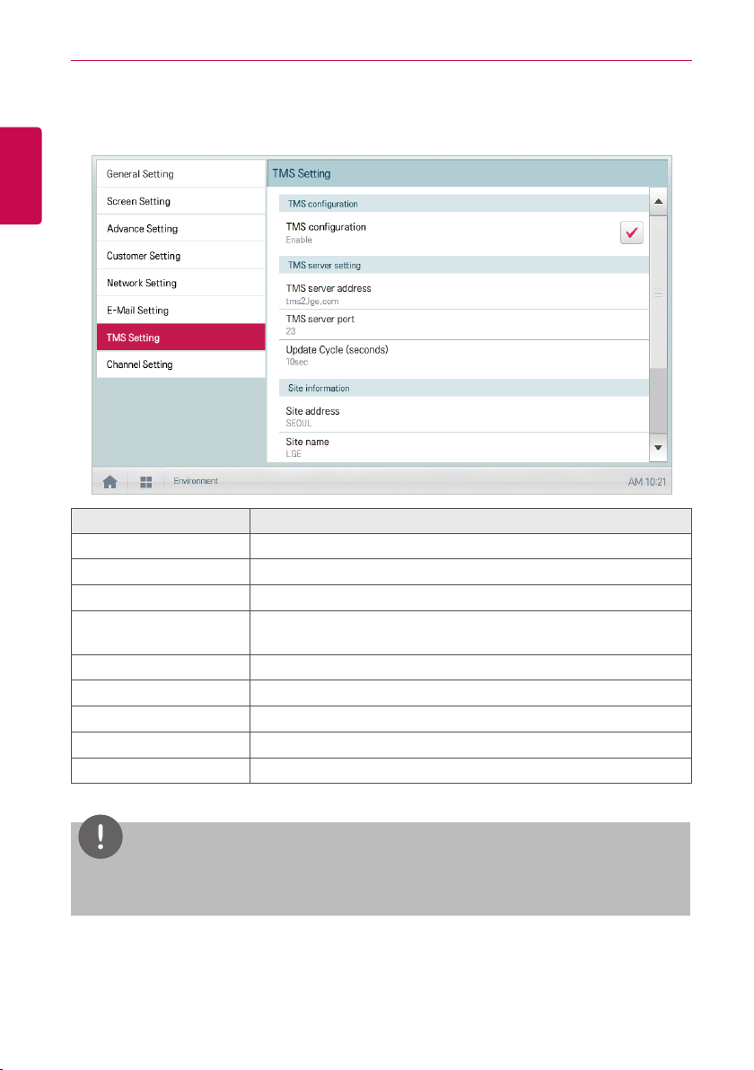
164
ENGLISH
USING THE PROGRAM
TMS Setting
The following explains how to configure the remote monitoring and control system.
Item Description
TMS configuration Select whether to use a remote control service.
TMS server address Configure the remote control service server address.
TMS server port Configure the remote control service port.
Update Cycle (seconds)
Configures the remote control service update cycle
(in seconds).
Site address Enter an address for the remote site.
Site name Enter the site name.
Site code Click(Touch) the [Request Site Code] button to enter the site code.
Admin Name Enter the name of the site manager.
Admin Contact Enter the site manager's phone number.
NOTES
TMS is not available in the US market at this time.
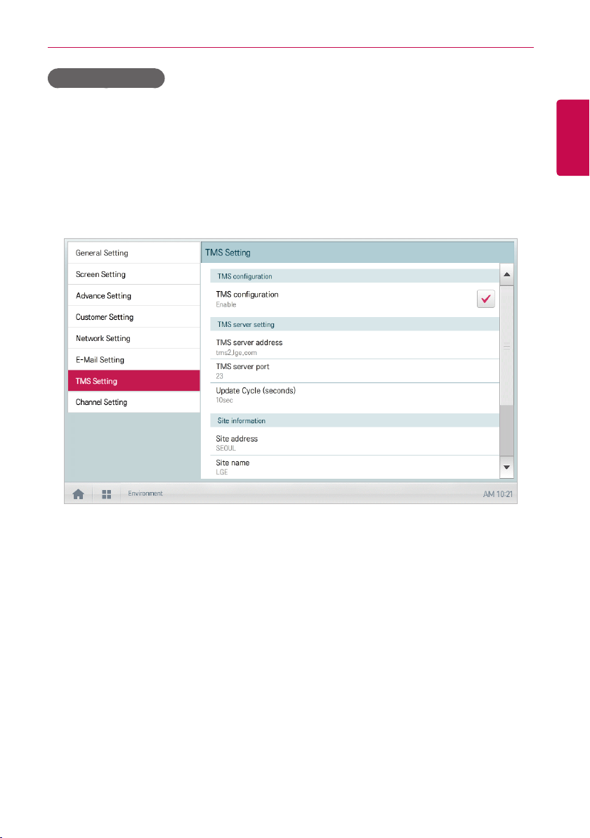
165
ENGLISH
USING THE PROGRAM
TMS configuration
You can select whether to use the remote control service as follows.
1. In the main menu, click(touch) the [Environment] menu icon.
2. In the Settings list, click(touch) TMS Setting.
3. In the detailed settings list, click(touch) TMS configuration.
• If Enable is selected, the check box turns red and TMS server address, TMS server port,
Update Cycle (seconds), Site address, Site name, Site code, Admin Name, and Admin
Contact are enabled.
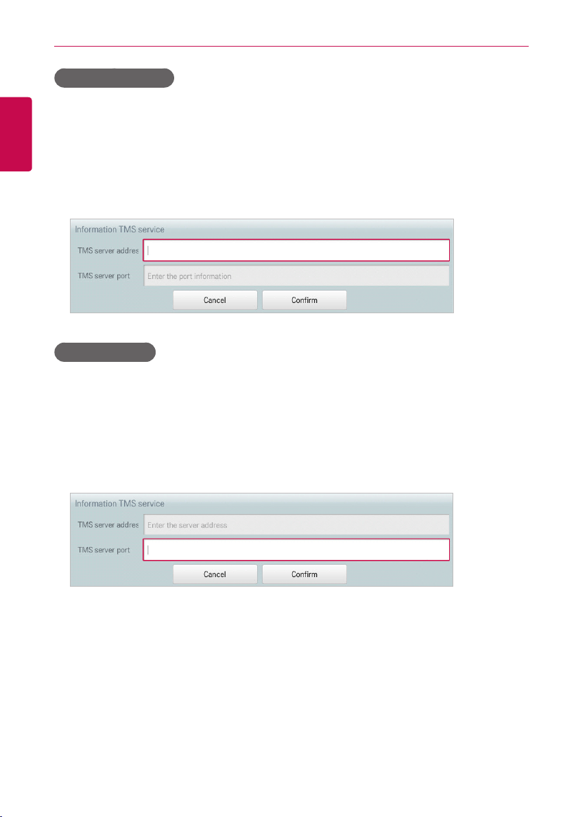
166
ENGLISH
USING THE PROGRAM
TMS server address
You can configure the server address of the remote control service as follows.
1. In the main menu, click(touch) the [Environment] menu icon.
2. In the Settings list, click(touch) TMS Setting.
3. In the detailed settings list, click(touch) TMS server address.
4. When the Remote Service Information window appears, enter the service server address and
click(touch) the [Confirm] button.
TMS server port
You can configure the server port of the remote control service as follows.
1. In the main menu, click(touch) the [Environment] menu icon.
2. In the Settings list, click(touch) TMS Setting.
3. In the detailed settings list, click(touch) TMS Server Port.
4. When the Remote Service Information window appears, enter the service server port and
click(touch) the [Confirm] button.
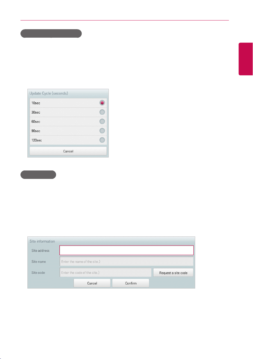
167
ENGLISH
USING THE PROGRAM
Update Cycle (seconds)
You can configure the update cycle of the remote control service information as follows.
1. In the main menu, click(touch) the [Environment] menu icon.
2. In the Settings list, click(touch) TMS Setting.
3. In the detailed settings list, click(touch) Update Cycle (seconds).
4. When the Configuring Update Cycle window appears, click(touch) an update cycle you want.
Site address
You can type the address of the site where ACS IV Controller is installed.
1. In the main menu, click(touch) the [Environment] menu icon.
2. In the Settings list, click(touch) TMS Setting.
3. In the detailed settings list, click(touch) Site address.
4. When the Configuring Site Information window appears, enter the site address and click(touch)
the [Confirm] button.
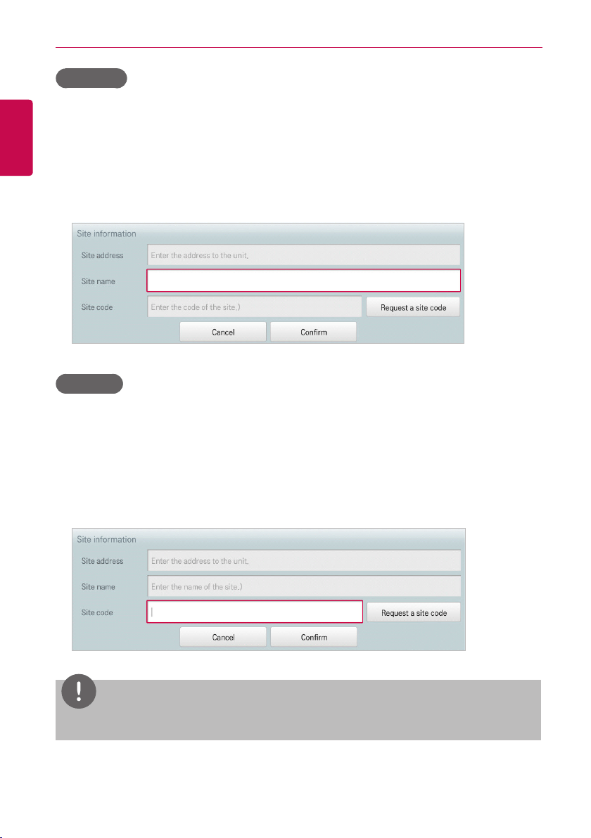
168
ENGLISH
USING THE PROGRAM
Site name
You can type the name of the site where ACS IV Controller is installed.
1. In the main menu, click(touch) the [Environment] menu icon.
2. In the Settings list, click(touch) TMS Setting.
3. In the detailed settings list, click(touch) Site name.
4. When the Configuring Site Information window appears, enter the site name and click(touch) the
[Confirm] button.
Site code
You can allocate a code for site management as follows.
1. In the main menu, click(touch) the [Environment] menu icon.
2. In the Settings list, click(touch) TMS Setting.
3. In the detailed settings list, click(touch) Site code.
4. When the Configuring Site Information window appears, click(touch) the [Request a site code]
button to enter the site code and click(touch) the [Confirm] button.
NOTES
You must enter the site address details before you can request the site code.
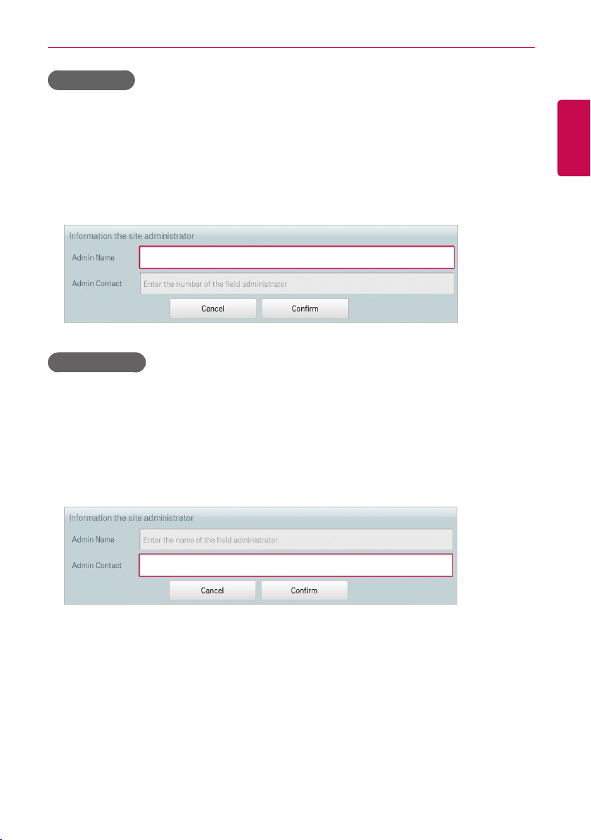
169
ENGLISH
USING THE PROGRAM
Admin Name
You can type the site manager's name as follows.
1. In the main menu, click(touch) the [Environment] menu icon.
2. In the Settings list, click(touch) TMS Setting.
3. In the detailed settings list, click(touch) Admin Name.
4. When the Configuring Site Manager Information window appears, enter the site manager's name
and click(touch) the [Confirm] button.
Admin Contact
You can type the site manager's phone number as follows.
1. In the main menu, click(touch) the [Environment] menu icon.
2. In the Settings list, click(touch) TMS Setting.
3. In the detailed settings list, click(touch) Admin Contact.
4. When the Configuring Site Manager Information window appears, enter the site manager's phone
number and click(touch) the [Confirm] button.
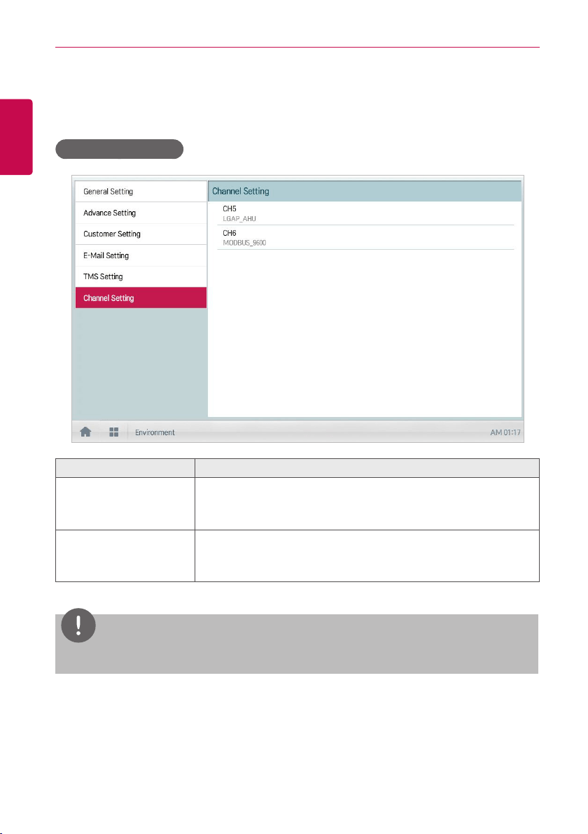
170
ENGLISH
USING THE PROGRAM
Channel Setting
The following explains channel setting of ACS IV Controller.
ACP IV, ACP BACnet
Item Description
CH5
y LGAP_AHU: AHU(Normal, Fresh Air, Heat Recovery) connection.
y MODBUS_9600, MODBUS_19200: AHU(Modular Fresh Air,
Modular Heat Recovery, DOAS), Exp.I/O, Chiller connection.
CH6
y DEMAND: Demand Controller connection
y MODBUS_9600, MODBUS_19200: AHU(Modular Fresh Air,
Modular Heat Recovery, DOAS), Exp.I/O, Chiller connection.
NOTES
The default MODBUS communication setting is MODBUS_9600.
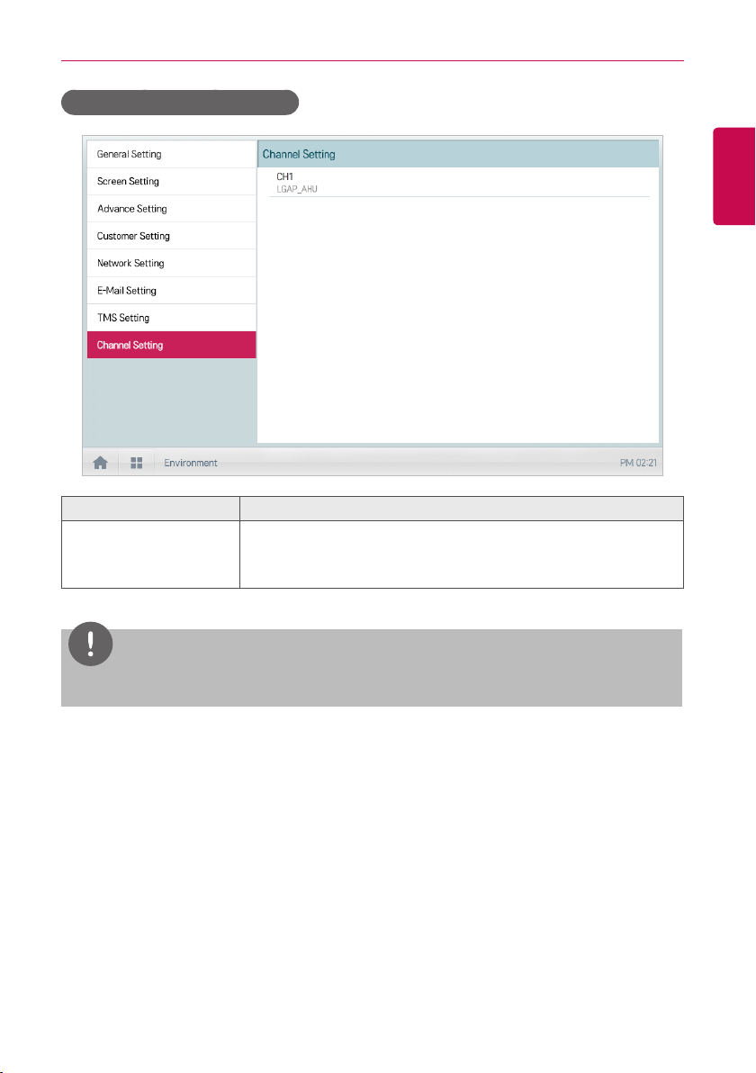
171
ENGLISH
USING THE PROGRAM
AC Smart IV, AC Smart BACnet
Item Description
CH1
y LGAP_AHU: AHU(Normal, Fresh Air, Heat Recovery) connection.
y MODBUS_9600, MODBUS_19200: AHU(Modular Fresh Air,
Modular Heat Recovery, DOAS), Exp.I/O, Chiller connection.
NOTES
The default MODBUS communication setting is MODBUS_9600.
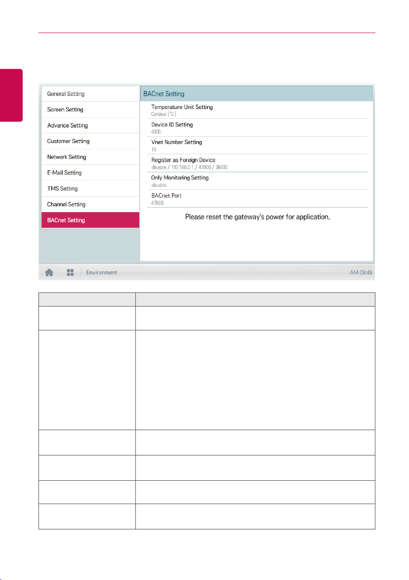
172
ENGLISH
USING THE PROGRAM
BACnet Setting (ACP BACnet, AC Smart BACnet Only)
The following explains BACnet setting of ACS IV Controller.
Item Description
Temperature Unit
Setting
To set the temperature unit communicating with BMS.
Device ID Setting
To designate the Device Instance Number, Device ID must be set.
Default Device ID is 9000, Device Instance Number is designated as
below.
y Indoor unit : Device ID
y ERV:DeviceID+1
y AHU:DeviceID+2
y Outdoorunitcycleinformation:DeviceID+3
y AWHP:DeviceID+4
y General:DeviceID+5
Vnet Number Setting
To use Modbus TCP function of ACP BACnet, Vnet Number must be set.
Set Vnet Number is used to Slave ID Address of Modbus TCP.
Register as Foreign
Device
To register Foreign Device.
For more information, please consult with the experts of BMS.
Only Monitoring Setting
When set to Enable the BMS has Read Only permission on this
device. Uncheck if BMS is required to have Read & Write permission.
BACnet Port
To change the BACnet IP port. Default port is 47808.
For more information, please consult with the experts of BMS.

ver. 1.0.1


