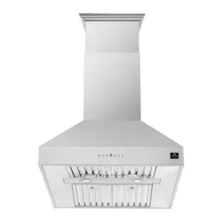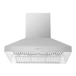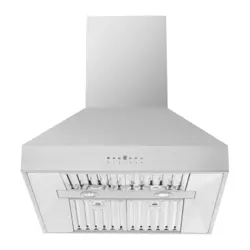
ECVI4262AS
User Manual
Range Hood
EN 2
CONTENTS
1. SAFETY INSTRUCTIONS-------------------------------------------------------------------
2. ELECTRICAL REQUIREMENTS------------------------------------------------------------
3. PARTS SUPPLIED----------------------------------------------------------------------------
4. OPTIONAL ACCESSORIES---------------------------------------------------------------
5. INSTALLING THE HOOD ------------------------------------------------------------------
6. OPERATION-----------------------------------------------------------------------------------
7. SPECIAL FUNCTION-----------------------------------------------------------------------
8. CLEANING AND MAINTENANCE------------------------------------------------------
9. TECHNICAL DATA--------------------------------------------------------------------------
10.TROUBLE SHOOTING-------------------------------------------------------------------
11.ENVIRONMENTAL PROTECTION----------------------------------------------------
12.WARRANTY INFORMATION-----------------------------------------------------------
2
5
6
6
7
14
14
15
16
16
16
17
SAFETY INSTRUCTIONS
Do not attempt to install or operate this appliance until you
have read the safety instructions in this manual. Safety items
throughout this manual are labelled with a Danger, Warning,
or Caution based on the risk type.
DEFINITIONS
This is the safety alert symbol. It is used to alert you to potential personal injury
hazards. Obey all safety messages that follow this symbol to avoid possible injury or
death.
DANGER:
DANGER indicates an imminently hazardous situation which, if not avoided,
will result in death or serious injury.
WARNING:
DANGER indicates an imminently hazardous situation which, if not avoided,
will result in death or serious injury.
2 ENGLISH
CAUTION:
CAUTION indicates a potentially hazardous situation which, if not avoided, could result
in minor or moderate injury.
CHILD SAFETY
Packing materials:
Packing cartons covered with rugs, bedspreads,plastic sheets, or stretch wrap may
become airtight chambers and can quickly cause suffocation.
Removetheprotectivefilm coveringtheappliance before putting it into operation.
Destroy or recycle the appliance's carton, plastic bags, and any other exterior
wrapping material immediately after the product is unpacked. Children should never
play with these items. Danger of suffocation!
IMPORTANT
CAREFULLY BEFORE INSTALLATION AND USE.
INSTALLATION MUST COMPLY WITH ALL LOCAL CODES.
IMPORTANT: Save these instructions for the Local Electrical Inspector's
use.
INSTALLER: Please leave these instructions with this appliance for the
owner.
OWNER: Please retain these instructions for future reference.
DANGER:
Always switch off the electricity supply at the mains during installation
and maintenance.
WARNING:
To reduce the risk of fire, electric shock, or injury to persons, observe the following:
FOR RESIDENTIAL USE ONLY
Use this appliance only in the manner intended by the manufacturer. If you have
questions, contact the manufacturer.
Installation work and electrical wiring must be done by qualified person(s )in
accordance With all applicable codes & standards, including fire-rated construction.
Sufficient air is needed for proper combustion and exhausting of gases
through the flue (chimney) of fuel burning equipment to prevent back-drafting. Follow the
heating equipment manufacturers guideline and safety standards such as those published
by the National Fire Protection Association (NFPA), the American Society for Heating,
Refrigeration and Air Conditioning Engineers (ASHRAE), and the local code authorities.
When cutting or drilling into wall or ceiling, do not damage electrical wiring and other hidden
utilities (e.g. gas pipes).
Ducted systems must always be vented to the outdoors. always be vented to the outdoors.
3 ENGLISH
WARNING:
Before servicing or cleaning the unit, switch power off at service panel and lock service
panel disconnecting means to prevent power from being switched on accidentally.
When the service disconnecting means cannot be locked, securely fasten a prominent
warning device, such as a tag,to the service panel.
4 ENGLISH
CAUTION:
For general ventilating use only. DO NOT use to exhaust hazardous or explosive
materials or vapors.
CAUTION:
To reduce risk of fire and to properly exhaust air, be sure to duct air outside - do not vent
exhaust air into spaces within walls, ceilings, attics, crawl spaces, or garages.
WARNING:
To reduce the risk of fire, use only metal duct work. Install this hood in accordance with
all requirements specified.
WARNING:
To reduce the risk of fire or electric shock, do not use this hood with any external solid
state speed control device.
WARNING:
Never leave surface units unattended at high settings. Boilovers cause smoking and
greasy spillovers that may ignite. Heat oils slowly on low or medium settings.
Always turn hood on when cooking over high heat
To reduce the risk of a cooker top grease fire:
WARNING:
Use proper pan size. Always use cookware appropriate for the size of the surface
element.
Do not use the range hood without the grease filters, or if the filters are excessively
greasy.
WARNING:
Smother flames with a close-fitting lid,cookie sheet, or other metal tray, then turn
off the gas burner or the electric element. Be careful to prevent burns. If the flames
do not go out immediately, evacuate and call the fire department.
Never pick up a flaming pan - you may be burned.
Do not use water, including wet dishcloths or towels - a violent steam explosion will result.
Use an extinguisher only if:
You know you have a class ABC extinguisher, and you already know how to operate it.
The fire is small and contained in the area where it started.
The fire department is being called.
You can fight the fire with your back to an exit.
To reduce the risk of injury to persons, in the event of a cooker top grease
fire, observe the following:
CAUTION:
Always leave safety grills and filters in place.
5 ENGLISH
ELECTRICAL REQUIREMENTS
IMPORTANT
It is the customer's responsibility:
to contact a qualified electrical installer.
to assure that the electrical installation is
adequate and in conformance with National
Electrical Code, ANSI/NFPA 70 - latest
edition*,or CSA Standards C22.1-94,
Canadian Electrical Code, Part 1 and C22.2
No.0-M91-latest edition**
and all local codes and ordinances.
If codes permit and a separate ground wire is
used, it is recommended that a qualified
electrician determines that the ground path is
adequate.
Do not ground to a gas pipe.
Check with a qualified electrician if you are not
sure range hood is properly grounded.
Do not have a fuse in the neutral or ground
circuit.
IMPORTANT
The range hood must be connected with
copper wire only.
The range hood should be connected directly
to the fused disconnect (or circuit breaker) box
through metal electrical conduit.
Wire sizes must conform to the requirements
of the National Electrical Code ANSI/NFPA
70 - latest edition”, or CSA Standards C22.1-
94, Canadian Electrical Code Part 1 and
C22.2 No.0-M91 - latest edition** and all local
codes and ordinances.
A U.L.- or C.S.A.-listed conduit connector
must be provided at each end of the power
supply conduit (at the range hood and at the
junction box).
Copies of the standards listed may be obtained
from:
* National Fire Protection Association Battery
march Park Quincy, Massachusetts 02269
* * CSA International 8501 East Pleasant Valley
Road Cleveland, Ohio 44131-5575
Power requirement:
120V-, 60Hz, 15 or 20A branch circuit.
Save installation instructions for electrical
inspector's use.
Observe all governing codes and
ordinances.
To Reduce The Risk Of Fire And Electric Shock,
Install This Rangehood Only With Integral Blowers
Manufactured by Chinabest Home Appliance Co.,
Ltd, Model CTH03-128D.
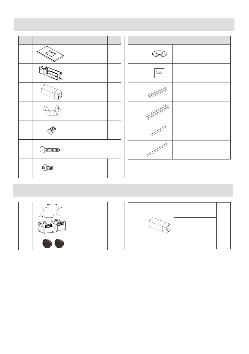
PARTS SUPPLIED
No. Part Qty.
1.
Range hood
1
2.
Upper chimney
+
Lower chimney
3.1
+
3.2
3.
Truss part
1
4.
Wire cover
1
1.
1
Long screws
ST6x70
4
6.
Recirculation kit
with screws
Elux PN:
EHRKT62AS
7.
5
Short screw
M4x10
6 ENGLISH
8.
2.
9.
Washer
8x16
4
1
1
Assembly
template
No. Part Qty.
8' extension chimney
Elux PN:EHI08X62AS
5.
3
Wire cap
OPTIONAL ACCESSORIES
10.
12.
11.
13.
Side supporting
bracket
Side sponge strip
2
2
2
2
Front and back
supporting bracket
Front and back
sponge strip
12' extension chimney
Elux PN:EHI12X62AS
14' extension chimney
Elux PN:EHI14X62AS
INSTALLING THE HOOD
Tools/Materials required
Duct tape
Wire nuts
Tape to mount template
6" rounded metal duct, length to suit
installation
Measuring tape
Pliers
Gloves to protect against sharp edges
Knife
Safety glasses
Electric drill
Strain relief
Spirit level
Phillips (Pozidrive) # 2 screwdriver + torx # 2
Wire cutter/stripper
Masking tape
Hammer
Saw, jig saw or reciprocating saw
7 ENGLISH
IMPORTANT
We recommend that three people carry
out the installation.
Preparation
The vent hood should be on site before
final framing and wall finishing. This will
help to accurately locate the duct work and
electrical service.
Installation will be easier if the vent hood is
installed before the cooktop and
countertop are installed.
Ductwork and wiring locations:
Determine the exact location of the vent
hood.
Plan the route for venting exhaust to the
outdoors.
Use the shortest and straightest duct route
possible.For satisfactory performance
duct run should not exceed 100'
equivalent length for any duct
configurations.
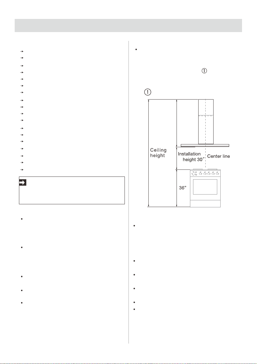
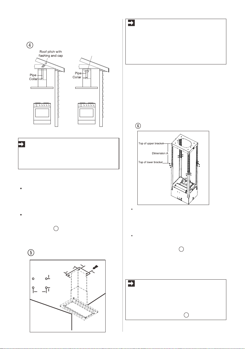
Refer to “ Ductwork installation
guidelines” chart to compute the
maximum permissible length for duct
runs to the outdoors (fig. ).
Ducting installation guidelines
For safety reasons when ducting outdoors
(not using a recirculation kit),ducting must
vent directly outdoors (not into an attic,
underneath the house, into the garage or
into any enclosed space).
Keep duct runs as short and straight as
possible.
Duct fittings (elbows and transitions) reduce
air flow efficiency.
Back to back elbow and “S” turns give very
poor delivery and are not recommended.
Use a suitable 6” round duct.
Flexible metal round ducts should only be
used when no other duct fitting exists. limit
use to short lengths and do not crush when
making corners.
Fig.
CAUTION
Remove the carton carefully.
Wear gloves to protect against sharp edges.
WARNING
Remove the protective film covering the
product before putting into operation.
8 ENGLISH
This vent hood is heavy. Adequate structure
and support must be provided in all types of
installations. Framing must support minimum
150 Ibs load.
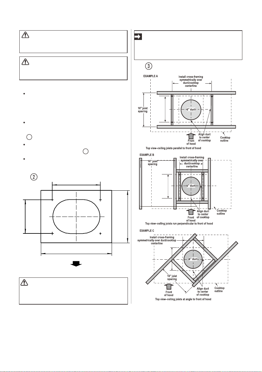
At the hood location, adequate bracing is
required to support the weight of the hood (fig.
2 )
Arrange cross framing in the ceiling to suit
the existing structure (fig. 3 )
Your ceiling joists will be like one of the
following examples.
NOTE: Do not cut the duct opening
shown on the template for the
recirculating installation.
IMPORTANT
Framing must be capable of supporting
150 lbs.
Fig.
Fig.
Ceiling Support Structures
Removing the packaging
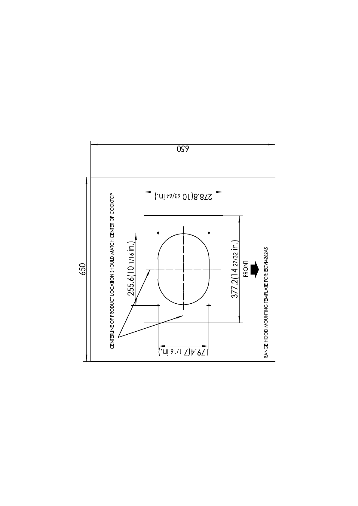
7 1/16"
10 1/16"
10 63/64"
14 27/32"
Front
10 1/16"
7 1/16"
10 1/16"
7 1/16"
10 1/16"
7 1/16"
9 ENGLISH
Examples of possible ducting or
air recirculation
IMPORTANT
This range hood is very heavy. Adequate
structure and support must be provided in
all types of installations.
Make sure that no cables or pipes will
become damaged (e.g. electric, gas, water;
test the areas in question with a cable
detector).
Using the template, mark and drill 4 holes
into the ceiling. Measure as displayed in
diagram (fig. ). The holes must be drilled
into a wood structure capable to support
150lbs load.
NOTE
1.The center of the template must match the
center of the cooktop and the edges must
be parallel to the sides of the cooktop.
2.Have a suitable ladder ready so that you
can easily reach up to the ceiling.
Unscrew 16 screws between the two sections
of the structure. Adjust extension of the hood
support structure (dimenssion A), as the final
height of the hood depends on this ,and
remember that with installation completed to
the hood must be at least 30" above the
cooktop.
1 With 8'/12'/14' extension chimney kit –
not supplied. Please call Electrolux at
1-800-944-9044 (USA) or 1-800-265-
8352 (Canada) to order this kit.
2 “ Dimension A” represents the height
from the top of upper bracket to the top
of lower bracket (fig. ).
Step 2
Step 1
Step 3
Fix the two sections of the structure
using 16 screws.
Fig.
Fig.
Fig.
Recirculation kit shown
5
6
7
101/16"
101/16"
71/16"
7
1/16
"
It is recommended to fix the supplied
4 supporting brackets (10,11) with
sponge strips(12,13)onto the lower
brackets to make sure two flue
covers fit closely(fig. ).
NOTE
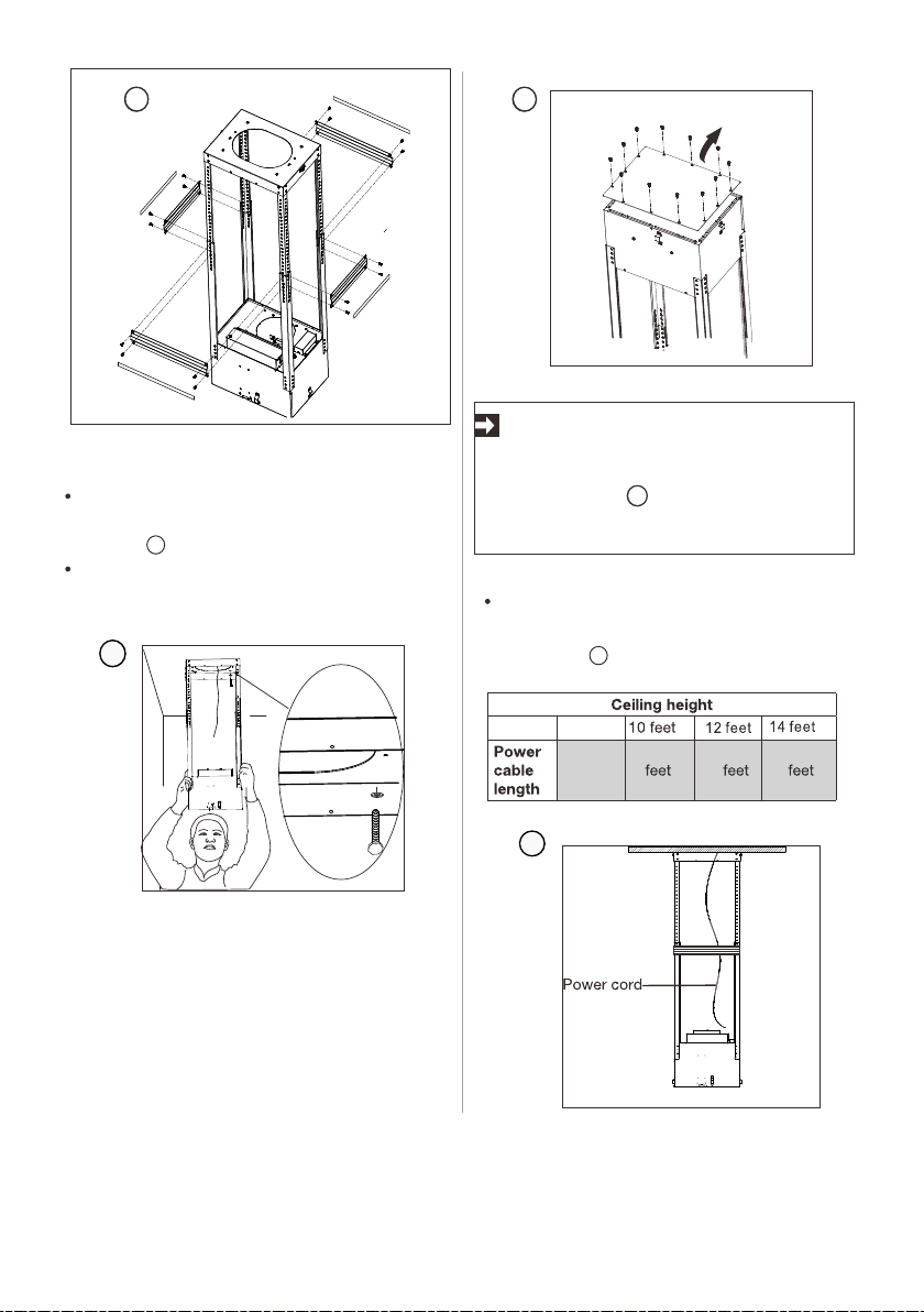
Step 4
Mount the truss part (2) onto the ceiling
with 4 sets of long screws (6) and washers
(8) (fig. ).
Make sure the power cable for the range
hood is routed inside the bracket.
8
Step 5
Depending on the ceiling height ensure
required power cable length. See the
table (fig. ) below for reference.
Fig.
10
IMPORTANT
Before mounting the truss part onto the
ceiling, please remove the supporting
plate firstly (fig. ). Remember to keep
these screws which will be reused in
step 8
Fig. Fig.
5 7 9
8 feet
3 feet
Fig.
7
8
9
9
10
10 ENGLISH
11 ENGLISH
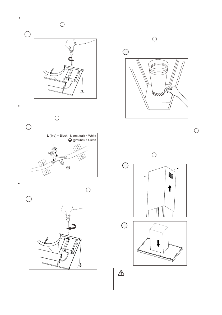
Loosen the 4 short screws from the
junction box (fig. )
Connect the incoming positive, neutral
and ground cables to the respective
terminals. (fig. ).
Mount the junction box onto the range
hood using 4 short screws (fig. ).
Step 6
Place the exhaust duct onto the outlet
and secure it with duct tape (not
provided) (fig. )
Fig.
Fig.
Fig.
Fig.
11
12
13
14
Step 7
Insert the top chimney into the truss (fig. ),
secure it with two screws(7).Insert the bottom
chimney in its seat so that it completely covers
the motor compartment and electrical
connection box(fig. ).
CAUTION
Danger of injury. The chimney skirts may
have some sharp edges.
Fig.
Fig.
15
16
11
12
13
14
15
16
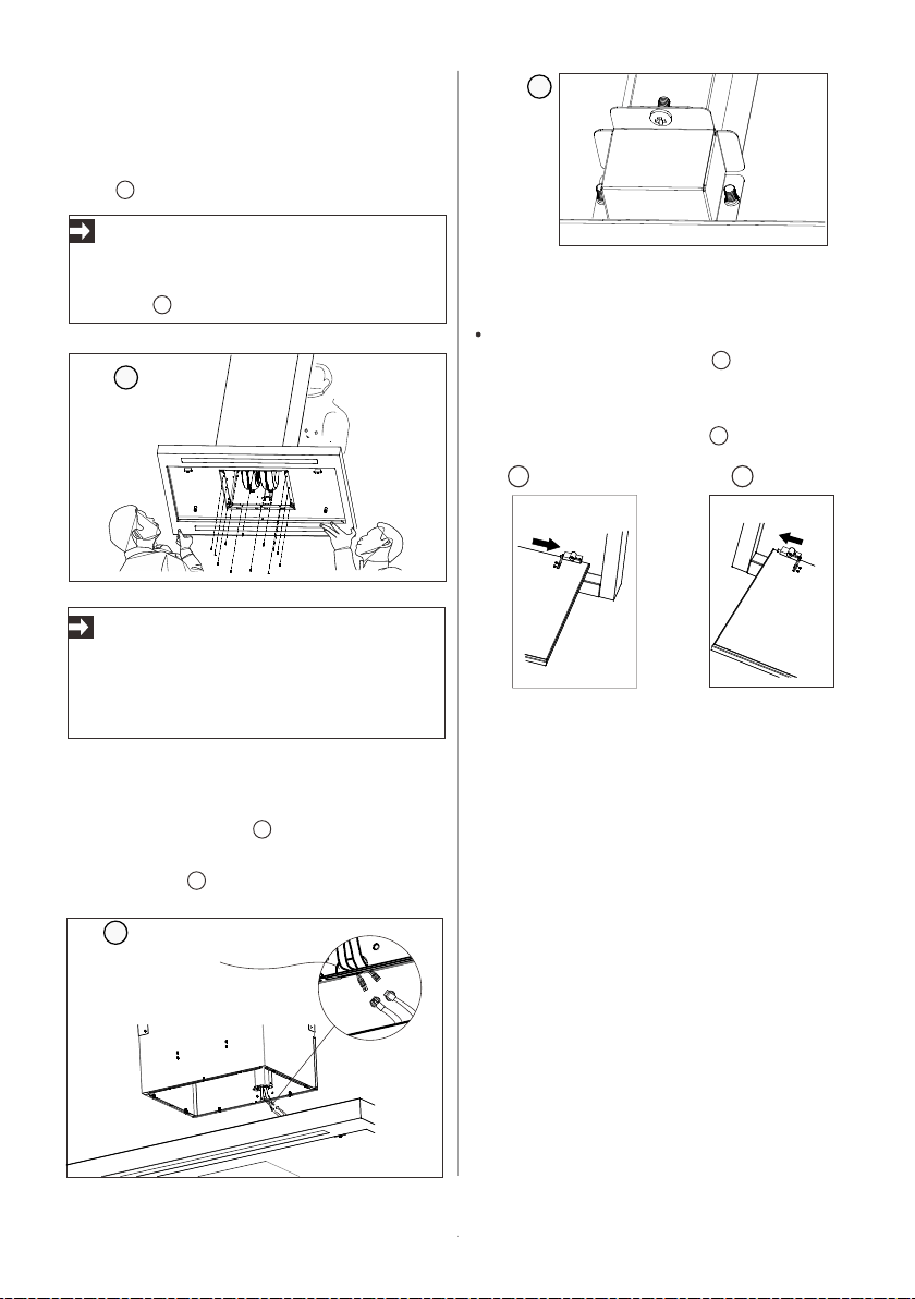
Step 8
Make sure the wire terminal passes
though the hole on the air house
(fig. )
Step 9
Connect as shown the wire terminal and the
controller terminal(fig. ). Ensure the wire
supplied cover secure firmly with three
screws (7)(fig. ).
Step 10
Install the aspiration plate to the hood body.
Fit the right bracket on the aspiration plate
to the right fixed hinge(fig. ),then push
the left hinge to the end to match the hole
of the left bracket on the plate and release
the hinge to lock them(fig. ).
12 ENGLISH
Fig.
Fig.
Fig. Fig.
IMPORTANT
Before hooking the hood onto the truss,
please make sure the aspiration plate
and filter have been removed from the
body to avoid it fall and injury to installer.
Fig.
18
19
20
21
Hook the hood body onto the truss,
ensuring it fits properly, secure the body to
the truss with 12 screws (7) then tighten
it(fig. ).
17
IMPORTANT
16
The hole on the air house
17
18
19
20 21
Recirculated air: Kitchen fumes are
removed and after purification are fed back
into the room through the upper ventilation
openings. The purification takes place via
metallic anti-grease filter. No wall
breakthrough is required for recirculated
air operation.
For operation of the range hood with
recirculation, recirculation kit #EHRKT62AS
is needed and can be purchased by calling
1-800-944-9044 (USA) or 1-800-265-8352
(Canada) Follow steps 1 to 4 from Installing
range hood to the wall(Exhaust operation)
chapter.
13 ENGLISH
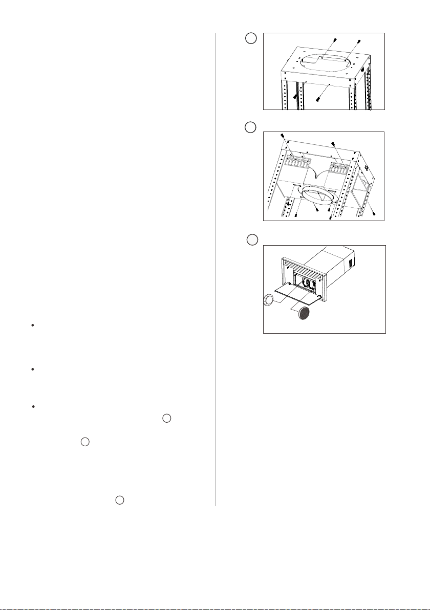
Fix the recirculation plate to mounting plate
with 4 supplied short screws(fig. ).Fix
the recirculation box with 8 supplied short
screws(fig. ).
Install charcoal filter to each side of the
blower motor by inserting the filters onto the
“T” shaped stud and twisting to lock them
into place.Reinstall the grease filter close
aspiration plate.(fig. )
Fig.
Fig.
Exhaust operation
Air recirculation operation
Installing range hood to the wall in
recirculation mode
22
23
24
Local building codes may require the use
of makeup air systems
when using ventilation systems greater
than specified CFM of air
movement. The specified CFM varies
from locale to locale.
Consult your HVAC professional for
specific requirements in your
area.
Makeup Air
22
23
Fig.
24

Press one of the speed button to
turn the appliance on.
Button Function
Press button to switch the
appliance off.
Press button for low speed.
Press button for medium speed.
Press button for high speed.
Press button to set the light to a low
intensity. Press the second time to set
the light to a medium intensity. Press
the third time to set the light to a high
intensity. Press the fourth time to turn
the light off.
Heat sensor
This product is equipped with a heat
sensor that will automatically turn the
vent fan ON at medium speed when
high temperatures are detected (over
158°F or 70°C).
If the vent fan is already running at low
speed and high temperatures are
detected, the vent fan will automatically
change to medium speed
14 ENGLISH
Turn on the range hood before starting to
cook.
Clean the filters frequently (refer to
Cleaning and maintenance below).
Use low speed for normal use and higher
speed for strong odors or fumes.
For best performance
SPECIAL FUNCTION
During this event, the vent fan speed
can be changed manually to high speed,
but not low speed or off.
When the heat sensor detects a
significant drop in temperature, then the
appliance will operate normally
OPERATION
It is recommended to use the range hood
while cooking and for several minutes
after cooking to reduce humidity and
odors inside your kitchen space.

CLEANING AND MAINTENANCE
DANGER
Always switch off the electricity supply at the
breaker box during installation, cleaning, or
maintenance.
NOTE
The efficiency of the range hood depends on
the cleanliness of the intake and filters.
Grease should not be allowed to accumulate
on hood or filter.
Use a soft cloth moistened with hand-warm mildly
soapy water or household cleaning detergent.
Never use metal pads, chemical, abrasive
material or stiff brush to clean the appliance.
15 ENGLISH
User service-Do not repair or replace any
part of the appliance unless specifically
recommended in the manual. All other
servicing should be referred to a qualified
technician.
IMPORTANT
Clean the appliance in the following intervals:
Charcoal filters:
Aluminum filter: The filter collects grease,
smoke and dust so the filter is directly affecting the
efficiency of the range hood. If not cleaned, the
grease residue(potential flammable) will saturate
on the filter. Clean it with household cleaning
detergent. The filter is dishwasher safe.
Recirculation box: clean the ventilation openings
on the top sides.
If the model is not vented to the outside, the air
will be recirculated through disposable
charcoal filters that help remove smoke and
odors.
The charcoal filters cannot be cleaned, they
must be replaced regularly (depending on
range hood usage).
Note: Do not rinse or put charcoal filters in a
dishwasher.
Note: Charcoal filters are not included with the
range hood.
Cleaning
E
Maintenance
Clean the filter every month to prevent risk
of fire.
IMPORTANT
Parts and accessories not provided
with your hood, or for replacement,
can be purchased at
or by calling 1-800-944-9044 (USA) or
1-800-265-8352 (Canada).
www.electrolux.com
16 ENGLISH
Power supply: 120V-60HZ
Motor Power: 330W
Lamp power: 24W for ECVI4262AS
TECHNICAL DATA
TROUBLESHOOTING
Problem Cause Solution
Excessive vibration
The appliance in not fixed properly
on the brackets.
Take down the appliance and check it is
properly fixed.
The fan blade is damaged.
The fan motor is not fixed tightly.
Switch off the appliance. Repair to be
carried out by qualified service
personnel only.
Light on, but fan does not
work.
The fan blade is jammed.
The motor is damaged.
Both light and fan do not work
Light bulb broken.
Problem with electrical connection.
Replace with a bulb with correct rating.
Check the electrical connection with
an electrician.
Suction performance is not
good.
Distance between the appliance
and the cooking place too large.
Metallic anti-grease filter is
dirty.
Readjust the distance(Page 7,
fig. 5 and table below)
Clean filters(see Cleaning and
maintenance).
Waste electrical products should
not be disposed of with household
waste. Please recycle where
Environmental protection
Charcoal filter is dirty
Charcoal filter(see Cleaning and
maintenance)
facilities exist. Check with your local
Authority or retailer for recycling advice.

WARRANTY INFORMATION
17 ENGLISH
Your appliance is covered by a one year
limited warranty. For one year from your
original date of purchase, Electrolux will pay
all costs for repairing or replacing any parts of
this appliance that prove to be defective in
materials or workmanship when such
appliance is installed, used and maintained in
accordance with the provided instructions.
Exclusions
This warranty does not cover the following:
1. Products with original serial numbers that
have been removed, altered or cannot be
readily determined.
2. Product that has been transferred from its
original owner to another party or removed
outside the USA or Canada.
3. Rust on the interior or exterior of the unit.
4. Products purchased “as-is” are not
covered by this warranty.
5. Products used in a commercial setting.
6. Service calls which do not involve
malfunction or defects in materials or
workmanship, or for appliances not in
ordinary household use or used other than
in accordance with the provided
instructions.
7. Service calls to correct the installation of
your appliance or to instruct you how to use
your appliance.
8. Expenses for making the appliance
accessible for servicing, such as removal of
trim,cupboards, shelves, etc., which are not
a part of the appliance when it is shipped
from the factory.
9. Service calls to repair or replace
consumable parts like grease or charcoal
filters.
10.Surcharges including, but not limited to,
any after hour, weekend, or holiday service
calls, tolls, ferry trip charges, or mileage
expense for service calls to remote areas,
including the state of Alaska.
11.Damages to the finish of appliance or
home incurred during installation, including
but not limited to floors, cabinets, walls, etc.
12.Damages caused by: services performed
by unauthorized service companies; use of
parts other than genuine Electrolux parts
or parts obtained from persons other than
authorized service companies; or external
causes such as abuse, misuse, inadequate
power supply, accidents, fires, or acts of
God.
DISCLAIMER OF IMPLIED WARRANTIES;
LIMITATION OF REMEDIES
CUSTOMER'S SOLE AND EXCLUSIVE
REMEDY UNDER THIS LIMITED WARRANTY
SHALL BE PRODUCT REPAIR OR
REPLACEMENT AS PROVIDED HEREIN.
CLAIMS BASED ON IMPLIED WARRANTIES,
INCLUDING WARRANTIES OF
MERCHANTABILITY OR FITNESS FOR A
PARTICULAR PURPOSE, ARE LIMITED TO
ONE YEAR OR THE SHORTEST PERIOD
ALLOWED BY LAW, BUT NOT LESS THAN
ONE YEAR. ELECTROLUX SHALL NOT BE
LIABLE FOR CONSEQUENTIAL OR
INCIDENTAL DAMAGES SUCH AS PROPERTY
DAMAGE AND INCIDENTAL EXPENSES
RESULTING FROM ANY BREACH OF THIS
WRITTEN LIMITED WARRANTY OR ANY
IMPLIED WARRANTY. SOME STATES AND
PROVINCES DO NOT ALLOW THE
EXCLUSION OR LIMITATION OF INCIDENTAL
OR CONSEQUENTIAL
DAMAGES, OR LIMITATIONS ON THE
DURATION OF IMPLIED WARRANTIES, SO
THESE LIMITATIONS OR EXCLUSIONS MAY
NOT APPLY TO YOU.
THIS WRITTEN WARRANTY GIVES YOU
SPECIFIC LEGAL RIGHTS. YOU MAY ALSO
HAVE OTHER RIGHTS THAT VARY FROM
STATE TO STATE.

If You Need Service
Keep your receipt, delivery slip, or some other
appropriate payment record to establish the
warranty period should service be required. If
service is performed, it is in your best interest to
obtain and keep all receipts. Service under this
warranty must be obtained by contacting
Electrolux at the addresses or phone numbers
below.
This warranty only applies in the USA and
Canada. In the USA, your appliance is
warranted by Electrolux Major Appliances
North America, a division of Electrolux Home
Products, Inc. In Canada, your appliance is
warranted by Electrolux Canada Corp.
Electrolux authorizes no person to change or
add to any obligations under this warranty.
Obligations for service and parts under this
warranty must be performed by Electrolux or an
authorized service company. Product features
or specifications as described or illustrated are
subject to change without notice.
18 ENGLISH
USA
1-877-435-3287
Electrolux Major Appliances
North America
10200 David Taylor Drive
Charlotte, NC 28262
Canada
1-800-265-8352
Electrolux Canada Corp.
5855 Terry Fox Way
Mississauga, Ontario, Canada
L5V 3E4

09050102432 A (EN) September 2020