O W N E R S G U I D E
M A R V E L O U T D O O R U N D E R C O U N T E R R E F R I G E R A T I O N
T H E O R I G I N A L R E F R I G E R A T I O N E X P E R T S S I N C E 1 8 9 2
F O R MO D E L # MO K R 1 2 4

NOTE
!
CAUTION
Important Safety Instructions
Warnings and safety instructions appearing in this guide
are not meant to cover all possible conditions and situa-
tions that may occur. Common sense, caution, and care
must be exercised when installing, maintaining, or operat-
ing this appliance.
Recognize Safety Symbols,
Words, and Labels.
CAUTION-Hazards or unsafe practices which could re-
sult in personal injury or property / product damage.
NOTE-Important information to help assure a problem
free installation and operation.
!
WARNING
WARNING - You can be killed or seriously injured
if you do not follow these instructions.
!
WARNING
State of California Proposition 65 Warning:
This product contains one or more chemicals known
to the State of California to cause cancer.
!
WARNING
State of California Proposition 65 Warning:
This product contains one or more chemicals known
to the State of California to cause birth defects or
other reproductive harm.
!
WARNING
WARNING - This unit contains R600a (Isobutane)
which is a ammable hydrocarbon. It is safe for regular
use. Do not use sharp objects to expedite defrosting.
Do not damage refrigerant circuit.
IMPORTANT SAFETY INSTRUCTIONS

TABLE OF CONTENTS
Tip: Click on any section below to jum
p directly there
Safety
Important Safety Instructions
Installation
Unpacking Your Appliance
Electrical
Operating Instructions
Using Your Beverage Dispenser
Energy Savng Tips
Service
Obtaining Service
Product Liability
Ordering Replacement Parts
R600a Specifications
System Diagnosis Guide
Warranty
3

NOTE
!
CAUTION
!
WARNING
WARNING - Dispose of the plastic bags which can
be a suocation hazard.
!
WARNING
WARNING - Help Prevent Tragedies
Child entrapment and suocation are not problems of
the past. Junked or abandoned refrigerators are still
dangerous - even if they sit out for "just a few hours".
If you are getting rid of your old refrigerator, please fol-
low the instructions below to help prevent accidents.
Before you throw away your old refrigerator or freezer:
• Take o the doors or remove the drawers.
• Leave the shelves in place so children may not
easily climb inside.
!
WARNING
EXCESSIVE WEIGHT HAZARD
Use two or more people to move product.
Failure to do so can result in personal injury.
Remove Interior Packaging
Your appliance has been packed for shipment with all parts
that could be damaged by movement securely fastened.
Remove internal packing materials and any tape holding in-
ternal components in place. The owners manual is shipped
inside the product in a plastic bag along with the warranty
registration card, and other accessory items.
Important
Keep your carton and packaging until your appliance has
been thoroughly inspected and found to be in good condi-
tion. If there is damage, the packaging will be needed as
proof of damage in transit. Afterwards please dispose of all
items responsibly.
Note to Customer
This merchandise was carefully packed and thoroughly
inspected before leaving our plant. Responsibility for its
safe delivery was assumed by the retailer upon acceptance
of the shipment. Claims for loss or damage sustained in
transit must be made to the retailer.
DO NOT RETURN DAMAGED MERCHANDISE TO THE
MANUFACTURER - FILE THE CLAIM WITH THE
RETAILER.
If the appliance was shipped, handled, or stored in other
than an upright position for any period of time, allow the ap-
pliance to sit upright for a period of at least 24 hours before
plugging in. This will assure oil returns to the compressor.
Plugging the appliance in immediately may cause damage
to internal parts.
UNPACKING YOUR APPLIANCE
4

Electrical Connection
A grounded 115 volt, 15 amp dedicated circuit is required.
This product is factory equipped with a power supply
cord that has a three-pronged, grounded plug. It must be
plugged into a mating grounding type receptacle in accor-
dance with the National Electrical Code and applicable lo-
cal codes and ordinances (see Figure 4). If the circuit does
not have a grounding type receptacle, it is the responsibility
and obligation of the customer to provide the proper power
supply. The third ground prong should not, under any cir-
cumstances, be cut or removed.
Figure 4
NOTE
Ground Fault Circuit Interrupters (GFCI) are prone to nui-
sance tripping which will cause the appliance to shut down.
GFCI’s are generally not used on circuits with power equip-
ment that must run unattended for long periods of time, un-
less required to meet local building codes and ordinances.
ELECTRICAL
Figure 2
Do not remove
ground prong
Figure 3
Electrical Shock Hazard
• Do not use an extension cord with this appliance.
They can be hazardous and can degrade product
performance.
• This appliance should not, under any circumstanc-
es, be installed to an un-grounded electrical supply.
• Do not remove the grounding prong from the power
cord. (See Figure 2).
• Do not use an adapter. (See Figure 3).
• Do not splash or spray water from a hose on the
appliance. Doing so may cause an electrical shock,
which may result in severe injury or death.
!
WARNING
5

Shelving
7KHXQLWLVVKLSSHGZLWKWKHVKHOYHVWDSHGLQSODFHLQ
the upper and the lower shelf positions. Remove them from
the refrigerator and arrange them as follows when setting
up your unit.
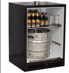
If you are not serving beer on tap, your keg dispenser can
be used as a refrigerator by placing both shelves on the
mounting brackets as shown in Figure 25. The shelves are
marked upper and lower, The upper shelf should be placed
in the top shelf position and the shelf marked lower should
be placed in the bottom shelf position.
Stored upper and
lower shelves
on side
Two shelves
installed
Figure 24
If you are using a quarter barrel of beer, you can add shelf
space for keeping your mugs chilled. The quarter barrel
PXVWVHWRQWKHÀRRULWFDQQRW¿WRQWKHVKHOIVHH
)LJXUH%HVXUHWKHZKLWHÀRRUSODWHLVLQWKHERWWRPRI
the interior compartment before positioning the barrel.
Figure 26
+DOIEDUUHONHJ
Installed upper
shelf above
barrel
Figure 25
Quarter barrel
Figure 27
,I\RXDUHXVLQJDKDOIEDUUHONHJRUEDUUHOVSODFH
the two shelves on the right side of the keg dispenser on
WKHWZRPRXQWLQJKRRNVIRUVWRUDJH6HH)LJXUH%H
VXUHWKHZKLWHÀRRUSODWHLVLQWKHERWWRPRIWKHLQWHULRU
FRPSDUWPHQWEHIRUHSRVLWLRQLQJWKHEDUUHOV
Two shelves
:KLWHÀRRUSODWH
:KLWHÀRRUSODWH
USING YOUR BEER DISPENSER
Stored lower shelf
If you are using the appliance as a refrigerator for per-
ishable foods, the set-point temperature should be set
EHWZHHQ)DQG)&DQG&
!
CAUTION
6

USING YOUR BEER DISPENSER
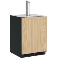
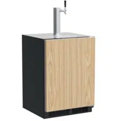
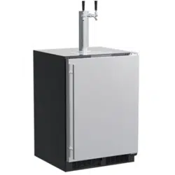
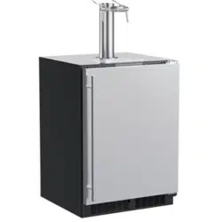
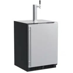
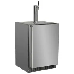
Polished stainless steel tower with clear beer line (single
RUGRXEOHGLVSHQVH
Tower Gasket
Phillips oval head screws
.QREIRU7RZHU)DXFHW+DQGOH
.HJFRXSOHUV
CO
2UHJXODWRUZLWKUHGJDVOLQHVDWWDFKHG
Empty 5 pound CO
2 tank
3ODVWLFFODPSVODUJHDQGVPDOO
Faucet wrench
Tools required for installation:
Flat bladed screwdriver
Phillips screwdriver
Pliers
Adjustable wrench or a 1
1
»8" open end wrench
1
»2" open end wrench
Barrel Sizes
1/6 barrel 1/4 Barrel 1/2 Barrel
Height
23
5
»16"
FP
14
13
»16"
FP
23
5
»16"
FP
Diameter
9
1
»4"
FP
17"
FP
17" to 17
1
»4"
WRFP
Gallons 5.23 7.75 15.5
#12 ounce
Glasses
53 82 163
This beer dispensing unit will support one half (
1
»2EDUUHO
or one quarter (
1
»4EDUUHO7KHGRXEOHGUDIWWRZHUXQLWVFDQ
support two sixth (
1
»6EDUUHOVRIEHHU6HHFKDUWEHORZIRU
quantity of beer in each barrel size.
Keg Size
#of kegs per
5 pound CO2 Tank
5 gallon Corny 15 to 22
1/6 barrel 14 to 21
1/4 Barrel 10 to 14
1/2 Barrel 5 to 7
CO
2FDQEHGDQJHURXV,ILWEHFRPHVGLI¿FXOWWR
breathe and/or your head starts to ache, a high
concentration of carbon dioxide may be present.
Leave the area immediately.
• The CO
2 tank must always be connected to the
regulator. Never connect the tank to the keg.
• The CO2 tank must be securely mounted in the
upright position. Secure it with the chain pro-
vided.
• Never drop or throw the CO
2 tank.
• Keep the CO2 tank away from heat.
• Ventilate the area after a CO2 leak.
!
WARNING
1. Remove shelving and packaged components from
the interior of the refrigerator before beginning the
assembly process.
2. Take your empty 5 pound CO2 tank to your local gas
VXSSO\GHDOHUWREH¿OOHG<RXFDQXVXDOO\¿QGWKHPLQ
your "yellow pages" under "Welding Supply" or "Fire
Protection". One 5 pound tank can process many kegs
VHHWDEOH'
3. Tower Mounting: DO NOT REMOVE INSULATION
INSIDE OF STAINLESS STEEL TOWER. INSULATION
KEEPS BEER IN CLEAR LINE COLD AND FRESH.
Mounting Tower to Refrigerator Top: Remove the
foam plug from the porthole and DO NOT reseal.
&OHDUDQFHLQSRUWKROHLVQHFHVVDU\IRUFROGDLUWRÀRZ
into the tower and keep the beer line cold.
Mounting Tower to Counter Top: Remove the foam
plug from the porthole and use to "bridge" the gap
between the top of the cabinet and the underside of the
FRXQWHU/HDYHDGHTXDWHFOHDUDQFHIRUFROGDLUWRÀRZ
into the tower and keep the beer line cold.
!
CAUTION
Tap Equipment and Assembly
Your dispensing kit includes the following parts:
7

B
B
B
B
5 Pound
CO2 Tank
5 Pound
CO
2 Tank
A
A
A
A
A
A
C
C
C
C
C
C
Regulator
with red
airline
Regulator
with red
airline
Keg
Coupler
Keg
Coupler
Keg
Coupler
Single
Dispense
Tower
Double
Dispense
Tower
A
C
Hose clamps
use for connections
and
A
C
Hose clamps
use for connections
and
A A
Single Dispense Tower Kit
Connect to ,etc........
A A
Double Dispense Tower Kit
Connect to ,etc........
USING YOUR BEER DISPENSER
8

4.
5.
6.
If you are installing your keg refrigerator under a coun-
ter you will need to drill 5 holes in the counter top to
PRXQWWKHWRZHU7KH¿UVWKROHLVD
1
»2" diameter hole
located at the center of the tower for the beer line, lo-
cate approximately 13
1
»2FPIURPWKHIURQWHGJH
of the counter top (based on a counter top depth of
25
5
»161H[WGULOOWKHWRZHUPRXQWLQJKROHVSHUWKHGL-
mensions. The hole diameter is dependent on the
counter top material and if screw anchors are required.
The screws supplied are in the literature pack and are a
#10 x 1" type AB stainless steel screw. Mark and cut
the rectangular cutout for the drain sump. After the
holes are drilled and the keg refrigerator is in place
under the counter top feed the beer line through the
tower gasket, the 1
1
»2" hole in the counter top and the
hole in the top of the keg refrigerator. Mount the tower
to the counter top with the 4 screws provided. Place
the counter top drain sump, from the literature pack, in
the rectangular hole with the radius cutout to the rear
around the tower and place the grate in the sump.
Mount the regulator to the CO
2WDQNFRQQHFWLRQ
B
Note that the regulator has left hand threads and has to
be turned counterclockwise to tighten. Tighten with the
adjustable wrench or the 1
1
»8" open end wrench.
&RQQHFWWKHUHGDLUOLQHVIURPWKHUHJXODWRUWRWKH
largeDLUOLQH¿WWLQJRQWKHNHJFRXSOHUZLWKDlarge
KRVHFODPSFRQQHFWLRQ
C
7. Connect the clear beer line from the tower to the small
DLUOLQHILWWLQJRQWKHNHJFRXSOHUZLWKDsmall hose
FODPSFRQQHFWLRQ
A
8. Locate the CO2 tank in the corner of the refrigerator
and secure with the chain. Close the faucet handle on
the tower.
Diameter
to suit
Rear of counter top
6
1
»8"
FP
12
1
»4"
FP
2
7
»8"
FP
4
1
»4"
FP
6
3
»8"
FP
1
3
»8"
FP
typical
1
1
»2PP
Diameter
counter
top depth
25
5
»16"
FP
1
»4PP
radii,
typical
Grate from top of
beer dispenser
Counter top
sump from
literature pack
Tower
!
CAUTION
The cutout dimensions shown above are based on a
25
5
»16FPGHHSFRXQWHUWRS<RXUFRXQWHUWRSPD\
be different than this and require other front to back
dimen-sioning. Refer to the product dimensions when
determining the required dimensions.
USING YOUR BEER DISPENSER
9

Dog ears on keg
Coupler
extended
9. Hooking up the keg coupler to the keg: Verify the cou-
SOHULVLQWKH2))SRVLWLRQ$OLJQWKH lugs on the keg
with the corresponding openings on the keg coupler
and turn clockwise until the coupler stops DERXW
3XVKGRZQDQGWZLVWWKHWRSRIWKHFRXSOHU clockwise to
allow gas to enter the keg.
Chain-The chain is fastened and taped
to the top of the interior liner. Remove
the tape and secure the CO
2 tank in
place in the back right corner. Loop
chain around top of tank and connect
with "S" hook.
Push faucet handle back toward
tower to close the faucet
Rotate the top of the coupler coun-
ter clockwise to extend the coupler
to the to the "OFF"position.
Connect
with "S"
hook
USING YOUR BEER DISPENSER
10

USING YOUR BEER DISPENSER
Mounting
bracket
6FUHZV
Remove foam plug
from hole port
!
CAUTION
If the CO2 WDQNLVSODFHGRQWKHÀRRULWPXVWEHVHFXUHGLQ
the upright position with a chain or other means to prevent
it from being tipped over.
Reseal hole
around tubing with
the foam plug
CO2 tank
placed in the
bracket
The foam insulation plugs provided in the portholes are
CRITICAL to proper functioning of the unit and preventing
frost build up that can cause damage to the unit and/or
refrigerator contents. ALWAYS reseal the CO2 line porthole
ZLWKWKHSURYLGHGLQVXODWLRQSOXJVRQFHDOOOLQHVhave been
properly installed.
NOTE
Optional CO2
tank external mounting bracket:
The optional mounting bracket is designed to hold the 5#
CO
2 cylinder that comes with the beer dispenser. Larger
cylinders may be purchased from a third party and mounted
externally. Use the hole port on the rear of the cabinet to
run the CO2 line to the keg.
Many options are available for mounting the CO
2 tank
outside of the beer dispenser to gain additional cold
storage space inside.
Secure the optional external mounting bracket on the
back of the beer dispenser (this is ideal for mobile
units) or mount within adjacent cabinetry (ideal for
undercounter built-in units:
0RXQWWKHVFUHZV[
3
»4ÀDWKHDGPDFKLQH
VFUHZVSURYLGHGZLWKWKHEUDFNHWLQWKHUHDURIWKH
appliance. Do not completely tighten. Place WKHNH\KROH
VORWVLQWKHIODQJHVRIWKHEUDFNHWRYHUWKHfour screws and
tighten them to secure the bracket to the back of the
cabinet. The bracket can also be fastened
to adjacent cabinetry using the provided #10 x
3
»4" wood
screws.
Mark the hole locations where required using a pencil and
the slots in the mounting bracket. Drill appropriate pilot
KROHVGHSHQGLQJRQWKHPDWHULDO\RXDUHPRXQWLQJWRDQG
secure the bracket per the above instructions.
NOTE
Consider the length of the red air line when choosing a
place for the CO
2 tank. The red air line supplied is 4 feet
PHWHUVORQJ
With the gauges mounted to the CO
2 tank place the tank in
the mounting bracket.
Remove the foam plug from the hole port, and feed the
red CO2 line through the rear wall and out the coil cover on
the inside of the cabinet. Connect the red CO
2 line to the
keg coupler.
Reseal the hole in the back of the cabinet with the foam
plug.
11

CO2 Regulator (Double Dispense Tower)
Your beer dispenser comes equipped with a 5 pound CO2
tank and a dual gauge regulator. The lower gauge should
EHUHDGLQJDSSUR[LPDWHO\SVLEDUZKHQWKHWDQNLV
SURSHUO\¿OOHGDQGWKHWDQNLVQRWLQWKHUHIULJHUDWRUDWURRP
WHPSHUDWXUH7KHWDQNZLOOUHDGOHVVZKHQFKLOOHG8VHWKLV
lower gauge as an indicator of how much CO
2 you have left
in the tank.
The upper gauge reads the pressure being supplied to the
beer keg. Follow the procedure below to adjust the pres-
VXUHWRSVLWREDUIRUODJHUEHHURUSVL
WREDUIRUDOHV
To adjust the pressure (Upper Gauge):
1. Close the shutoff valves at the bottom of the regulator.
2. Be sure the faucet handle is closed on the tower.
3. Loosen the lock nut by turning ඞ counterclockwise us-
ing the
1
»2" open end wrench until loose, this will allow
adjustment of the pressure adjustment screw.
4. :LWKWKHIODWEODGHGVFUHZGULYHUWXUQWKHDGMXVWPHQW
screw ඟclockwise to increase the pressure or ඞcoun-
terclockwise to decrease the pressure.
5. Open the shutoff valve on the bottom of the regula-tor.
The gauge reading may drop but will return very
quickly.
6. 3XOOWKHULQJRQWKHNHJFRXSOHUWRDOORZWKHJDVWRIORZ
momentarily.
7. 0DNHDQ\ILQHDGMXVWPHQWVLIQHFHVVDU\ZLWKWKH
DGMXVW-ment screw.
8. Tighten the locknut with the
1
»2" open end wrench by
turning clockwise ඟ
CO2 Regulator (Single Dispense Tower)
Your beer dispenser comes equipped with a 5 pound CO2
tank and a single gauge regulator. The gauge reads the
pressure being supplied to the beer keg. Follow the proce-
dure below to adjust the pressure to 12 - 14 psi (0.8 to 1
EDUIRUODJHUEHHURUSVLWREDUIRUDOHV
To adjust the pressure (Single Gauge):
1. Close the shutoff valve at the bottom of the regulator.
2. Be sure the faucet handle is closed on the tower.
3. Loosen the lock nut by turning ඞ counterclockwise us-
ing the
1
»2" open end wrench until loose, this will allow
adjustment of the pressure adjustment screw.
4. :LWKWKHIODWEODGHGVFUHZGULYHUWXUQWKHDGMXVWPHQW
screw ඟclockwise to increase the pressure or ඞcoun-
terclockwise to decrease the pressure.
5. Open the shutoff valve on the bottom of the regula-tor.
The gauge reading may drop but will return very
quickly.
6. 3XOOWKHULQJRQWKHNHJFRXSOHUWRDOORZWKHJDVWRIORZ
momentarily.
7. 0DNHDQ\ILQHDGMXVWPHQWVLIQHFHVVDU\ZLWKWKH
DGMXVW-ment screw.
8. Tighten the locknut with the
1
»2" open end wrench by
turning clockwise ඟ
Ring on keg
coupler
(Regulator for 6LQJOH
'LVSHQVH7RZHU
(Regulator for 'RXEOH
'LVSHQVH7RZHU
VKXWRII
valves (closed
SRVLWLRQVKRZQ
Upper Gauge
Pressure Gauge
Lower Gauge
Pressure
Adjustment
Screw
Lock Nut
USING YOUR BEER DISPENSER
Pressure
Adjustment
Screw
Lock Nut
shutoff valve
(closed posi-
WLRQVKRZQ
12

Drain kit (All Models):
The drain kit is shipped in
place and ready to use. To empty: Pull drain hose out of
bottle cap, remove bottle from unit, unscrew cap and dis-
card waste and rinse bottle. Reinstall bottle in unit.
Unscrew
cap
Removable
grate for clean-
ing sump area
Cleaning the drain sump:
On a free standing beer dispenser remove the Marvel
grate from in front of the tower, clean with soap and water
and dry before reinstalling. Clean the sump area with
soapy ZDWHUDQGGU\
On a built in beer dispenser remove the Marvel grate
and counter top sump, clean with soap and water and dry
before reinstalling. Clean the sump area with soapy water
DQGGU\
Marvel grate
Counter top
sump
Clean and dry
sump area
Push faucet handle back toward
tower to close the faucet
USING YOUR BEER DISPENSER
13

ENERGY SAVING TIPS
4. Plug your appliance into a dedicated power circuit. (Not
shared with other appliances).
5. When initially loading your new product, or whenever
large quantities of warm contents are placed within
refrigerated storage compartment, minimize door
openings for the next 12 hours to allow contents to pull
down to compartment set temperature.
6. Maintaining a relatively full storage compartment will
require less appliance run time than an empty compart-
ment.
7. Ensure door closing is not obstructed by contents
stored in your appliance.
8. Allow hot items to reach room temperature before plac-
ing in product.
9. Minimize door openings and duration of door openings.
10. Use the warmest temperature control set temperature
that meets your personal preference and provides the
proper storage for your stored contents.
11. When on vacation or away from home for extended pe-
riods, set the appliance to warmest acceptable tem-
perature for the stored contents.
12. Set the control to the “o” position if cleaning the
appliance requires the door to be open for an extended
period of time.
13. For wine storage products:
When serving temperatures are not required,
return the compartment(s) set temperature to the
ideal red and white wine long term storage tem-
perature of 13°C / 55°F.
The following suggestions will minimize the
cost of operating your refrigeration appliance.
1. Do not install your appliance next to a hot appliance
(cooker, dishwasher, etc.), heating air duct, or other
heat sources.
2. Install product out of direct sunlight.
3. Ensure the front grille vents at front of appliance be-
neath door are not obstructed and kept clean to allow
ventilation for the refrigeration system to expel heat.
14

If Service is Required:
• If the product is within the rst year warranty period
please contact your dealer or call Marvel Customer
Service at 616.754.5601 for directions on how to obtain
warranty coverage in your area.
• If the product is outside the rst year warranty period,
Marvel Customer Service can provide recommenda-
tions of service centers in your area. A listing of autho-
rized service centers is also available at www.marvelre-
frigeration.com under the service and support section.
• In all correspondence regarding service, be sure to
give the service number, serial number, and proof of
purchase.
• Try to have information or description of nature of the
problem, how long the appliance has been running, the
room temperature, and any additional information that
may be helpful in quickly solving the problem.
• Table "B" is provided for recording pertinent information
regarding your product for future reference.
For Your Records
Date of Purchase
Dealer’s name
Dealer’s Address
Dealer’s City
Dealer’s State
Dealer’s Zip Code
Appliance Serial Number
Appliance Service Number
Date Warranty Card Sent (Must
be within 10 days of purchase).
Table B
OBTAINING SERVICE
15

Ordering Replacement Parts
O
"
"
6
6
6
M
M
M
M
m.
Ordering Replacement Parts
16

Ordering Replacement Parts
O
"
"
6
6
6
M
M
M
M
m.
Ordering Replacement Parts
17

R-600A Specifications
&
H
an
dl
in
g
R-600A Specications
,
.
'
18

IA WARNING I
19

SYSTEM REPAIR
R-600A Specications
LEAK DETECTION
20

RECHARGING
SUMMARY
21

System Diagnosis Guide
System Diagnosis Guide
22

HOUSEHOLD PRODUCT WARRANTY
Marvel Refrigeration (Marvel) Limited Warranty
ONE YEAR LIMITED PARTS & LABOR WARRANTY
For one year from the date of original purchase, this warranty covers all parts and labor to repair or replace any part of the product that proves to
be defecve in materials or workmanship. For products installed and used for normal residenal use, material cosmec defects are included in this
warranty, with coverage limited to 60 days from the date of original purchase. All service provided by Marvel under the above warranty must be
performed by a Marvel factory authorized servicer, unless otherwise specied by Marvel. Service provided during normal business hours.
TWO YEAR LIMITED PARTS & LABOR WARRANTY (MARVEL PROFESSIONAL PRODUCTS)
For two years from the date of original purchase, this warranty covers all parts and labor to repair or replace any part of the product that proves to
be defecve in materials or workmanship. For products installed and used for normal residenal use, material cosmec defects are included in this
warranty, with coverage limited to 60 days from the date of original purchase. All service provided by Marvel under the above warranty must be
performed by a Marvel factory authorized servicer, unless otherwise specied by Marvel. Service provided during normal business hours.
AVAILABLE THIRD YEAR LIMITED WARRANTY (MARVEL PROFESSIONAL PRODUCTS)
For designated Marvel Professional product, Marvel oers a one year extension of the two year warranty coverage from the date of purchase, free
of charge. To take advantage of this third year warranty, you must register your product with Marvel within 60 days from the date of purchase at
marvelrefrigeraon.com and provide proof of purchase.
LIMITED FIVE YEAR SEALED SYSTEM WARRANTY
For ve years from the date of original purchase, Marvel will repair or replace the following parts, labor not included, that prove to be defecve in
materials or workmanship: compressor, condenser, evaporator, drier, and all connecng tubing. All service provided by Marvel under the above war-
ranty must be performed by a Marvel factory authorized servicer, unless otherwise specied by Marvel. Service provided during normal business
hours.
WARRANTY TERMS
These warranes apply only to products installed in any one of the y states of the United States, the District of Columbia, or the ten provinces of
Canada. The warranes do not cover any parts or labor to correct any defect caused by negligence, accident or improper use, maintenance, instal-
laon, service, repair, acts of God, re, ood or other natural disasters. The product must be installed, operated, and maintained in accordance with
the Marvel User Guide.
The remedies described above for each warranty are the only ones that Marvel will provide, either under these warranes or under any warranty
arising by operaon of law. Marvel will not be responsible for any consequenal or incidental damages arising from the breach of these warranes
or any other warranty, whether express, implied, or statutory. Some states do not allow the exclusion or limitaon of incidental or consequenal
damages, so the above limitaon or exclusion may not apply to you. These warranes give you specic legal rights, and you may also have other
rights which vary from state to state.
Any warranty that may be implied in connecon with your purchase or use of the product, including any warranty of merchantability or any war-
ranty t for a parcular purpose is limited to the duraon of these warranes, and only extends to ve years in duraon for the parts described
in the secon related to the ve year limited warranty above. Some states do not allow limitaons on how long an implied warranty lasts, so the
above limitaons may not apply to you.
• The warranes only apply to the original purchaser and are non-transferable.
• These warranes cover products installed and used for normal residenal use only.
• The warranes apply to units operated outside only if designed for outdoor use by model and serial number.
• Replacement water lters, light bulbs, and other consumable parts are not covered by these warranes.
• The start of Marvel’s obligaon is limited to four years aer the shipment date from Marvel.
• In-home instrucon on how to use your product is not covered by these warranes.
• Food, beverage, and medicine loss are not covered by these warranes.
• If the product is located in an area where Marvel factory authorized service is not available, you may be responsible for a trip charge or
you may be required to bring the product to a Marvel factory authorized service locaon at your own cost and expense.
• Units purchased aer use as oor displays, and/or cered recondioned units, are covered by the limited one year warranty only and no
coverage is provided for cosmec defects.
• Signal issues related to Wi-Fi connecvity are not covered by these warranes.
For parts and service assistance, or to nd Marvel factory authorized service near you, contact Marvel Refrigeraon:
MarvelRefrigeraon.com • techsupport@MarvelRefrigeraon.com • +616.754.5601
1260 E. Van Deinse St., Greenville, MI 48838
23