2005 Sony Corporation
Printed in Korea
POWER OUTPUT AND TOTAL HARMONIC DISTORTION
60 watts per channel minimum continuous average power into 4 ohms,
both channels driven from 20 Hz to 20 kHz with no more than 0.08 %
total harmonic distortion per Car Audio Ad Hoc Committee standards.
The model and serial numbers are located on the bottom of the unit.
Record the serial number in the space provided below.
Refer to these numbers whenever you call upon your Sony dealer regarding this product.
Model No. XM-SD46X Serial No.
2-514-766-11 (1)
Circuit system OTL (output transformerless)
circuit
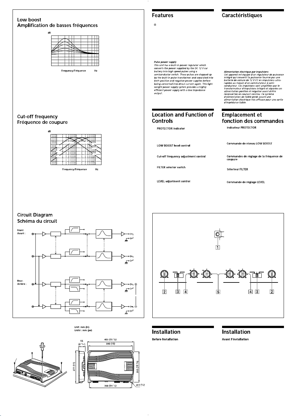
Pulse power supply
Inputs RCA pin jacks
High level input connector
Outputs Speaker terminals
Suitable speaker impedance
2 – 8 (stereo)
4 – 8 (when used as a bridging
amplifier)
Maximum outputs Four speakers:
120 W 4 (at 4 )
150 W 4 (at 2 )
Three speakers:
120 W 2 + 300 W 1 (at 4 )
Rated outputs (supply voltage at 14.4 V)
Four speakers:
60 W RMS 4 (20 Hz – 20 kHz,
0.08 % THD + N, at 4 )
75 W RMS 4 (20 Hz – 20 kHz,
0.1 % THD + N, at 2 )
Three speakers:
60 W RMS 2 + 150 W RMS 1 (20
Hz – 20 kHz, 0.1 % THD + N, at 4 )
SN Ratio 97 dBA (Reference 1W into 4 )
Frequency response 5 Hz – 50 kHz ( dB)
Harmonic distortion 0.005 % or less (at 1 kHz)
Input level adjustment range
0.3 – 6.0 V (RCA pin jacks)
1.2 – 12 V (High level input)
High-pass filter 50 – 300 Hz, –12 dB/oct
Low-pass filter 50 – 300 Hz, –12 dB/oct
Low boost 0 – 10 dB (40 Hz)
Power requirements 12 V DC car battery
(negative ground)
Power supply voltage
10.5 – 16 V
Current drain at rated output: 31 A (4 )
Remote input: 1 mA
Dimensions Approx. 403 55 277 mm
(w/h/d) (15
7
/
8
2
1
/
4
11 in) not
incl. projecting parts and controls
Mass Approx. 4.7 kg (10 lb 6 oz) not incl.
accessories
Supplied accessories Mounting screws (4)
High level input cord (1)
Protection cap (1)
Design and specifications are subject to change without
notice.
The following checklist will assist in the correction of most problems which you may encounter with your unit.
Before going through the checklist below, refer to the connection and operating procedures.
La liste suivante vous aidera à ré soudre la plupart des problèmes que vous pouvez rencontrer avec cet
appareil. Avant de passer la liste en revue, vé rifiez les procé dures de raccordement et d’utilisation.
Le fusible est grillé . t Remplacez les deux fusibles par des neufs.
Le fil de masse n’est pas connecté correctement.
t Fixez correctement le fil de masse à un point mé tallique de la voiture.
La tension entrant sur la borne e commande à distance est trop faible.
• L’autoradio raccordé n’est pas sous tension.
t Mettez l’autoradio sous tension.
• Le systè me utilise trop d’amplificateurs. t Utilisez un relais.
Vé rifiez la tension de la batterie (10,5 – 16 V).
Coupez l’interrupteur d’alimentation. Les sorties de haut-parleur sont court-
circuité es. t Remédiez à la cause du court-circuit.
Coupez l’interrupteur d’alimentation. Assurez-vous que le cordon de haut-
parleur et le câ ble de masse sont correctement branché s.
L’appareil chauffe anormalement.
• Utilisez des haut-parleurs d’une impé dance appropriée.
t 2 – 8 (sté ré o) , 4 – 8 (utilisé comme amplificateur à pont).
• Installez l’appareil dans un endroit bien aé ré.
Le protecteur thermique est activé . t Réduisez le volume.
Les câ bles d’alimentation sont installés trop prè s des câ bles à broches RCA.
t Eloignez les câ bles d’alimentation des câ bles à broches RCA.
Le fil de masse n’est pas connecté correctement.
t Fixez correctement le fil de masse à un point mé tallique de la voiture.
Les fils né gatifs des haut-parleurs touchent la carrosserie de la voiture.
t Eloignez les fils de la carrosserie de la voiture.
Sé lecteur FILTER est réglé sur la position « LPF ».
• Le ré glage par dé faut du sé lecteur FILTER est « OFF ».
t Lors du raccordement du haut-parleur à gamme étendue, ré glez ce
commutateur sur « OFF ».
La commande de ré glage de LEVEL est mal ré glé e. Tournez la commande de
ré glage LEVEL dans le sens des aiguilles d’une montre.
Circuiterie Circuit OTL (Sortie sans
transformateur)
Alimentation par impulsions
Entré es Prises à broche RCA
Connecteur d’entré e haut niveau
Sorties Bornes de haut-parleurs
Impédance approprié e pour les enceintes
2 – 8 (sté réo)
4 – 8 (utilisé comme
amplificateur à pont)
Sorties maximales Quatre haut-parleurs :
120 W 4 (à 4 )
150 W 4 (à 2 )
Trois haut-parleurs :
120 W 2 + 300 W 1 (à 4 )
Sorties nominales (tension d’alimentation de 14,4 V)
Quatre haut-parleurs :
60 W RMS 4 (20 Hz – 20 kHz,
0,08 % THD + N, à 4 )
75 W RMS 4 (20 Hz – 20 kHz,
0,1 % THD + N, à 2 )
Trois haut-parleurs :
60 W RMS 2 + 150 W RMS 1 (20
Hz – 20 kHz, 0,1 % THD + N, à 4 )
Rapport signal/bruit 97 dBA (Ré férence 1 W dans 4
Ré ponse en fréquence
5 Hz – 50 kHz ( dB)
Distorsion harmonique
0,005 % ou inférieure (à 1 kHz)
Plage de ré glage du niveau d’entré e
0,3 – 6,0 V (prises à broche RCA)
1,2 – 12 V (entré e haut niveau)
Filtre passe-haut 50 – 300 Hz, –12 dB/oct
Filtre passe-bas 50 – 300 Hz, –12 dB/oct
Amplification de basses fré quences
0 – 10 dB (40 Hz)
Alimentation Batterie de voiture, courant continu
12 V (masse né gative)
Tension d’alimentation
10,5 – 16 V
Courant à la sortie nominale : 31 A (4 )
Entré e de commande à distance :
1 mA
Dimensions Env. 403 55 277 mm
(l/h/p) (15
7
/
8
2
1
/
4
11 po)
parties saillantes et commandes
non comprises
Poids Env. 4,7 kg (10 liv 6 on) accessoires
non compris
Accessoires fournis Vis de montage (4)
Cordon d’entré e haut niveau (1)
Cache de protection (1)
La conception et les spé cifications peuvent ê tre modifié es
sans pré avis.
1 2
( 4)
3
The fuse is blown. t Replace both the fuses with a new one.
The ground wire is not securely connected.
t Fasten the ground wire securely to a metal point of the car.
The voltage going into the remote terminal is too low.
• The connected car audio unit is not turned on. t Turn on the car audio unit.
• The system employs too many amplifiers. t Use a relay.
Check the battery voltage (10.5 – 16 V).
Turn off the power switch. The speaker outputs are short-circuited.
t Rectify the cause of the short circuit.
Turn off the power switch. Make sure the speaker cord and ground wire are
securely connected.
The unit heats up abnormally.
• Use speakers with suitable impedance.
t 2 – 8 (stereo) , 4 – 8 (when used as a bridging amplifier).
• Make sure to place the unit in a well ventilated location.
The thermal protector is activated. t Reduce the volume.
The power connecting wires are installed too close to the RCA pin cords.
t Keep the power connecting wires away from the RCA pin cords.
The ground wire is not securely connected.
t Fasten the ground wire securely to a metal point of the car.
Negative speaker cords are touching the car chassis.
t Keep the cords away from the car chassis.
The FILTER selector switch is set to the “LPF” position.
• By default, the FILTER selector switch is in “OFF” position.
t When connecting the full range speaker, set to the “OFF” position.
The LEVEL adjustment control is not appropriate. Turn the LEVEL adjustment
control in the clockwise direction.
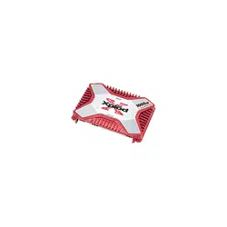
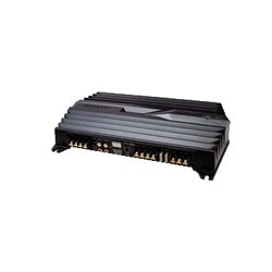
• Maximum power output of 120 W per channel (at 4
).
• This unit can be used as a bridging amplifier with a
maximum output of 300 W.
• Direct connection can be made with the speaker
output of your car audio unit if it is not equipped
with a line output (High level input connection).
• Built-in variable LPF (Low-pass filter), HPF (High-
pass filter) and low boost circuit.
• Protection circuit and indicator provided.
• Pulse power supply
*
for stable, regulated output
power.
*
•Puissance de sortie maximale de 120 W par
canal (à 4 W).
•Cet appareil peut ê tre utilisé comme
amplificateur en pont d’une sortie maximale de
300 W.
•Une connexion directe est possible avec la sortie
haut-parleur de votre autoradio si celle-ci n’est
pas é quipé e d’une sortie de ligne (connexion
d’entré e haut niveau).
•Filtre passe-bas (LPF), filtre passe-haut (HPF)
variables et circuit d’amplification des basses
fré quences.
•Avec circuit et indicateur de protection.
•Alimentation électrique par impulsions* pour
une puissance de sortie stable, ré gulée.
*
1
When the PROTECTOR is activated, the
indicator lighhts up in red.
When the PROTECTOR is activated refer to
the Troubleshooting Guide.
2
Turn this control to boost the frequencies
around 40 Hz to a maximum of 10 dB.
3
Sets the cut-off frequency (50 – 300 Hz) for the
low-pass or high-pass filters.
4
When the switch is in the LPF position, the
filter is set to low-pass. When in the HPF
position, the filter is set to high-pass.
5
The input level can be adjusted with this
control. Turn it in the clockwise direction
when the output level of the car audio
unit
seems low.
1
Lorsque PROTECTOR est activé , l’indicateur
s’allume en rouge.
Lorsque PROTECTOR est activé , reportez-
vous au guide de dé pannage.
2
Tournez cette commande pour amplifier les
fré quences autour de 40 Hz jusqu’à un
maximum de 10 dB.
3
Rè gle la fré quence de coupure (50 – 300 Hz)
des filtres passe-bas ou passe-haut.
4
Lorsque le sé lecteur est en position LPF, le
filtre est ré glé sur passe-bas. Lorsqu’il est en
position HPF, le filtre est ré glé sur passe-haut.
5
Le niveau d’entré e peut se ré gler avec cette
commande. Tournez cette commande dans le
sens des aiguilles d’une montre lorsque le
niveau de sortie de l’autoradio semble faible.
• Mount the unit either inside the trunk or under a
seat.
• Choose the mounting location carefully so the unit
will not interfere with the normal movements of the
driver and it will not be exposed to direct sunlight
or hot air from the heater.
• Do not install the unit under the floor carpet, where
the heat dissipation from the unit will be
considerably impaired.
First, place the unit where you plan to install it, and
mark the positions of the four screw holes on the
surface of the mounting board (not supplied). Then
drill the holes approximately 3 mm (
1
/
8
in) in
diameter and mount the unit onto the board with the
supplied mounting screws. The supplied mounting
screws are 15 mm (
19
/
32
in) long. Therefore, make sure
that the mounting board is thicker than 15 mm (
19
/
32
in).
• Installez l’appareil dans le coffre ou sous un siè ge.
• Choisissez avec soin l’emplacement de sorte que
l’appareil ne gê ne pas les mouvements du
conducteur et qu’il ne soit pas exposé au soleil ou à
l’air chaud du chauffage.
• N’installez pas l’appareil sous le tapis de sol car la
dissipation thermique ne pourrait pas se faire
correctement.
Placez d’abord l’appareil à l’endroit où vous voulez
l’installer et tracez un repè re de positionnement pour
les quatre vis sur la plaque de montage (non fournie).
Percez des trous d’environ 3 mm (
1
/
8
po) de
diamè tre, puis fixez l’appareil sur la plaque de
montage à l’aide des vis fournies. Celles-ci font 15
mm (
19
/
32
po) de long. Vé rifiez, par consé quent, que
la plaque fait de plus de 15 mm (
19
/
32
po) d’é paisseur.
1
LEVEL
HPF
OFF
AMP
Power
Lch
LEVEL
HPF
OFF
AMP
Power
Rch
Lch
Rch
FILTER
FILTER
LOW BOOST
LOW BOOST
LEVEL
HPF
OFF
LPF
Normal AMP
Power
Lch
LEVEL
HPF
OFF
LPF
Inverted AMP
Power
Rch
BTL.
Lch
Rch
FILTER
FILTER
LOW BOOST
LOW BOOST
10
0
-10
-20
-30
-40
-50
-60
-70
-80
10 100 1k
HIGH PASS
50Hz
170Hz
300Hz
50Hz
LOW PASS
170Hz
300Hz
10
10
0
40 100 1k
PROTECTOR
50 300Hz
170
110
60 260
LPF OFF HPFOFF HPF
REARFRONT
50 300Hz
FILTERFILTER
LOW BOOST
(40Hz)
0 +10dB
LOW BOOST
(40Hz)
0 +10dB
170
110
60
260
LEVEL
6 0.3V
24
5.5
0.5
LEVEL
6 0.3V
24
5.5
0.5
Power Output: 65 Watts RMS x 4 at 4 Ohms < 1% THD+N
SN Ratio: 97 dBA (reference: 1 Watt into 4 Ohms)
• Packaging cushions do not use polystyrene foam.
• Lead-free solder is used for soldering certain parts.
• Halogenated flame retardants are not used in the
cabinets.
• Halogenated flame retardants are not used in the
certain printed wiring boards.
• Les maté riaux d’emballage ne comportent pas de mousse de polystyrène.
• De la soudure sans plomb est utilisé e pour le soudage de certaines pièces.
• Aucun retardateur de flamme halogé né n’est utilisé dans la composition des coques.
• Aucun retardateur de flamme halogé né n’est utilisé dans certaines cartes à circuits imprimé s.
2005 Sony Corporation
Printed in Korea
POWER OUTPUT AND TOTAL HARMONIC DISTORTION
60 watts per channel minimum continuous average power into 4 ohms,
both channels driven from 20 Hz to 20 kHz with no more than 0.08 %
total harmonic distortion per Car Audio Ad Hoc Committee standards.
The model and serial numbers are located on the bottom of the unit.
Record the serial number in the space provided below.
Refer to these numbers whenever you call upon your Sony dealer regarding this product.
Model No. XM-SD46X Serial No.
2-514-766-11 (1)
Circuit system OTL (output transformerless)
circuit
Pulse power supply
Inputs RCA pin jacks
High level input connector
Outputs Speaker terminals
Suitable speaker impedance
2 – 8 (stereo)
4 – 8 (when used as a bridging
amplifier)
Maximum outputs Four speakers:
120 W 4 (at 4 )
150 W 4 (at 2 )
Three speakers:
120 W 2 + 300 W 1 (at 4 )
Rated outputs (supply voltage at 14.4 V)
Four speakers:
60 W RMS 4 (20 Hz – 20 kHz,
0.08 % THD + N, at 4 )
75 W RMS 4 (20 Hz – 20 kHz,
0.1 % THD + N, at 2 )
Three speakers:
60 W RMS 2 + 150 W RMS 1 (20
Hz – 20 kHz, 0.1 % THD + N, at 4 )
SN Ratio 97 dBA (Reference 1W into 4 )
Frequency response 5 Hz – 50 kHz ( dB)
Harmonic distortion 0.005 % or less (at 1 kHz)
Input level adjustment range
0.3 – 6.0 V (RCA pin jacks)
1.2 – 12 V (High level input)
High-pass filter 50 – 300 Hz, –12 dB/oct
Low-pass filter 50 – 300 Hz, –12 dB/oct
Low boost 0 – 10 dB (40 Hz)
Power requirements 12 V DC car battery
(negative ground)
Power supply voltage
10.5 – 16 V
Current drain at rated output: 31 A (4 )
Remote input: 1 mA
Dimensions Approx. 403 55 277 mm
(w/h/d) (15
7
/
8
2
1
/
4
11 in) not
incl. projecting parts and controls
Mass Approx. 4.7 kg (10 lb 6 oz) not incl.
accessories
Supplied accessories Mounting screws (4)
High level input cord (1)
Protection cap (1)
Design and specifications are subject to change without
notice.
The following checklist will assist in the correction of most problems which you may encounter with your unit.
Before going through the checklist below, refer to the connection and operating procedures.
La liste suivante vous aidera à ré soudre la plupart des problèmes que vous pouvez rencontrer avec cet
appareil. Avant de passer la liste en revue, vé rifiez les procé dures de raccordement et d’utilisation.
Le fusible est grillé . t Remplacez les deux fusibles par des neufs.
Le fil de masse n’est pas connecté correctement.
t Fixez correctement le fil de masse à un point mé tallique de la voiture.
La tension entrant sur la borne e commande à distance est trop faible.
• L’autoradio raccordé n’est pas sous tension.
t Mettez l’autoradio sous tension.
• Le systè me utilise trop d’amplificateurs. t Utilisez un relais.
Vé rifiez la tension de la batterie (10,5 – 16 V).
Coupez l’interrupteur d’alimentation. Les sorties de haut-parleur sont court-
circuité es. t Remédiez à la cause du court-circuit.
Coupez l’interrupteur d’alimentation. Assurez-vous que le cordon de haut-
parleur et le câ ble de masse sont correctement branché s.
L’appareil chauffe anormalement.
• Utilisez des haut-parleurs d’une impé dance appropriée.
t 2 – 8 (sté ré o) , 4 – 8 (utilisé comme amplificateur à pont).
• Installez l’appareil dans un endroit bien aé ré.
Le protecteur thermique est activé . t Réduisez le volume.
Les câ bles d’alimentation sont installés trop prè s des câ bles à broches RCA.
t Eloignez les câ bles d’alimentation des câ bles à broches RCA.
Le fil de masse n’est pas connecté correctement.
t Fixez correctement le fil de masse à un point mé tallique de la voiture.
Les fils né gatifs des haut-parleurs touchent la carrosserie de la voiture.
t Eloignez les fils de la carrosserie de la voiture.
Sé lecteur FILTER est réglé sur la position « LPF ».
• Le ré glage par dé faut du sé lecteur FILTER est « OFF ».
t Lors du raccordement du haut-parleur à gamme étendue, ré glez ce
commutateur sur « OFF ».
La commande de ré glage de LEVEL est mal ré glé e. Tournez la commande de
ré glage LEVEL dans le sens des aiguilles d’une montre.
Circuiterie Circuit OTL (Sortie sans
transformateur)
Alimentation par impulsions
Entré es Prises à broche RCA
Connecteur d’entré e haut niveau
Sorties Bornes de haut-parleurs
Impédance approprié e pour les enceintes
2 – 8 (sté réo)
4 – 8 (utilisé comme
amplificateur à pont)
Sorties maximales Quatre haut-parleurs :
120 W 4 (à 4 )
150 W 4 (à 2 )
Trois haut-parleurs :
120 W 2 + 300 W 1 (à 4 )
Sorties nominales (tension d’alimentation de 14,4 V)
Quatre haut-parleurs :
60 W RMS 4 (20 Hz – 20 kHz,
0,08 % THD + N, à 4 )
75 W RMS 4 (20 Hz – 20 kHz,
0,1 % THD + N, à 2 )
Trois haut-parleurs :
60 W RMS 2 + 150 W RMS 1 (20
Hz – 20 kHz, 0,1 % THD + N, à 4 )
Rapport signal/bruit 97 dBA (Ré férence 1 W dans 4
Ré ponse en fréquence
5 Hz – 50 kHz ( dB)
Distorsion harmonique
0,005 % ou inférieure (à 1 kHz)
Plage de ré glage du niveau d’entré e
0,3 – 6,0 V (prises à broche RCA)
1,2 – 12 V (entré e haut niveau)
Filtre passe-haut 50 – 300 Hz, –12 dB/oct
Filtre passe-bas 50 – 300 Hz, –12 dB/oct
Amplification de basses fré quences
0 – 10 dB (40 Hz)
Alimentation Batterie de voiture, courant continu
12 V (masse né gative)
Tension d’alimentation
10,5 – 16 V
Courant à la sortie nominale : 31 A (4 )
Entré e de commande à distance :
1 mA
Dimensions Env. 403 55 277 mm
(l/h/p) (15
7
/
8
2
1
/
4
11 po)
parties saillantes et commandes
non comprises
Poids Env. 4,7 kg (10 liv 6 on) accessoires
non compris
Accessoires fournis Vis de montage (4)
Cordon d’entré e haut niveau (1)
Cache de protection (1)
La conception et les spé cifications peuvent ê tre modifié es
sans pré avis.
1 2
( 4)
3
The fuse is blown. t Replace both the fuses with a new one.
The ground wire is not securely connected.
t Fasten the ground wire securely to a metal point of the car.
The voltage going into the remote terminal is too low.
• The connected car audio unit is not turned on. t Turn on the car audio unit.
• The system employs too many amplifiers. t Use a relay.
Check the battery voltage (10.5 – 16 V).
Turn off the power switch. The speaker outputs are short-circuited.
t Rectify the cause of the short circuit.
Turn off the power switch. Make sure the speaker cord and ground wire are
securely connected.
The unit heats up abnormally.
• Use speakers with suitable impedance.
t 2 – 8 (stereo) , 4 – 8 (when used as a bridging amplifier).
• Make sure to place the unit in a well ventilated location.
The thermal protector is activated. t Reduce the volume.
The power connecting wires are installed too close to the RCA pin cords.
t Keep the power connecting wires away from the RCA pin cords.
The ground wire is not securely connected.
t Fasten the ground wire securely to a metal point of the car.
Negative speaker cords are touching the car chassis.
t Keep the cords away from the car chassis.
The FILTER selector switch is set to the “LPF” position.
• By default, the FILTER selector switch is in “OFF” position.
t When connecting the full range speaker, set to the “OFF” position.
The LEVEL adjustment control is not appropriate. Turn the LEVEL adjustment
control in the clockwise direction.
• Maximum power output of 120 W per channel (at 4
).
• This unit can be used as a bridging amplifier with a
maximum output of 300 W.
• Direct connection can be made with the speaker
output of your car audio unit if it is not equipped
with a line output (High level input connection).
• Built-in variable LPF (Low-pass filter), HPF (High-
pass filter) and low boost circuit.
• Protection circuit and indicator provided.
• Pulse power supply
*
for stable, regulated output
power.
*
•Puissance de sortie maximale de 120 W par
canal (à 4 W).
•Cet appareil peut ê tre utilisé comme
amplificateur en pont d’une sortie maximale de
300 W.
•Une connexion directe est possible avec la sortie
haut-parleur de votre autoradio si celle-ci n’est
pas é quipé e d’une sortie de ligne (connexion
d’entré e haut niveau).
•Filtre passe-bas (LPF), filtre passe-haut (HPF)
variables et circuit d’amplification des basses
fré quences.
•Avec circuit et indicateur de protection.
•Alimentation électrique par impulsions* pour
une puissance de sortie stable, ré gulée.
*
1
When the PROTECTOR is activated, the
indicator lighhts up in red.
When the PROTECTOR is activated refer to
the Troubleshooting Guide.
2
Turn this control to boost the frequencies
around 40 Hz to a maximum of 10 dB.
3
Sets the cut-off frequency (50 – 300 Hz) for the
low-pass or high-pass filters.
4
When the switch is in the LPF position, the
filter is set to low-pass. When in the HPF
position, the filter is set to high-pass.
5
The input level can be adjusted with this
control. Turn it in the clockwise direction
when the output level of the car audio
unit
seems low.
1
Lorsque PROTECTOR est activé , l’indicateur
s’allume en rouge.
Lorsque PROTECTOR est activé , reportez-
vous au guide de dé pannage.
2
Tournez cette commande pour amplifier les
fré quences autour de 40 Hz jusqu’à un
maximum de 10 dB.
3
Rè gle la fré quence de coupure (50 – 300 Hz)
des filtres passe-bas ou passe-haut.
4
Lorsque le sé lecteur est en position LPF, le
filtre est ré glé sur passe-bas. Lorsqu’il est en
position HPF, le filtre est ré glé sur passe-haut.
5
Le niveau d’entré e peut se ré gler avec cette
commande. Tournez cette commande dans le
sens des aiguilles d’une montre lorsque le
niveau de sortie de l’autoradio semble faible.
• Mount the unit either inside the trunk or under a
seat.
• Choose the mounting location carefully so the unit
will not interfere with the normal movements of the
driver and it will not be exposed to direct sunlight
or hot air from the heater.
• Do not install the unit under the floor carpet, where
the heat dissipation from the unit will be
considerably impaired.
First, place the unit where you plan to install it, and
mark the positions of the four screw holes on the
surface of the mounting board (not supplied). Then
drill the holes approximately 3 mm (
1
/
8
in) in
diameter and mount the unit onto the board with the
supplied mounting screws. The supplied mounting
screws are 15 mm (
19
/
32
in) long. Therefore, make sure
that the mounting board is thicker than 15 mm (
19
/
32
in).
• Installez l’appareil dans le coffre ou sous un siè ge.
• Choisissez avec soin l’emplacement de sorte que
l’appareil ne gê ne pas les mouvements du
conducteur et qu’il ne soit pas exposé au soleil ou à
l’air chaud du chauffage.
• N’installez pas l’appareil sous le tapis de sol car la
dissipation thermique ne pourrait pas se faire
correctement.
Placez d’abord l’appareil à l’endroit où vous voulez
l’installer et tracez un repè re de positionnement pour
les quatre vis sur la plaque de montage (non fournie).
Percez des trous d’environ 3 mm (
1
/
8
po) de
diamè tre, puis fixez l’appareil sur la plaque de
montage à l’aide des vis fournies. Celles-ci font 15
mm (
19
/
32
po) de long. Vé rifiez, par consé quent, que
la plaque fait de plus de 15 mm (
19
/
32
po) d’é paisseur.
1
LEVEL
HPF
OFF
AMP
Power
Lch
LEVEL
HPF
OFF
AMP
Power
Rch
Lch
Rch
FILTER
FILTER
LOW BOOST
LOW BOOST
LEVEL
HPF
OFF
LPF
Normal AMP
Power
Lch
LEVEL
HPF
OFF
LPF
Inverted AMP
Power
Rch
BTL.
Lch
Rch
FILTER
FILTER
LOW BOOST
LOW BOOST
10
0
-10
-20
-30
-40
-50
-60
-70
-80
10 100 1k
HIGH PASS
50Hz
170Hz
300Hz
50Hz
LOW PASS
170Hz
300Hz
10
10
0
40 100 1k
PROTECTOR
50 300Hz
170
110
60 260
LPF OFF HPFOFF HPF
REARFRONT
50 300Hz
FILTERFILTER
LOW BOOST
(40Hz)
0 +10dB
LOW BOOST
(40Hz)
0 +10dB
170
110
60
260
LEVEL
6 0.3V
24
5.5
0.5
LEVEL
6 0.3V
24
5.5
0.5
Power Output: 65 Watts RMS x 4 at 4 Ohms < 1% THD+N
SN Ratio: 97 dBA (reference: 1 Watt into 4 Ohms)
• Packaging cushions do not use polystyrene foam.
• Lead-free solder is used for soldering certain parts.
• Halogenated flame retardants are not used in the
cabinets.
• Halogenated flame retardants are not used in the
certain printed wiring boards.
• Les maté riaux d’emballage ne comportent pas de mousse de polystyrène.
• De la soudure sans plomb est utilisé e pour le soudage de certaines pièces.
• Aucun retardateur de flamme halogé né n’est utilisé dans la composition des coques.
• Aucun retardateur de flamme halogé né n’est utilisé dans certaines cartes à circuits imprimé s.
1 2 3
1 2 3
AA
AA
A
2 3
2 3
BB
BB
B
Assurez-vous que la sortie du haut-parleur droit de
l’autoradio est raccordé e au connecteur portant
l’indication « REAR » sur l’appareil.
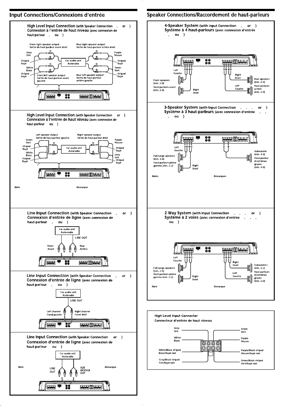
Make sure that the right speaker output from the
car audio unit is connected to the connector
marked “REAR” on the unit.
1 2 3
1 2 3
CC
CC
C
1 2 3
1 2 3
DD
DD
D
*
*
L R L R
FRON T R EAR
2
2
2 3
2 3
EE
EE
E
A C D
A C D
11
11
1
Pour plus de dé tails sur les ré glages des
commutateurs et commandes, reportez-vous à
« Emplacement et fonction des commandes ».
For details on the settings of switches and
controls, refer to “Location and Function of
Controls.”
A B C D E
A B
C D E
22
22
2
• In this system, the volume of the subwoofer will
be controlled by the car audio unit fader
control.
• In this system, the output signals to the
subwoofer are a combination of both the REAR
L and R INPUT jacks or the REAR high level input
connector signals.
• Dans ce systè me, le volume du haut-parleur
d’extrê mes graves est contrô lé par la commande
de balance avant/arriè re de l’autoradio.
• haut-parleur d’extrê mes graves sont constitué s
des signaux des prises REAR L et R INPUT ou des
signaux du connecteur d’entré e de haut niveau
REAR.
Pour plus de dé tails sur les ré glages des
commutateurs et commandes, reportez-vous à
« Emplacement et fonction des commandes ».
For details on the settings of switches and
controls, refer to “Location and Function of
Controls.”
A B C D E
A B C
D E
33
33
3
Pour plus de dé tails sur les ré glages des
commutateurs et commandes, reportez-vous à
« Emplacement et fonction des commandes ».
For details on the settings of switches and
controls, refer to “Location and Function of
Controls.”
Dans ce systè me, le volume des haut-parleurs
d’extrê mes graves est contrô lé par la commande
de balance avant/arriè re de l’autoradio.
In this system, the volume of the subwoofers will
be controlled by the car audio unit fader control.
Do not use when only
L and R is connected.
*
*
Ne pas utiliser lorsque
L et R uniquement
sont raccordé s.
R
E
M
+
1
2
V
G
N
D
#
#
#
#
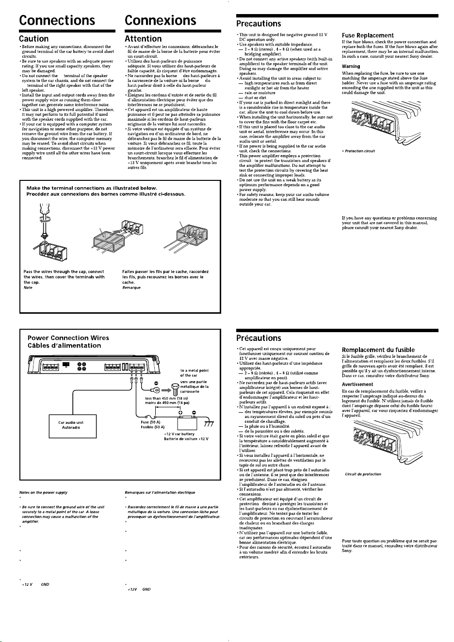
*
If you have the factory original or some other car audio unit without a remote output for the amplifier,
connect the remote input terminal (REMOTE) to the accessory power supply.
*
Si vous disposez du modè le d’origine ou d’un autre autoradio sans aucune sortie de commande à distance
pour l’amplificateur, raccordez la borne d’entré e de la commande à distance (REMOTE) à la prise
d’alimentation accessoires.
Connect the +12 V power supply wire only after all
the other wires have been connected.
Be sure to connect the remote control wire of the car
audio unit to the remote terminal.
• When using a car audio unit without a remote
output on the amplifier, connect the remote input
terminal (REMOTE) to the accessory power supply.
Use the power supply wire with a fuse attached
(50 A).
All power wires connected to the positive battery
post should be fused within 450 mm (18 in) of the
battery post, and before they pass through any
metal.
Make sure that the wires to be connected to the
and terminals of this unit are at least 10-
Gauge (AWG-10) or have a sectional area of more
than 5 mm
2
(
7
/
32
in
2
).
Raccordez le câ ble d’alimentation +12 V uniquement
aprè s avoir ré alisé toutes les autres connexions.
Veillez à raccordez le fil de commande à distance de
l’autoradio à la borne de commande à distance.
Si vous utilisez un autoradio dont l’amplificateur ne
comporte pas de sortie de commande à distance,
raccordez la borne d’entré e de commande à distance
(REMOTE) à la prise d’alimentation accessoires.
Utilisez un câ ble d’alimentation muni d’un fusible
(50 A).
Tous les fils é lectriques raccordé s au support de
batterie positif doivent ê tre proté gé s par un fusible à
une distance maximum de 450 mm (18 po) du
support de batterie et avant de passer dans une
partie mé tallique quelconque.
Assurez-vous que les câ bles à raccorder aux bornes
et de cet appareil sont d’un calibre d’au
moins 10 (AWG-10) ou d’une section supé rieure à
5 mm
2
(
7
/
32
po
2
).
Remote output
*
Sortie de
commande
*
(REM OUT)
R
E
M
+
1
2
V
G
N
D
3
3
When you tighten the screw, be careful not to
apply too much torque
*
as doing so may damage
the screw.
*
The torque value should be less than 1 N•m.
Lorsque vous vissez la vis, faites attention à ne
pas appliquer une trop grande force
*
, car cela
pourrait endommager la vis.
*
Le couple de torsion doit ê tre infé rieur à 1 N•m.
This amplifier is provided with a protection circuit
that operates in the following cases:
— when the unit is overheated
— when a DC current is generated
— when the speaker terminals are short-circuited
The PROTECTOR indicator lights up in red and the
unit will shut down.
If this happens, turn off the connected equipment,
take out the cassette tape or disc, and determine the
cause of the malfunction. If the amplifier has
overheated, wait until the unit cools down before
use.
*
Cet amplificateur est é quipé d’un circuit de
protection qui s’active dans les cas suivants :
— surchauffe de l’appareil,
— production d’un courant continu,
— court-circuit aux bornes des haut-parleurs.
L’indicateur PROTECTOR s’allume en rouge et
l’appareil s’arrê te.
Si le cas se pré sente, é teignez tout appareil raccordé
et é jectez la cassette ou le disque compact avant
d’examiner la cause de la dé faillance. Si
l’amplificateur a surchauffé , attendez qu’il
refroidisse.
*
*
1 2 3
1 2 3
AA
AA
A
2 3
2 3
BB
BB
B
Assurez-vous que la sortie du haut-parleur droit de
l’autoradio est raccordé e au connecteur portant
l’indication « REAR » sur l’appareil.
Make sure that the right speaker output from the
car audio unit is connected to the connector
marked “REAR” on the unit.
1 2 3
1 2 3
CC
CC
C
1 2 3
1 2 3
DD
DD
D
*
*
L R L R
FRON T R EAR
2
2
2 3
2 3
EE
EE
E
A C D
A C D
11
11
1
Pour plus de dé tails sur les ré glages des
commutateurs et commandes, reportez-vous à
« Emplacement et fonction des commandes ».
For details on the settings of switches and
controls, refer to “Location and Function of
Controls.”
A B C D E
A B
C D E
22
22
2
• In this system, the volume of the subwoofer will
be controlled by the car audio unit fader
control.
• In this system, the output signals to the
subwoofer are a combination of both the REAR
L and R INPUT jacks or the REAR high level input
connector signals.
• Dans ce systè me, le volume du haut-parleur
d’extrê mes graves est contrô lé par la commande
de balance avant/arriè re de l’autoradio.
• haut-parleur d’extrê mes graves sont constitué s
des signaux des prises REAR L et R INPUT ou des
signaux du connecteur d’entré e de haut niveau
REAR.
Pour plus de dé tails sur les ré glages des
commutateurs et commandes, reportez-vous à
« Emplacement et fonction des commandes ».
For details on the settings of switches and
controls, refer to “Location and Function of
Controls.”
A B C D E
A B C
D E
33
33
3
Pour plus de dé tails sur les ré glages des
commutateurs et commandes, reportez-vous à
« Emplacement et fonction des commandes ».
For details on the settings of switches and
controls, refer to “Location and Function of
Controls.”
Dans ce systè me, le volume des haut-parleurs
d’extrê mes graves est contrô lé par la commande
de balance avant/arriè re de l’autoradio.
In this system, the volume of the subwoofers will
be controlled by the car audio unit fader control.
Do not use when only
L and R is connected.
*
*
Ne pas utiliser lorsque
L et R uniquement
sont raccordé s.
R
E
M
+
1
2
V
G
N
D
#
#
#
#
*
If you have the factory original or some other car audio unit without a remote output for the amplifier,
connect the remote input terminal (REMOTE) to the accessory power supply.
*
Si vous disposez du modè le d’origine ou d’un autre autoradio sans aucune sortie de commande à distance
pour l’amplificateur, raccordez la borne d’entré e de la commande à distance (REMOTE) à la prise
d’alimentation accessoires.
Connect the +12 V power supply wire only after all
the other wires have been connected.
Be sure to connect the remote control wire of the car
audio unit to the remote terminal.
• When using a car audio unit without a remote
output on the amplifier, connect the remote input
terminal (REMOTE) to the accessory power supply.
Use the power supply wire with a fuse attached
(50 A).
All power wires connected to the positive battery
post should be fused within 450 mm (18 in) of the
battery post, and before they pass through any
metal.
Make sure that the wires to be connected to the
and terminals of this unit are at least 10-
Gauge (AWG-10) or have a sectional area of more
than 5 mm
2
(
7
/
32
in
2
).
Raccordez le câ ble d’alimentation +12 V uniquement
aprè s avoir ré alisé toutes les autres connexions.
Veillez à raccordez le fil de commande à distance de
l’autoradio à la borne de commande à distance.
Si vous utilisez un autoradio dont l’amplificateur ne
comporte pas de sortie de commande à distance,
raccordez la borne d’entré e de commande à distance
(REMOTE) à la prise d’alimentation accessoires.
Utilisez un câ ble d’alimentation muni d’un fusible
(50 A).
Tous les fils é lectriques raccordé s au support de
batterie positif doivent ê tre proté gé s par un fusible à
une distance maximum de 450 mm (18 po) du
support de batterie et avant de passer dans une
partie mé tallique quelconque.
Assurez-vous que les câ bles à raccorder aux bornes
et de cet appareil sont d’un calibre d’au
moins 10 (AWG-10) ou d’une section supé rieure à
5 mm
2
(
7
/
32
po
2
).
Remote output
*
Sortie de
commande
*
(REM OUT)
R
E
M
+
1
2
V
G
N
D
3
3
When you tighten the screw, be careful not to
apply too much torque
*
as doing so may damage
the screw.
*
The torque value should be less than 1 N•m.
Lorsque vous vissez la vis, faites attention à ne
pas appliquer une trop grande force
*
, car cela
pourrait endommager la vis.
*
Le couple de torsion doit ê tre infé rieur à 1 N•m.
This amplifier is provided with a protection circuit
that operates in the following cases:
— when the unit is overheated
— when a DC current is generated
— when the speaker terminals are short-circuited
The PROTECTOR indicator lights up in red and the
unit will shut down.
If this happens, turn off the connected equipment,
take out the cassette tape or disc, and determine the
cause of the malfunction. If the amplifier has
overheated, wait until the unit cools down before
use.
*
Cet amplificateur est é quipé d’un circuit de
protection qui s’active dans les cas suivants :
— surchauffe de l’appareil,
— production d’un courant continu,
— court-circuit aux bornes des haut-parleurs.
L’indicateur PROTECTOR s’allume en rouge et
l’appareil s’arrê te.
Si le cas se pré sente, é teignez tout appareil raccordé
et é jectez la cassette ou le disque compact avant
d’examiner la cause de la dé faillance. Si
l’amplificateur a surchauffé , attendez qu’il
refroidisse.
*
*