INSTRUCTION MANUAL
E
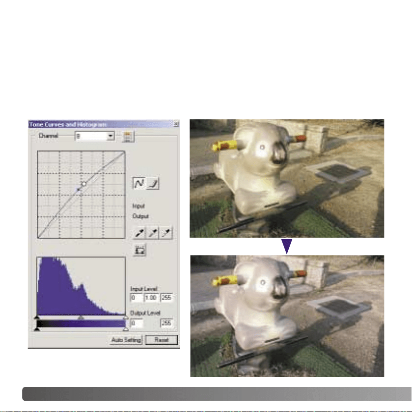
2 EXAMPLES
By selecting individual color channels on the tone curve, adjustments to the overall color
of an image can be made. If the image is too red, green, or blue, simply drag the
corresponding color-channel curve down until the color appears natural. If the color cast
is predominantly one of the secondary colors, cyan, magenta, or yellow, move the curve
of the complementary color up. In this example, the image is too yellow. By moving the
blue curve up, the image looks more neutral. For more on tone-curve corrections, see
page 50.
TONE-CURVE CORRECTIONS

3
BEFORE YOU BEGIN
Before installing the DiMAGE Viewer software, read the data-transfer section in the
camera manual. This section details how to connect the camera to a computer using the
supplied USB cable. The examples in this manual assume the camera is connected to
the computer with a USB cable as described in the camera manual.
This instruction manual does not provide instruction in the basic operation of the personal
computers, or the basic operation of Windows or Macintosh operating systems; refer to
the manuals supplied with the computer.
The examples in this manual use Windows software. The appearance of the screens may
differ from the examples when using Macintosh or other Windows operating systems.
Every precaution has been taken to ensure the accuracy of this material. Contact Minolta
if you have any questions. Minolta is not responsible for any loss or damage caused by
the use of this software.
This instruction manual may not be copied either in part or in its entirety without the prior
permission of Minolta.
TABLE OF CONTENTS
System requirements .............................................................................................................................6
DiMAGE Viewer system requirements......................................................................................6
QuickTime system requirements...............................................................................................7
Before installing the DiMAGE Viewer........................................................................................7
Installation ......................................................................................................................................8
Installing the DiMAGE Viewer - Windows.................................................................................8
Installing the DiMAGE Viewer - Macintosh .............................................................................10
Starting up the Viewer..........................................................................................................................12
Starting up the Viewer - Windows...........................................................................................12
Starting up the Viewer - Macintosh.........................................................................................13
Importing and editing images...............................................................................................................14
Loading image files..................................................................................................................14
Updating the thumbnail window ..............................................................................................14
Opening audio files..................................................................................................................15

4 TABLE OF CONTENTS
Changing the display format....................................................................................................16
Changing the thumbnail format...............................................................................................17
Sorting image files...................................................................................................................18
Selecting thumbnails ...............................................................................................................18
Renaming single files ..............................................................................................................19
Renaming multiple files ...........................................................................................................19
Creating folders.......................................................................................................................20
Moving images to another folder.............................................................................................21
Copying images to another folder ...........................................................................................22
Cut, copy, paste, and delete - Windows..................................................................................23
Cut, copy, paste, and delete - Macintosh................................................................................23
Displaying and saving image information................................................................................24
Image information setup..........................................................................................................25
Editing the subject line ............................................................................................................25
Basic image processing .......................................................................................................................26
Image-correction window.........................................................................................................26
Tool bars .....................................................................................................................27
Displaying images in the image-correction window ................................................................28
Flip and rotate images.............................................................................................................29
Controlling the image display..................................................................................................30
Fit-to-window button ...................................................................................................30
Resizing the viewer window .......................................................................................30
Grab tool.....................................................................................................................31
Magnifying tool............................................................................................................31
Menu options..............................................................................................................31
Variation palette.......................................................................................................................32
Brightness, contrast, and color-balance palette......................................................................33
An introduction to color............................................................................................................35
Comparing pre- and post correction images...........................................................................36
Undoing and redoing an image correction..............................................................................37
Processing images of text and line art ...................................................................................37
Data imprinting ........................................................................................................................38
Saving images ....................................................................................................................................40
Resizing an image to be saved...............................................................................................40
Saving an image......................................................................................................................40
Changing the image name or format.......................................................................................41
Printing ....................................................................................................................................42
Creating an index sheet ..........................................................................................................44
Advanced image processing................................................................................................................46
The tone curve / histogram palette..........................................................................................47

5
Using the tone curve ...............................................................................................................48
Drawing tone curves by freehand............................................................................................49
A short guide to tone-curve corrections...................................................................................50
White, black, and gray-point corrections.................................................................................52
Setting the white and black-point values.................................................................................54
Tone-curve / histogram auto setting........................................................................................55
Displaying the color histograms ..............................................................................................55
Histogram corrections..............................................................................................................56
A short guide to histogram corrections....................................................................................58
Hue, saturation, and lightness palette.....................................................................................60
Auto-setting button......................................................................................................61
Sharpness................................................................................................................................62
Area marquee - saving or printing a portion of an image........................................................64
Tracking image corrections - snapshot button ........................................................................65
Saving image corrections........................................................................................................66
Loading image-correction Jobs ...............................................................................................67
Processing RAW images.........................................................................................................68
Saving RAW images................................................................................................................70
Saving RAW Jobs....................................................................................................................71
Loading RAW Jobs..................................................................................................................71
Batch processing.....................................................................................................................72
Movie Enhancer ...................................................................................................................................74
Flicker correction.....................................................................................................................75
Editing movie files....................................................................................................................76
Splicing two movie clips..............................................................................................76
Copying sections from movie to another....................................................................77
Correcting movie images.........................................................................................................78
Advanced setup....................................................................................................................................80
Customizing the viewer - Preferences.....................................................................................80
Color matching - Color preferences ........................................................................................82
Using printer ICC profiles........................................................................................................84
Using monitor ICC profiles ......................................................................................................85
About DiMAGE Viewer ICC profiles........................................................................................85
ICC profile locations ................................................................................................................86
Viewer notes ....................................................................................................................................87
Uninstalling the DiMAGE Viewer.............................................................................................87
Copying Job files.....................................................................................................................88
Embedded camera color profiles.............................................................................................90
Note on color measurement....................................................................................................90
Hue correction example...........................................................................................................91

Apple Macintosh series computersIBM PC/AT compatible computers
6 SYSTEM REQUIREMENTS
PowerPC 100MHz or higher
128MB or more of available RAM
200MB or more of available hard-disk
space
A 24-bit color or greater monitor with a
minimum resolution of 800 X 600. 1024
X 768 or higher is recommended.
DIMAGE VIEWER SYSTEM REQUIREMENTS
Refer to the DiMAGE Viewer CD-ROM for Windows and Macintosh operating system
requirements. The requirements are printed on the CD-ROM disk. Compatibility with
Windows XP is with the Home or Professional editions only.
Computers with Windows 98 operating systems require Microsoft Internet Explorer 5.0 or
later.
133MHz Pentium processor or higher
64MB or more of RAM
(128MB or more with Windows XP)
200MB or more of available hard-disk
space
A True Color (24 bit) or greater monitor
with a minimum resolution of 800 X
600. 1024 X 768 (XGA) or higher is
recommended.
CD-ROM drive
QuickTime 5 or later QuickTime 4 or later

7
RAM-stationed programs such as anti-virus or installation-monitoring software may cause
the installer to fail. Remove or disable these programs before installing the DiMAGE
Viewer. Reinstall or enable the software when the installation is complete.
If you are upgrading the DiMAGE Viewer from a version earlier than 2.2, see page 88 on
how to save any Job file which may have been created. The procedure must be
completed before installing the new Viewer version.
BEFORE INSTALLING THE DiMAGE VIEWER
QUICKTIME SYSTEM REQUIREMENTS
IBM PC / AT Compatible
Pentium-based computer
Windows 95, 98, 98SE, NT, Me,
2000 Professional, or XP.
32MB or more of RAM
Sound Blaster or compatible sound card
DirectX 3.0 or later recommended
To install QuickTime, follow the instructions in
the installer. In the window to choose the type
of installation, select the recommended
option; the minimum or custom options may
prevent the DiMAGE Viewer from operating
properly.
Macintosh users can download the latest
version of QuickTime free of charge from the
Apple Computer web site: www.apple.com.
8
INSTALLING THE
DiMAGE VIEWER - WINDOWS
In the example below, the hard disk drive is drive F. The letters designating the drives will
vary between computers. With Windows 2000 or XP, the software should be installed with
the Administrator privilege.
Turn on the computer to start Windows.
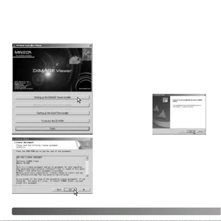
Insert the DiMAGE Viewer CD-ROM into the CD-
ROM drive. The DiMAGE Viewer Installer window
will open automatically. The installer window varies
with the camera model.
Click the “Starting up the DiMAGE Viewer installer”
button to begin installation.
The welcome window
will open. Click “Next>”
to continue.
The license agreement appears. If you accept the
agreement, click “Yes” to continue the installation
routine.
Read the entire license agreement carefully before
continuing. If you do not agree to the terms, click
“No” to exit the installation program.
INSTALLATION
9
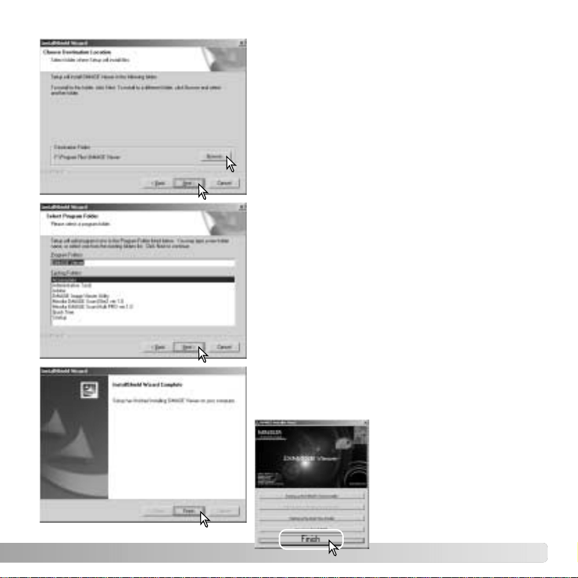
To install the software in the default location -
F:\Program Files\DiMAGE Viewer, click “Next >.”
To install the software in a different location, click
browse button to display the folder selection
window. Specify the directory in which to install the
software.
The name of the default program folder is
displayed. To install the software icons in this
folder, click “Next>.” Installation will begin.
To install the software icons in another folder,
select one of the folders listed in the existing-
folders box below. Click “Next>” to begin
installation.
When the software installation has been
completed, a message will be displayed. Click
“Finish.”
The DiMAGE Viewer
installer window will be
displayed. Click “Finish” to
close the window.
10 INSTALLATION
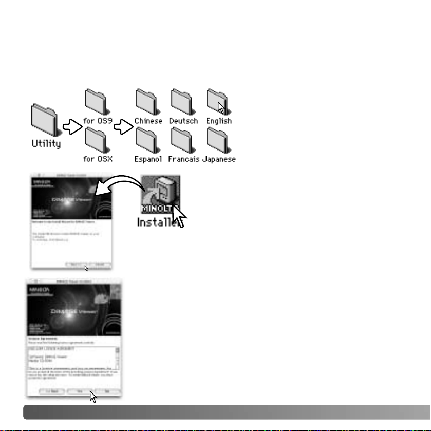
The license agreement appears. If you accept the agreement,
click “Yes” to continue the installation routine.
Read the entire license agreement carefully before continuing.
If you do not agree to the terms, click “No” to exit the installation
program.
Turn on the computer to start the operating system. When the desktop appears, insert the
DiMAGE Viewer CD-ROM into the CD-ROM drive. The contents of the CD-ROM appear
automatically. If the contents do not appear, double-click the CD-ROM icon to open it.
INSTALLING THE
DiMAGE VIEWER - MACINTOSH
Open the utility folder, and then open
the appropriate operating system and
language folder.
Double-click on the installer icon to start the
Installation program.
When the installation screen appears click “Next>” to begin the
setup.
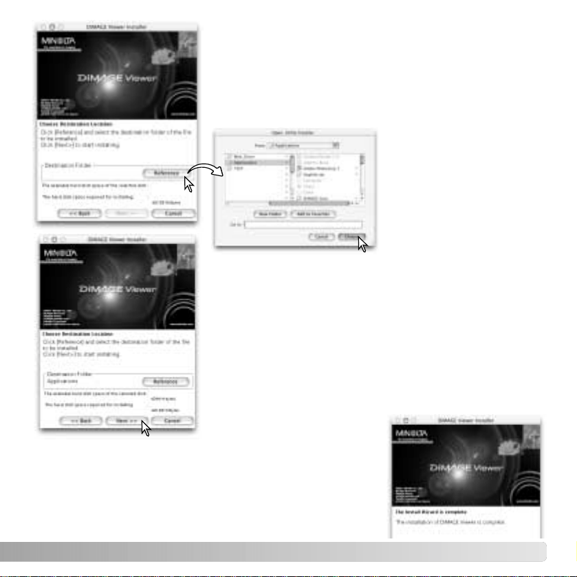
11
The location for the DiMAGE Viewer files must be specified.
Click the reference button.
Confirm the installation location on the installer screen. Click
“Next >>” to install the DiMAGE Viewer.
A window will appear when the software has been installed.
Click “Finish” to exit the installer.
Using the folder-selection
dialog box, select the
location where the software
should be installed. Click
“Choose.”
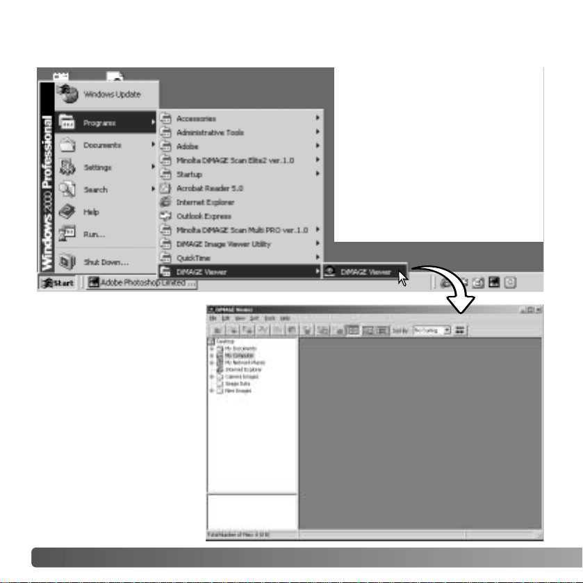
12 STARTING UP THE VIEWER
STARTING UP THE VIEWER
- WINDOWS
Select the DiMAGE Viewer from
the DiMAGE Viewer folder in
the program option of the start
menu.
The utility will start up
and the thumbnail win-
dow will be displayed.
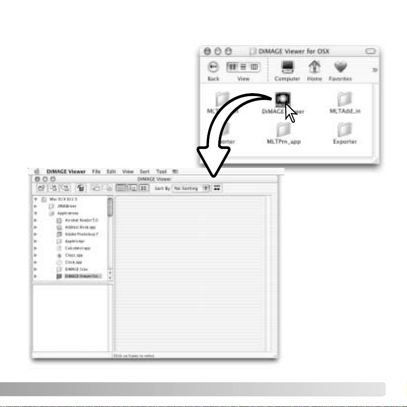
13
STARTING UP THE VIEWER
- MACINTOSH
Open the DiMAGE Viewer folder.
Double-click the DiMAGE Viewer icon to
start up the application. The main
window of the utility will be displayed.
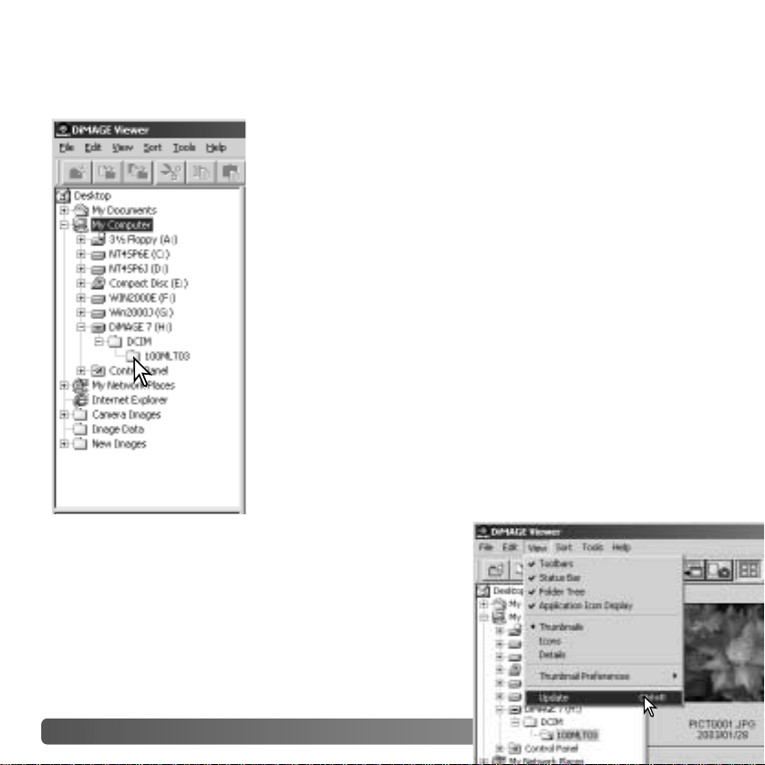
14 IMPORTING AND EDITING IMAGES
Images can be loaded directly from a digital camera or from
image folders saved in the computer. Simply use the folder
tree to select the file containing the images. For information
on the camera’s folder organization, and connecting the
camera to the computer, refer to the camera’s instruction
manual.
Click on the positive (+) nodes to display the contents of a
folder. Click on a negative (–) node to hide the folder
contents.
Click on the image folder to load the images. All still-image,
audio, and movie files in the folder will be loaded.
LOADING IMAGE FILES
UPDATING THE THUMBNAIL WINDOW
If any changes are made to the folder tree or thumbnail
display, for example, the camera is disconnected from
the computer, the window can be updated. Select the
update option from the view menu to update the
DiMAGE Viewer.
IMPORTING AND EDITING IMAGES
15
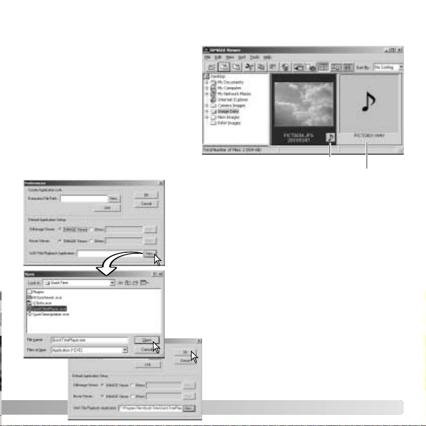
OPENING AUDIO FILES
Voice memos, audio captions, and audio
recordings made with the camera can
be played back with the DiMAGE
Viewer. To confirm if your camera can
make audio recordings, refer to the
instruction manual. After setting up the
preferences box (see below), simply
click on the note button or double click
on the audio file to play back the
recordings.
Voice memo / Audio caption
Audio recording
To set up the Viewer to play back audio files, select the
preferences option from the file menu to open the
dialog box.
Click on the view button next to the WAV file playback
application text box to display the open dialog box.
Locate the application to play back audio files;
QuickTime or the Windows Media Player can be used
for playback. Click the open button; the execution path
will be displayed in the preferences window.
Click the OK button in the preferences
window to complete the operation.
16 IMPORTING AND EDITING IMAGES
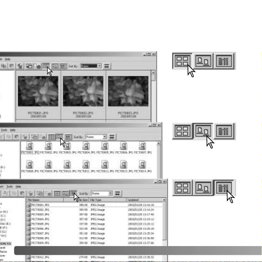
CHANGING THE DISPLAY FORMAT
The contents of a folder can be displayed as thumbnail images, icons, or in a list with file
data. To change the display format, simply press the appropriate button located on the
tool bar.
Thumbnail display button
Icon display button
List display button
17
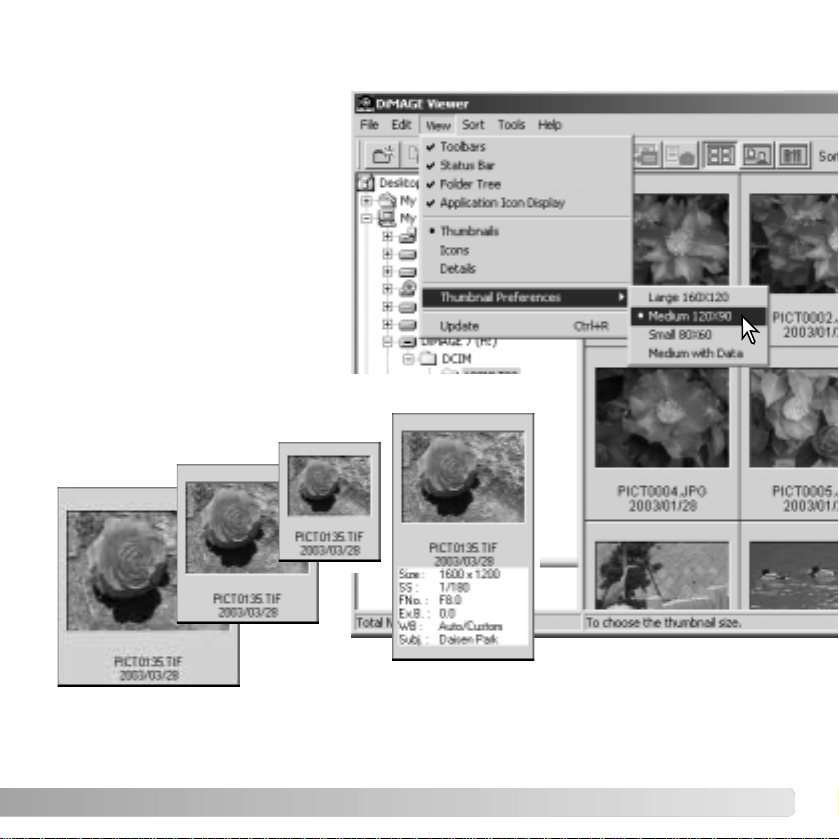
CHANGING THE THUMBNAIL FORMAT
The thumbnail format can be
changed. Four format are
available: large, medium, small,
and medium with data.
To change the format, highlight
the Thumbnail Preferences option
on the view menu to display the
format options. Highlight and click
the desired thumbnail format; the
thumbnail display will change
accordingly.
Large
Medium
Small
Medium with data
To edit or add a
subject line in
the data display
see page 25.
18 IMPORTING AND EDITING IMAGES
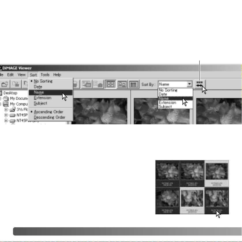
SORTING IMAGE FILES
Image files can be sorted by name, date, extension, or subject line in ascending or
descending order. This function works with the thumbnail, icon, or list displays (p. 16). To
sort the displayed images, use the sort menu or the sort-by drop-down menu on the tool
bar. Simply highlight the sorting category with the mouse.
The sort menu can also be used to change the display between ascending and
descending order. The reverse-order button on the tool bar will also change the display
order.
Reverse-order button
SELECTING THUMBNAILS
Click on the thumbnail boarders or file icon to select a
single image. To select multiple images, press and hold
the control key (Windows) or command key (Macintosh)
and then click on each image; the selected frames will
have a dark border. To deselect an image, click on the
thumbnail or icon a second time while holding the control
key (Windows) or command key (Macintosh). To select
consecutive images, press and hold the shift key and
then click on the first and last image of the series. Press
the control key (Windows) or command key (Macintosh)
and “A” key at the same time to select all images.
19
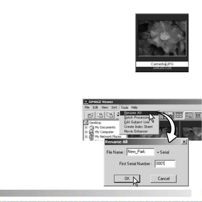
RENAMING MULTIPLE FILES
Multiple files can be renamed in the thumbnail, icon, or list displays (p. 16). Click on the
thumbnail boarders or file icon to select the images to be renamed (p. 18).
From the tool menu, select the
rename-all option. The rename-
all window will open.
In the rename-all window, enter the new file
name up to ten characters, and enter the
first serial number up to five digits.
Click the OK button to change the file
names of the selected images.
RENAMING SINGLE FILES
Single files can be renamed in the thumbnail, icon, or list
displays (p. 16). When rewriting file names, always include
the original file extension.
Click on the thumbnail, icon, or file name to highlight it.
Click on the file name to activate the cursor or select rename
from the edit menu. Use the keyboard to change the file
name.
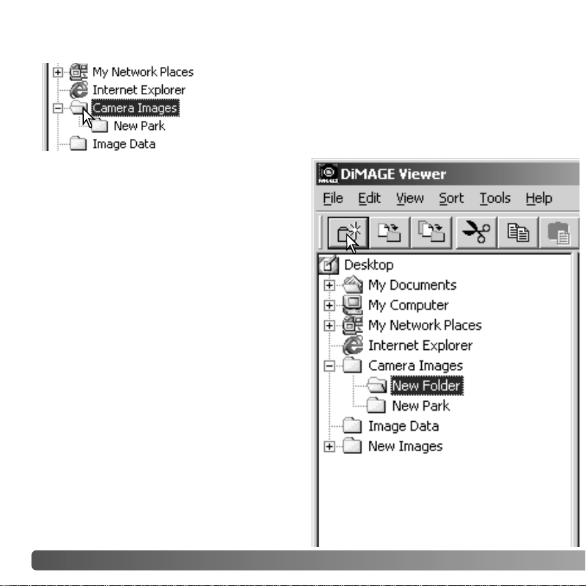
20 IMPORTING AND EDITING IMAGES
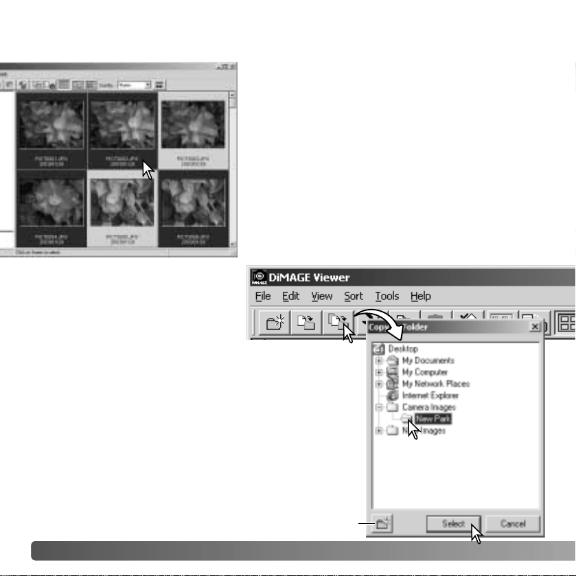
New folders can be created to store images. Click on the
desired location for the new folder. In this example the new
folder will be placed in Camera Images.
Click on the new-folder button on the tool bar
or select new folder from the file menu. The
new folder will be created in the specified
location.
The folder name can be changed with the
keyboard.
CREATING FOLDERS
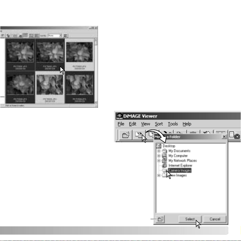
MOVING IMAGES TO ANOTHER FOLDER
Multiple files can be moved from one folder to
another. Click on the thumbnail boarders or file icon
to select the images to be moved.
• To select multiple images, press and hold the control
key (Windows) or command key (Macintosh) and then
click on each image to be moved; the selected frames
will have a dark border. To deselect an image, click on
the thumbnail or icon a second time while holding the
control key (Windows) or command key (Macintosh).
To select consecutive images, press and hold the shift
key and then click on the first and last image of the
series. Press the control key (Windows) or command
key (Macintosh) and “A” key at the same time to select
all images.
Click on the move-to-folder button on
the tool bar or select the move-to-folder
option from the edit menu. The move-
to-folder window will open.
In the move-to-folder window, click on the destination
folder. Click the select button to move the specified
images to the designated folder. If an image has an
attached audio, or thumbnail file, those files will also be
copied.
A new folder can be created in this window. Click on the
location for the new folder and click the new-folder
button; a folder will appear in the folder tree in the
window. The folder can be renamed.
New-folder button
21
22 IMPORTING AND EDITING IMAGES
COPYING IMAGES TO ANOTHER FOLDER
Multiple files can be copied from one folder to
another. Click on the thumbnail boarders or file icon
to select the images to be copied.
• To select multiple images, press and hold the control
key (Windows) or command key (Macintosh) and then
click on each image to be copied; the selected frames
will have a dark border. To deselect an image, click on
the thumbnail or icon a second time while holding the
control key (Windows) or command key (Macintosh).
To select consecutive images, press and hold the shift
key and then click on the first and last image of the
series. Press the control key (Windows) or command
key (Macintosh) and “A” key at the same time to select
all images.
Click on the copy-to-folder button
on the tool bar or select the copy-
to-folder option from the edit menu.
The copy-to-folder window will
open.
In the copy-to-folder window, click on the destination
folder. Click the select button to copy the specified
images to the designated folder If an image has an
attached audio, or thumbnail file, those files will also be
copied.
A new folder can be created in this window. Click on the
location for the new folder and click the new-folder
button; a folder will appear in the folder tree in the
window. The folder can be renamed.
New-folder button
23
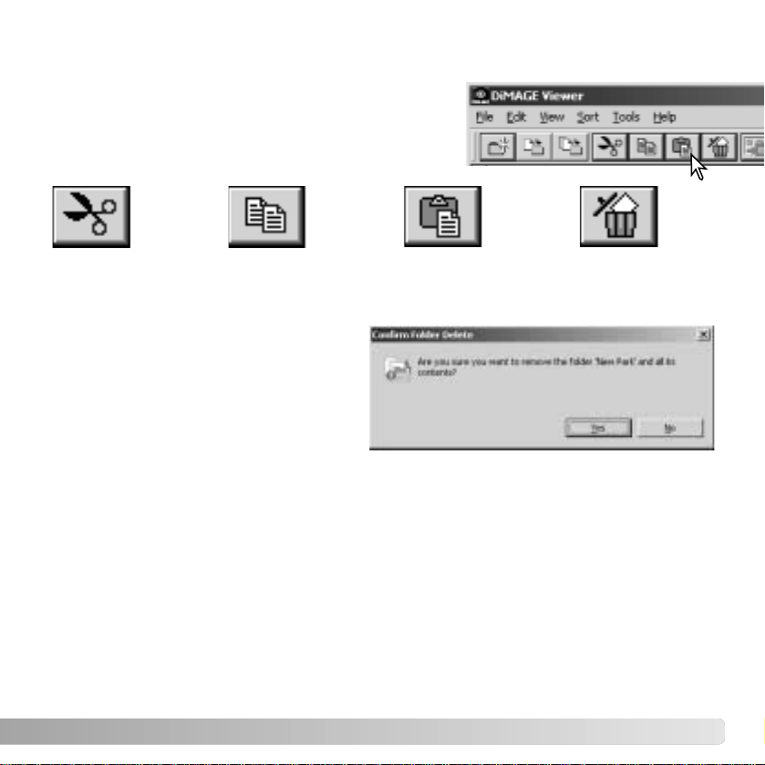
CUT, COPY
, PASTE, AND DELETE - WINDOWS
When a delete command is given, a
confirmation screen will appear. Clicking
the yes button will execute the command
and delete the data, clicking the no
button will cancel the delete command.
Cut Copy Paste Delete
Select the folder or images to be moved. Click the cut or copy button. The display will not
change when a cut is made until the paste has been completed. Click on the new location
for the folder or images. Click the paste button to complete the operation.
The cut, copy, and paste functions are located in the edit menu. They can be used for
editing file and folder names, but they cannot be used to cut, copy, or paste files and
folders.
The delete button on the tool bar or pressing the command and delete button on the
keyboard will erase files and folders. When a delete command is given, a confirmation
screen will appear. Clicking the yes button will execute the command and delete the data,
clicking the no button will cancel the delete command.
CUT
, COPY, PASTE, AND DELETE - MACINTOSH
The tool bar and edit menu can be used to cut, copy,
paste, and delete folders and single or multiple
images. These functions affect any audio or thumbnail
files attached to an image. The delete key on the
keyboard will also delete folders and images.
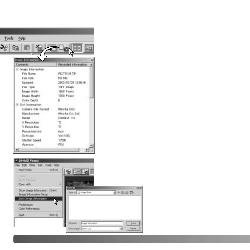
Image information can be saved as a special text file.
Simply select single or multiple thumbnails and then
select the save-image-information option from the file
menu; the save-as dialog box will open.
The image-information file can be
opened in spreadsheet software
such as Microsoft Excel or with
word processing application like
Simple Text.
24
DISPLAYING AND SAVING IMAGE INFORMATION
With an image selected in the thumbnail window, click
the image-information button. If more than one
thumbnail image is selected, one window for each image
will open.
To close the window, click the close button in the top
right corner. The information displayed in the window
may vary between camera models.
Recording data is contained in an exif tag attached to
the image file. If an image is opened in a image-
processing application that does not support exif tag
data, and then the image is saved overwriting the
original data, the exif tag information will be erased.
When using software other than the DiMAGE Viewer,
always rename the image file to protect the exif tag
data.
IMPORTING AND EDITING IMAGES
25
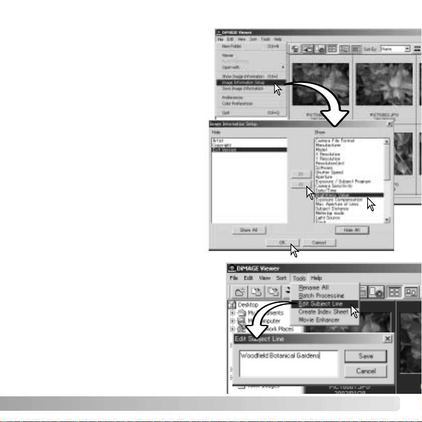
IMAGE INFORMATION SETUP
The Exif information displayed in the image
information window can be edited. Select
the image-information-setup option from
the file menu to open the setup window.
Click on the item to be added to or
removed from the image information
display and click the appropriate move
button.
>>: to move to the show list.
<<: to move to the hide list.
The show-all and hide-all buttons adds or
removes all Exif information in the image-
information display.
Click “OK” to save the setup.
EDITING THE SUBJECT LINE
Cameras like the DiMAGE A1 can attach text
to an image’s Exif data. This is shown in the
subject field in the image-information display.
Exif 2.1 or later format images can have a
subject line added or edited.
Select the image(s) to be edited. Choose the
edit-subject-line option from the tool menu to
open the edit window. Enter the subject line
and click the save button to complete the
operation.
26 BASIC IMAGE PROCESSING
BASIC IMAGE PROCESSING
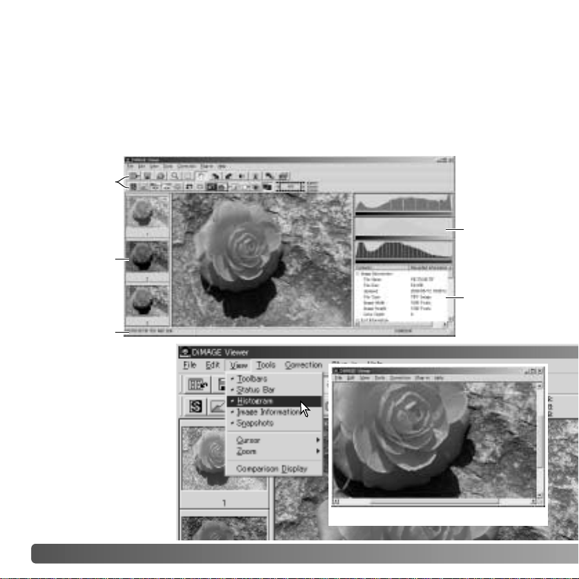
The image-correction window displays the utility’s image-processing tools. Adjustments to
color, contrast, brightness, and saturation can be made. This section contains details on
the basic image-processing tools. For descriptions of the advanced tools, see pages 46
though 73.
IMAGE-CORRECTION WINDOW
Tool bars
Status bar
Color
histogram
display
Image
information
display
(p. 25)
The view menu can
turn the tool bars,
snapshot display area,
status bar, image
information display,
and color histograms
on and off. Simply
choose the menu
option to show or hide
the display.
Snapshot
display area
(p. 65)
Image display area
Image display area only

27
Brightness, contrast, and color-balance button (p. 33)
Image number
display (p. 28)
Fit-to-window button
(p. 30)
Reset-all button (p. 37)
Redo button (p. 37)
Undo button (p. 37)
Variation button (p. 32)
Tool bars
Magnifying button (p. 31)
Grab button (p. 31)
Index-display button (p. 28)
Flip-vertical button (p. 29)
Flip-horizontal button (p. 29)
Rotate-left button (p. 29)
Rotate-right button (p. 29)
Comparison-display button (p. 36)
Data-imprinting button
(p. 38)
28 BASIC IMAGE PROCESSING
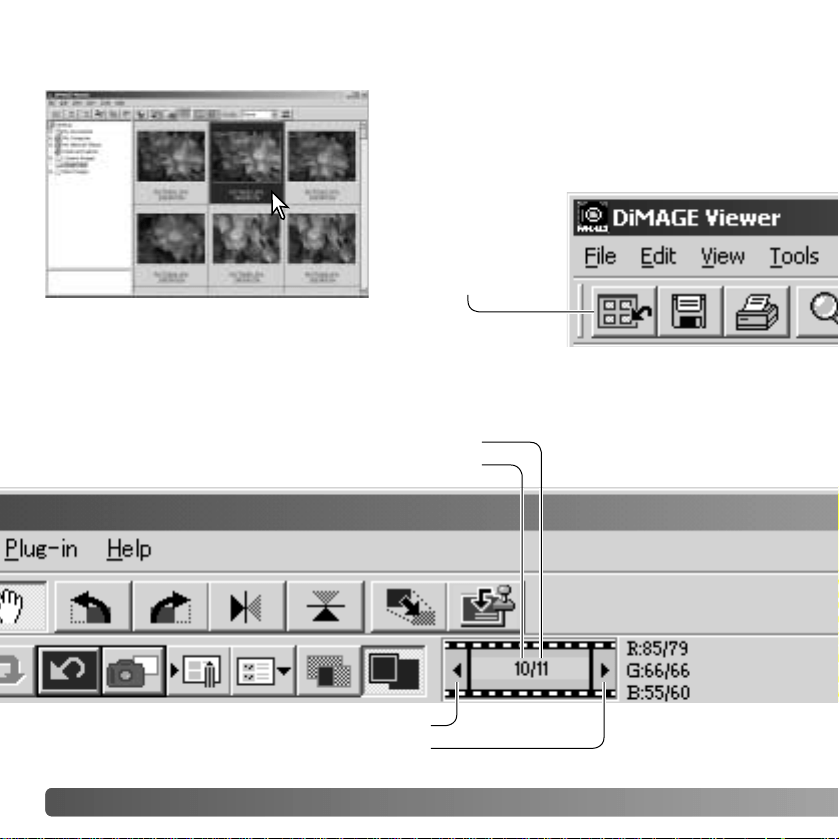
In the index display, an image can automatically
be loaded into the image-correction window.
Simply double-click on a thumbnail or icon to
display the image in the image-correction
window.
The color-correction window will display the image number and the total number of
images loaded. Clicking on the arrows on each side of the display will load the previous
or next image.
Image number of the image currently displayed
Total number of images loaded in the utility
DISPLAYING IMAGES IN THE IMAGE
-CORRECTION WINDOW
Click to display the previous image
Click to display the next image
To return to the index
display, click the
index-display button.
29
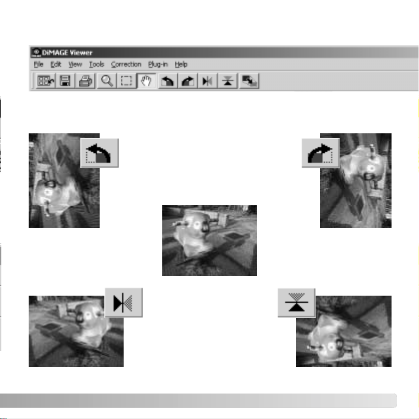
FLIP AND ROTATE IMAGES
Original image
Flip - when an image is
flipped, it will create a mirror
image.
Rotate - the rotate-right button rotates
the thumbnail 90° clockwise and the
rotate-left button rotates the thumbnail
90° counterclockwise each time the
buttons are clicked.
The orientation of the displayed image can be changed with the flip and rotate buttons
on the tool bar or with the tool menu. Any changes to image orientation will be applied to
the thumbnail image in the index display.
30 BASIC IMAGE PROCESSING
Normally, an image is displayed based on its size and resolution. When the
image is too large for the display area, clicking the fit-to-window button will
automatically resize the image to fit the display area. Clicking the button again
displays the image at its original size. The grab and zoom tool cannot be used with the
fit-to-window function.
CONTROLLING THE IMAGE DISPLAY
Fit-to-window button
Resizing the viewer window
The utility window can be resized by clicking and dragging the bottom right corner. If the
fit-to-window function is active, the displayed image will automatically adjust to fit the
display area.
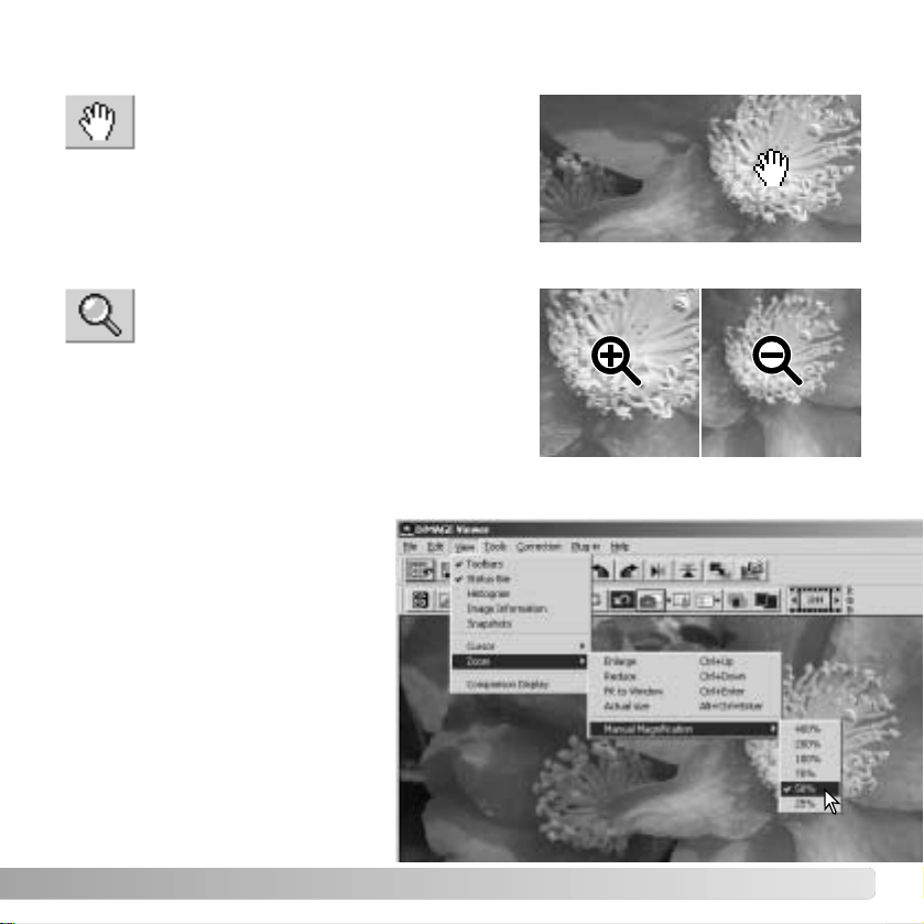
31
The display image can be enlarged or
reduced. Click the magnifying button on
the tool bar or select Magnifying Tool from
the cursor option on the view menu. Click on the
image to enlarge. To reduce, hold down the shift
(Windows) or option key (Macintosh) and click on
the image. When the image has reached the
magnification limit, the plus or minus sign in the
magnifying icon will disappear.
When an image is larger than the display
area, the grab tool can be used to scroll
the image. Click the grab button on the tool
bar or select Grab Tool from the cursor option on
the view menu. Click and drag on the image to
scroll.
Grab tool
Magnifying tool
Enlarge Reduce
Menu options
The zoom option on the view menu
controls the size of the display
image. As well as the magnifying
tool’s enlarge and reduce functions
and fit-to-window function, the
menu can display the image at
actual size or at preset
magnifications. The tool bar, status
bar, histogram, image information,
and snapshot display areas can be
hidden or shown by selecting the
appropriate option on the menu.
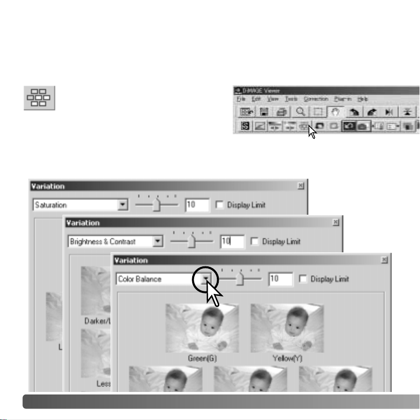
32
The variation palette allows an image to be corrected by comparing it to other slightly
corrected images surrounding it. This is an easy method to correct images for individuals
who are inexperienced in image processing or photofinishing.
Click the arrow next to the variation list box to select the image quality to be corrected:
color balance, brightness and contrast, or saturation. Each variation palette shows the
current image in the center with corrected samples displayed around it.
VARIATION PALETTE
Click the variation button or select
Variation from the image-correction
option on the correction menu to display
the palette.
BASIC IMAGE PROCESSING
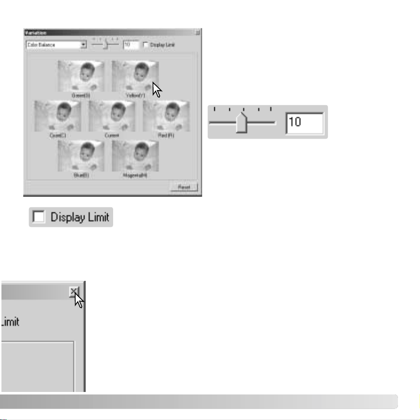
Checking the display-limit check box will indicate when any of the image values exceed
0 (black limit) or 255 (white limit) with the complementary color. For example, if the blue
area of the image exceeds those values, the limit is displayed with the complementary
color, yellow.
33
Click the best image among the frames. The
selected image becomes the new center
surrounded by a set of new images and the
change is applied to the prescan image. This
procedure can be repeated until the desired
correction is obtained. Click the reset button
to cancel all changes.
Click the close button to close the palette to apply any image corrections.
The difference between the samples can be
changed. Drag the variation-step slider, or
enter a value into the text box to set the
degree of correction. The initial setting is 10.
The correction step can be set between 1
and 20.
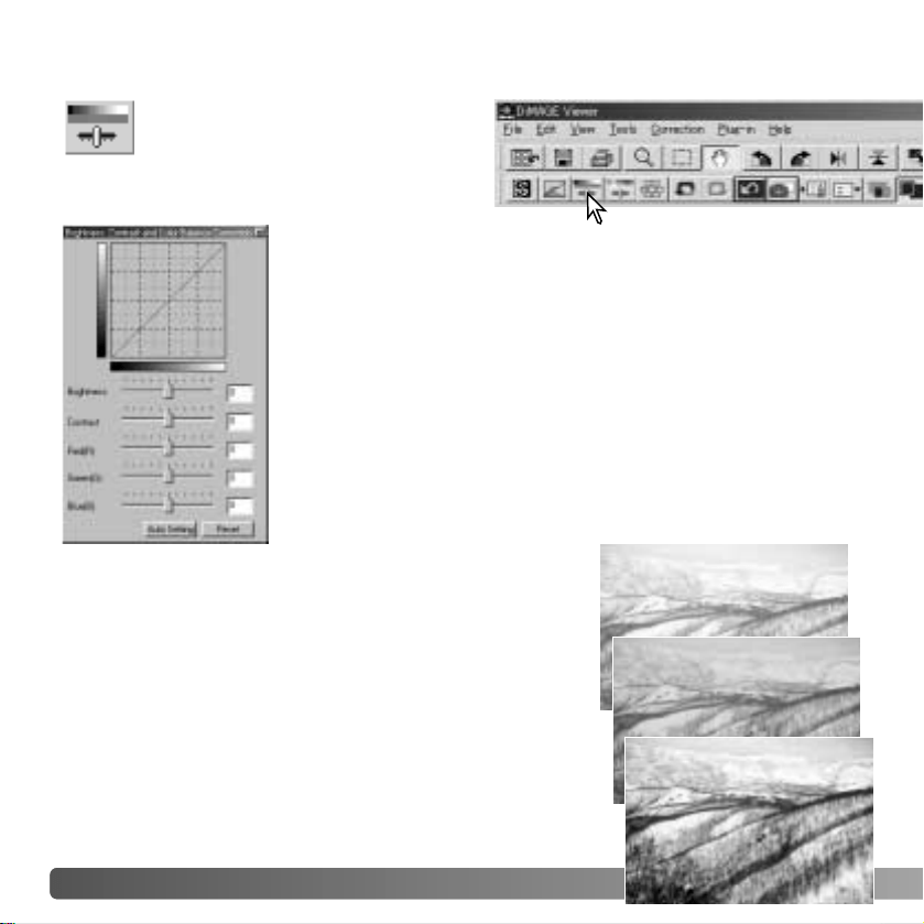
34 BASIC IMAGE PROCESSING
BRIGHTNESS, CONTRAST
, AND COLOR-BALANCE PALETTE
Click the brightness, contrast, color-
balance button or select Brightness,
Contrast, Color Balance from the
image-correction option on the
correction menu to display the palette.
Drag the brightness, contrast, or color sliders, or enter specific
values in the corresponding text box to make corrections.
Dragging each slider to the right or inputting a positive number
in the text box increases the brightness, contrast, and color.
Changes will be reflected in the displayed image and in the
graph at the top of the palette. The horizontal axis of the chart
indicates the original image values and the vertical axis the new
values. Click the reset button to cancel all changes.
Clicking the auto-setting button corrects the brightness and
contrast automatically without affecting the color balance. Click
the reset button to cancel the changes.
Is this picture too light? Adjusting brightness and contrast
can be more difficult than it looks. The top image looks too
bright, especially the mountains in the background.
Simply making everything darker with the brightness
control creates a muddy image - the snow and sky are a
dull gray and there are no strong blacks.
By adding contrast to the image, the snow is brightened
while the darker trees are accentuated. The extra contrast
also gives the image the appearance of being sharper as
well as revealing fine details.
In photography, red, green, and blue are
the primary colors. The secondary
colors, cyan, magenta, and yellow, are
made from combining the primary
colors: cyan = blue + green, magenta =
blue + red, and yellow = red + green.
The primary and secondary colors are
grouped in complementary pairs: red
and cyan, green and magenta, and blue
and yellow.
Knowing the complementary colors is
very important in color balancing. If the
image has a specific color cast, either subtracting the color or adding its complementary
color will create a natural looking image. For example, if the image is too red, decrease
the amount of red; if the image is too yellow, increase the amount of blue.
Adding or subtracting equal parts of red, green, and blue will have no affect on the color
balance. However, it can change the overall image brightness and contrast. Usually, no
more than two color channels are needed to color balance an image.
Color balancing is a skill that develops with practice. While the human eye is extremely
sensitive in making comparative judgements, it is a poor tool when making absolute
measurements of color. Initially, it can be very difficult to distinguish between blue and
cyan, and red and magenta. However, adjusting the wrong color channel never improves
an image; subtracting blue from an image that is too cyan will give a green cast to the
image.
35
AN INTRODUCTION TO COLOR
RED
GREENBLUE
CYAN
MAGENTA YELLOW
36 BASIC IMAGE PROCESSING
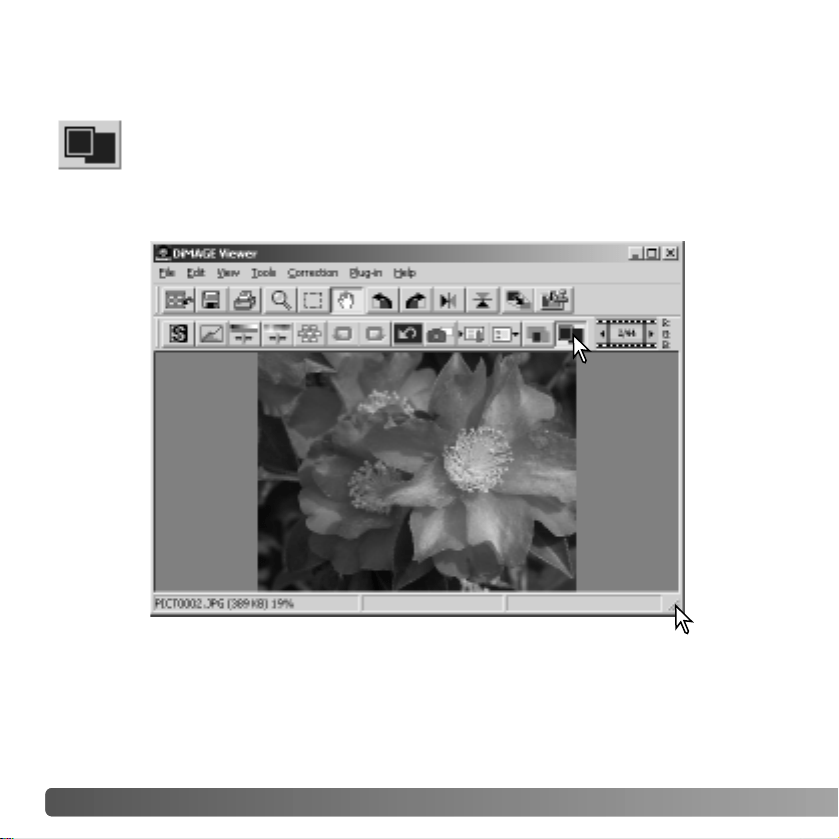
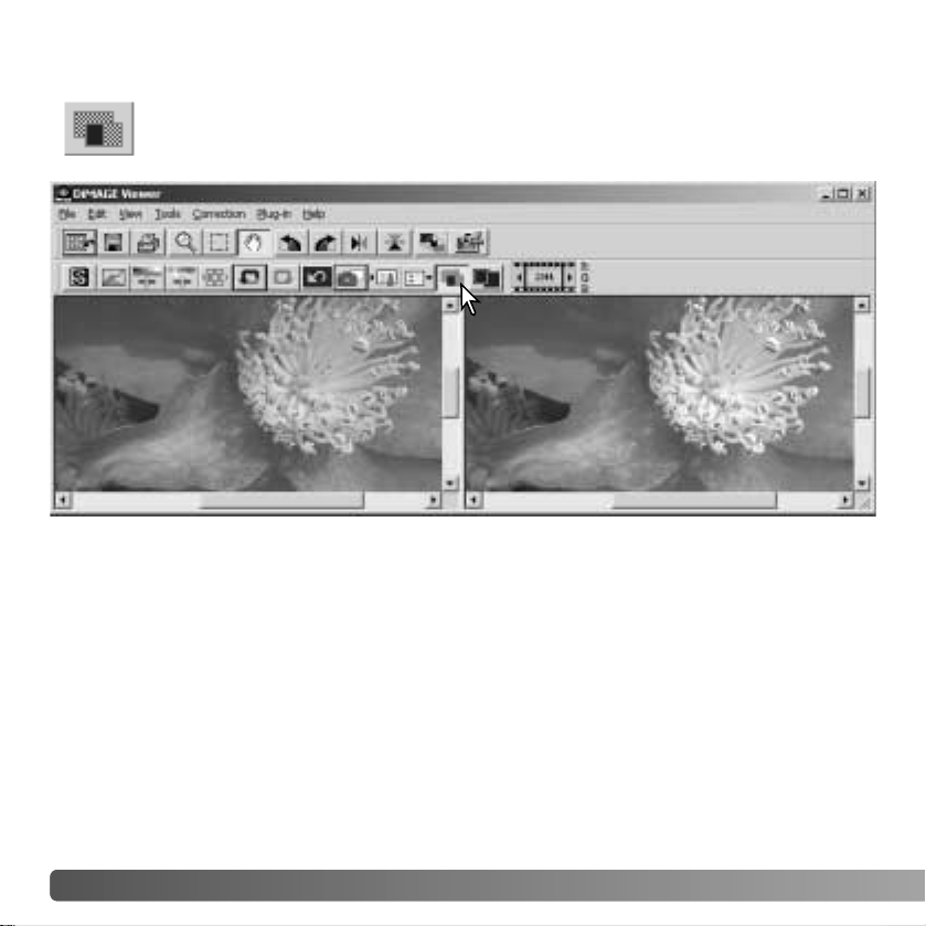
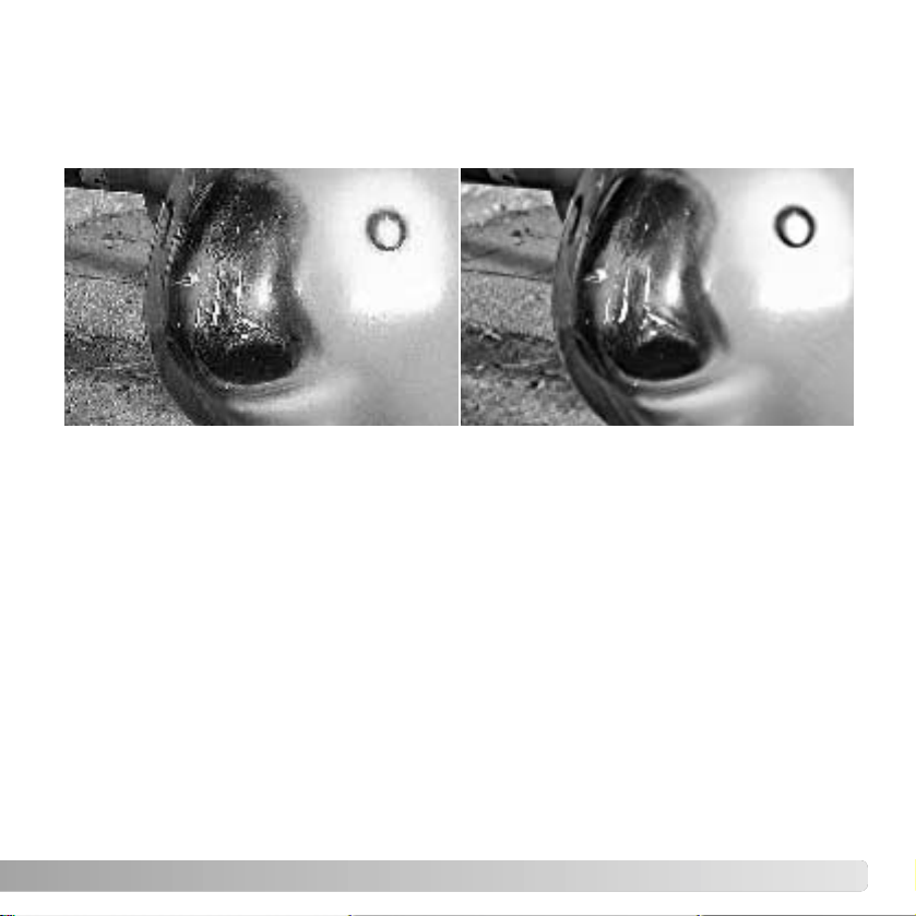
COMPARING PRE AND POST CORRECTION IMAGES
Clicking the comparison display button divides the image display area in two.
The original image is on the left and the corrected image is on the right. To
display the corrected image only, click the comparison display button again.
Original image Corrected image
Changes made with the magnifying tool, grab tool, or scroll bars on one image will be
applied to the other. Using the fit-to-window button automatically resizes both images to
fit the display area.
37
Images of black text or line art on
white backgrounds can be
processed to sharpen detail and
reduce uneven illumination. Only
images with horizontal and vertical
dimensions between 240 pixels and
3072 pixels can be processed.
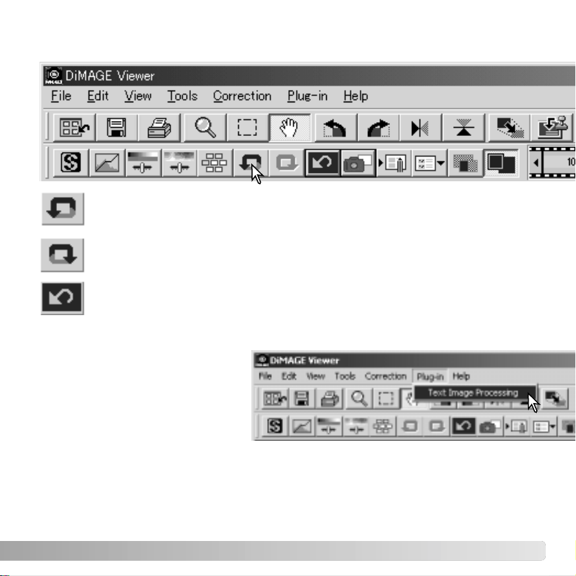
Simply display the image in the correction window and select the text-image-processing
option from the plug-in menu. To reset the correction, select the text-image-processing
option again from the plug-in menu.
Click the undo button to cancel the last image correction applied to the image.
Image corrections can continue to be undone as far as the computer memory
capacity allows.
Click the redo button to reapply the last image correction canceled with the undo
button.
Click the reset-all button to cancel all image corrections applied to the image.
UNDOING AND REDOING AN IMAGE CORRECTION
PROCESSING IMAGES TEXT AND LINE ART
38
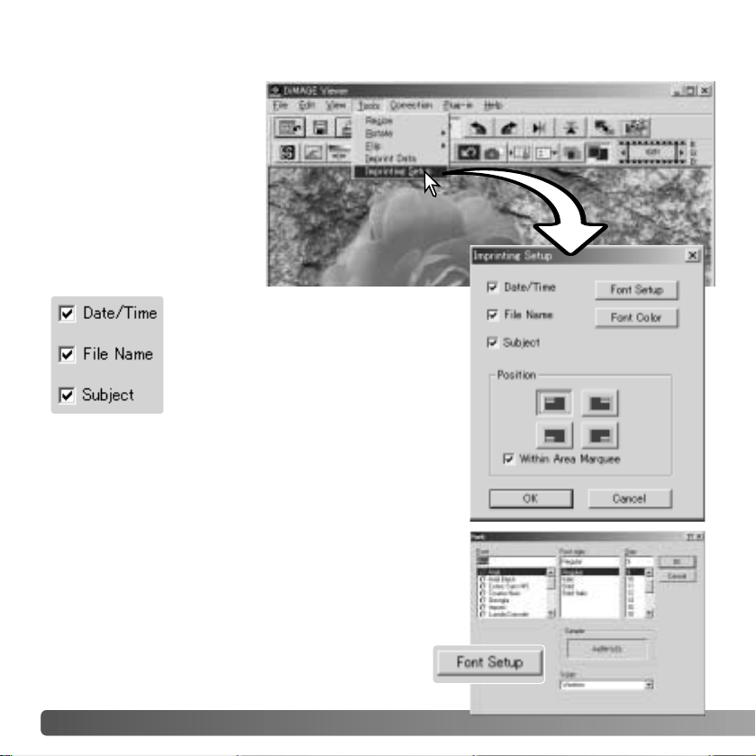
DATA IMPRINTING
The date and time of
recording, file name, and
the subject line can be
imprinted into the image.
To add a subject line to an
image, see page 25.
Select the imprinting-setup
option from the tool menu
to open the setup dialog
box.
Select the information to be imprinted
by checking the appropriate boxes.
Click the appropriate button to select the corner to
imprint the data. If the within-area-marquee check box
is selected, the data will appear inside the area
marquee in the position selected. For more about the
area marquee, see page 64.
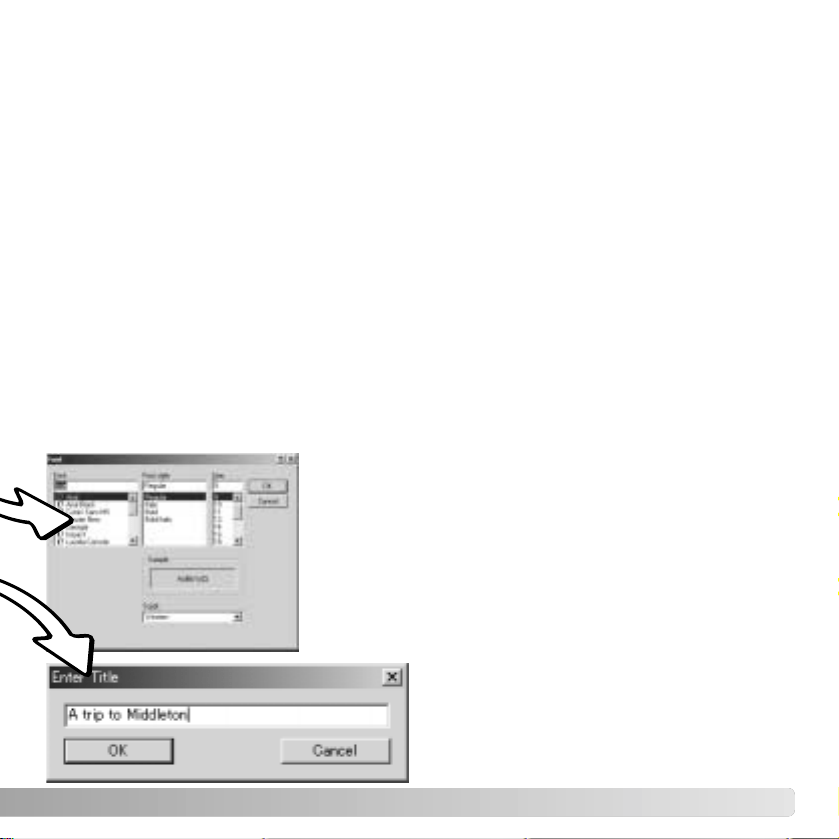
The font, font style, and point size can be
specified. Simply click the font-setup button to
open the font dialog box. The sample area will
reflect the settings. The script can be selected
from the drop-down menu at the bottom of the
window. The fonts and scripts available vary with
the computer system.
BASIC IMAGE PROCESSING
39
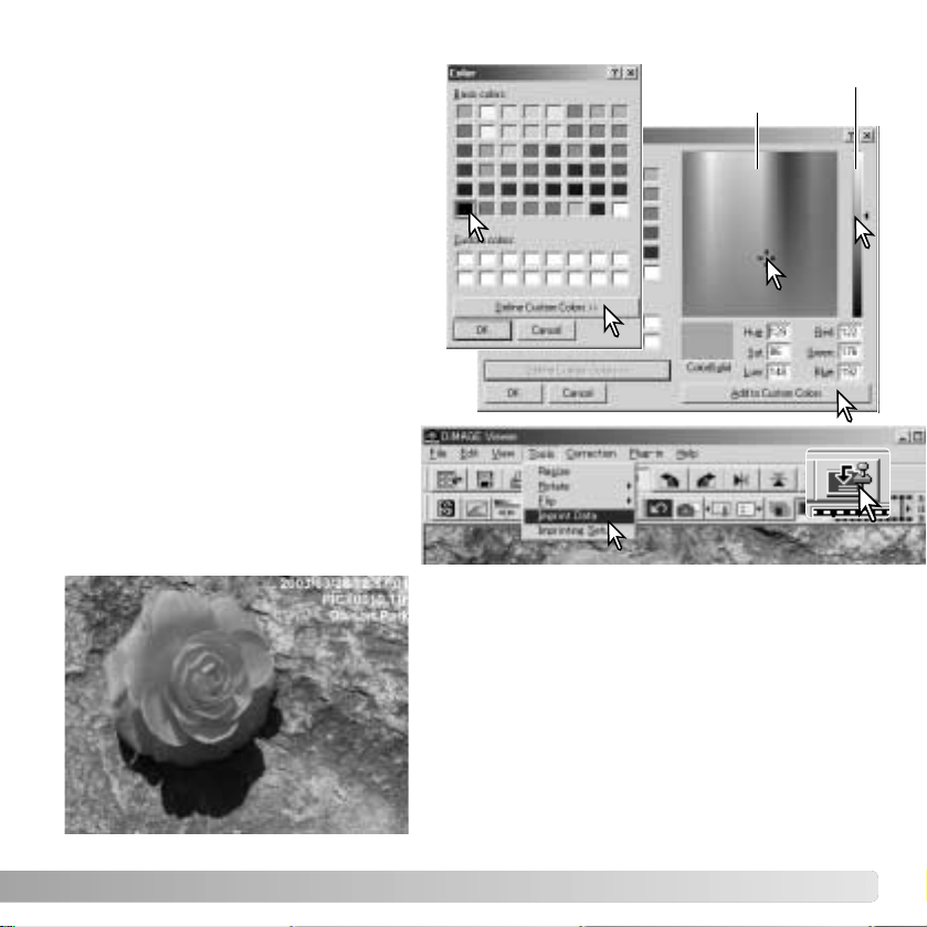
The font color can be specified. Click the
font-color button to open the color dialog
box. 48 colors are available. Click on the
color sample to select it.
Custom samples can be created; click
the define-custom-colors button to open
the palette. Values can be entered into
the text boxes or a color can be created
by clicking on the hue/saturation and
luminance fields. Click the add-to-
custom-colors button to add the color to
the custom palette. Click the custom
sample and then the OK button.
Luminance
Hue / Saturation
Click the OK button in the data-
imprinting dialog box to complete the
operation. Select the data-imprint
option from the tool menu or click the
data-imprinting button to apply the
settings.
The relative size of the imprinted data varies
with image size. To cancel the imprinting
function, select the data-imprint option from the
tool menu or click the data-imprinting button
again.
When the image is saved, the data will be
embedded into the image. Always rename the
file to protect the original image.

40 SAVING IMAGES
SAVING IMAGES
RESIZING AN IMAGE TO BE SAVED
Enter the new width or height value in the text
boxes. Only one value needs to be entered, the
other value will adjust automatically to keep the
image proportions unchanged. The dimensions
cannot exceed 5120 X 3840 pixels.
Select bilinear or bicubic interpolation.
Click the OK button to set the new dimensions.
The image is resized when it is saved or printed.
SAVING AN IMAGE
Click the save button on the tool bar or select the save option on the
file menu. The image will be saved in its original location overwriting
the current file. If a JPEG image is saved, the save-as dialog box will
open; the location and compression rate must be specified, see next
page.
To resize the displayed image, click the image-
size button. The image size window will open.
41
Click the save button
to save the image.
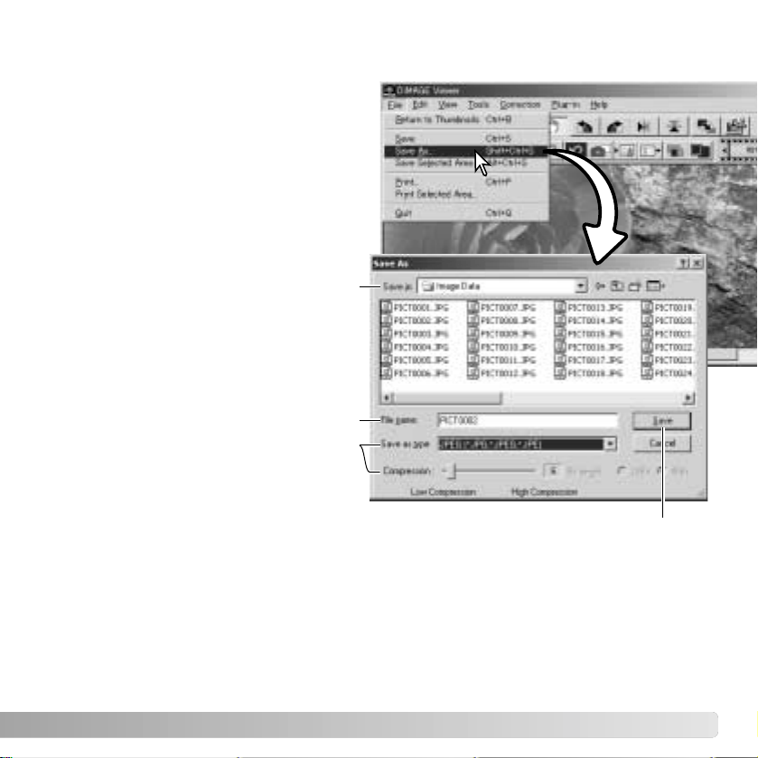
CHANGING THE IMAGE NAME OR FORMAT
To save an image file under a new name or
in a new file format, select the save-as
option from the file menu. The save-as
dialog box will open.
Specify the location to save the file.
Enter the file name without an extension.
Specify the file format of the image from
the drop-down menu. The file does not
need to be saved in the original file
format. If JPEG is selected, the
compression rate must be fixed using the
slide bar at the bottom of the dialog box.
The higher the compression rate, the
smaller the file size, and the lower the
image quality.

42 PRINTING
PRINTING
With the image to be printed displayed
in the correction window, click the print
button or select the print option from
the file menu to open the print setup
window.
43
Position
The image can be positioned within the printing area. Simply click on the appropriate
radio buttons. Changes are immediately displayed in the preview area.
Size
Clicking the top radio button allows manual adjustments based on printing resolution or
dimensions. Enter the print resolution or one of the dimensions in the text box and click
the apply button; the other two values and the preview display change accordingly. With
manual adjustments the print image can be made bleed to the edge of the printing area
by setting the dimensions larger than the area.
Click the size-to-page radio button to automatically size the image to the printing area.
The print size can be adjusted between 1% and 100% of the printing area in integers.
Click the apply button each time the percentage of reproduction is change to see the
result in the preview area.
Preview area
To preview the affect of the printing parameters. When the any of the size settings are
changed, the apply button must be used to view the change.
Printer setup
To access the setup dialog box of the printer.
Print
To print the image.
Close
To close the print window without printing the image.
44 PRINTING
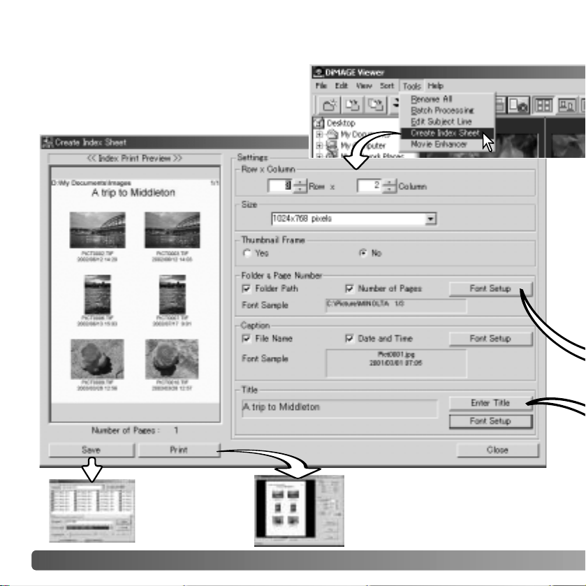
CREATING AN INDEX SHEET
Multiple images can be laid out in index
sheets. Select the images in the thumbnail
display choose the create-index-sheet option
from the tool menu.
Click the save
button to save
the index sheet
as a file.
Click the print button to open the
print-preview dialog box. See
page 42 for information on print
settings.
45
The font, font style, and point size can be specified for the
folder path and page number, caption, and title. Simply
click the font-setup button to open the font dialog box.
The sample area will reflect the settings. The script can
be selected from the drop-down menu at the bottom of
the window. The fonts and scripts available vary with the
computer system.
Select from the following setting to lay out the index sheets. All changes are reflected in
the preview display.
Rows x Column - to lay out the images in a specified number of horizontal rows and
vertical columns.
Size - to select the pixel dimensions of the index sheet. The greater the number of pixels,
the fine the image resolution and the larger the file size.
Thumbnail frame - to print a black frame around each image. The frame can indicate
the extent of an image that has a large area of white near the edges such as a cloudy
sky.
Folder & Page Number - to print the folder name and location of the images and the
page number and total number of pages of the index sheets.
Caption - to print the file name, and date and time of recording under each image.
Title - to print a title at the top of each sheet.
Enter the title of the index sheets in the
dialog box. Click the OK button; the title will
appear in the title field as well as at the top
of the preview display.
46 ADVANCED IMAGE PROCESSING
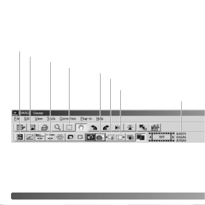
ADVANCED IMAGE PROCESSING
RGB value display
Load image-correction
Job button (p. 67)
Save image-correction
Job button (p. 66)
Snapshot button (p. 65)
Hue, saturation, and lightness button (p. 60)
This section covers the advanced image-processing tools in the DiMAGE Viewer.
Adjustments to color, contrast, brightness, hue, and saturation can be made. Functions to
view and save image corrections are also available. The basic image-processing section
on pages 26 through 39 should be read before continuing.
The RGB display will show the color values for any point on the image. The first number
are the values for the original image before corrections are applied followed by the
current values. Simply place the mouse pointer on the image area to see the RGB values
of that point. Pressing the shift key (Windows) or command key (Macintosh) will display
the CMY values.
Sharpness button (p. 62)
Area-marquee (p. 64)
Tone curve/histogram button (p. 47)
47
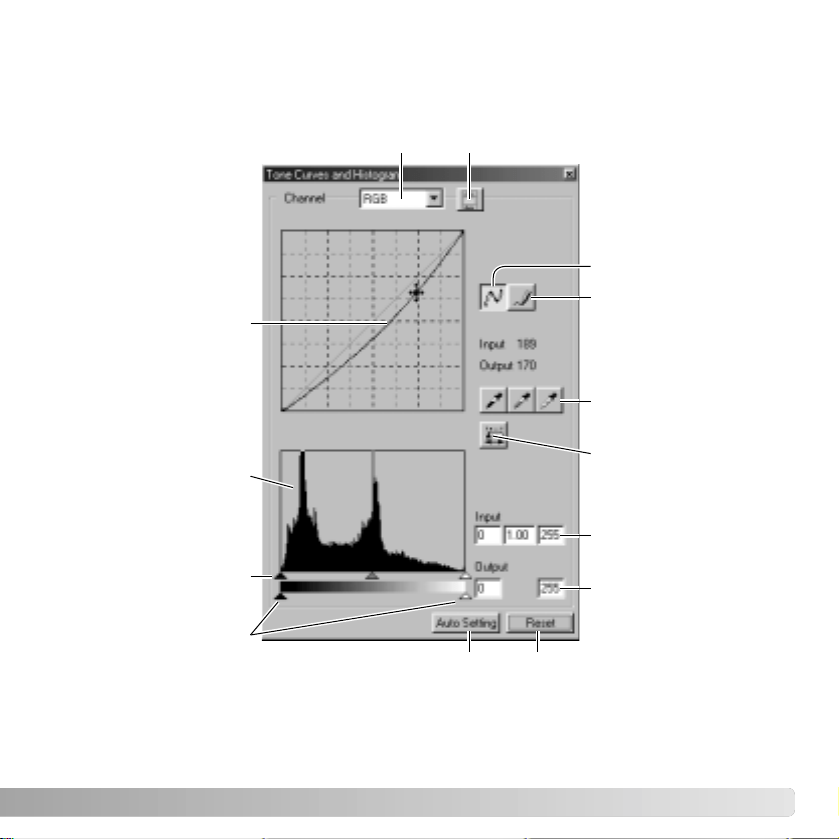
Click the tone-curve/histogram button to display the palette.
THE TONE
-CURVE / HISTOGRAM PALETTE
Reset buttonAuto-setting button
Output shadow and
highlight text boxes
Output shadow and
highlight sliders
Input shadow, gamma,
and highlight sliders
Input shadow, gamma,
and highlight text
boxes
Histogram
Apply button
White, gray, and black-
point buttons
Tone curve
Smooth curve button
Freehand curve button
Channel list box Color-histogram button
Place the mouse pointer over the tone curve. Click
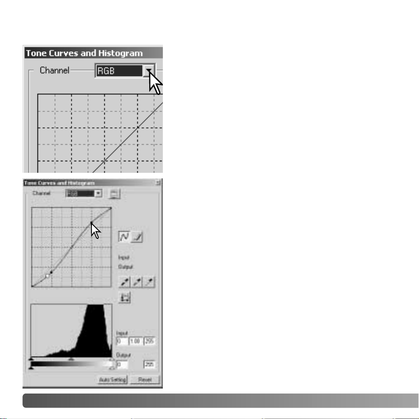
and drag the curve.
Each time the tone curve is clicked, a new node will be
attached to the curve. The nodes can be moved by
clicking and dragging. The input and output levels of
the node are displayed as it is moved. The input level
(horizontal axis) refers to the original image, and the
output level (vertical axis) refers to the correction
applied to the image.
Any corrections made on the tone curve are
immediately applied to the displayed image. By
placing the mouse pointer on the displayed image, the
grey or color level of that point will be indicated on the
tone curve by a white circle.
The reset button cancels all corrections in all
channels.
48 ADVANCED IMAGE PROCESSING
Click the arrow next to the channel box to select the
channel from the drop-down menu. To make
adjustments to the color balance of the image, select
the appropriate color channel. To adjust the contrast or
brightness of the image without affecting the color,
select the RGB channel.
The tone curves can be displayed with keyboard
shortcuts. While holding the control key (Windows) or
command key (Macintosh), press “1” to display the red
channel, “2” to display the green channel, “3” to
display the blue channel, or “0” (zero) to display the
RGB channel.
USING THE TONE CURVE
49
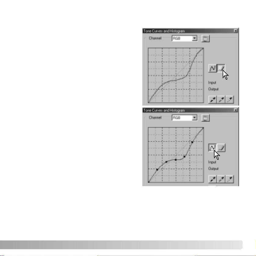
DRAWING TONE CURVES BY FREEHAND
Click the freehand-curve button (1). The mouse
pointer changes to the pencil tool when placed
in the tone-curve box.
Click and drag the pointer to draw a new curve.
Extreme image manipulations are possible with
the freehand curve tool.
To smooth a rough freehand curve, click the
smooth-curve button (2). Nodes will be
automatically placed on the curve and can be
adjusted with the mouse.
With extreme freehand curves, the smooth
curve button may significantly change the
shape of the curve. Click the undo button to
return to the original freehand curve.
1
2
50 ADVANCED IMAGE PROCESSING
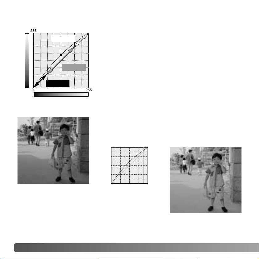
The tone curve is a graphic representation of the
brightness and color levels of the image. The bottom axis
is the 256 levels of the original image (input data) from
black to white. The vertical axis is the corrected image
(output data) with the same scale from top to bottom.
The bottom left portion of the graph represents the dark
colors and shadow areas of the image. The middle section
represents the mid-tones: skin, grass, blue sky. The top
right section is the highlights: clouds, lights. Changing the
tone curve can affect the brightness, contrast, and color of
the image.
A SHORT GUIDE TO TONE
-CURVE CORRECTIONS
Input
Output
Highlights
Mid-tones
Shadows
Bring out detail in the shadows
With the RGB channel selected, place the smooth-curve
cursor on the center of the curve. Click and drag the curve
up. Look at the displayed image to judge the result. The
adjustment can be very small and still have a significant
impact on the image. Moving the tone curve down will
make the image darker.
This is a simple technique to make a subject hidden in the
shadows brighter. Unlike the brightness level control (page
33), this method of correction will not loose details in the
highlight areas of the image.
By selecting individual color channels on the tone curve, adjustments to the overall color
of an image can be made. This can be used to eliminate unnatural color casts or add
warmth to a picture.
If the image is too red, green, or blue, simply drag the
corresponding color-channel curve down until the
color appears natural. If the color cast is
predominantly one of the secondary colors, cyan,
magenta, or yellow, move the curve of the
complementary color up. For example, if the image is
too yellow, move the blue curve up, see the color
example on page 2. For more on color, see page 35.
51
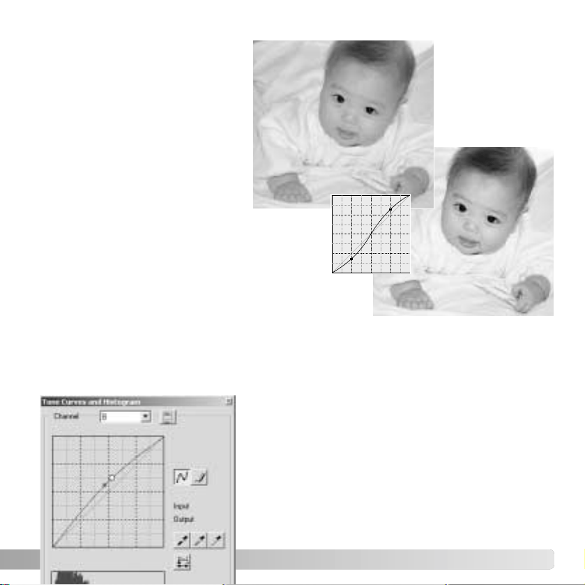
The contrast of an image can be
changed. The light blue 45° line on
the tone-curve graph represents
the original contrast of the image.
Making the angle of the tone curve
greater than 45° will increase the
contrast of the image. Making the
angle less than 45° will reduce the
contrast.
Increasing contrast
With the RGB channel selected, click on the tone
curve near the top and bottom to add two nodes.
Slightly move the top node up and the bottom
node down. This will increase the angle of the
central portion of the tone curve and increase the
contrast of the image without making an overall
change in image brightness.
Correcting color

52 ADVANCED IMAGE PROCESSING
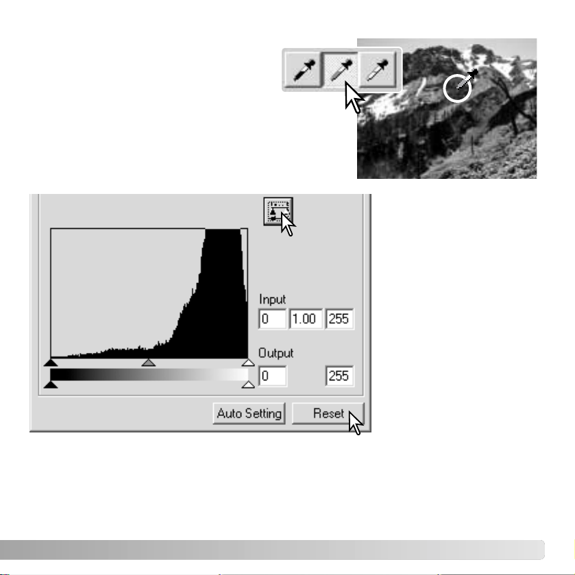
On the tone-curve / histogram palette, corrections
can be made by specifying a white, black, and gray
point within the image. Locating an appropriate
neutral area within the image is critical to correctly
calibrate the software. When the dropper tool is
selected, the RGB display is active and can be used
to evaluate the image area. All changes are
immediately reflected in the displayed image.
WHITE, BLACK
, AND GRAY-POINT CORRECTIONS
Click the white-point button; the mouse
pointer changes to the white dropper
tool.
Click the black-point button.
With the dropper tool, click on the brightest neutral
area of the image to define it as the white point. The
values of the image will be adjusted based on the
selected point. The default level for the white point is
255 for each RGB channel.
With the dropper tool, click on the darkest neutral area
of the image to define it as the black point. The values
of the image will be adjusted based on the selected
point. The default level for the black point is 0 for each
RGB channel.
53
Click and hold the apply
button to show the change
on the histogram.
Click the reset button to
cancel all corrections.
Click the gray-point button. The grey
point controls the color of the image.
With the dropper tool, click a neutral area of the image
to be defined as the gray point. The area used to
calibrate the gray point must be neutral. The
brightness level of the area is not important, but if the
area has a definite color, the image will not be color
balanced correctly.
54 ADVANCED IMAGE PROCESSING
The white and black-point values are set to 255 and 0 for each RGB level. Changing
these values allow the calibration of an image with no true white or black. This is an
advanced image-processing tool.
SETTING THE WHITE AND BLACK
-POINT VALUES
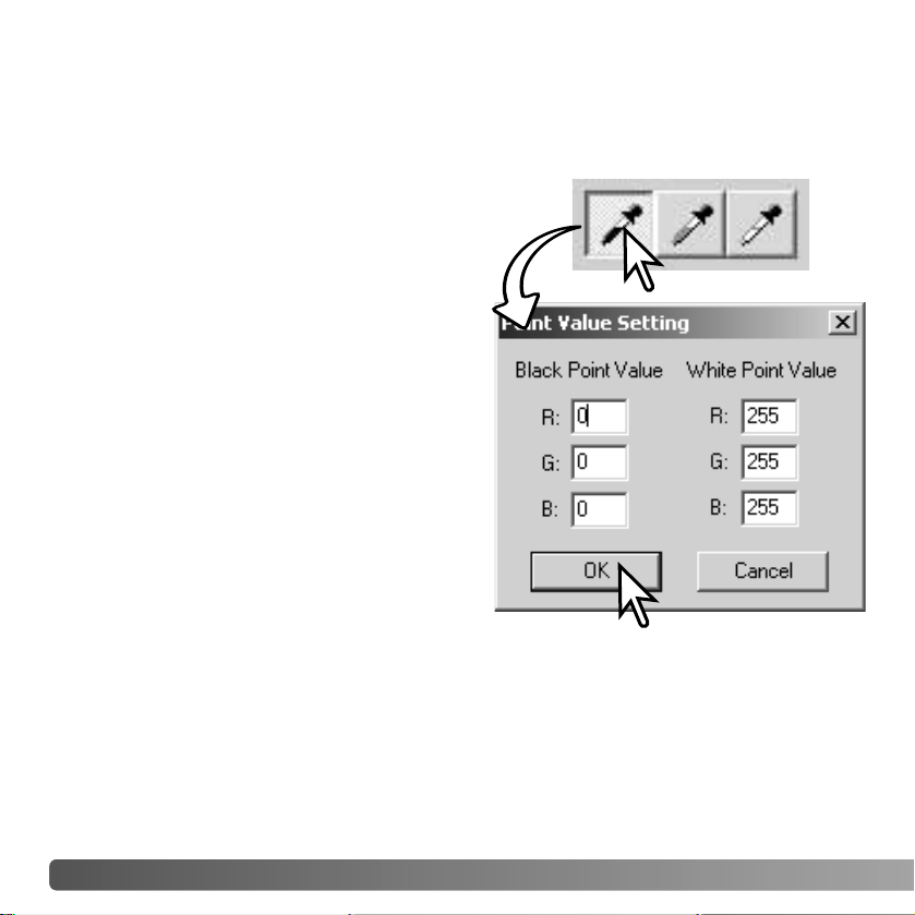
Double-click on either the white-point or black-
point button to activate the point-value-setting
dialog box.
Input the new white-point or black-point values.
Click [OK].
With the point-value-setting dialog box open,
the mouse pointer can be used to measure the
color of any point on the displayed image.
Press the shift key (Windows) or command key
(Macintosh) to display the CMY levels in the
RGB display. The RGB display shows the
original values for the image on the left and the
current values for the image on the right.
Calibrate the image following the steps in
white, black, and gray point corrections
section.
55
TONE-CURVE
/ HISTOGRAM AUTO SETTING
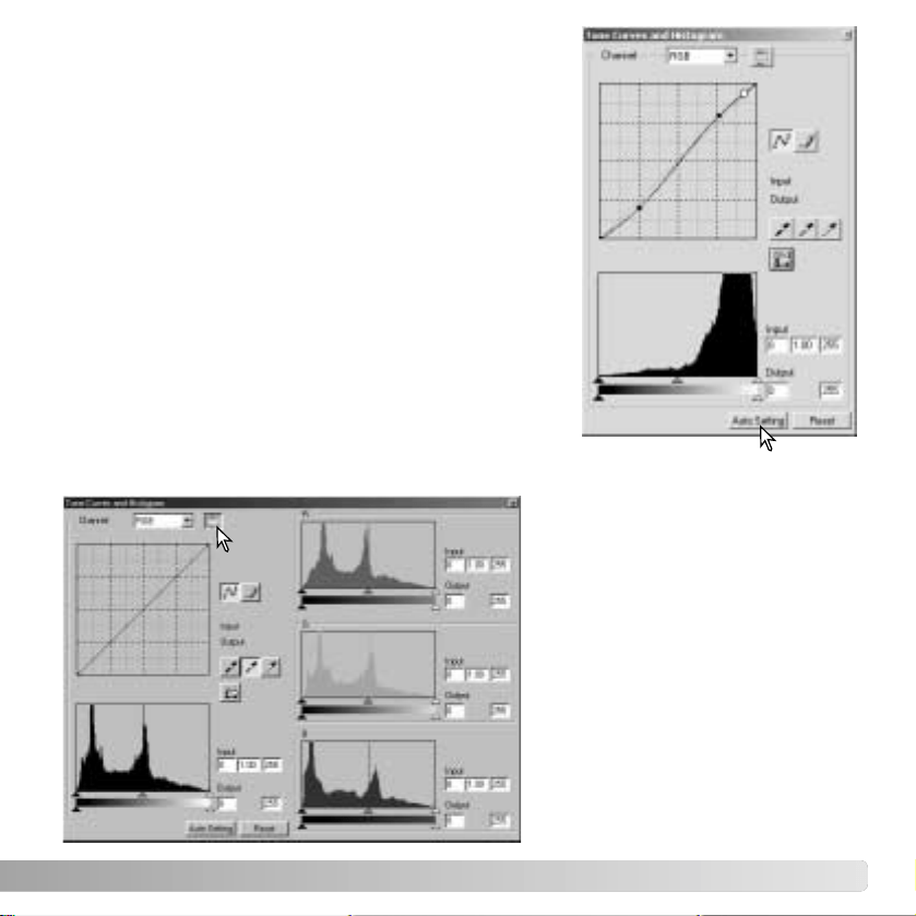
Click the auto-setting button. The change is immediately
reflected in the displayed image.
The auto-setting function automatically adjusts the tone
curve and histogram to maximize image data. The
darkest pixels in the image are set to a black level for 0,
the brightest pixels are set to a white level of 255, and
the rest of the pixels are distributed between them
equally. To view the change in the histogram, press the
apply button. Click the reset button to cancel the auto
setting.
DISPLAYING THE COLOR HISTOGRAMS
Click the color-histogram button to
view the red, green, and blue
histograms.
Click the histogram RGB display
button again to close the color
histogram display.
56 ADVANCED IMAGE PROCESSING
The color histograms can be displayed with the channel list box or with keyboard
shortcuts. While holding the shift key (Windows) or command key (Macintosh), press “1”
to display the red channel, “2” to display the green channel, “3” to display the blue
channel, or “0” (zero) to display the RGB channel.
HISTOGRAM CORRECTIONS
The histogram indicates the distribution of pixels with specific brightness and color values
of the displayed image. Using the histogram can maximize the output of the image data.
Changes made with the histogram are also displayed on the tone curve.
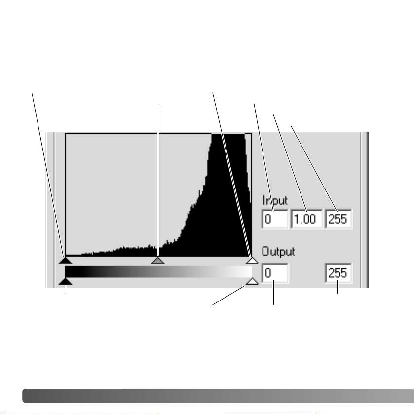
Input shadow slider
Input gamma slider
Input highlight slider
Input shadow text box
Input gamma text box
Input highlight text box
Output shadow slider
Output highlight slider Output shadow text box
Output highlight text box

57
The highlight level, shadow level, and gamma can be set manually. The histogram can
be used to maximize the distribution of the pixels in the image. All the levels on the
histogram are displayed numerically to the right of the sliders. These numbers can be
changed with the keyboard.
The gamma slider defines the mid-tones of the image. Dragging the gamma slider to the
right will darken the image, and dragging it to the left will brighten it. Similar to the tone-
curve correction described on page 50, the gamma slider allows the brightness of the
image to be adjusted without loosing image information.
The input highlight slider sets the white level. As the slider is moved to the left, an
apparent increase in contrast can be seen in the displayed image. All pixels to the right
of the slider are set to 255 and any image detail they may contain will be lost. This can
be an important tool for improving copy images of text on a white background. Uneven
illumination, or faded or stained paper can be distracting when copying text or line art. By
adjusting the white level, the imperfections of the white background can be eliminated
leaving only the darker text visible.
The input shadow slider sets the black level. As the slider is moved to the right, an
apparent increase in contrast can be seen in the displayed image. All pixels to the left of
the slider are set to 0 and any image detail they may contain will be lost.
The black and white output levels can be adjusted. By moving the output highlight and
shadow sliders, the contrast of the image can be reduced.
For examples of histogram corrections, see the following section.
58 ADVANCED IMAGE PROCESSING
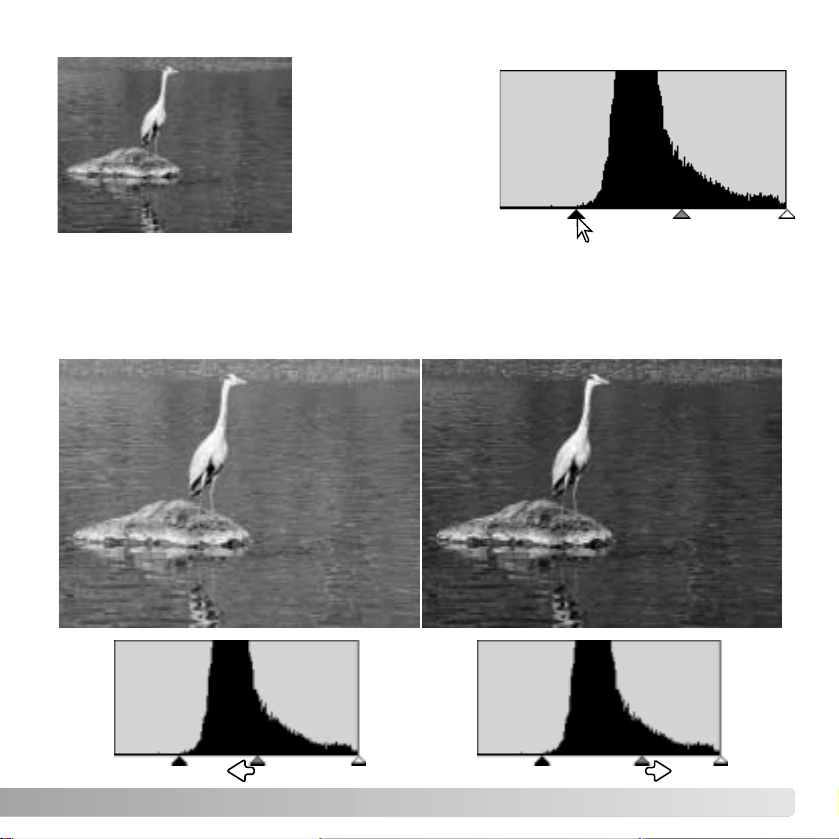
A SHORT GUIDE TO HISTOGRAM CORRECTIONS
This guide shows simple corrections that can be made with a histogram. Unlike the tone
curve, the histogram provides information on a specific image. This can used to evaluate
the image and make adjustments accordingly.
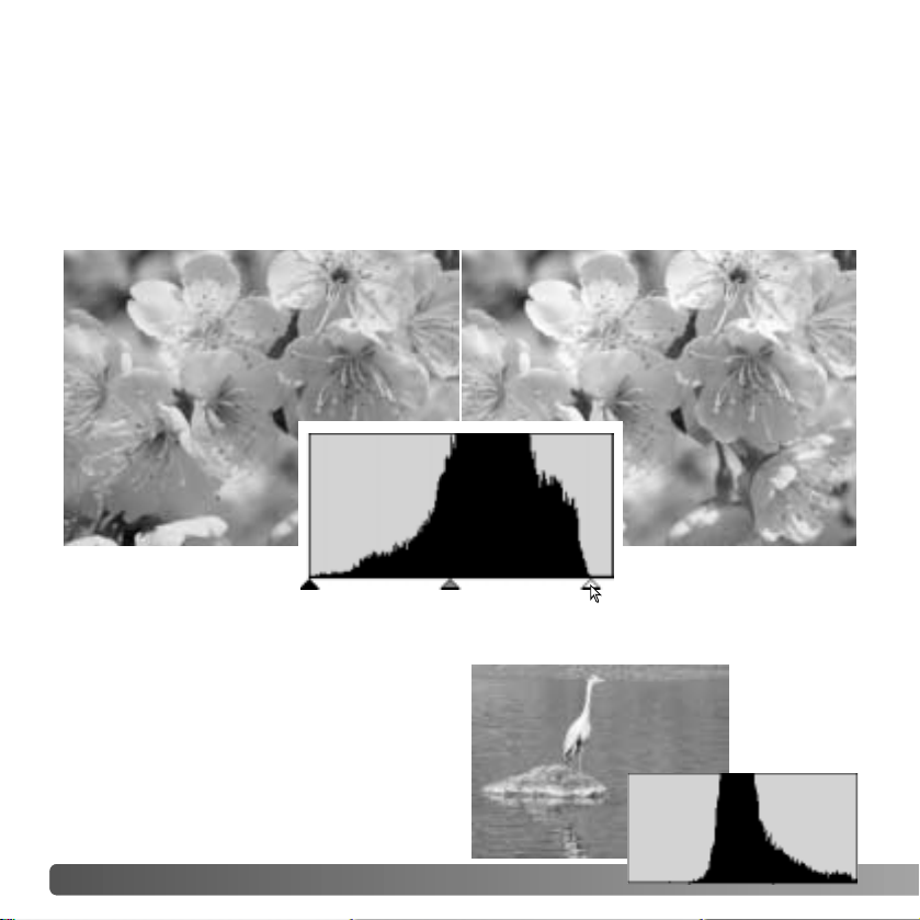
The histogram of the cherry blossoms shows a gap at the right and the flowers look a
little grey. This is caused by slight underexposure when the image was captured.
By moving the highlight slider to the left to set the white point to where the pixel
distribution ends, the whites become more brilliant and the contrast increases.
This image is flat. The pixel distribution in
the histogram reflects the low-contrast
scene. The lack of any strong shadows or
dark tones is indicated by the absence of
pixels on the left of the histogram. Most of
the detail is concentrated in a narrow range
in the mid-tones.
59
By moving the
shadow slider to the
right to set the black
level to where the
pixel distribution
begins, image
contrast is improved.
The gamma slider can be used to change the relative distribution of the tones in the
image. By moving the gamma slider to the left toward the shadows, the image becomes
lighter. By moving the gamma slider in the opposite direction, the image becomes darker.
However, unlike the brightness control in the brightness, contrast, and color-balance
palette (p. 33), details are not lost in the shadows or highlights.
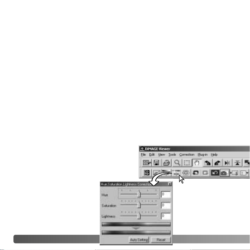
60
HUE, SATURATION
, AND LIGHTNESS PALETTE
This palette adjusts the image in reference to the HSB color model. These controls can
be used to manipulate the color image rather than producing a realistic representation.
The HSB color model defines color based upon human perception rather than
photographic processes. Hue refers to each separate color in the model. Saturation is
how vivid each colors is. Lightness describes how bright or dark a color is in the color
space.
The hue control is not a color balancing tool. It is a creative tool. When changing hue in
the palette, each color is assigned a new hue depending on the degree of rotation
through the color space. For example, a very simple color space could have three colors:
red, green, and blue. I have a red barn next to a green tree with a blue sky. Now I rotate
the my image in the color space; the colors are reassigned a new hue based on the
position - the barn is green, the tree is blue, and the sky is red. The HSB color space is
similar, but with many more hues; see the color example on page 91.
Unlike the brightness control in the brightness, contrast, color balance palette, the
lightness control does not change the apparent density of the colors equally. For
example, with an extreme increase in lightness, blue will not appear as light as yellow.
Click the hue, saturation, and lightness button to
open the palette.
ADVANCED IMAGE PROCESSING
61
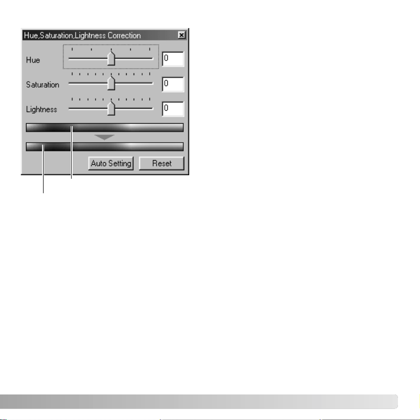
Drag the hue, saturation, or lightness slider, or
enter specific values in the corresponding text
box to make corrections.
Dragging each slider to the right or inputting a
positive number in the text box increases the
saturation, and lightness. The hue slider rotates
the colors in the image through the color space;
the maximum position to the right (180°) is the
same as the maximum position to the left
(–180°).
Two color spaces are displayed at the bottom of
the palette. The top bar indicates the color
space of the original image. The bottom bar
displays the relative changes to the color
space.
Changes will be reflected in the displayed
image. Click the reset button to cancel any
changes.
Clicking the auto-setting button adjusts the saturation automatically without affecting the
hue or lightness. Click the reset button to cancel any changes.
Auto-setting button
Original color space
New color space
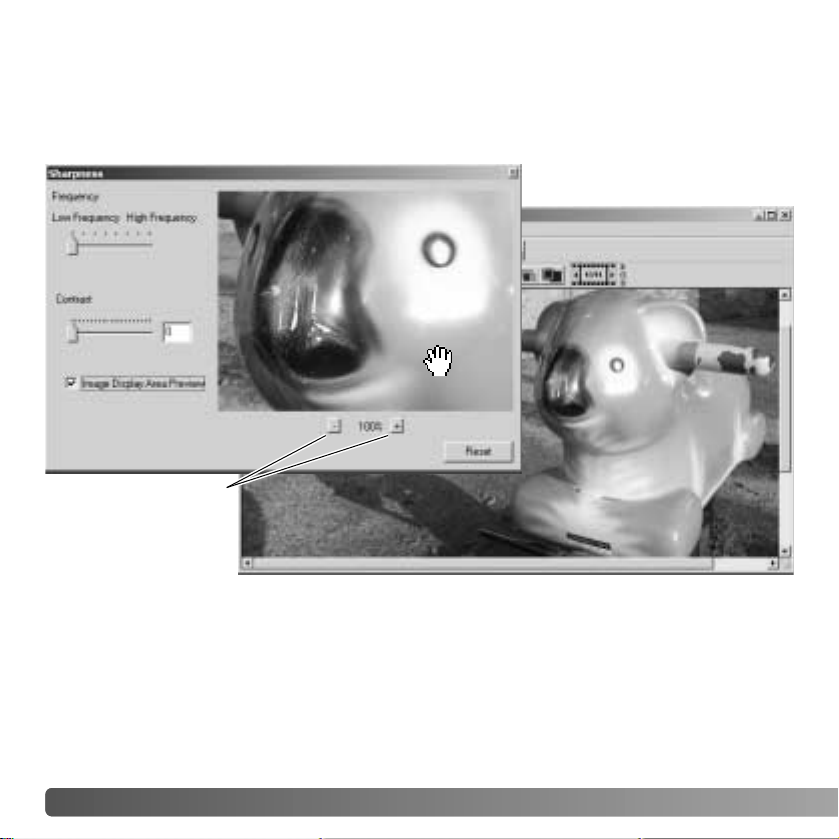
62 ADVANCED IMAGE PROCESSING
The apparent sharpness of the image can be increased. Sharpness is a very subtle, but
can have a powerful affect on overall image quality. Click the sharpness button or select
Sharpness from the image-correction option in the correction menu to open the palette.
SHARPNESS
Reduce and
enlarge buttons
The preview image can be scrolled using the mouse. Place the mouse pointer over the
image area; it will change to the grab tool. Click and drag the image to scroll. Click the
display-area-preview check box to view the effects of the sharpness controls on the
image displayed in the main window.
63
Frequency slider - affects the sharpness of image details. The high frequency setting
maximizes resolution, and the low-frequency setting maximizes acutance. The optimal
frequency setting will vary from image to image. It is recommended to view the image at
various magnifications to judge the results.
Contrast slider - controls the contrast of the set frequency. The degree of sharpness can
be set between 0 and 2 in 0.1 increments. The higher the value, the greater the contrast;
compare the examples above, which are at the maximum setting, with the original image
on the facing page. The degree of sharpness can also be entered in the text box next to
the slider. Like frequency, the optimal contrast setting will vary from image to image.
Reduce and enlarge button - to adjust the size of the preview image in the sharpness
window. The preview image can be displayed at 25%, 50%, 100%, and 200%.
Reset button - resets all changes made to the image.
High-frequency setting Low-frequency setting
64 ADVANCED IMAGE PROCESSING
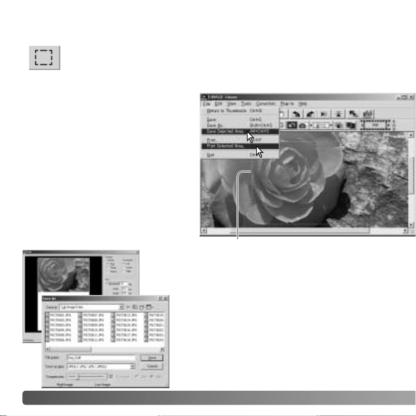
AREA MARQUEE -
SAVING OR PRINTING A PORTION OF AN IMAGE
Click and drag over the area of the
image to be selected. The area-marquee
tool will create a rectangle with a dashed
boarder.
The marquee can be moved by placing
the cursor within the area and clicking
and dragging. It can be resized by
clicking and dragging on the boarders.
Select the save-selected-area option or
the print-selected-area option from the
view menu.
Area marquee
When the print-selected-area option is chosen, the
print dialog box open. The selected area will be seen
in the preview display. See page 42 on how to make
print settings.
When the save-selected-area option is chosen, the
save-as dialog box will open. Enter the file name for
the selected area, choose the file format, specify the
location to which to save the file, and save the image
(p. 40).
An area of an image can be selected and saved as a separate image file or
printed. The marquee can also be used to specify the area used for data
imprinting (p. 38). Click on the area-marquee button on the tool bar or select the
area marquee from the cursor option of the view menu.
65
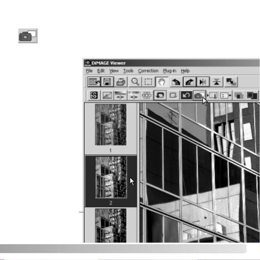
TRACKING IMAGE CORRECTIONS
- SNAPSHOT BUTTON
Image corrections can be stored temporarily as a thumbnail next to the
displayed image. Simply click the snapshot button on the tool bar or select the
snapshot option from the correction menu to create a thumbnail with the current
image corrections.
To return to a previous
image correction, click
on the corresponding
thumbnail. The
thumbnail image will
replace the displayed
image. The number of
snapshots that can be
made is only limited by
the computer memory.
To delete a snapshot,
click on the thumbnail
and press the keyboard
delete key.
Snapshot display area
66 ADVANCED IMAGE PROCESSING
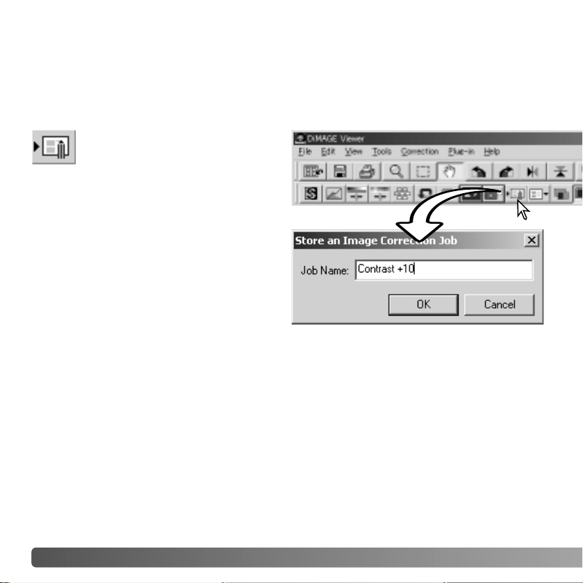
All corrections applied to an image can be saved as an image-correction Job. The Job
can be loaded into the utility at any time and applied to different images. This is a time-
saving function when a large number of images need too be processed with the same
correction settings.
Click the save image-correction Job
button or select the save-image-
correction-Job option from the
correction menu to save the current
image-correction settings.
Enter the Job name. Click the OK button to
save the settings.
SAVING IMAGE CORRECTIONS

67
LOADING IMAGE-
CORRECTION JOBS
Display the image to be corrected in
the image-correction window. Click
the load image-correction Job
button or select the load-image-correction-
Job option from the correction menu to load
a saved image-correction setting.
Click on an image-correction Job thumbnail to
select it. Click the OK button to apply the Job to the
displayed image.
Jobs are loaded into the snapshot display area.
Multiple Jobs can be loaded.

68 ADVANCED IMAGE PROCESSING
Certain digital cameras, such as the DiMAGE 7Hi, or DiMAGE A1, use a special file
format called Minolta-RAW. This file can only be read and processed by the DiMAGE
Viewer software. To open a RAW file, simply double click on it in the thumbnail display
The open dialog box is used to define the parameters for the image. First the color mode
of the image should be selected; if black and white is chosen, the white-balance and filter
controls are not available.
White balance controls the overall
color of the image. The drop-down
menu automatically applies the
camera setting used when the
image was captured or balances it
to a specific light source. The
preset white-balance settings vary
between camera model.
Click on the manual-setting check
box for fine control over white
balance. The grey-point dropper
tool can be used to balance the
image in reference to a neutral
point within the image area. The
color-temperature and CC index
slider and text box can be used to
enter the color temperature of the
scene when the image was
recorded.
Before adjusting white balance,
set the filter and saturation sliders
to zero (0) so that image color can
be judged accurately.
PROCESSING RAW IMAGES
b
c
a

69
Click on the gray-point button (a) to calibrate the white balance to a point within the
image; the cursor will change to the gray-point dropper tool. When the dropper is placed
in the image area, the RGB values of that point are displayed at the top of the window
(b). Click on a neutral point within the image to make the calibration (c). The point chosen
can be at any brightness level, but it must have no definite color. Although the filter and
saturation setting in the dialog box will not affect the calibration, the sliders should be set
to zero so that the results can be judged.
A Minolta color meter can be used to measure the approximate color temperature of a
scene when the RAW image is captured. The recorded color temperature and CC index
value from the meter can be entered in the text boxes to set the white balance. A green
CC value should be entered as a negative integer and a magenta value as a positive
integer. When making the reading, both the the color temperature and the CC value must
be recorded. See page 90 for information on color measurement.
If the camera’s filter, saturation, contrast, or sharpness controls were used when the
picture was taken, the settings will be displayed in the dialog box. Changes to these
settings are reflected in the preview image. The cursor can be used to measure the RGB
values of any point within the image. When a Vivid color image is opened, the saturation
level will be set to zero (0), but the high saturation level of the color mode will be applied
to the image. If color matching is on (p. 82), except when using the original color space,
any changes to the contrast will not be applied when the file is opened.
The image brightness can be adjust by ±2.0Ev with the exposure-compensation slider.
The slider will not reflect the degree of exposure compensation used when the image
was captured. Like the brightness control in the brightness, contrast, and color-balance
palette, detail can be lost in the highlights and shadows. To preserve these details, it is
recommended to open the image without compensating the exposure and adjust the
image brightness with the tone-curve / histogram palette (p. 47).
The reset button returns all setting to their initial position. The close button cancels any
settings made and closes the window without processing the RAW image. To apply the
settings to the image data and open the file, click the OK button.
70 ADVANCED IMAGE PROCESSING
Click the save button on the tool bar or select the save option from the file menu to save
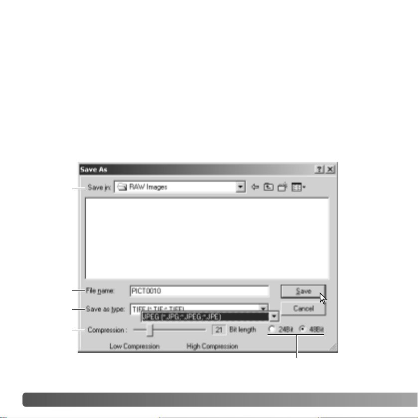
the displayed image. In the save-as window, specify the location to save the file (1). Enter
the file name without an extension (2).
Specify the file type of the image (3). If saved as a TIFF file, the bit length must be
selected (4): 24 bit or 48 bit. Once saved as 24 bit, the image cannot be saved as a 48-
bit file. If the data imprinting function is used (p. 38), the file can only be saved as 24 bit.
If saved as a JPEG file, the compression rate should also be set (5). The higher the
compression rate the smaller the file size and the lower the image quality.
Click the save button to complete the operation.
1
2
3
5
4
SAVING RAW IMAGES
71
SAVING RAW JOBS
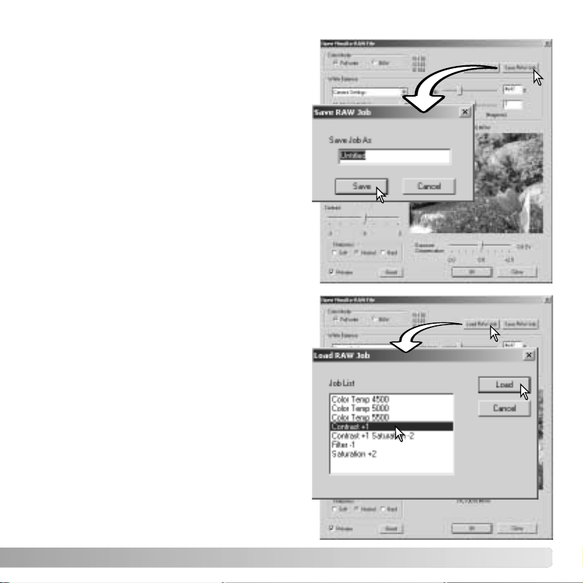
RAW processing settings can be saved and
applied to other images.
After all setting have been made on the open-
Minolta-RAW-file dialog box, click the save-
RAW-Job button. Enter the name of the Job in
the save-RAW-Job window and click save.
LOADING RAW JOBS
To apply a RAW Job to another image, click on
the load-RAW-Job button in the open-Minolta-
RAW-file dialog box.
Select the Job in the load-RAW-Job window
and click the load button to apply the settings
to the image.
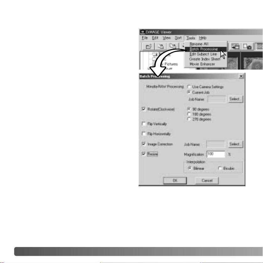
72 ADVANCED IMAGE PROCESSING
Except for RAW processing, the settings in
the dialog box are applied equally to all
images. If RAW images are included in the
batch, they can be processed with the
camera settings used when they were
recorded, or a RAW Job can be used (p. 71).
Click the select button to open the load-RAW
Job window and select the Job.
Images can be rotated or flipped.
To apply an image-correction Job click the
image-correction check box. The select
button opens the load-image-correction-Job
window (p. 67). Select the Job to be applied
to the images in the batch and click “OK.” If a
RAW Job and image-correction Job are
selected for batch processing, RAW images
will have both Jobs applied to them.
Images can be resized between 10% and 200%. If the result of the resizing exceeds the
maximum pixel size of 5120 X 3840, an alert message will be displayed. Reenter a new
magnification. When resizing images, select either bilinear or bicubic interpolation.
BATCH PROCESSING
Multiple images can be processed and saved
at one time. Highlight the images to be
processed on the thumbnail display and then
select the batch-processing option from the
tools menu. The batch-processing dialog box
will open.
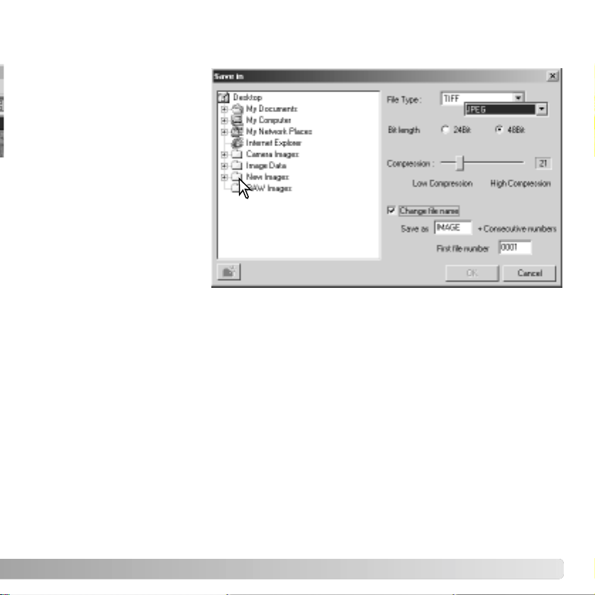
73
Click the OK button to begin processing. The save-in dialog box will open.
Select the location to save
the images on the folder
tree (1).
Specify the file type of the
images (2). If saved in the
TIFF format, the bit length
must be selected (3): 24 bit
or 48 bit. Once saved as 24
bit, images cannot be
resaved as a 48-bit file. If
saved in the JPEG format,
the compression rate
should also be set (4). The
higher the compression rate
the smaller the file size and
the lower the image quality.
Click the change-file-name check box (5) to rename the image files. Enter the file name
up to ten characters and enter the first serial number up to five digits.
Click the OK button to begin batch processing.
1
2
3
4
5
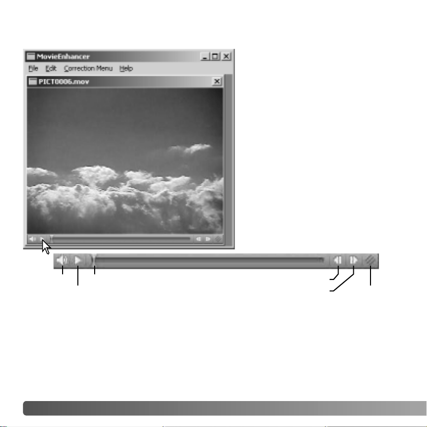
74 MOVIE ENHANCER
MOVIE ENHANCER
QuickTime must be installed on the
computer system for the Movie
Enhancer to be used. For QuickTime
system requirements, see page 7.
To open a movie file in this
application, simply double click on the
thumbnail in the DiMAGE Viewer
thumbnail display. To play the movie
clip back, use the controls at the
bottom of the screen. Only MOV or
AVI format images can be opened.
Volume
Play / Pause
Jog slider
Forward
Reverse
Resize
When the resize button is clicked and dragged, there is a maximum limit to how large the
screen area can be. The jog slider is used in editing (p. 76).
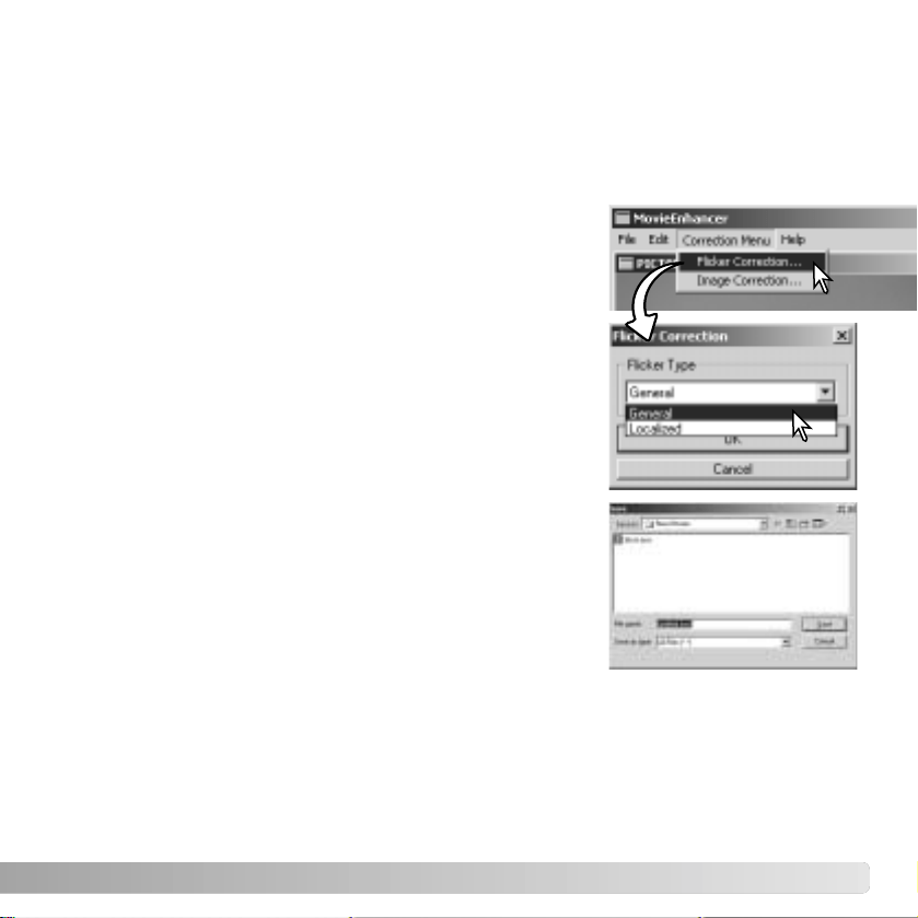
75
The Movie Enhancer can minimize flicker in 640 X 480 (VGA) or smaller movie files.
General flicker effects the overall image area evenly. Localized flicker is isolated to only
a portion of the image area; a scene with natural light and fluorescent lighting may only
show flicker in the area illuminated by the fluorescent lights.
FLICKER CORRECTION
The save dialog box will open; enter a new file name and
specify the location to save the file. The file can only be
saved in the MOV format.
Choose the type of flicker to be corrected on the drop-down
menu in the flicker-correction window. Click the OK button
to process the movie file.
With the movie displayed in the main window, select the
flicker-correction option from the correction menu.
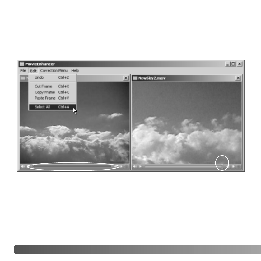
76 MOVIE ENHANCER
EDITING MOVIE FILES
The Movie Enhancer can join movie clips together, cut sections from a clip, or copy
sections from one clip to another with the edit menu. Open the necessary movie files in
the main window with the file menu.
Click on the first movie clip to select it; the slider bar should be dark (1). If not, choose
the select-all option from the edit menu to darken the bar and indicate the selection.
Select the copy-frame option from the edit menu.
Click on the second clip. Position the jog slider all the way to the left to attach the first clip
to the beginning of the second or all the way to the right to attach it to the end (2).
Select the paste-frame option from the edit menu to complete the operation.
1
2
Splicing two movie clips
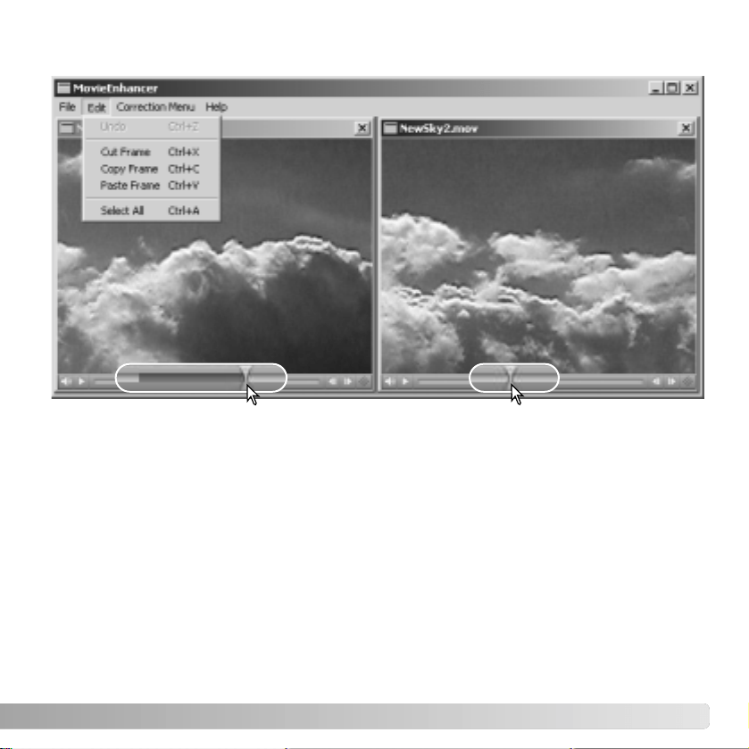
77
1
2
In the first movie file, use the jog slider to locate the beginning of the section to be pasted.
While pressing the shift key, drag the jog slider to mark the frames in the section (1); the
slider bar darkens to indicate the selected section. To deselect the section, click on a gray
area on the slider bar.
Select the copy-frame option from the edit menu.
On the second movie clip, use the jog slider to locate the point to paste the copied section
(2).
Select the paste-frame option from the menu to complete the operation.
Copying sections from one movie to another
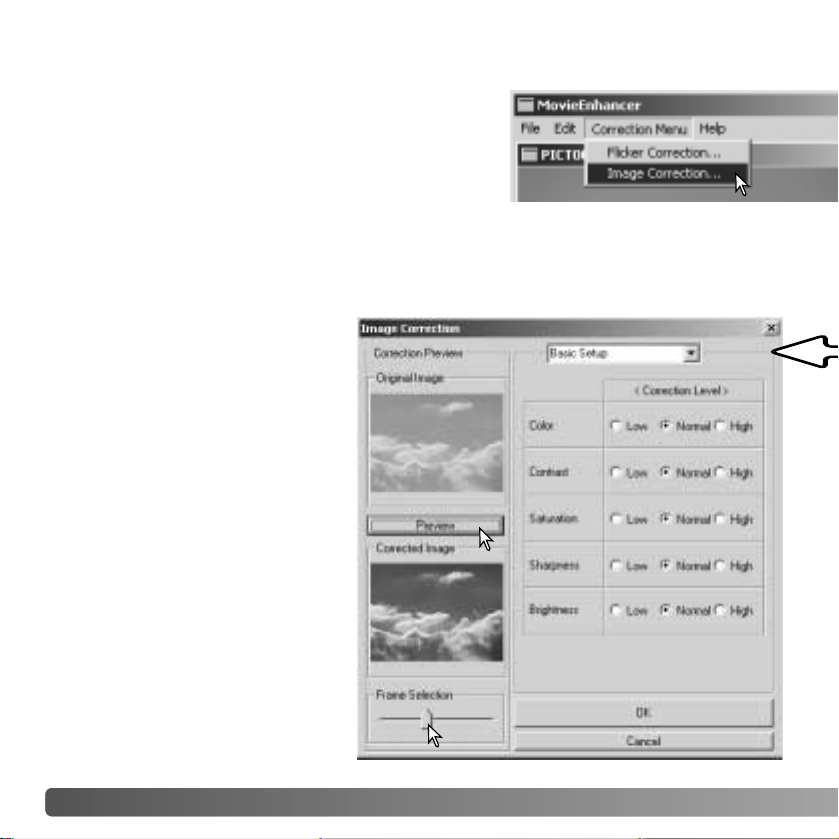
The image quality of a 640 X 480 (VGA) or smaller
movie clip can be adjusted. If both flicker correction
and image correction is applied to the same movie
clip, the flicker correction processing should be done
first. With the movie displayed in the movie enhancer,
select the image-correction option from the correction
menu to open the palette.
The drop-down menu at the top of the window switches between the the basic and
advance setup palettes. Both palettes control the same image qualities, but the advance
setup palette allows finer adjustments.
The correction-preview display
shows the original image and the
corrected image. To initially display
the corrected image, press the
preview button. Use the preview
button to update the image display
every time a setting is changed.
The frame-selection slider can
display any frame in the movie clip.
The basic setup palette allows
corrections to color, contrast,
saturation, sharpness, and
brightness in three degrees. “Low”
makes a slight adjustment to the
quality, whereas “High” makes a
large change.
78 MOVIE ENHANCER
CORRECTING MOVIE IMAGES
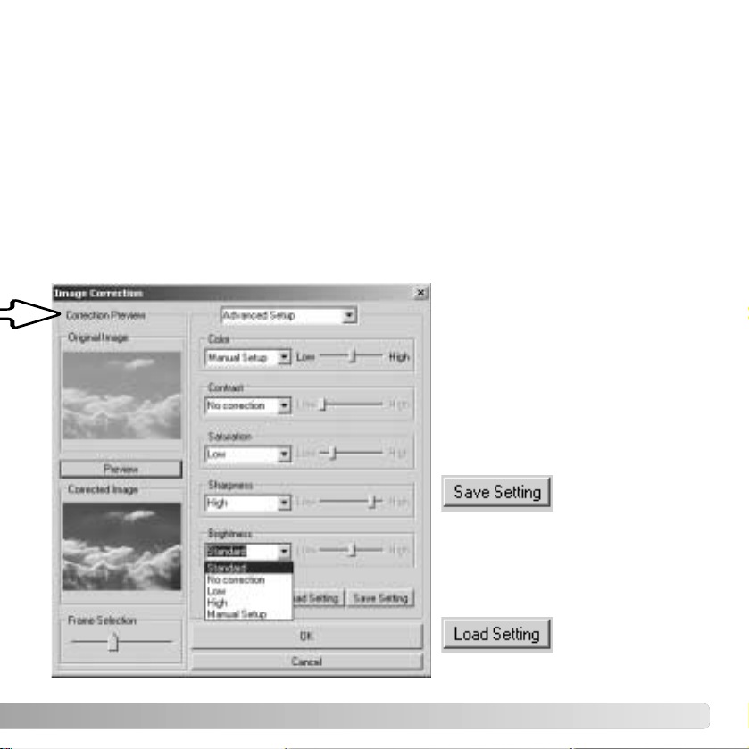
79
Color corrects the overall color cast of an image. The higher the level, the greater the
color balance is shifted toward neutral. Contrast controls the relative brightness levels.
The higher the level, the brighter the highlights and the darker the shadows. Saturation
controls the vividness of colors. Sharpness controls the sharpness of image details.
Brightness controls how bright the image is.
The advanced setup palette has five correction settings for color, contrast, saturation,
sharpness, and brightness. Selected with the drop-down menu for each of the five image
qualities, low, standard, and high are preset levels, manual setup activates the slider for
manual adjustments, and no correction turns off the correction function.
To save the current settings. Only
one set of settings can be saved.
Each time the function is used, the
previous setting are replaced with
the new ones.
To apply the last set of settings
saved.
When all settings have been made,
press the preview button to confirm
the effect on the image.
Click the OK button to begin
processing. The save dialog box
will open; rename the file and
specify the location to save it. The
file can only be saved in the MOV
format.
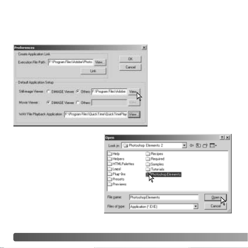
80 ADVANCED SETUP
The application software to open
still images, movie clips, and
audio files can be specified in the
preferences dialog box. To open
the dialog box, select the
preferences option from the file
menu.
The default application setup
specifies the software used to
open certain files. When a
thumbnail is double clicked in the
DiMAGE Viewer, it will be
opened in the specified
application.
ADVANCED SETUP
CUSTOMIZING THE VIEWER - PREFERENCES
The radio button indicates the
application used to open still
images and movie clips. To link a
new application, click the others
radio button and then the view
button; the open dialog box will be
displayed. Select the new
application and click the open
button. The file path will be
displayed in the preference
window. Click OK to complete the
setup.
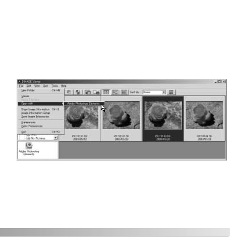
81
The create-application-link function links another image-processing application to the
DiMAGE Viewer. When the link is made, the application icon is displayed in the thumbnail
window.
To create the link, click the view button; the open dialog box will be displayed. Select the
new application and click the open button. The file path will be displayed in the
preference window. Click the link button.
Click OK to complete the operation. The application icon will be displayed in an area
below the folder tree.
To open a file in the application, drag and drop the file onto the icon or highlight the file
and select the application from the open-with option on the file menu.
To remove the application from the display, click on the icon and then use the delete
button on the tool bar or keyboard to delete it. This also resets the preference box.
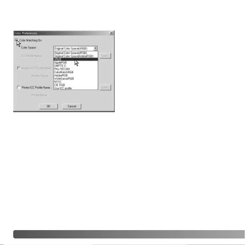
82 ADVANCED SETUP
COLOR MATCHING
- COLOR PREFERENCES
Each output device (monitor or printer) defines
color and contrast differently. To ensure
accurate reproduction, the output color space
must be defined. Color matching is used for
professional color management. It is not
needed for normal personal use.
Select the color-preferences option from the
file menu to open the dialog box.
In the dialog box, click the color-matching-on
check box.
Select a color space from the drop-down list.
The following color spaces are available:
Original Color Space (sRGB) - the color space of the camera image is not converted to
a standard color space. This color space is recommended for images captured with a
Minolta DiMAGE digital camera. The DiMAGE Viewer, monitor, and printer interprets the
color as sRGB for reproduction purposes, but does not convert the original camera color
space.
Original Color Space (Adobe RGB) - Adobe-RGB color-mode images captured with a
Minolta digital camera such as the DiMAGE 7Hi or DiMAGE A1 must be opened with this
color space unless the color profile has been embedded; see the embedded camera
profiles section on page 90. As with Original Color Space (sRGB), the color space of the
camera image is not converted to a standard color space. The DiMAGE Viewer, monitor,
and printer interprets the color as Adobe RGB for reproduction purposes, but does not
convert the original camera color space.
sRGB - the color space promoted by Hewlett Packard and Microsoft. Since it reflects the
average PC monitor characteristics, it is widely used around the world, and is considered
to be the standard for multi-media and Internet usage. sRGB is not suitable for
professional prepress applications because of its narrow reproduction range.
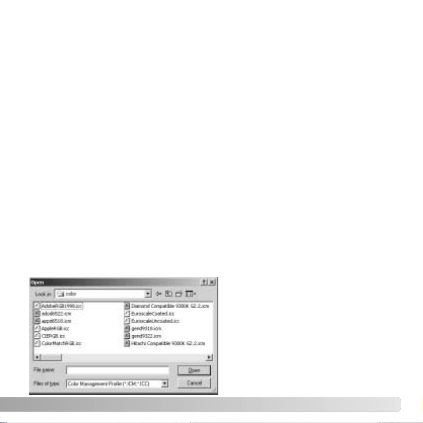
83
Apple RGB - widely used in DTP. It is the standard color space in many common graphic
arts and design applications: Adobe Illustrator, Photoshop, etc.
SMPTE-C - the current television broadcasting standard used in the United States.
PAL/SECAM - the current television broadcasting standard used in Europe.
ColorMatch RGB - this standard has a wide color space and is ideal for use with Radius
Press View monitors, which are commonly used in prepress production.
Adobe RGB - this color space is wider than ColorMatch RGB. The extensive color range
makes it ideal for prepress use. However, the range is so great that it includes many
colors that cannot be reproduced with a four-color printing process.
Wide-gamut RGB - utilizing the color coordinates of the spectrum, this standard offers
an extreme range of colors. Many of the colors that can be generated cannot be
reproduced on standard computer monitors or by printing technology.
NTSC - the current television broadcasting standard used in Japan.
CIE RGB - this color space is defined by the CIE.
Use ICC Profile - to employ a specific ICC profile.
To use a specific profile, select the use-
ICC-profile option. Click the load button
and use the open window to open the
profile; the profile name will appear in the
color-preferences window. Click the OK
button to set the color space and close
the color-preferences window.
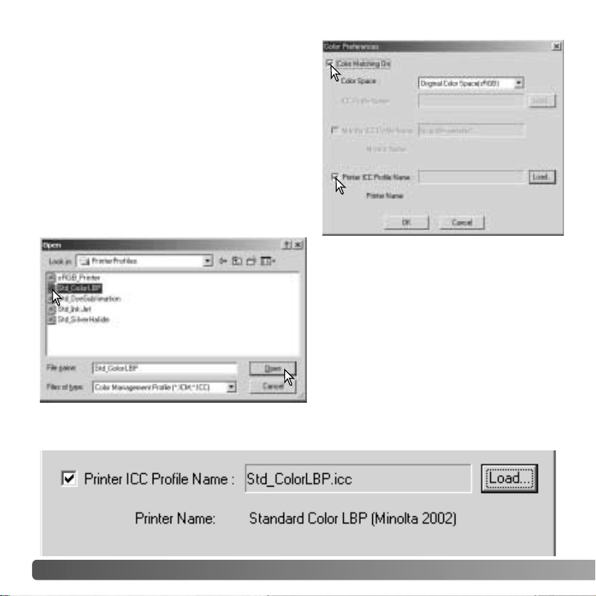
84 ADVANCED SETUP
USING PRINTER ICC PROFILES
Specific printer ICC profiles can be used with
the DiMAGE Viewer. Select the color-
preferences option from the file menu to open
the dialog box.
In the dialog box, click the color-matching-on
and printer-ICC-profile check boxes.
Click on the printer ICC profile load button to
display the open window.
Locate the ICC profile for the specific
device; for profile locations, see page 86.
Click the open button to complete the
operation.
CMY or CMYK printer profiles are not
compatible with the DiMAGE Viewer
software.
When loaded correctly, the ICC profile will be displayed in the color preference window.
The profile can be temporarily disabled by clicking on the printer-ICC-profile check box.
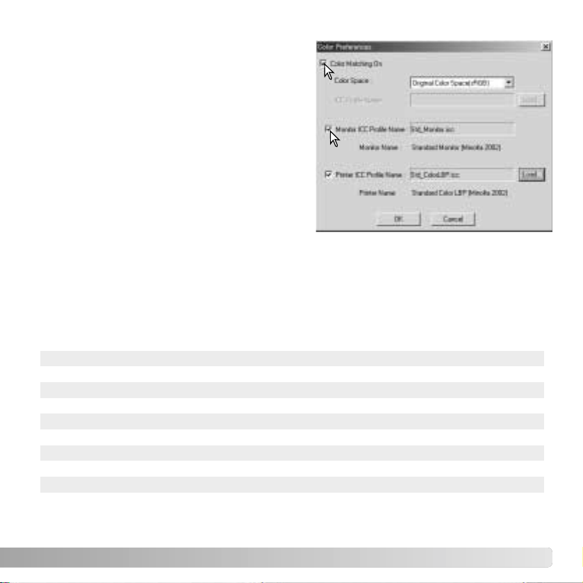
85
USING MONITOR ICC PROFILES
The computer system’s monitor ICC profiles
can be used with the DiMAGE Viewer. Select
the color-preferences option from the file menu
to open the dialog box. In the dialog box, click
the color-matching-on and monitor-ICC-profile
check boxes.
If the monitor ICC profile fields are gray, the
monitor profile has not been specified with the
operating system. Refer to your operating
system’s manual or help on how to install
monitor ICC profiles. For profile locations, see
page 86.
Generic monitor and printer profiles are supplied with the DiMAGE Viewer. In Windows,
the profiles folder is located in the DiMAGE Viewer application folder. The profiles are in
the following location in a Macintosh: [System]>[Preferences]>[7300]>[Profiles]; or for
Mac OS X: [Library]>[Preferences]>[7300]>[Profiles].
Std_Monitor.icc
sRGB_Monitor.icc
Printer profiles
sRGB_Printer.icc
Std_ColorLBP.icc
Std_DyeSublimation.icc
Std_InkJet.icc
Std_SilverHalide.icc
For average monitors.
For Windows sRGB monitors.
For printers which use sRGB color space.
For color laser printers.
For dye-sublimation printers.
For inkjet printers.
For silver-halide dye-transfer printers.
Monitor profiles
Apple_Monitor.icc For Apple monitors.
ABOUT DiMAGE VIEWER ICC PROFILES
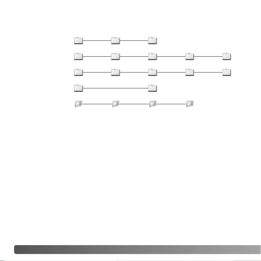
86 ADVANCED SETUP
ICC profiles for a specific monitors or printers are available from the manufacturer. These
may be downloaded from the manufacturer’s web site. See the instruction manual of the
specific device on how to install the ICC profile.
ICC PROFILE LOCATIONS
ICC profiles can be found in the following locations:
Windows
Windows
98, 98SE, Me
System Color
Windows XP
Mac OS 9
Mac OS X
System32
System folder
Library
Windows Spool Drivers Colors
System32WINNT Spool Drivers Colors
ColorSync profile folder
ColorSync Profiles Displays
Windows 2000
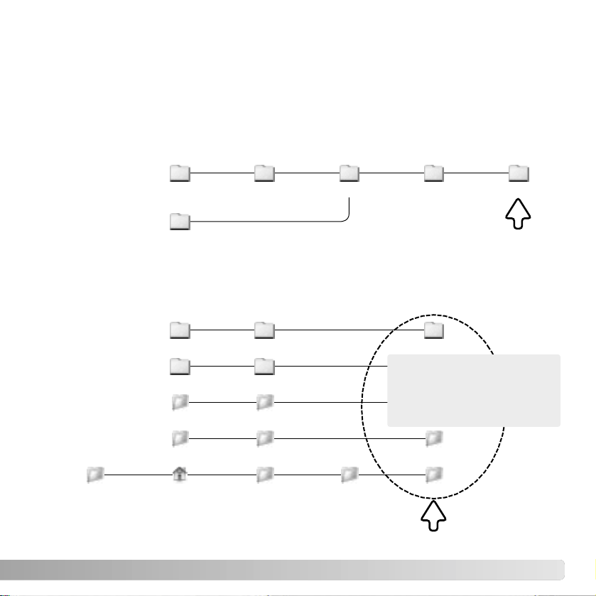
87
VIEWER NOTES
UNINSTALLING THE DiMAGE VIEWER
Windows
Uninstall the the DiMAGE Viewer using the add/remove programs or add/remove
applications (XP) routine in the control panel. Afterwards, place the 7300 folder in the
trash and empty it to complete the operation. The folder contains the Job files.
Macintosh
As well as the DiMAGE Viewer application folder, the following files and folders should
also be deleted:
System
Mac OS 9
Preferences
PreferencesLibrary
7300
System Extensions
CFMSupportLibrary
Mac OS X
DSCIPLibrary2
MQTQueenLib MQueenLib
MCMLibraryDSC2
MQTQueenLib2 MQueenLib2
7300
Users Logon name Library
Preferences 7300
Delete
Windows 98,
98SE, and Me
Windows
(Logon name)Documents and
settings
Application data DiMAGE 7300
Windows 2000
and XP
Delete

88 VIEWER NOTES
Windows
If you are upgrading the DiMAGE Viewer from a version earlier than 2.2, the following
procedure can be used to copy Job files from the old application to the new one. This is
not necessary for Macintosh OS 9 operating systems.
COPYING JOB FILES
1. Log on to your computer as an administrator. Open the DiMAGE Viewer application
folder. If the standard installation was used, it will be located in C:\Program
Files\DiMAGE Viewer. Letters designating the hard drive can vary between
computers.
2. Copy the Prefs folder into another folder in a different location. Example,
C:\Job_Move.
3. Uninstall the old version of the DiMAGE Viewer using the add/remove programs or
add/remove applications (XP) routine in the control panel.
4. Install the new DiMAGE Viewer. See page 8.
5. While logging on as a user, launch the DiMAGE Viewer once and close it to create
the necessary folders.
6. Open the Prefs folder that was copied from the old DiMAGE Viewer application to
show the ImageCorrectJob and MRWCorrectJob folders.
7. Copy all the files in the ImageCorrectJob folder with an .icj extension to the following
location:
Windows XP/2000: C:Document and Settings \ (Logon user name) \ ApplicationData
\ DiMAGE \ 7300 \ Prefs \ ImageCorrectJob.
Windows 98/98SE/Me: C:\ Windows \ ApplicationData \ DiMAGE \ 7300 \ Prefs \
ImageCorrectJob.

89
Macintosh OS X
1. Log on to your computer an administrator. Open the 7300 folder: /Library/
Preferences/7300.
2. Copy the Prefs folder into another folder in a different location. Example, /Job_Move.
3. Delete the old DiMAGE Viewer application folder.
4. Install the new DiMAGE Viewer. See page 10.
5. While logging on as a user, launch the DiMAGE Viewer once and close it to create
the necessary folders.
6. Open the Prefs folder that was copied from the old DiMAGE Viewer application. Copy
all the files with an .icj and .mrj extension to the following location: /Users/(logon user
name)/Library/Preferences/7300/Prefs.
7. Open the DiMAGE Viewer to confirm the Jobs can be loaded.
8. Copy the MRWCorrectJob folder to the following location:
Windows XP/2000: C:Document and Settings \ (Logon user name) \ ApplicationData
\ DiMAGE \ 7300 \ Prefs.
Windows 98/98SE/Me: C:\ Windows \ ApplicationData \ DiMAGE \ 7300 \ Prefs.
9. Open the DiMAGE Viewer to confirm the Jobs can be loaded.

90 ADVANCED SETUP
Minolta, The essentials of imaging, and DiMAGE are trademarks or registered trademarks of
Minolta Co., Ltd. Microsoft and Windows are registered trademarks in the United States and
other countries of Microsoft Corporation. The official name of Windows is Microsoft Windows
Operating System. Pentium is a registered trademark of Intel Corporation. Apple, the Apple logo,
Macintosh, Power Macintosh, Mac OS and the Mac OS logo are registered trademarks of Apple
Computer, Inc. All other brand and product names are are trademarks or registered trademarks
of their respective owners.
NOTES ON COLOR MEASUREMENT
When opening a Minolta-RAW image (p. 68), color information recorded on location with
a Minolta color meter can be used to set the white balance of the image. If the image is
captured under a continuous source like the sun or tungsten lighting, the corresponding
measurement can be very effective in balancing the color of the image. However,
because the spectral response of the camera’s CCD and the color meter are not the
same, if images are captured under lighting with a discontinuous line spectrum like
fluorescent or mercury vapor, the values recorded with the color meter may not result in
an accurate reproduction.
EMBEDDED CAMERA COLOR PROFILES
Certain Minolta digital cameras, such as the DiMAGE 7Hi or DiMAGE A1, can embed the
camera’s color profile into the image data for color matching. The color mode on the
camera determines the profile: sRGB, used with Natural and Vivid Color, or Adobe RGB.
By setting the color space to either Original Color Space (sRGB) or Original Color Space
(Adobe RGB) in the color preference window, the DiMAGE Viewer can determine the
color space embedded in the image and adjust accordingly. If the color space is not
embedded in the image, the color space must be set manually for both color spaces, see
color matching on page 82.
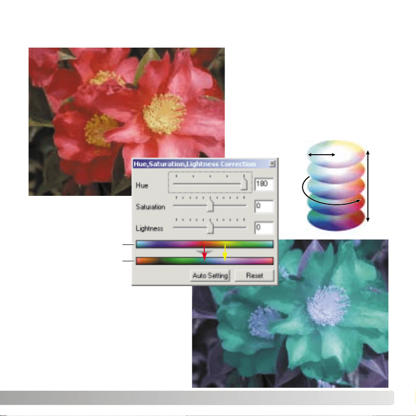
91
Changes in hue rotate the original
color values though a color space and
reassigns a new hue depending on
the new position in the color space. In
this example, the original image was
rotated 180° through the color space.
For more on the hue, saturation, and
brightness palette, see page 60.
HUE CORRECTION EXAMPLE
Two color spaces are displayed at the
bottom of the palette. The top bar
indicates the color space of the
original image. The bottom bar
displays the relative shift to the color
space. In the example, the reds have
been shifted to cyan and the yellows to
lavender.
Original color space
New color space
Saturation
Lightness
Hue

©2003 Minolta Co., Ltd. under the Berne Convention and the Universal Copyright Convention.
Printed in Japan
9222-7300-41 SY-A306
1AG6P1P1616--
2.2.0
Minolta Co., Ltd. 3-13, 2-Chome, Azuchi-Machi, Chuo-Ku, Osaka 541-8556, Japan
Minolta Europe GmbH Minoltaring 11, D-30855 Langenhagen, Germany
Reparatur/Repair Senator-Helmken-Strasse 1, D-28197 Bremen, Germany
Minolta France S.A.S. 365 Route de Saint-Germain, F-78420 Carrieres-Sur-Seine, France
Minolta (UK) Limited 7 Tanners Drive, Blakelands, Milton Keynes, MK14 5BU, England
Minolta Austria Ges. m.b.H. Amalienstrasse 59-61, A-1131 Wien, Austria
Minolta Camera Benelux B.V. Zonnebaan 39, P.O. Box 6000, NL-3600 HA Maarssen, The Netherlands
Belgian Branch Prins Boudewijnlaan 1, B-2550 Kontich, Belgium
Minolta (Schweiz) AG Riedstrasse 6, CH-8953 Dietikon, Switzerland
Minolta Svenska AB Albygatan 114, S-171 54 Solna, Sweden
Finnish Branch Niittykatu 6 PL 37, SF-02201 Espoo, Finland
Minolta Portugal Limitada Av. do Brasil 33-A, P-1700 Lisboa, Portugal
Minolta Corporation 101 Williams Drive, Ramsey, New Jersey 07446, U.S.A.
Minolta Canada Inc. 369 Britannia Road East, Mississauga, Ontario L4Z 2H5, Canada
Minolta Hong Kong Limited Room 208, 2/F, Eastern Center, 1065 King’s Road, Quarry Bay, Hong Kong
Minolta Singapore (Pte) Ltd. 10, Teban Gardens Crescent, Singapore 608923
Shanghai Minolta Optical
Products Co., Ltd. 368 Minolta Road, Songjiang, Shanghai, China