Loading ...
Loading ...
Loading ...
Attaching the Bass boost
remote control
Attach with tapping screws (3 mm × 10 mm
(1/8 in. × 3/8 in.)) at an easily accessible loca-
tion such as under the dashboard.
Tapping screws (3 mm × 10 mm (1/8 in. × 3/
8 in.))
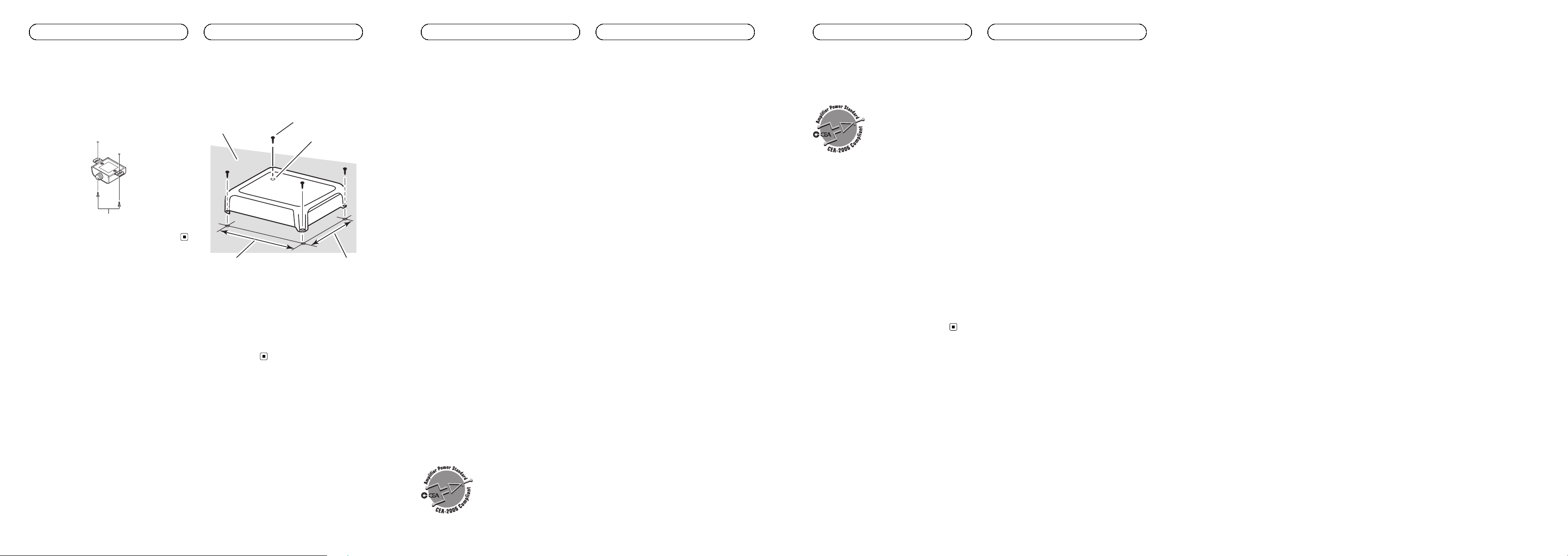
Example of installation on
the floor mat or chassis
1 Place the amplifier in the desired instal-
lation location.
Insert the supplied tapping screws (4 mm ×
18 mm (5/32 in. × 3/4 in.)) into the screw holes
and push on the screws with a screwdriver so
they make an imprint where the installation
holes are to be located.
2 Drill 2.5 mm (3/32 in.) diameter holes at
the imprints either on the carpet or directly
on the chassis.
3 Install the amplifier with the use of
supplied tapping screws (4 mm × 18 mm
(5/32 in. × 3/4 in.)).
1
2
3
45
1 Tapping-screws (4 mm × 18 mm (5/32 in. ×
3/4 in.))
2 Drill a 2.5 mm (3/32 in.) diameter hole.
3 Floor mat or chassis
4 Hole-to-hole distance: 229.5 mm (9-1/32 in.)
(GM-D8701 and GM-DX871) / 279.5 mm
(11 in.) (GM-D9701 and GM-DX971)
5 Hole-to-hole distance: 191.5 mm
(7-17/32 in.)
<5707000012760V>13
En
Installation
Specifications
GM-D8701 and GM-DX871
Power source ............................. 14.4 V DC (10.8 V to 15.1 V
allowable)
Grounding system ................... Negative type
Current consumption ............ 22 A (at continuous power,
4 W)
Average current consumption
..................................................... 2.4 A (4 W for one channel)
3.6 A (2 W for one channel)
5.7 A (1 W for one channel)
Fuse ................................................ 40 A × 2
Dimensions (W × H × D) ... 252 mm × 60 mm ×
215 mm
(9-7/8 in. × 2-3/8 in. ×
8-1/2 in.)
Weight .......................................... 2.7 kg (6 lbs)
(Leads for wiring not in-
cluded)
Maximum power output ....... 600 W × 1 (4 W)/1600W×
1 (1 W)
Continuous power output ...300 W × 1 (at 14.4 V, 4 W,
20 Hz to 240 Hz, ≦ 1 % THD)
500 W × 1 (at 14.4 V, 2 W,
100 Hz, ≦ 1 % THD)
800 W × 1 (at 14.4 V, 1 W,
100 Hz, ≦ 1 % THD)
Load impedance ...................... 4 W (1 W to 8 W allowable)
Frequency response ............... 10 Hz to 240 Hz (+0 dB,
–3 dB)
Signal-to-noise ratio ............... 100 dB (IHF-A network)
Low pass filter:
Cut off frequency ........... 40 Hz to 240 Hz
Cut off slope ..................... –12 dB/oct
Bass boost:
Frequency .......................... 50 Hz
Level ..................................... 0 dB to 18 dB
Gain control:
RCA ...................................... 200 mV to 6.5 V
Speaker .............................. 0.8 V to 16 V
Maximum input level / impedance:
RCA ...................................... 6.5 V / 25 kW
Speaker .............................. 16 V / 12 kW
CEA2006 Specifications
Power output ............................. 300 W RMS × 1 Channel (at
14.4 V, 4 W, 20 Hz to 240 Hz
and ≦ 1 % THD+N)
500 W RMS × 1 Channel (at
14.4 V, 2 W, 100 Hz and ≦ 1%
THD+N)
800 W RMS × 1 Channel (at
14.4 V, 1 W, 100 Hz and ≦ 1%
THD+N)
S/N ratio ....................................... 75 dBA (reference: 1 W into
4 W)
GM-D9701 and GM-DX971
Power source ............................. 14.4 V DC (10.8 V to 15.1 V
allowable)
Grounding system ................... Negative type
Current consumption ............ 38 A (at continuous power,
4 W)
Average current consumption
..................................................... 3.5 A (4 W for one channel)
5.1 A (2 W for one channel)
7.5 A (1 W for one channel)
Fuse ................................................ 40 A × 3
Dimensions (W × H × D) ... 302 mm × 60 mm ×
215 mm
(11-7/8 in. × 2-3/8 in. ×
8-1/2 in.)
Weight .......................................... 3.1 kg (6.8 lbs)
(Leads for wiring not in-
cluded)
Maximum power output ....... 1 000 W × 1 (4 W) / 2 400 W
×1(1W)
Continuous power output ...500 W × 1 (at 14.4 V, 4 W,
20 Hz to 240 Hz, ≦ 1 % THD)
800 W × 1 (at 14.4 V, 2 W,
100 Hz, ≦ 1 % THD)
1 200 W × 1 (at 14.4 V, 1 W,
100 Hz, ≦ 1 % THD)
Load impedance ...................... 4 W (1 W to 8 W allowable)
Frequency response ............... 10 Hz to 240 Hz (+0 dB,
–3 dB)
Signal-to-noise ratio ............... 100 dB (IHF-A network)
Low pass filter:
Cut off frequency ........... 40 Hz to 240 Hz
Cut off slope ..................... –12 dB/oct
Bass boost:
Frequency .......................... 50 Hz
Level ..................................... 0 dB to 18 dB
Gain control:
RCA ...................................... 200 mV to 6.5 V
Speaker .............................. 0.8 V to 16 V
Maximum input level / impedance:
RCA ...................................... 6.5 V / 25 kW
<5707000012760V>14
En
Additional information
Speaker .............................. 16 V / 12 kW
CEA2006 Specifications
Power output ............................. 500 W RMS × 1 Channel (at
14.4 V, 4 W, 20 Hz to 240 Hz
and ≦ 1 % THD+N)
800 W RMS × 1 Channel (at
14.4 V, 2 W, 100 Hz and ≦ 1%
THD+N)
1 200 W RMS × 1 Channel
(at 14.4 V, 1 W, 100 Hz and ≦
1 % THD+N)
S/N ratio ....................................... 75 dBA (reference: 1 W into
4 W)
Notes
! Specifications and the design are subject to
modifications without notice.
! The average current consumption is nearly
the maximum current consumption by this
unit when an audio signal is input. Use this
value when working out total current con-
sumption by multiple power amplifiers.
<5707000012760V>15
En
Additional information
Loading ...
Loading ...
Loading ...