
OWNER’S MANUAL
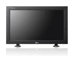
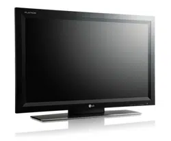
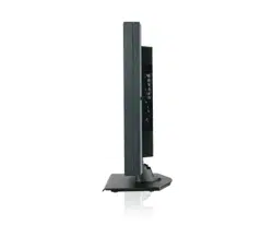
MONITOR SIGNAGE
MONITOR SIGNAGE MODELS
M4224C
M4224F
www.lge.com
Please read this manual carefully before operating
your set and retain it for future reference.
1
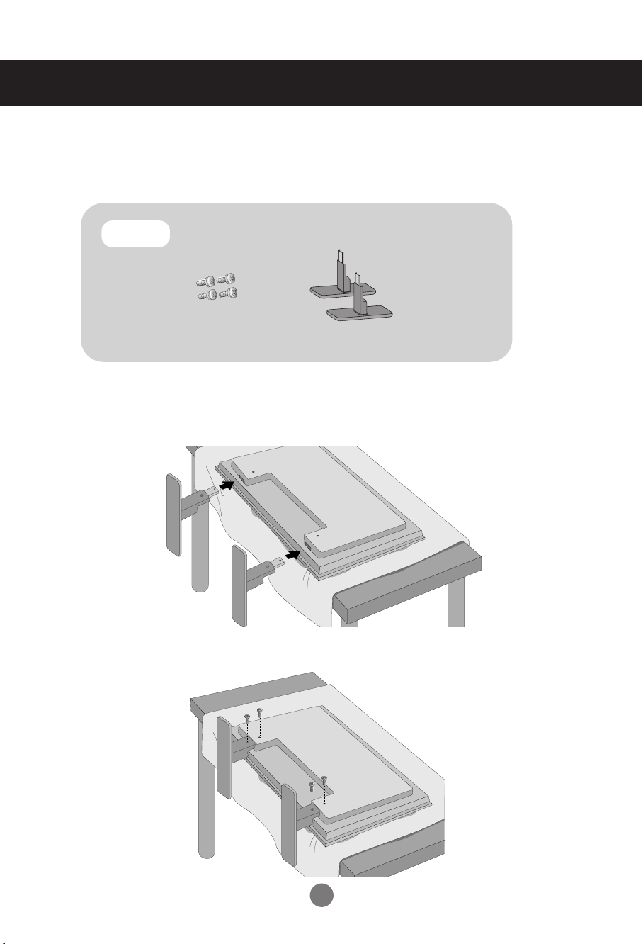
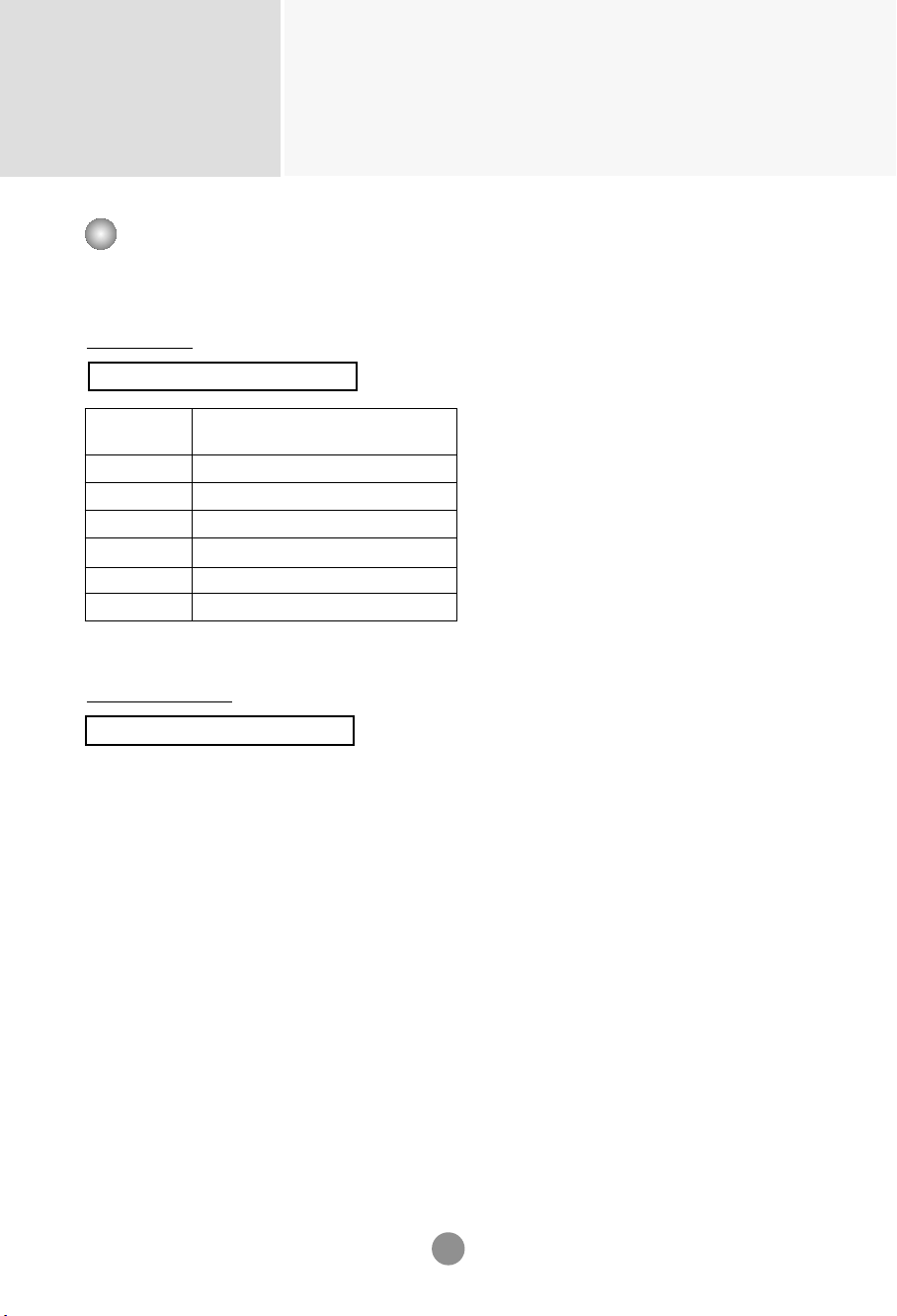
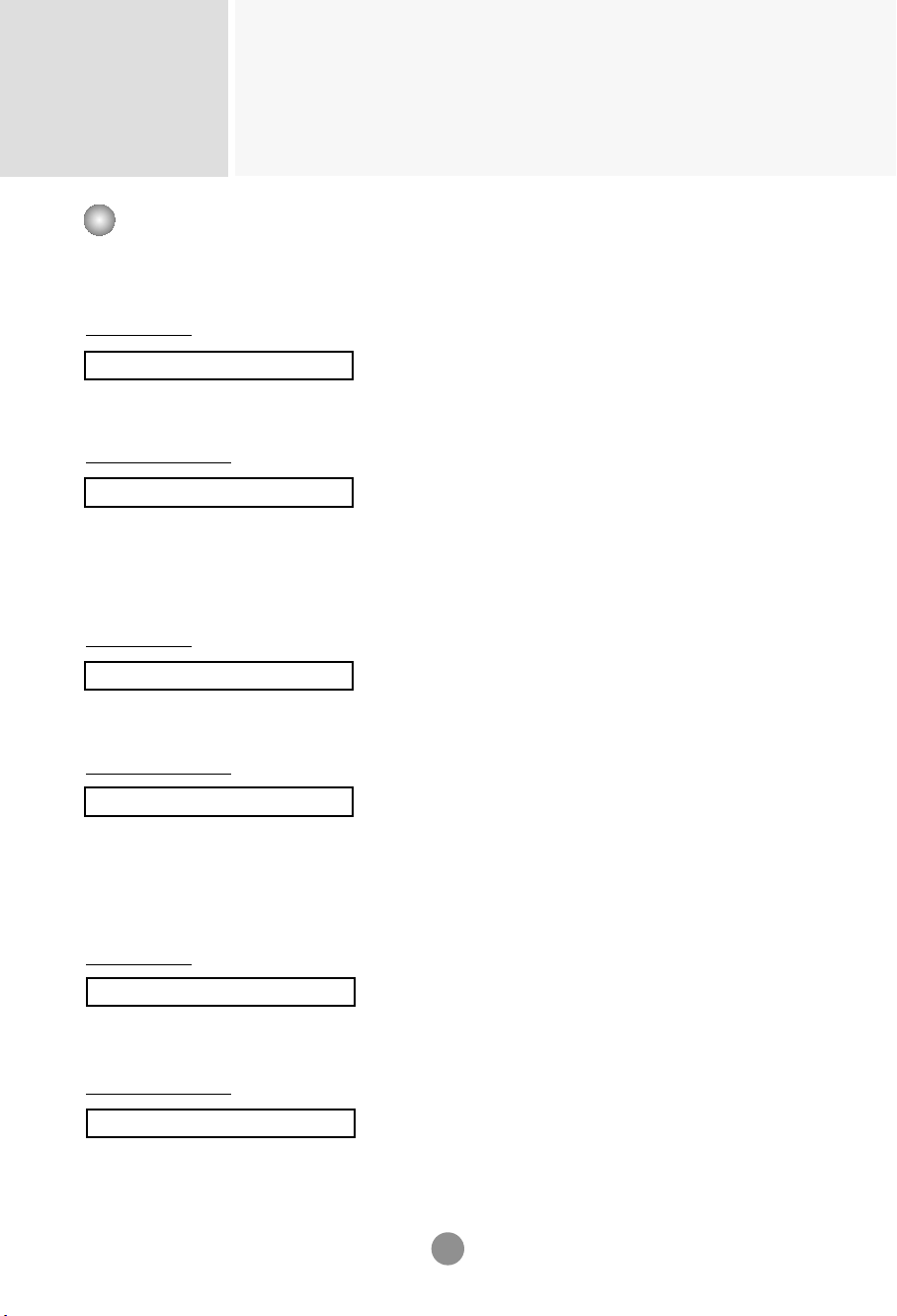
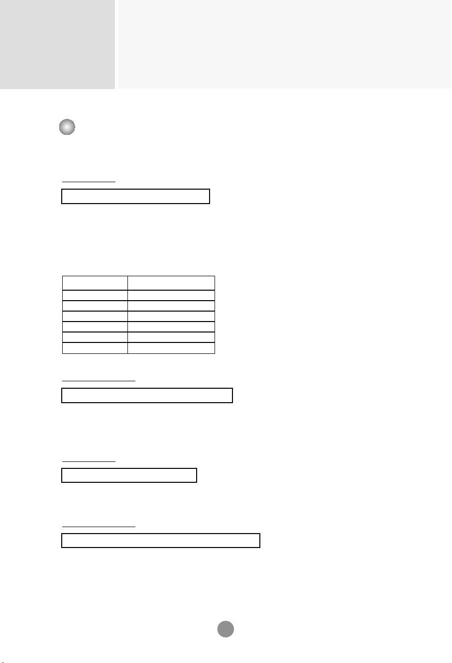
First, check if the following parts are all present.
Stand (2)
Screws (4)
Parts
1. Take the parts for the stand out of the box and assemble them as shown in the
picture.
2. Place a soft cloth on the table and put the product with the screen facing
downward. Connect the stand as shown in the following picture.
- Only on some models.
3. Use the screws to secure the stand on the rear side of the product as shown in the
diagram.
Connecting
the stand
2
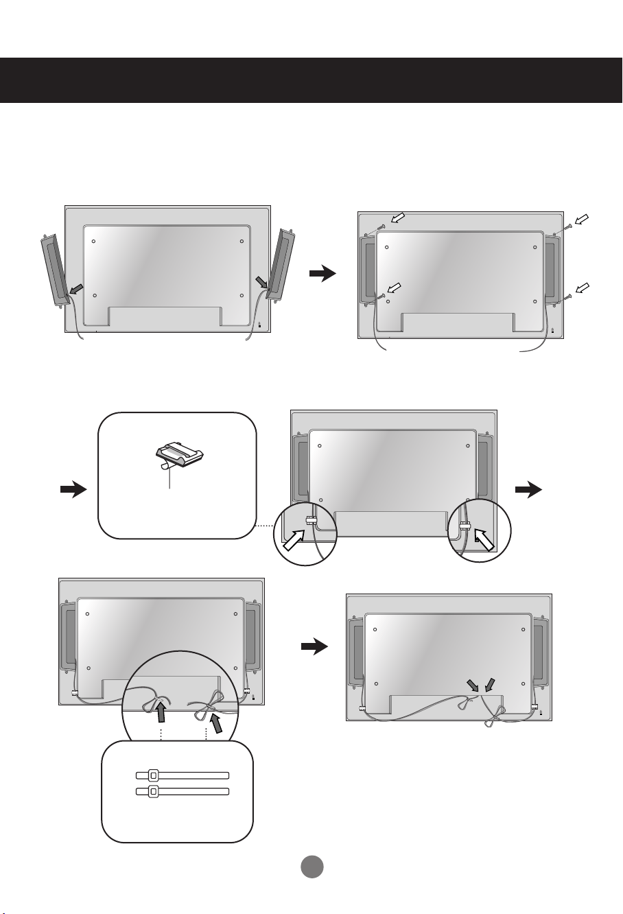
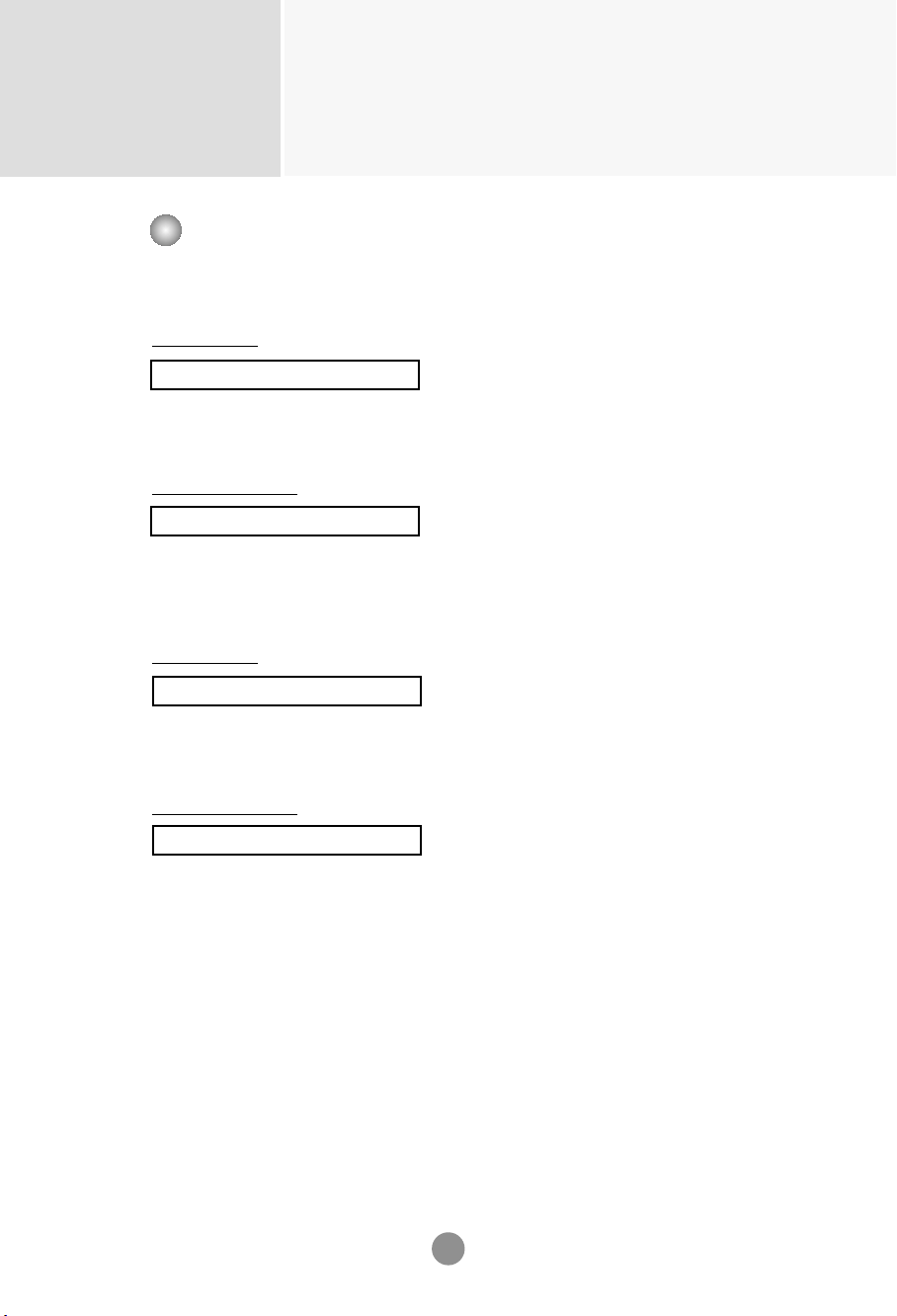
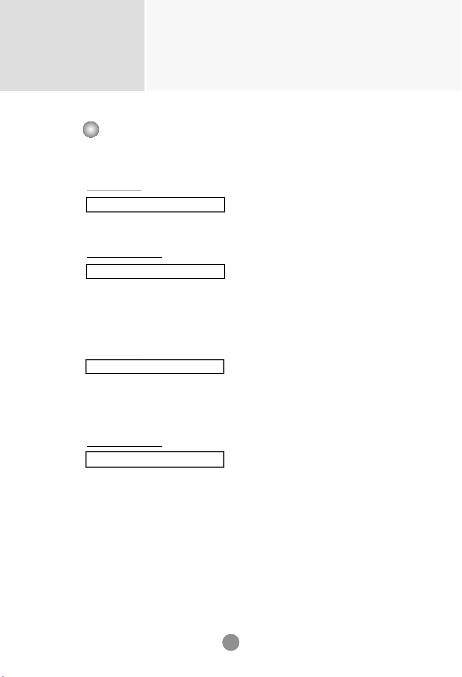
Connecting the Speakers
Mount the product onto the speaker by using a screw as shown in the following
connect the speaker cable.
- Only on some models.
When the speaker is installed.
*Connect the input terminal with a proper color match.
Remove the paper.
Cable holder
After installing your speakers, use holders and cable ties to organize the speaker cables.
* This feature is not available in all model.
Cable tie
* This feature is not available in all model.
3
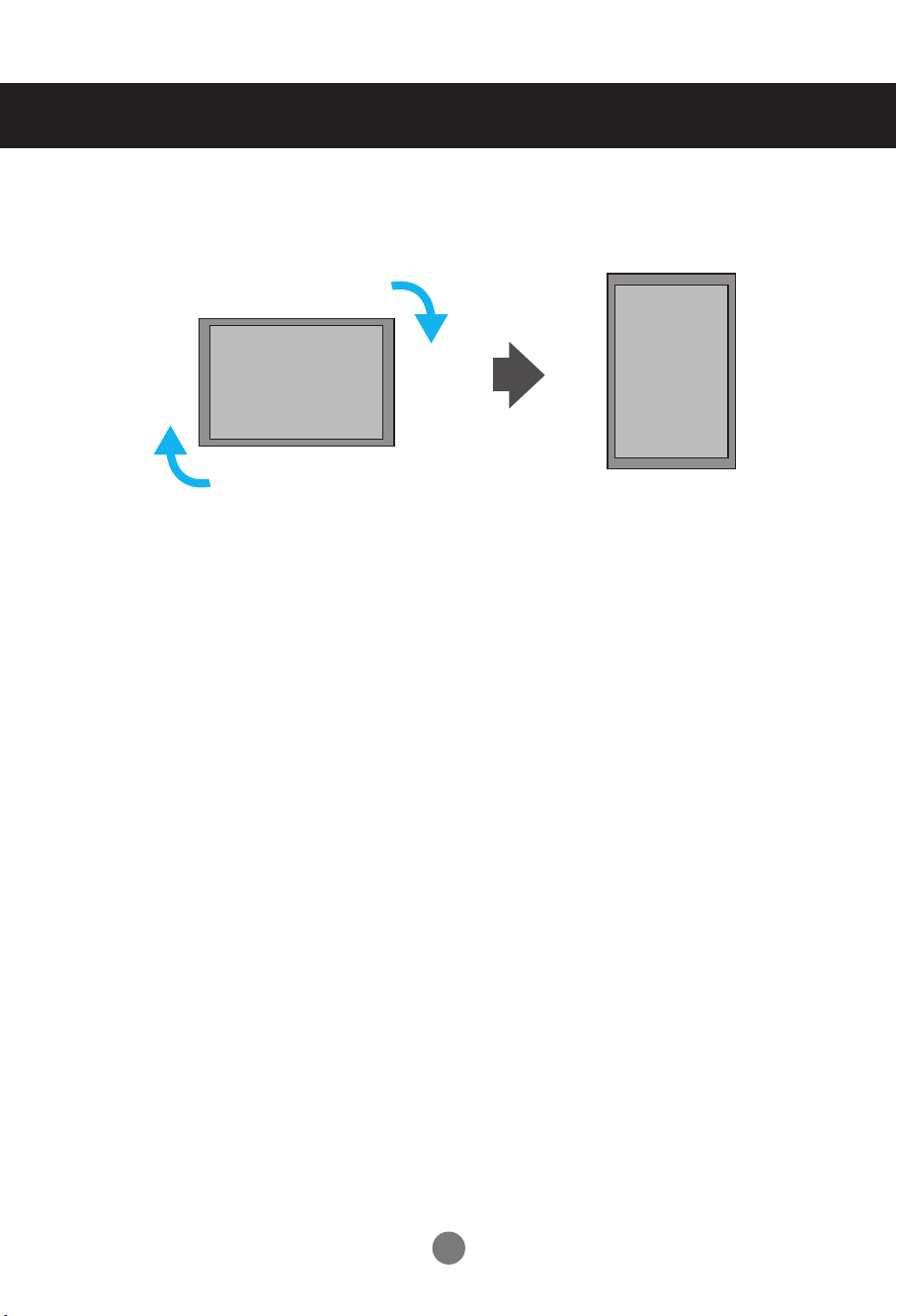
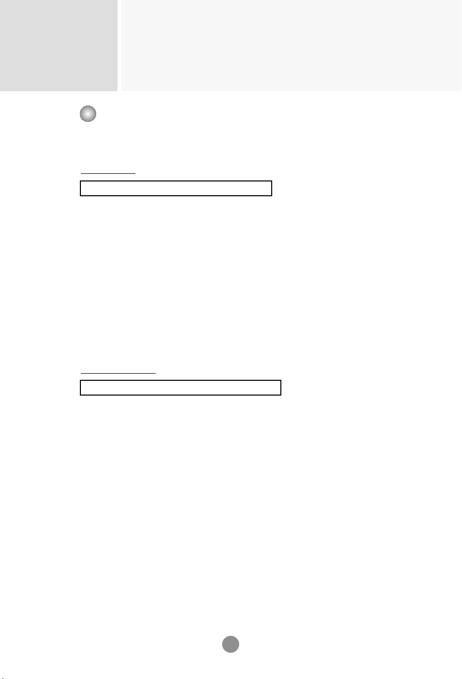
To install Portrait
- Only on some models.
"When installing Portrait, rotate it clockwise based on its front."
4
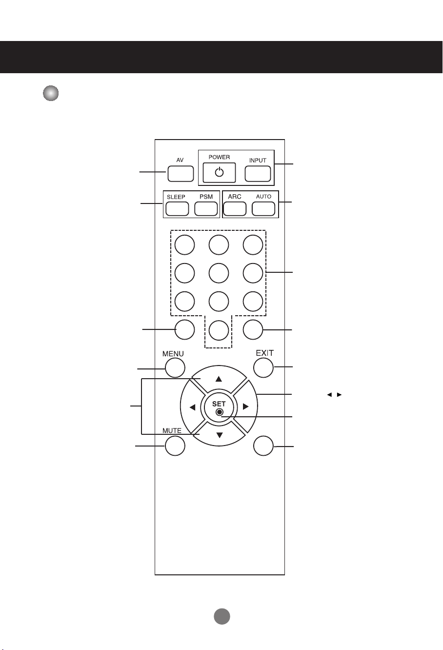
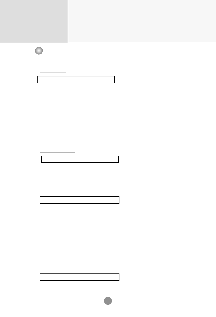
Using the Remote Control
Name of the Remote Control Buttons
1 2 3
4 5 6
7 8
0
9
*
•
AV Button
•
Sleep Button
When watching AV, RGB PC,HDMI/DVI,
Component
The product will be automatically turned
off after a certain period of time.
Press this button repetitively to
select an appropriate time duration
•
PSM Button
- Toggles through preset video
settings.
•
Menu Button
SET
Button
•
Volume Button
Volume up and down
•
Mute button
There is not a function
which is supported
•
UP and Down buttons
Bring up and down direction
adjustment.
•
ARC button
Aspect Ratio Correction. Toggles
through aspect ratio options.
•
Auto Button
Automatic adjustment function
(Operational for the analog signal only)
•
Exit Button
There is not a function
which is supported
There is not a function
which is supported
There is not a function
which is supported
•
Power On/Off Button
•
Input Select Button
(See next page)
5
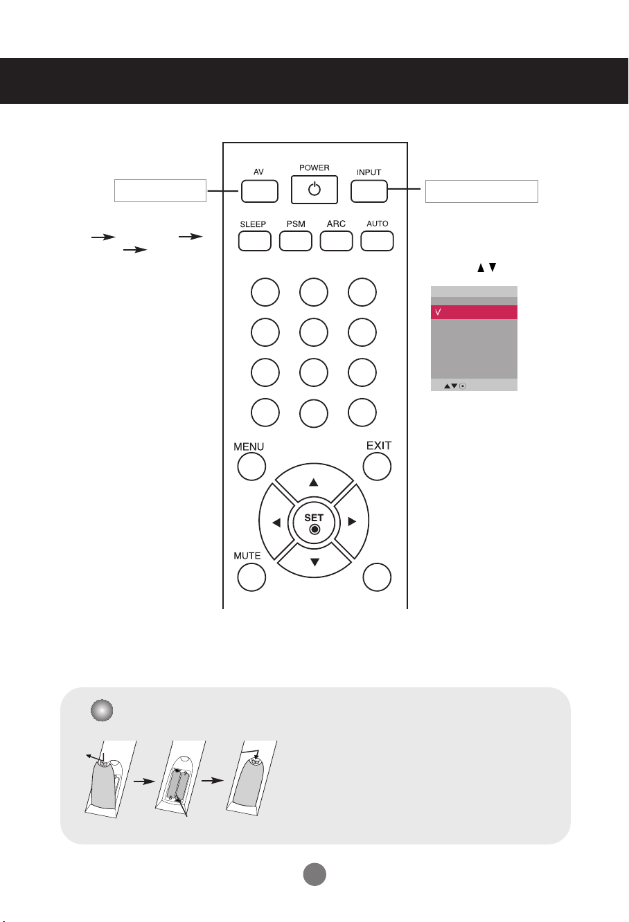
Using the Remote Control
•
AV Button
1 2 3
4 5 6
7 8
0
9
*
If you press the button once,
the following Input Signal
Window will appear. Select
the signal type you want
using the button.
•
Input Select Button
1. Slide off the battery cover.
2. Insert the batteries with correct polarity (+/-).
3. Close the battery cover.
• Dispose of used batteries in the recycle bin to prevent
environmental pollution.
Inserting batteries into remote control.
AAA Type
Input
AV
Component
RGB PC
HDMI/DVI
AV Component
RGB PC HDMI/DVI
Toggles through video
6
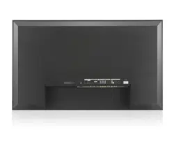
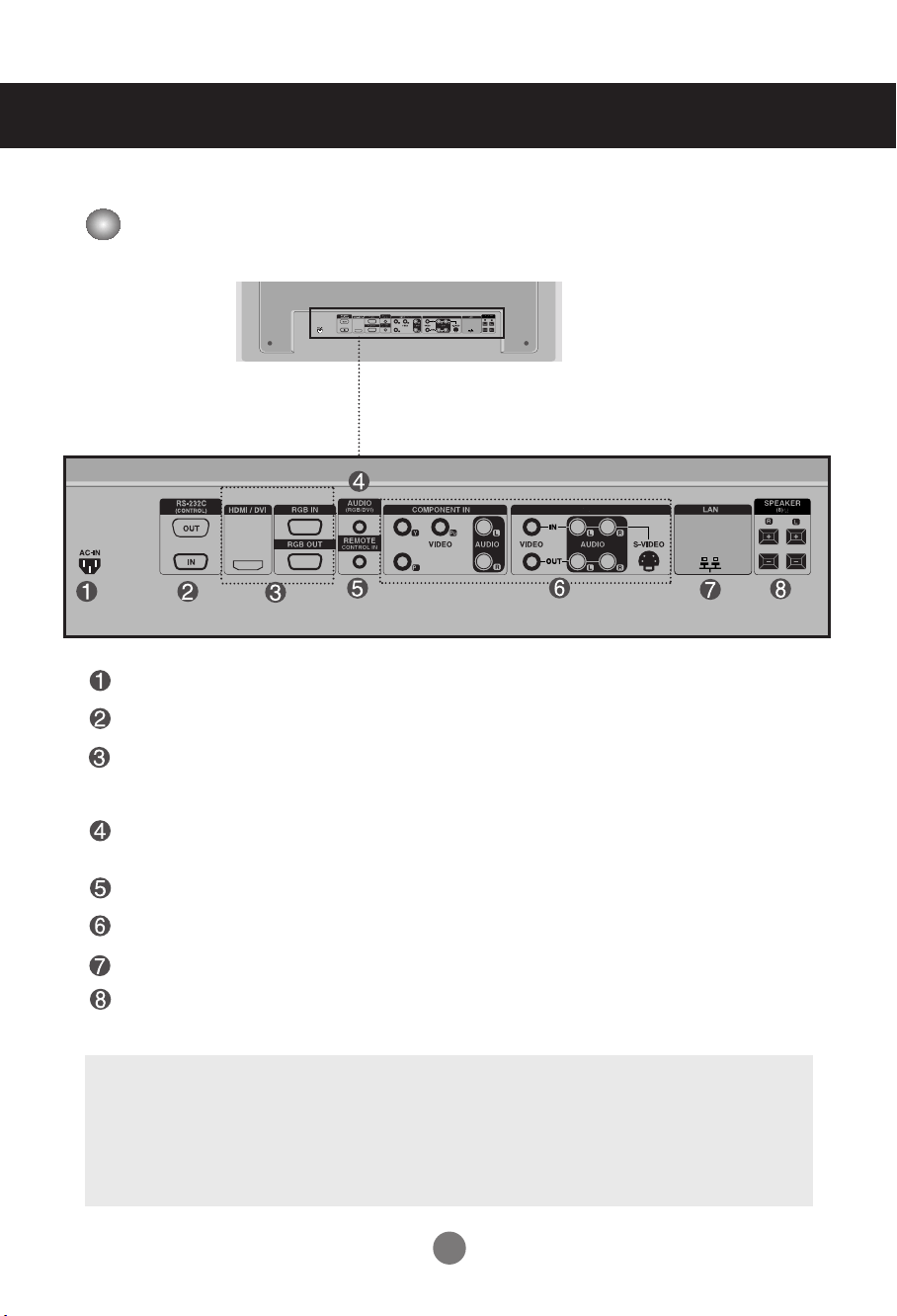
Name and Function of the Parts
Rear View
*LINE OUT
A terminal used to connect to the speaker including a built-in amplifier (Amp). Make sure that
the connecting terminal of the PC sound card is checked before connecting. If the Audio Out of
PC sound card has only Speaker Out, reduce the PC volume.
If the Audio Out of the PC sound card supports both Speaker Out and Line Out, convert to Line Out using
the card jumper of the program (Refer to the Sound Card Manual).
* The product image in the user’s guide could be different from the actual image.
Power Connector : Connect the power cord
RS-232C Serial Ports
RGB PC, HDMI/DVI Ports
-HDMI Supports High Definition input and HDCP (High-bandwidth Digital Content
Protection). Some devices require HDCP in order to display HD signals.
PC Sound Jack
: Connect the audio cable to the *LINE OUT jack of the PC sound card.
Wired Remote Control Port
AV Ports
LAN Port
Speaker Ports
AV IN/OUT
AV IN/OUT
AV IN/OUT
7
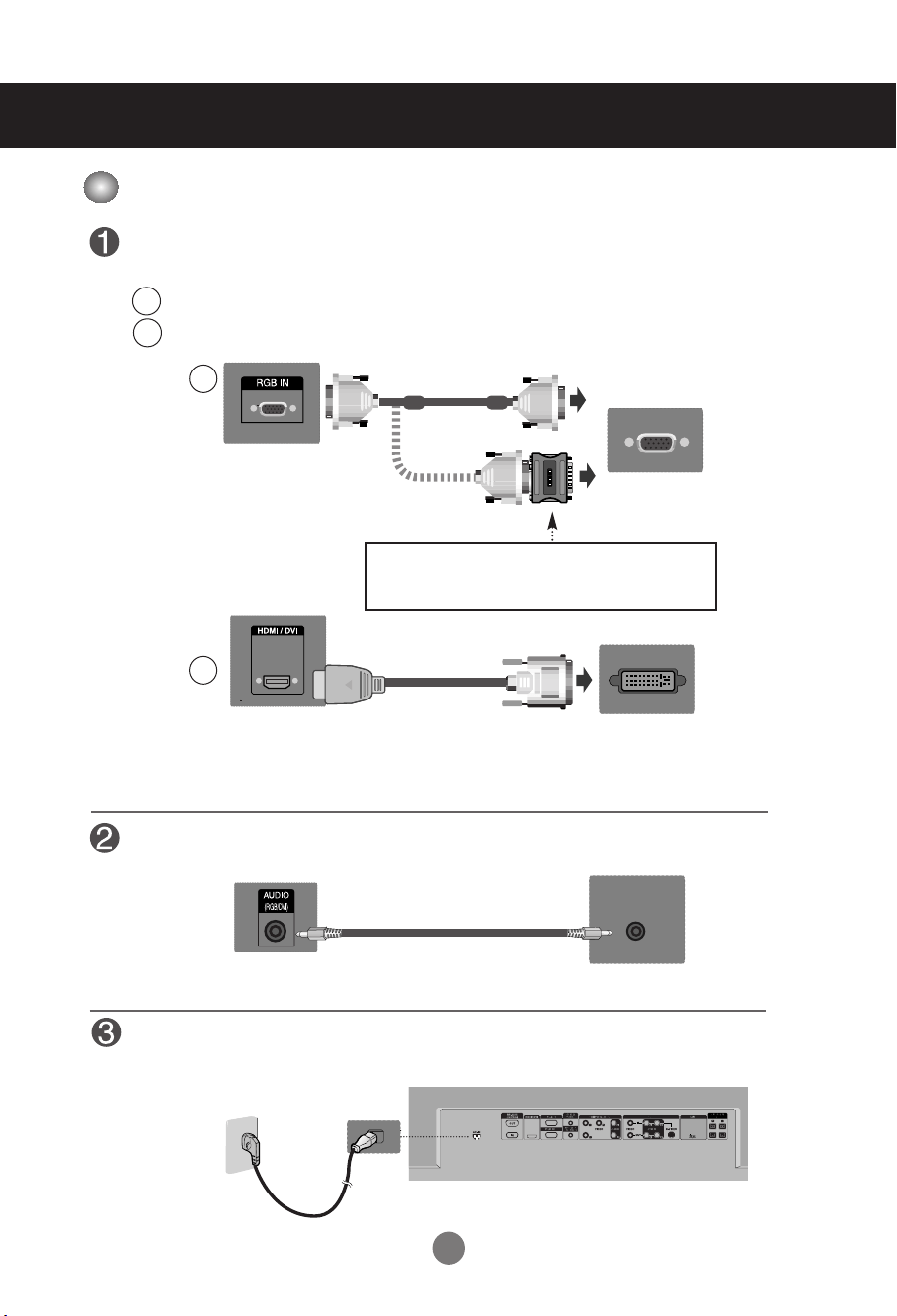
First of all, see if the computer, product and the peripherals are turned off.
Then, connect the signal input cable.
When connecting with the D-Sub signal input cable.
When connecting with the HDMI to DVI signal input cable (not included).
MAC
Macintosh Adapter (not included)
Use the standard Macintosh adapter since an incompatible
adapter is available in the market. (Different signaling system)
Rear side of the product.
Connecting to External Devices
Connect the power cord.
B
A
B
A
PC
PC/
MAC
PC
Rear side of the product.
Rear side of the product.
PC
Rear side of the product.
Connect the Audio cable.
(not included)
* User must use shielded signal interface cables (D-sub 15 pin cable, DVI cable) with ferrite cores to maintain
standard compliance for the product.
When Connecting to your PC
8
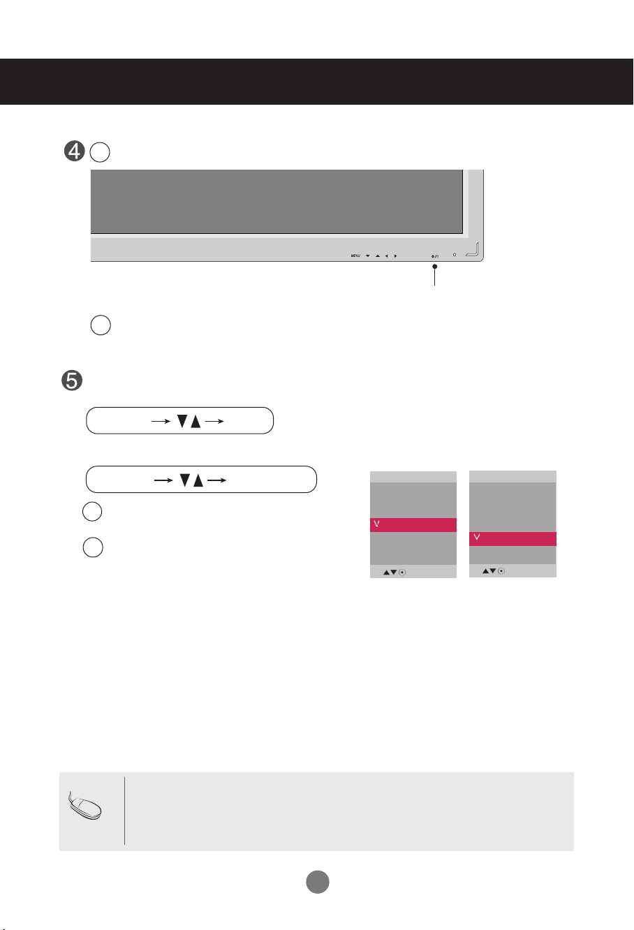
Select an input signal.
Press the INPUT button on the remote control to select the input signal.
Or, press the SOURCE button on the back of the product.
INPUT SET
•
How to connect to two computers.
Connect the signal cables (
HDMI to DVI and D-Sub) to each computer.
Press the INPUT button on the remote control to select the computer to use.
•
Directly connect to a grounded power outlet on the wall or a power bar with a ground
wire.
Note
Turn on power by pressing the power button on the product.
Turn on the PC.
AUTO/SET
SOURCE
Power button
SOURCE
AUTO/SET
When connecting with a D-Sub signal input cable.
• Select RGB PC : 15-pin
D-Sub
analog signal.
When connecting with a HDMI to DVI signal input cable.
• Select HDMI/DVI :
HDMI to DVI
Digital signal.
B
A
Connecting to External Devices
2
1
Input
AV
Component
RGB PC
HDMI/DVI
Input
AV
Component
RGB PC
HDMI/DVI
9
Connecting to External Devices
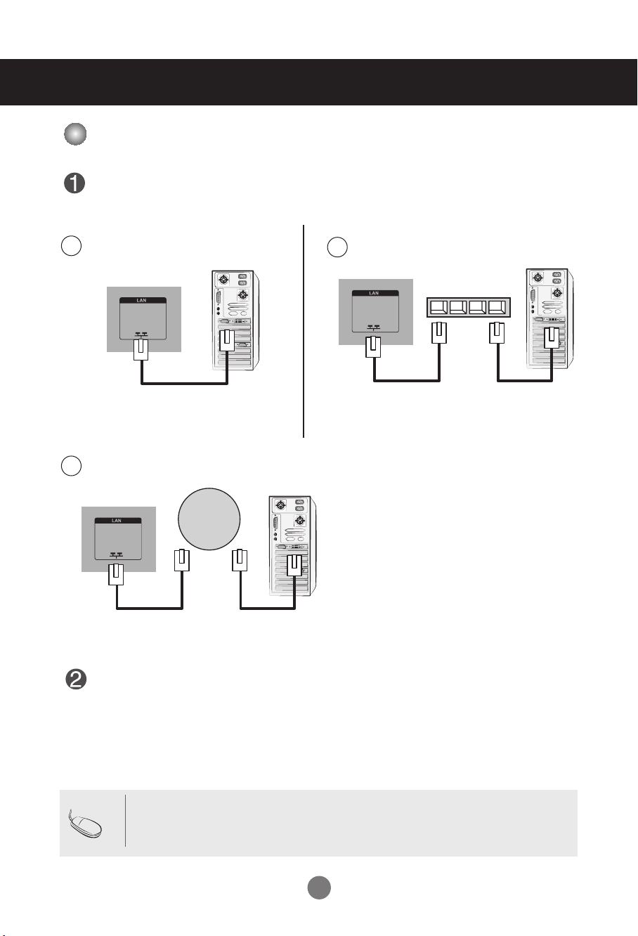
• Using LAN establishes communication between your PC and the monitor and enables to use the
OSD menus on the PC as well as on the monitor.
Note
Connect the LAN cable as shown in the below figure .
Connect the LAN cable and install the eZ-Net Manager program on the CD-ROM.
For more information about the program, please refer to eZ-Net Guide in the enclosed
CD-ROM.
Connect PC to Monitor directly.
A
Using a router(Switch)
B
Product
Using the Internet.
C
Network
PC
Product
PC
Switch
Product
PC
When using the LAN
10
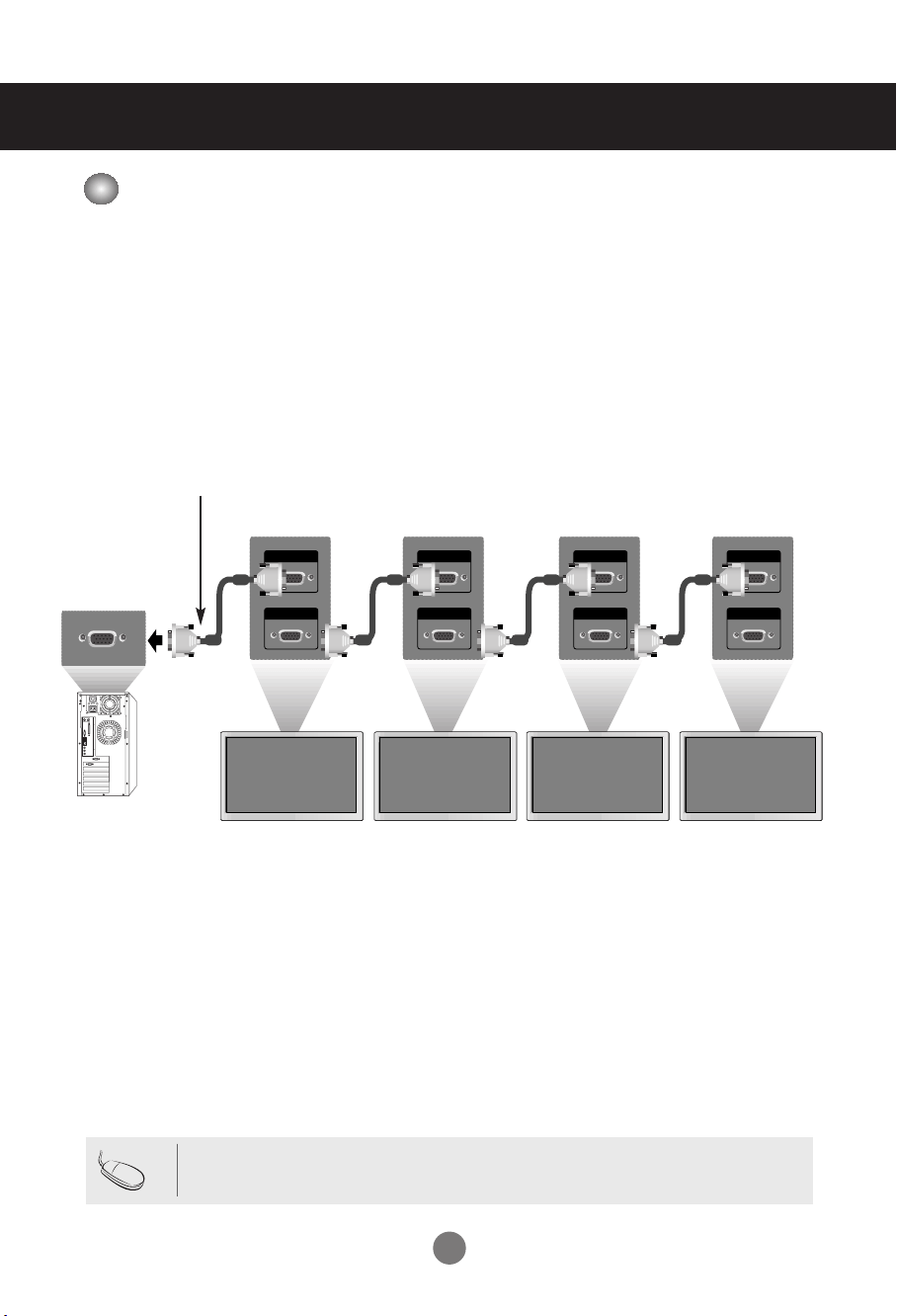
Use this function when displaying ANALOG RGB inputs of a PC to the other product.
RGB IN
RGB OUT
RGB IN
RGB OUT
RGB IN
RGB OUT
RGB IN
RGB OUT
Product 1
•
To use different products connected to each other
Connect one end of the signal input cable(15-pin D-Sub Signal Cable) to the RGB OUT
connector of product 1 and connect the other end to the RGB IN connector of other
products.
PC
Product 2
Product 3
Product 4
15-pin D-Sub Signal Cable
Connecting to External Devices
• When multi-connecting in/out cascade format, no loss cables are recommended.
We recommend that you should use cable distributor.
Note
PC
Daisy Chain Monitors
11
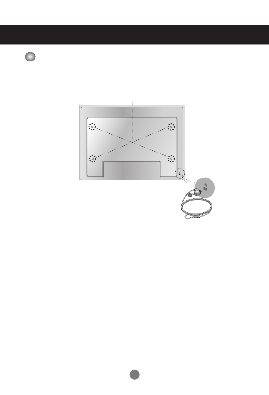
Kensington Security Slot
The Set is equipped with a kensington Security System
connector on the back panel. The cable and lock are
available separate and are not sold by LG. For more info,
visit http://www.kensington.com, the internet home page
of the Kensington company.
This product supports a VESA FDMI compliant mounting interface. These mounts are purchased
separately and not available from LG. Refer to the instructions included with wall mount for more
info.
Connecting to External Devices
VESA FDMI wall Mounting
12
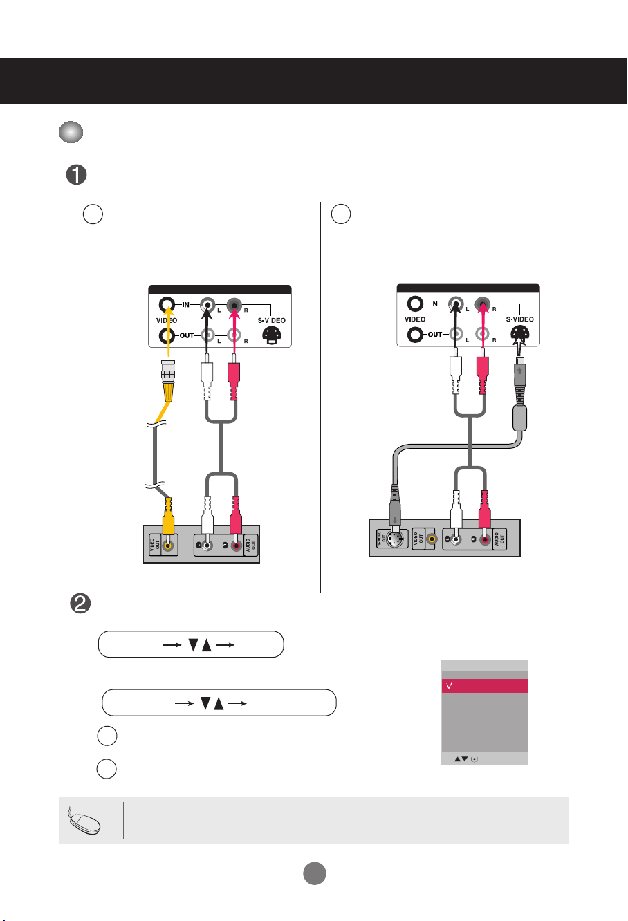
Connecting to External Devices
When connecting with an BNC cable.
•
Select AV.
When connecting with an S-Video cable.
•
Select AV.
B
A
AUDIO
AV IN/OUT
When connecting with a S-Video cable.
•
Connect to the S-Video input terminal to
watch high image quality movies.
Connect the video cable as shown in the below figure and then connect the power
cord (See page 7).
B
When connecting with a BNC cable.
•
Connect the input terminal with a
proper color match.
A
BNC Cable
(not included)
Product
VCR/DVD Receiver
Select an input signal.
Press the INPUT button on the remote control to select the input signal.
Or, press the SOURCE button on the back of the product.
INPUT SET
SOURCE
AUTO/SET
• When the BNC cable is connected simultaneously with S-Video cable, S-Video input has a priority.
Note
Audio Cable
(not included)
AUDIO
AV IN/OUT
S-Video Cable
(not included)
Audio Cable
(not included)
Product
VCR/DVD Receiver
Input
AV
Component
RGB PC
HDMI/DVI
Video Input
13
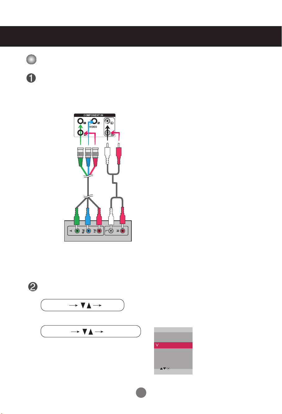
•
Select Component
AUDIO
Connect the video/audio cable as shown in the below figure and then, connect the
power cord (See page 7).
•
Connect the input terminal with a proper color match.
BNC Cable
(not included)
Product
HDTV Receiver
Select an input signal.
Press the INPUT button on the remote control to select the input signal.
Or, press the SOURCE button on the back of the product.
INPUT SET
SOURCE
AUTO/SET
Audio Cable
(not included)
Connecting to External Devices
Input
AV
Component
RGB PC
HDMI/DVI
Note
- Some devices may require HDCP in order to display HD signals.
- Component doesn't support HDCP.
Component Input (
480p/576p/720p/1080p/1080i/480i/576i)
14
AUDIO
(RGB/DVI)
REMOTE
CONTROL IN
RGB IN
RGB OUT
HDMI/DVI IN
RGB IN
RGB OUT
HDMI/DVI IN
AUDIO
(RGB/DVI)
REMOTE
CONTROL IN
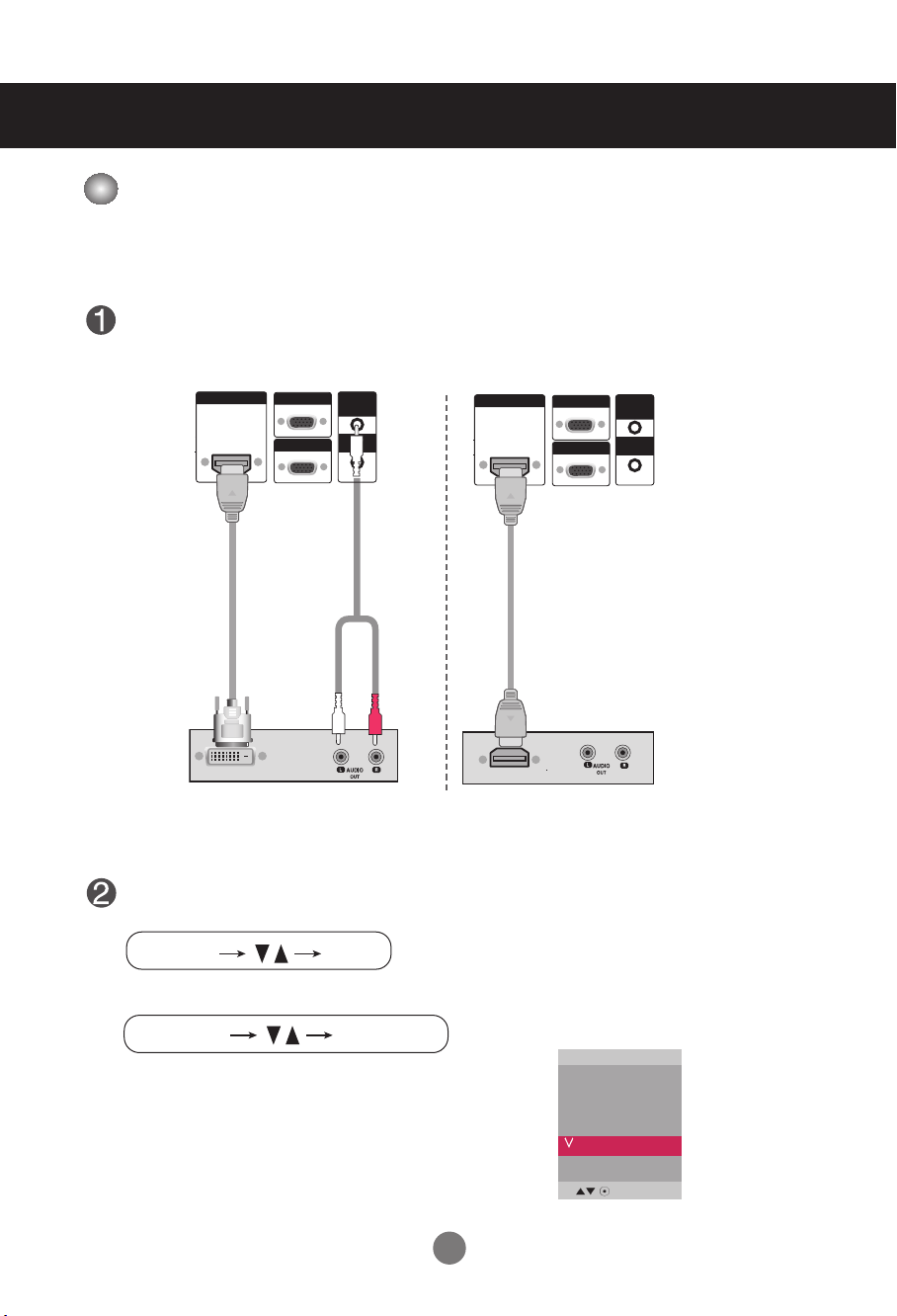
Connect the video/audio cable as shown in the below figure and then connect the
power cord (See page 7).
RCA-PC
Audio Cable
Product
VCR/DVD/Set-top Box
HDMI to DVI
Signal Cable
(not included)
VCR/DVD/Set-top Box
Product
Select an input signal.
Press the INPUT button on the remote control to select the input signal.
Or, press the SOURCE button on the back of the product.
INPUT SET
SOURCE
AUTO/SET
HDMI Signal Cable
(not included)
Connecting to External Devices
When connecting with a HDMI to DVI signal input cable.
When connecting with a HDMI signal input cable.
• Select HDMI/DVI
Input
AV
Component
RGB PC
HDMI/DVI
-HDMI Supports High Definition input and HDCP (High-bandwidth Digital Content
Protection). Some devices require HDCP in order to display HD signals.
Note : Dolby Digital is not supported.
HDMI Input (480p/576p/720p/1080i/1080p)
15
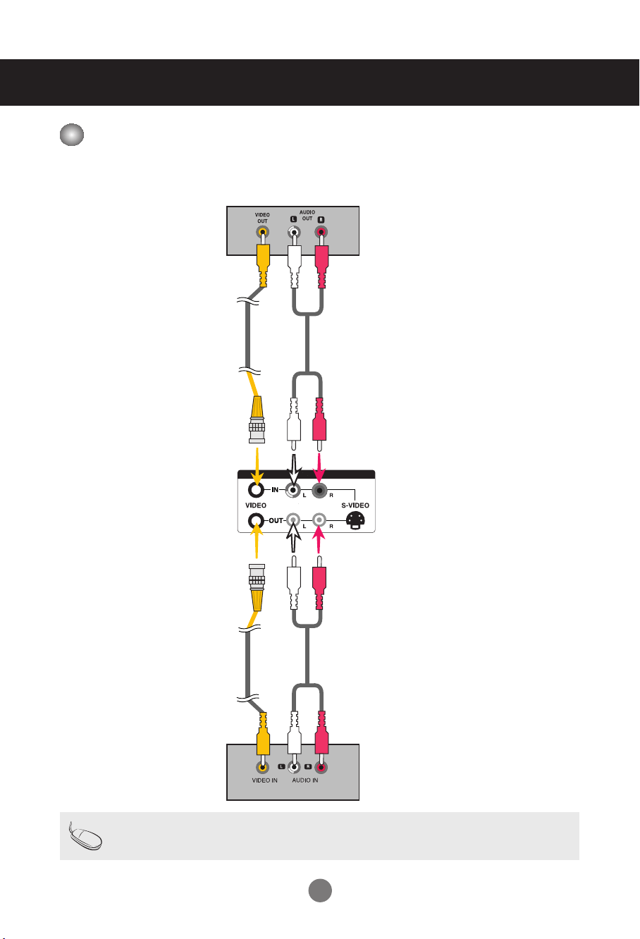
- When using AV input, you can connect the AV Out to other monitors.
AUDIO
AV IN/OUT
Video/TV
BNC Cable
(not included)
Audio Cable
(not included)
BNC Cable
(not included)
Audio Cable
(not included)
Video/TV
Product
Connecting to External Devices
• When multi-connecting in/out cascade format, no loss cables are recommended.
We recommend that you should use cable distributor.
Note
Watching
AV Outputs
16
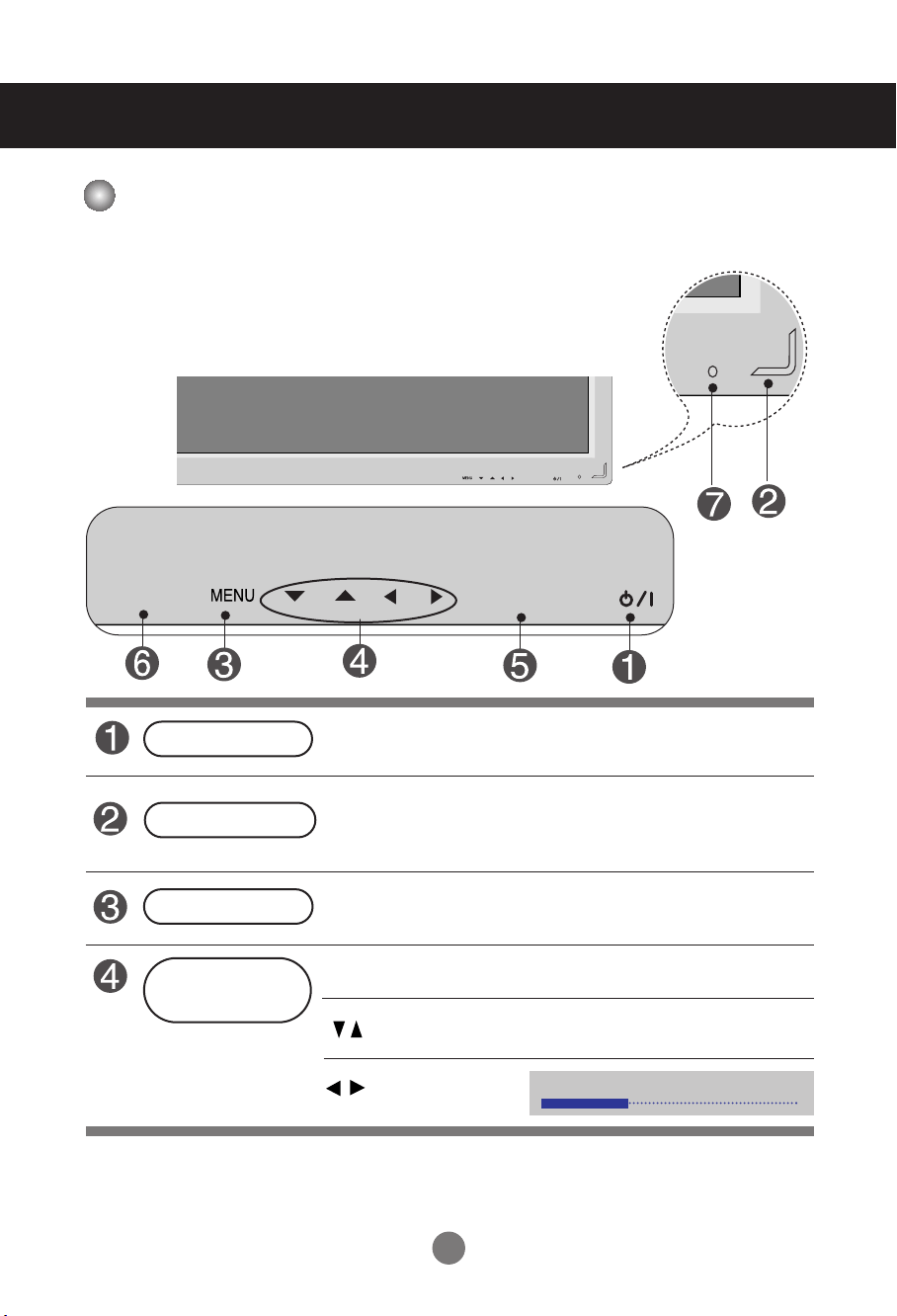
User Menus
• Press this button to turn on the power. Press this button again to
turn it off.
• This Indicator lights up blue when the display operates normally(on
mode). If the display is in sleep (Energy Saving) mode, this indicator
color changes to amber.
Power Button
• Adjust the volume.
• Adjust the up and down.
• Use this button to show/hide the OSD (On Screen Display) menu
screen.
MENU Button
• Use
this
button to select an icon or adjust the setting in the OSD screen.
OSD Select /
Adjust Button
Power Indicator
Volume
35
AUTO/SET
SOURCE
AUTO/SET
SOURCE
Screen Adjustment options
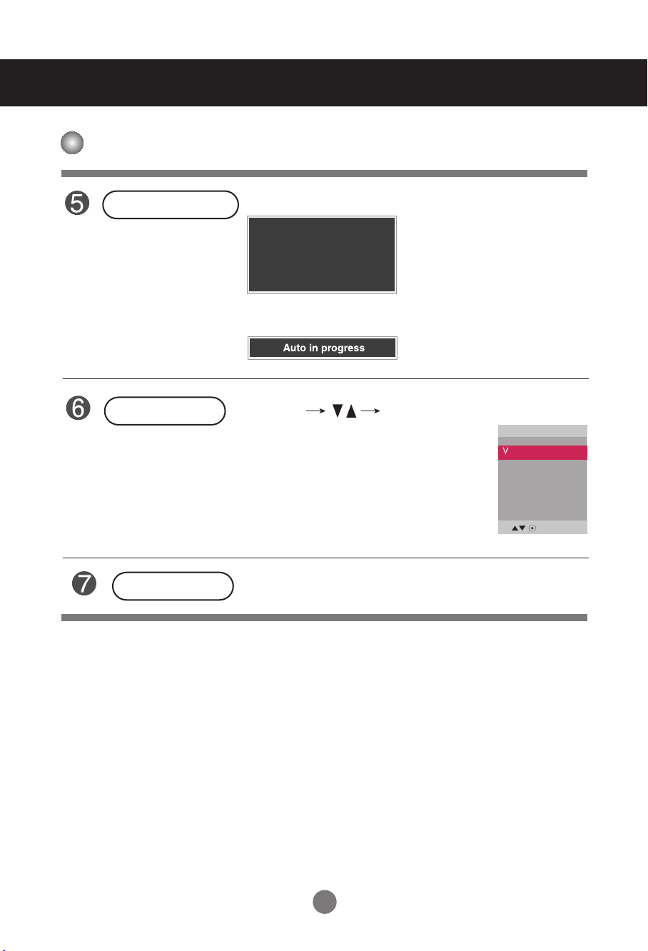
17
• This is where the unit receives signals from the remote control.
Screen Adjustment options
[For PC Analog signal]
AUTO/SET Button
AV Composite Video, Separate Video
Component HDTV, DVD
RGB PC 15-pin D-Sub analog signal
HDMI/DVI Digital signal
- Toggles between inputs
SOURCE Button
SOURCE
AUTO/SET
Auto in progress
For opimal display change
resolution to 1920 x 1080
IR Receiver
User Menus
[When 1920 x 1080 is selected]
Input
AV
Component
RGB PC
HDMI/DVI
18
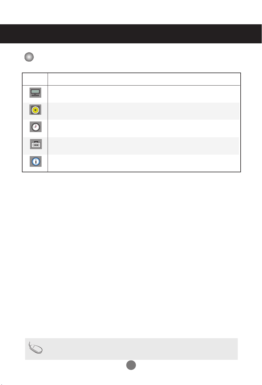
User Menus
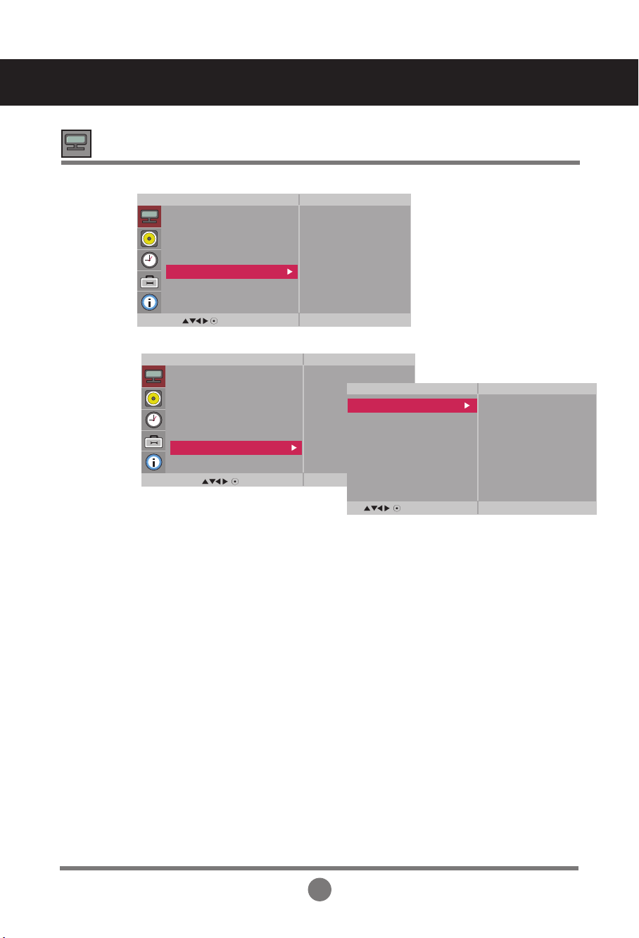
OSD Menu
Icon Function Description
Picture
Audio
Adjusts the audio options.
Adjusts screen brightness, contrast and color that you prefer.
Note
OSD(On Screen Display)
The OSD function enables you to adjust the screen status conveniently since it provides graphical
presentation.
Option
Adjusts the screen status according to the circumstances.
Time
Adjusts the timer options.
Information
Adjust Set ID and check Serial No. and SW version and IP
address
19
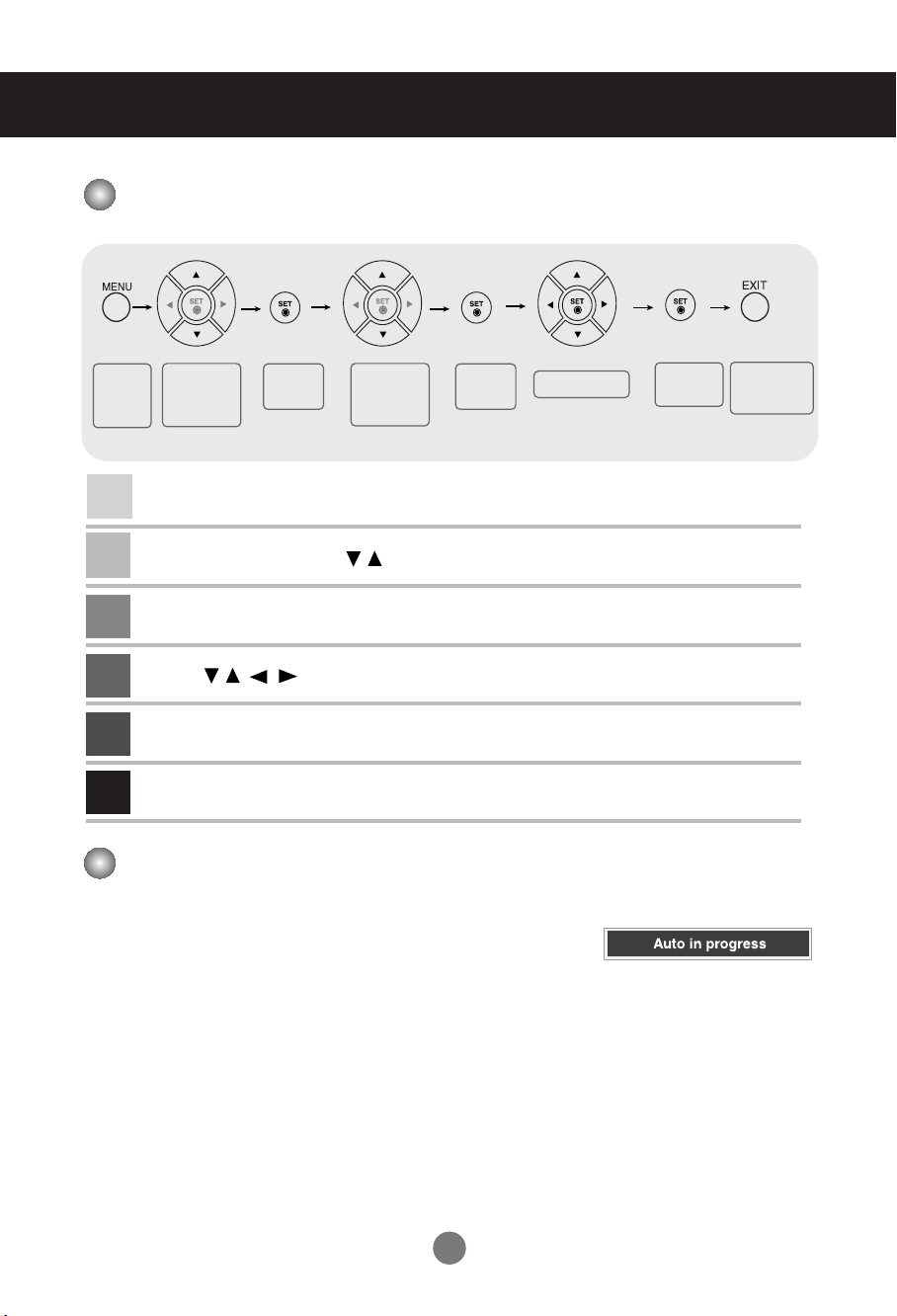
How to adjust the OSD (On Screen Display) screen
•
Use the remote control to adjust the OSD screen.
How to adjust the screen automatically
Press the AUTO/SET button (AUTO button on a remote Control) in the
PC analog signal. Then optimal screen settings will be selected that fit
into the current mode. If adjustment is not satisfactory, you can adjust
the screen manually.
Press the MENU Button, then the main menu of the OSD appears.
To access a control, use the Buttons.
When the icon you want becomes highlighted, press the SET Button.
Use the Buttons to adjust the item to the desired level.
Accept the changes by pressing the SET Button.
Exit the OSD by pressing the EXIT Button.
1
2
3
4
5
6
Pops up
the menu
screen
Move where
you want to
adjust
Move where
you want to
adjust
Select a
menu icon
Select a
menu icon
Adjust the status
Save
adjustment
Exit from the
menu screen.
User Menus
[When 1920 x 1080 is selected]
20
User Menus
Adjusting Screen Color
Backlight : To control the brightness of the screen,adjust the brightness of LCD panel.
Contrast : Adjust the difference between the light and dark levels in the picture.
Brightness : To adjust the brightness of the screen.
Color : To adjust the color to desired level.
Sharpness : To adjust the clearness of the screen.
Tint :To adjust the tint to desired level.
Expert : To compensate for each image mode, or adjust image values according to a
particular image. (Applied only to User2 menu.)
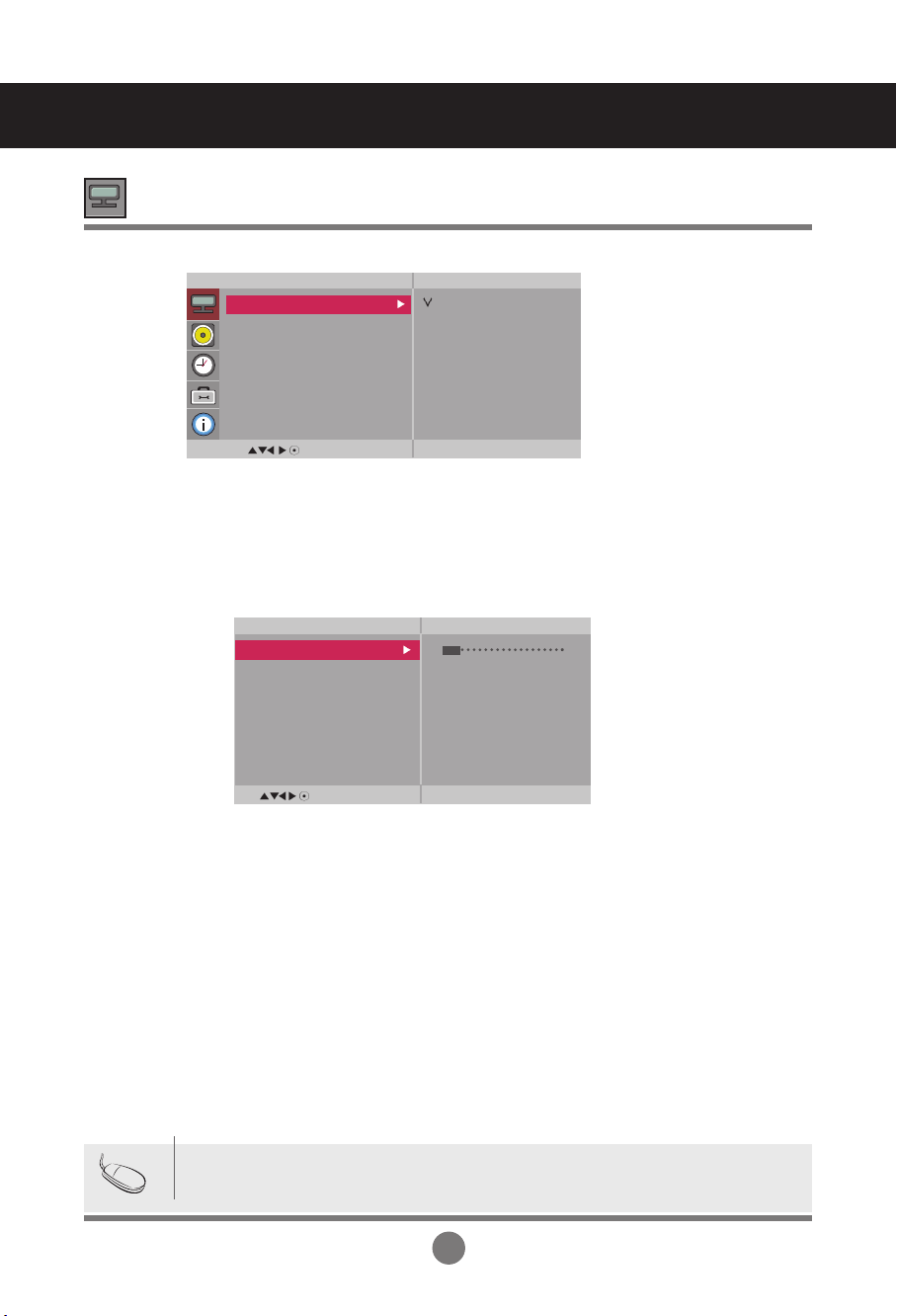
Toggles between screen presets.
• Vivid : Select this option to display with a sharp image.
• Standard : The most general and natural screen display status.
• Cinema : Select this option to lower brightness by one level.
• Sport : Select this option to display with a soft image.
• Game : To enjoy dynamic image when playing a game.
• User1,2 : Select this option to use the user-defined settings.
Picture
Mode
Note
If the '
Picture Mode
' setting in the Picture menu is set to Vivid, Standard, Cinema,
Sport or Game the subsequent menus will be automatically set.
MENU
Picture
Picture Mode
Color Temperature
Advanced
Aspect Ratio
Picture Reset
Screen
Vivid
Standard
Cinema
Sport
Game
User1
User2
MENU
User2
Backlight 20
Contrast 90
Brightness 50
Color 50
Sharpness 50
Tint 50
Expert
21
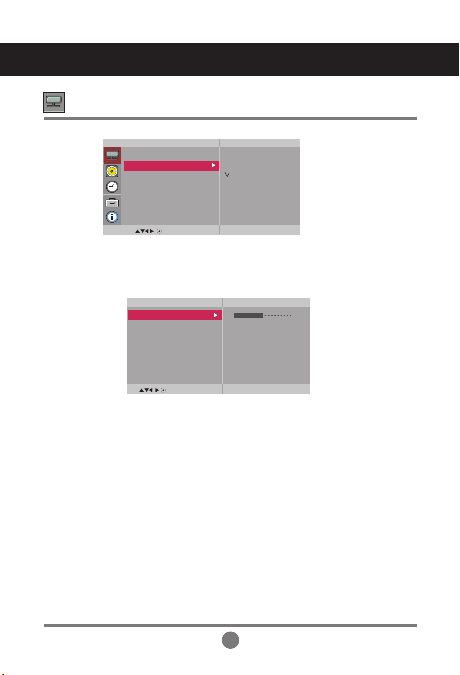
Red / Green / Blue
Set your own color levels.
Color Settings
• Cool : Slightly purplish white.
• Medium : Slightly bluish white.
• Warm : Slightly reddish white.
• User : Select this option to use the user-defined settings.
Color
Temperature
MENU
Picture
Picture Mode
Color Temperature
Advanced
Aspect Ratio
Picture Reset
Screen
Cool
Medium
Warm
User
User Menus
Adjusting Screen Color
MENU
User
Red 0
Green 0
Blue 0
22
User Menus
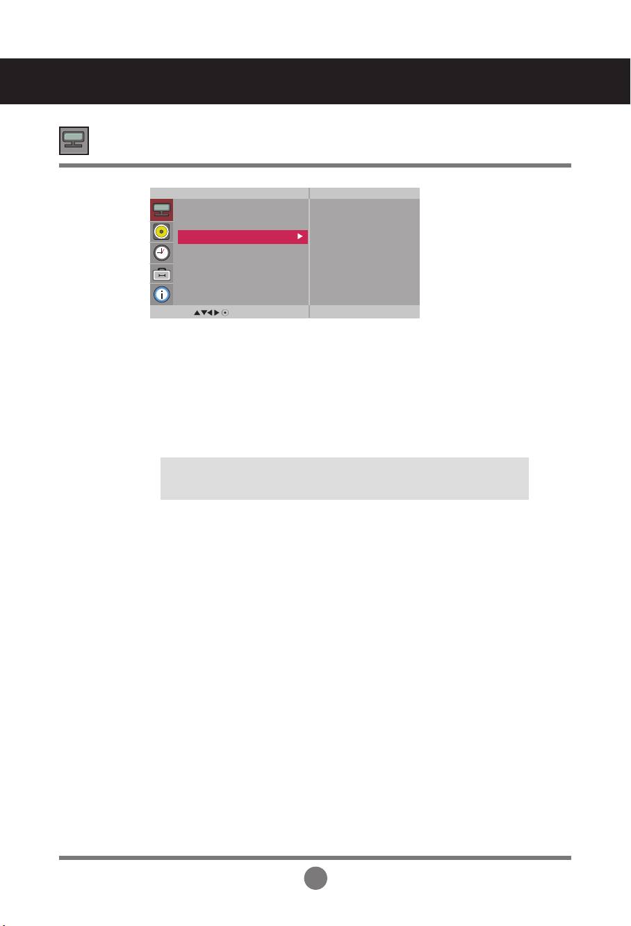
• NR : Removing the noise up to the point where it does not damage the
original picture.
• Gamma : Set your own gamma value. : -50/0/50
On the monitor, high gamma values display whitish images and low gamma
values display high contrast images.
• Film Mode : (
Function works in the following mode - AV, Component 480i/576i)
When you watch a movie, this function adjusts the set to the best picture
appearance.
• Black Level : (
Function works in the following mode - AV(NTSC), HDMI/DVI
adjusts the contrast and the brightness of the screen using the
black level of the screen.
Advanced
• Low : The reflection of the screen gets brighter.
• High : The reflection of the screen gets darker.
MENU
Picture
Picture Mode
Color Temperature
Advanced
Aspect Ratio
Picture Reset
Screen
To set
Adjusting Screen Color
23
User Menus
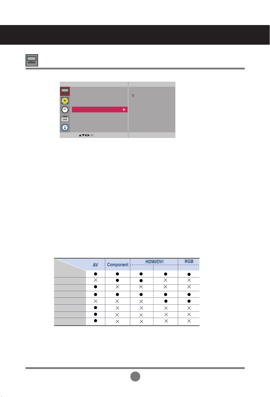
To select the image size of the screen.
Aspect Ratio
The aspect ratio is not adjusted from the original. It is set by the program
being watched.
Original
This picture format is 4:3 aspect ratio.
4:3
Widescreen mode.
16:9
14:9 programs are viewed normally in 14:9 with black bars added to the
top and bottom. 4:3 programs are magnified on the top/bottom and
left/right sides.
14:9
4:3 programs are magnified until they fill the 16:9 screen. The top and
bottom will be cut off.
Zoom1, 2
Adjusting Screen Color
MENU
Picture
Picture Mode
Color Temperature
Advanced
Aspect Ratio
Picture Reset
Screen
16:9
Original
4:3
14:9
Zoom1
Zoom2
Allows you to enjoy the transmitted data fully without any images cut off.
(* This menu is activated only in 720p, 1080p and 1080i in Component mode.)
Just Scan
The aspect ratio is not adjusted from the original. Used in PC mode.
(Only HDMI/ DVI PC, RGB PC)
1:1
<AV>
PCPC
DTV
Original
4:3
1:1
16:9
14:9
Zoom1
Zoom2
MODE
ARC
Just Scan
24
MENU
Picture
Picture Mode
Color Temperature
Advanced
Aspect Ratio
Picture Reset
Screen
To set
User Menus
Adjusting Screen Color
Return Picture Mode,
Color Temperature
, Advanced to the default factory settings.
Picture Reset
MENU
Picture
Picture Mode
Color Temperature
Advanced
Aspect Ratio
Picture Reset
Screen
To set
Auto Config.
(RGB PC input only) : This button is for the automatic adjustment of the
screen position, clock and phase. This function is available for analog signals only.
Manual Config. :
If the picture isn't clear after auto adjustment and characters are still
trembling, adjust the picture phase manually.
* Phase, Clock function are not available in Component, HDMI/DVI DTV.)
Clock :
To minimize any vertical bars or stripes visible on the screen background. The
horizontal screen size will also change. This function is available for analog signals only.
Phase :
To adjust the focus of the display. This item allows you to remove any horizontal
noise and clear or sharpen the image of characters. This function is available for analog
signals only.
H-Position :
Moving the screen position horizontally.
V-Position :
Moving the screen position vertically.
XGA Mode
(RGB-PC only). : For more improved or better picture quality, select the same
mode corresponding to computer resolution.
Reset: Return
Manual config.
to the default factory settings.
Screen
MENU
Screen
Auto Config.
Manual Config.
XGA Mode
Reset
To set
Adjust the screen video.
H-Size : Adjust the horizontal size of the screen.
V-Size : Adjust the vertical size of the screen.
25
User Menus
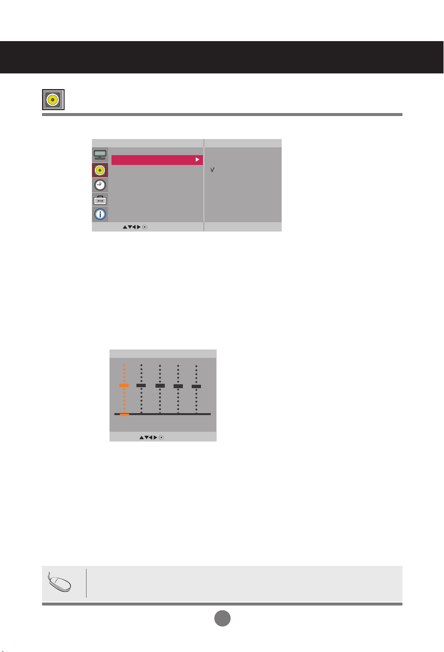
The best sound tone quality will be selected automatically depending on the video type that you're currently watching.
Sound
Mode
Adjusting the audio function
Note
When connected to your computer and the '
Sound
Mode
' setting in the audio menu is
Clear Voice, Standard
, Music,
Cinema
or Sport, the
available menus are Balance, Auto Volume, Speaker.
To adjust uneven sound volumes across all channels or signals automatically to the most
appropriate level. To use this feature, select On.
Use this function to balance sound from the left and right speakers.
You can adjust internal speaker status.
If you want to use your external hi-fi stereo system, turn off the internal speakers of the set.
Auto
Volume
Balance
Speaker
• Clear Voice : By differentiating the human sound range from others,it helps users listen to human
voices better.
• Standard : The most commanding and natural audio.
• Music : Select this option to enjoy the original sound when listening to the music.
• Cinema : Select this option to enjoy sublime sound.
• Sport : Select this option to watch sports broadcasting.
• Game : To enjoy dynamic sound when playing a game.
• User : Select this option to use the user-defined audio settings.
MENU
Audio
Sound Mode
Auto Volume
Balance
Speaker
Clear Voice
Standard
Music
Cinema
Sport
Game
User
MENU
User
0.1 0.5 1.5 5.0 10
KHz
26
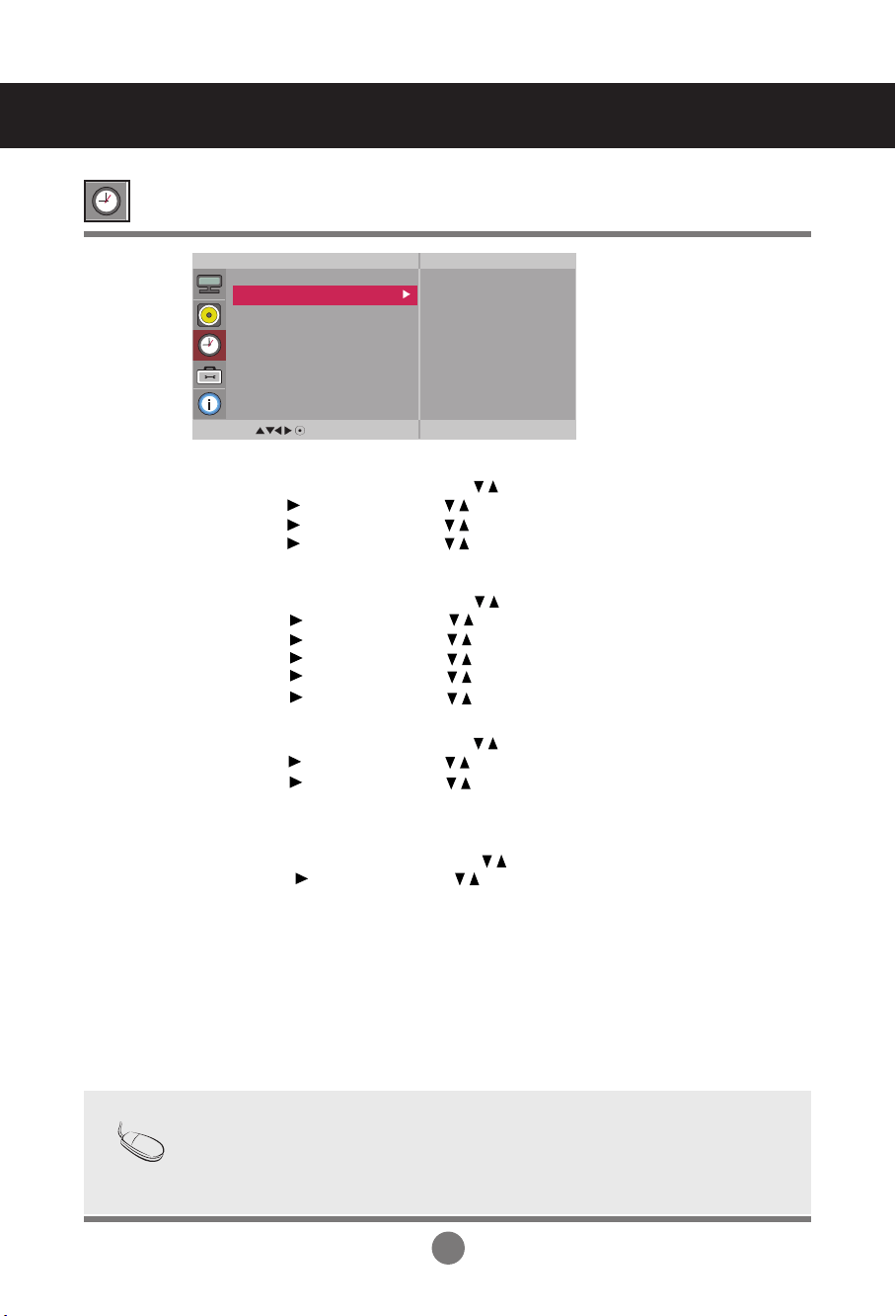
Clock
Adjusting the timer function
• In the event of power interruption (disconnection or power failure), the clock must be reset.
• Once the on or off time is set, these functions operate daily at the preset time.
• Off time function overrides On time function if they are set to the same time.
• When On time is operated, input screen is turned on as it was turned off.
Note
If the current time is incorrect, reset the clock manually.
1) Press the MENU button and then use
button to select the Time menu.
2) Press the button and then use
button to select the Clock menu.
3) Press the button and then use
button to set the hour(00~23).
4) Press the button and then use
button to set the minutes(00~59).
On/Off Timer
The off time automatically switches the set to standby at the pre-set time.
1) Press the MENU button and then use
button to select the Time menu.
2) Press the button and then use
button to select
On/Off Timer
.
3) Press the button and then use
button to set the hour(00~23).
4) Press the button and then use
button to set the minutes(00~59).
5) Press the button and then use
button to select On or Off.
6) Press the button and then use
button to select Select input or On Timer
Sleep Time
The power is automatically turned off when the time set by a user is passed.
1) Press the MENU button and then use
button to select the
Sleep Time
menu.
2
) Press the button and then use
button to set the hour(00~23).
3) Press the button and then use
button to set the minutes(00~59).
User Menus
Power On
Delay
When connecting multiple monitors and turning the power on, the monitors are
turned on individually to prevent overload.
MENU
Time
Clock
On/Off Timer
Sleep Time
Auto Sleep
Power On Delay
Power Saving
_ _ : _ _ AM
Auto Sleep
If Auto Sleep is active and there is no input signal, the set switches to off mode
automatically after 10 minutes.
1) Press the MENU button and then use
button to select the
Auto
Sleep menu.
2) Press the button and then use
button to select On or Off.
27
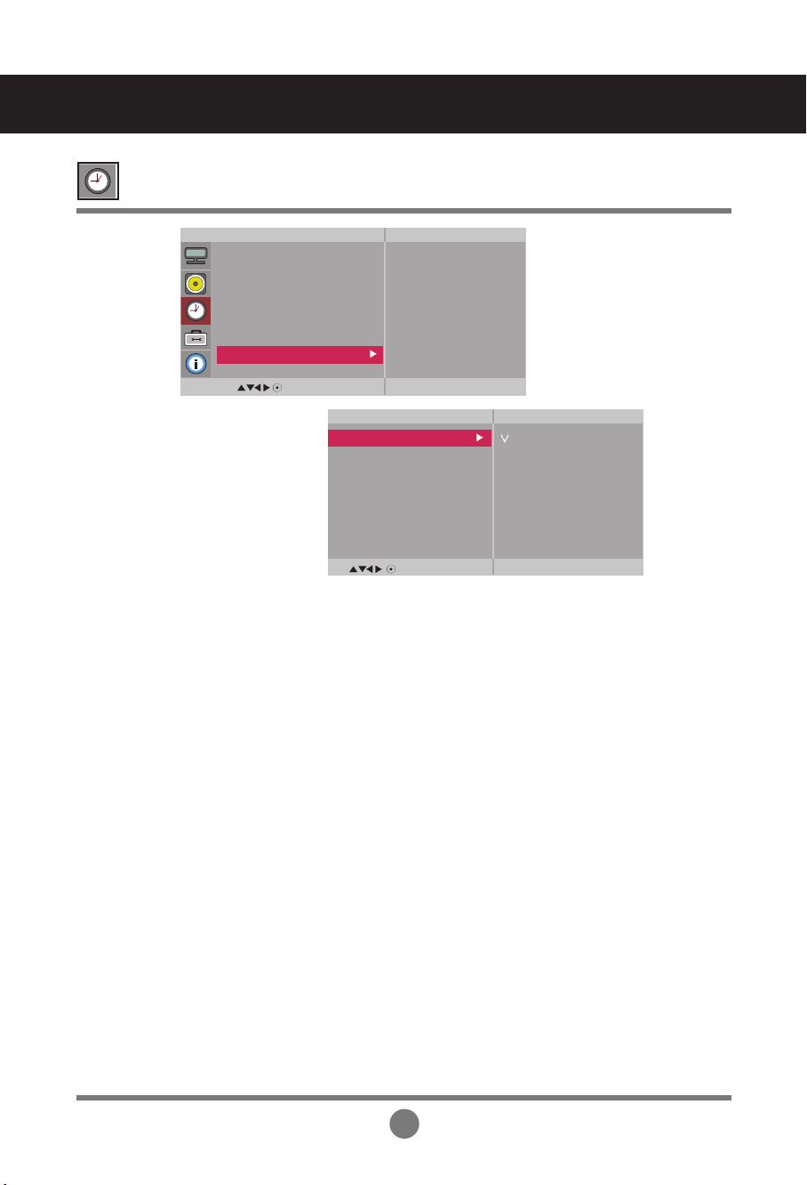
User Menus
Power
Saving
This screen brightness adjusting menu helps you save energy.
Adjusting the timer function
MENU
Time
Clock
On/Off Timer
Sleep Time
Auto Sleep
Power On Delay
Power Saving
To set
• Level: Total 4 screen brightness levels are provided.
- Off: 100% light
- Level 1: 80% light
- Level 2: 60% light
- Level 3: 40% light
• On Time : Enables to automatically turn on the Power Saving option at a scheduled time.
• Off Time : Enables to automatically turn off the Power Saving option at a scheduled time.
*The Power Saving option becomes in effect only during the scheduled time frame.
The On Time and Off Time menus become disabled if Level Off is selected.
MENU
Power Saving
Level
On Time
Off Time
Off
Level 1
Level 2
Level 3
28
User Menus
Selecting the options
Language
To choose the language in which the control names are displayed.
Use the buttons to select On or Off. The monitor can be set up so that it can only be
used with the remote control. This feature can prevent unauthorized viewing.
In order to lock the OSD screen adjustment, set the
Key Lock
tab to the 'On' position.
In order to unlock it, do the following :
•
Push the MENU button on the remote control and set
Key Lock
to the 'Off' position.
Key Lock
ISM Method
Normal :
Leave on normal if you don't foresee image burn in being a problem.
White wash :
White wash fills the screen with solid white. This helps removes permanent
images burned into the screen. A permanent image may be impossible to
clear entirely with white wash.
Orbiter : May help prevent ghost images. However, it is best not to allow any fixed image to
remain on the screen. To avoid a permanent image on the screen, the screen will
move every 2 minutes.
Inversion : This function inverts the panel color of the screen. The panel color is automatically
inverted every 30 minutes.
A frozen or still picture from a PC/Video game displayed on the screen for prolonged periods could
result in a ghost image remaining even when you change the image. Avoid allowing a fixed image
to remain on the screen for a long period of time.
MENU
Option
Language
Key Lock
ISM Method
Power Indicator
DPM Select
Tile Mode
Network Setup
Factory Reset
To set
Power Indicator
Use this function to set the power indicator on the front side of the product to
On or Off.
DPM Select A user can choose to turn the power saving mode on / off.
Dot Wash : This function moves the black dots of the screen. The black dots is automatically
moved every 5 second.
29
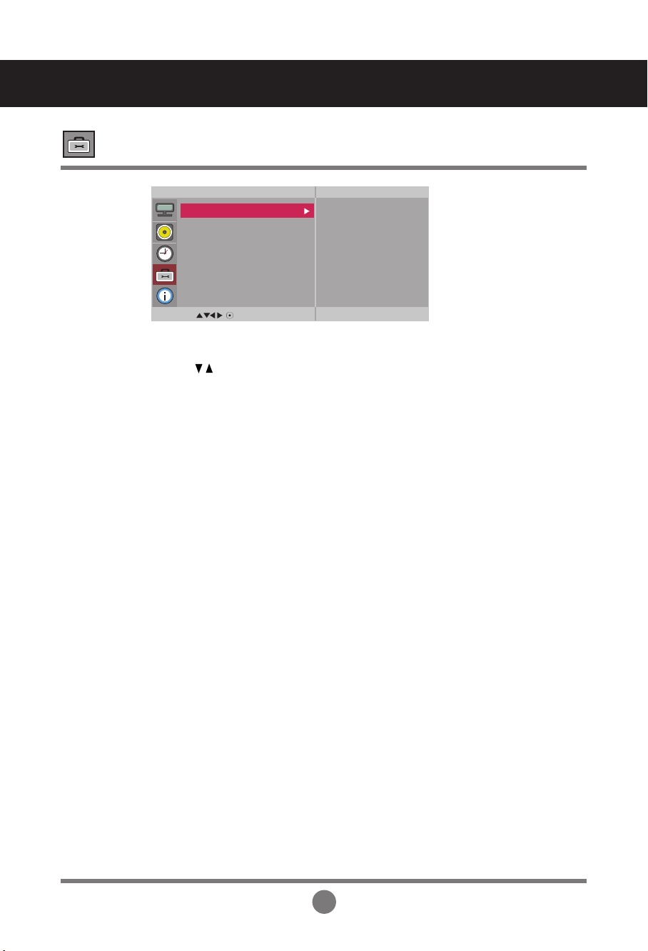
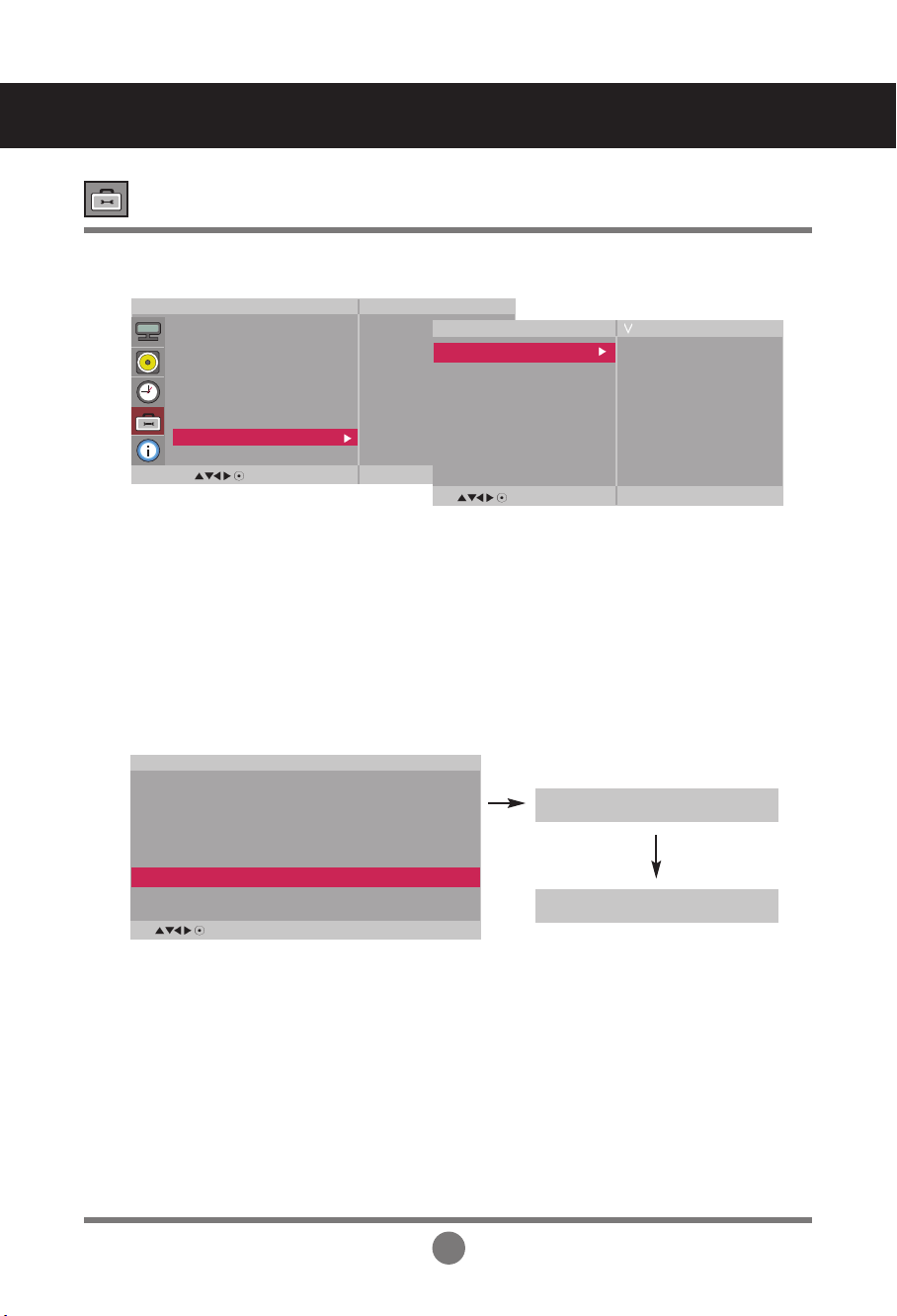
Tile mode
Tile mode and choose Tile alignment and set the ID of the current product to set
location.
* Only after pressing the SET button the
adjustments made to the settings will be saved.
It is used to enlarge the screen and
also used with several products to
view screen.
• To use this function
- Must be displayed with various other products.
- Must be in a function that can be connected to RS-232C or RGB Out
• Tile Mode
-
Tile mode : column x row ( c = 1, 2, 3, 4,5 r = 1, 2, 3, 4,5)
- 5 x 5 available.
- Configuration of an integration screen is also available as well as configuration of
One by one Display.
ID 1
ID 2
ID 3
ID 4
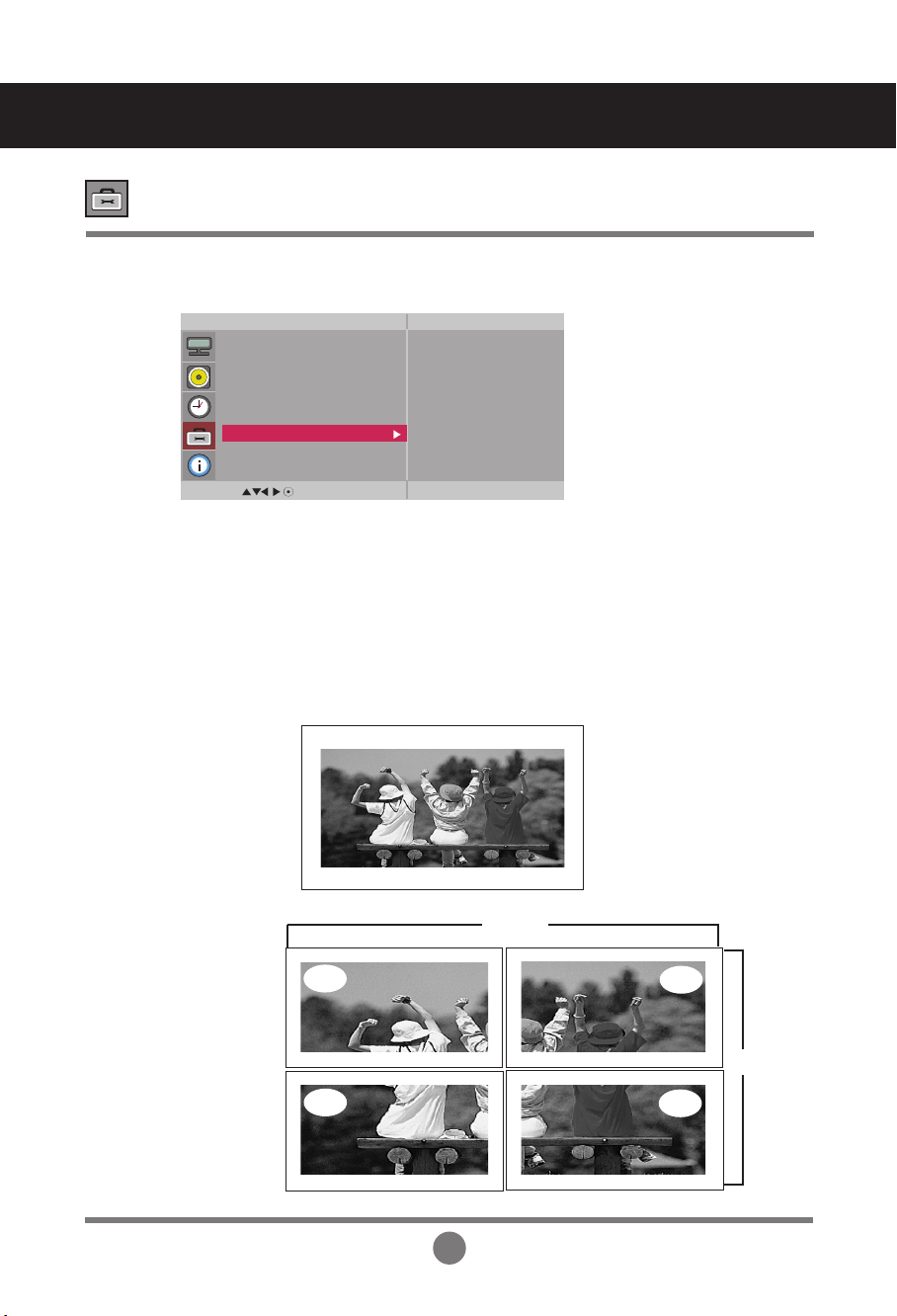
-
Tile mode (product 1 ~ 4) : c(2) x r(2)
column
row
User Menus
Selecting the options
MENU
Option
Language
Key Lock
ISM Method
Power Indicator
DPM Select
Tile Mode
Network Setup
Factory Reset
Tile Mode Off
H-Size 0
V-Size 0
H-Position < >
V-Position < >
Reset
Tile ID 1
Natural Off
30
User Menus
ID 1
ID 2
column
row
-
Tile mode (product 1 ~ 2) : c(2) x r(1)
row
column
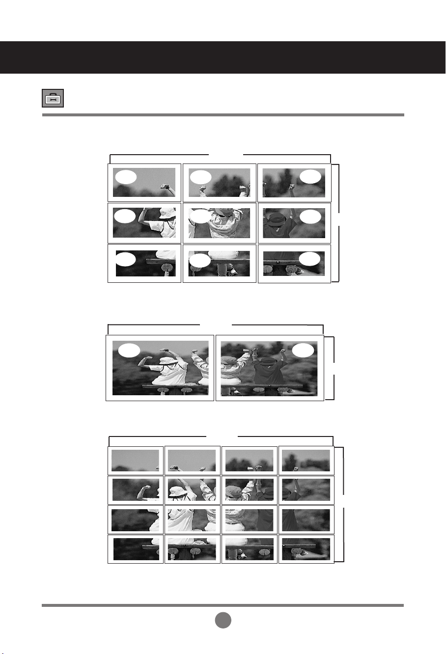
-
Tile mode (product 1 ~ 9) : c(3) x r(3)
ID 1
ID 2
ID 3
ID 4
ID 5
ID 6
ID 7
ID 8
ID 9
row
column
-
Tile mode (product 1 ~16) : c(4) x r(4)
ID 1
ID 5
ID 9
ID 13
ID 2
ID 6
ID10
ID 14
ID 3
ID 7
ID 11
ID 15
ID 4
ID 8
ID 12
ID 16
Selecting the options
31
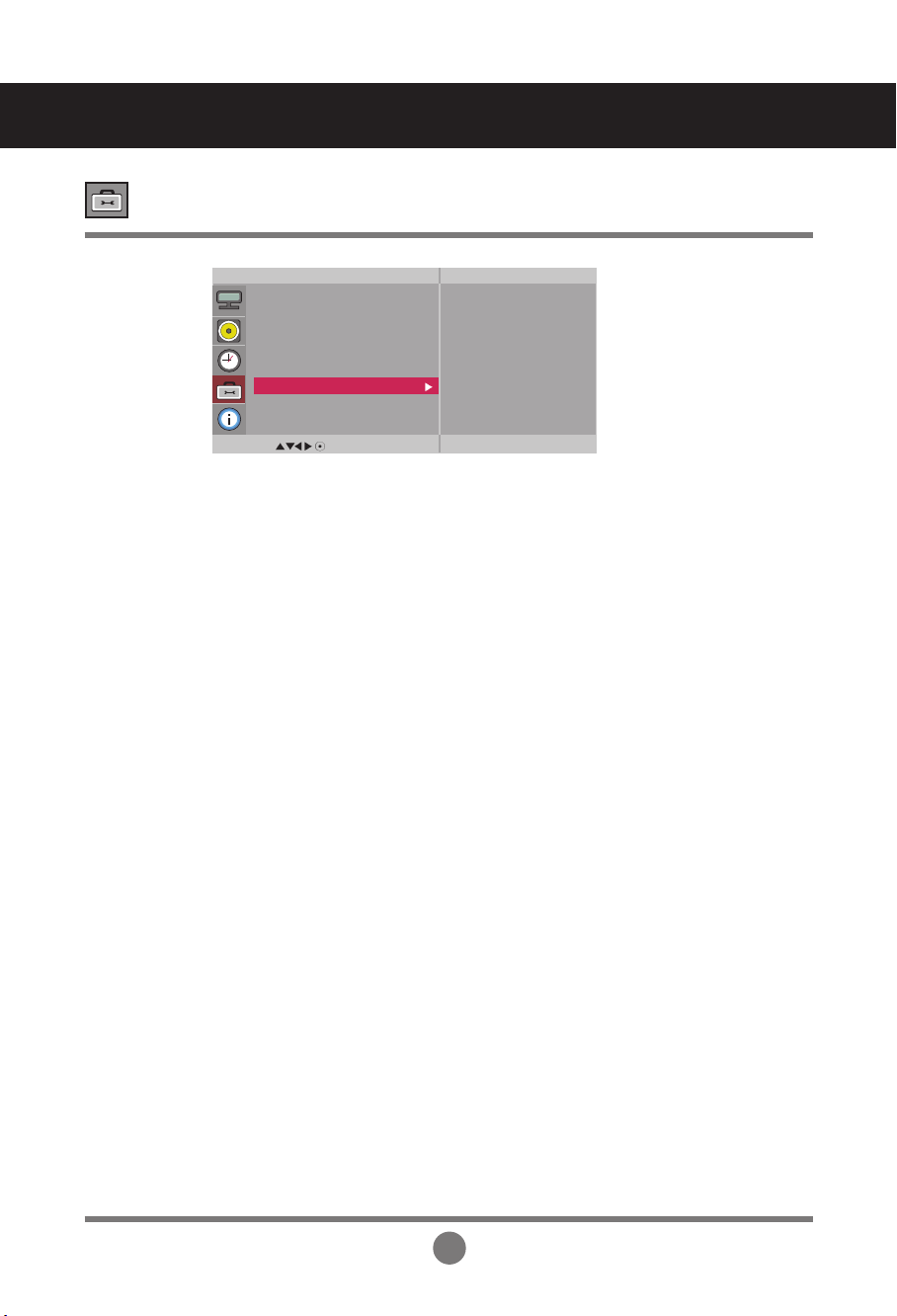
Adjust the horizontal size of the screen taking into account the size of the bezel.
Adjust the vertical size of the screen taking into account the size of the bezel.
• H-Size
• V-Size
• Reset
Select the location of the Tile by setting an ID.
• Tile ID
Function to initialize and release Tile.
All Tile setting are released when selecting Tile recall and the screen returns to
Full screen.
•
H-Position
Moving the screen position vertically.
•
V-Position
Moving the screen position horizontally.
User Menus
Selecting the options
MENU
Option
Language
Key Lock
ISM Method
Power Indicator
DPM Select
Tile Mode
Network Setup
Factory Reset
Tile Mode Off
H-Size 0
V-Size 0
H-Position < >
V-Position < >
Reset
Tile ID 1
Natural Off
The image is omitted by the distance between the screens to be naturally shown.
• Natural
Tile mode
32
User Menus
Sets up network connections.
-LAN : Enables communication via Ethernet.
- RS-232C : Enables communication via Serial.
• Network Select
Allocates and sets up IP automatically.
• DHCP
Sets up IP address, Gateway, Subnet Mask, Primary DNS and Secondary DNS.
The setup process is complete when you select Execute, and "IP Setup Completed" is
displayed at the bottom of the screen. While "Wait for IP Setup" is displayed, you cannot
use the local keys and remote control. "Wait for IP Setup" is displayed for up to 40
seconds.
• Manual
MENU
Option
Language
Key Lock
ISM Method
Power Indicator
DPM Select
Tile Mode
Network Setup
Factory Reset
To set
Factory Reset Select this option to return to the default factory settings.
Network Setup
Sets up network information.
MENU
Network Setup
Network Select
DHCP
Manual
LAN
RS-232C
MENU
Manual
IP Address
Subnet Mask
Default Gateway
Primary DNS
Secondary DNS
Execute
000 . 000 . 000 . 000
000 . 000 . 000 . 000
000 . 000 . 000 . 000
000 . 000 . 000 . 000
000 . 000 . 000 . 000
*If Network Select is set to Serial, DHCP and Manual are disabled.
Selecting the options
Wait for IP Setup
IP Setup Completed
33
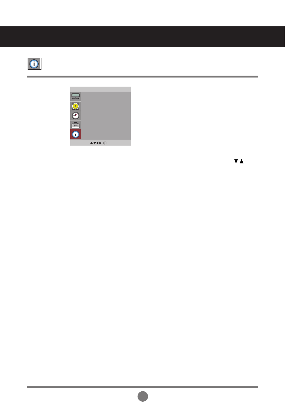
User Menus
Adjust Set ID and check Serial No. and SW version.
MENU
Information
Set ID
Serial No.
SW Version
IP Address
You can assign a unique Set ID NO (name assignment) to each product when several
products are connected for display. Specify the number (01H~63H) using the
button and exit. Use the assigned Set ID to individually control each product using the
Product Control Program.
Set ID
This menu shows the serial number of the product.
Serial No.
This menu shows the software version.
SW Version
Displays a selected network's IP address.
IP Address
34
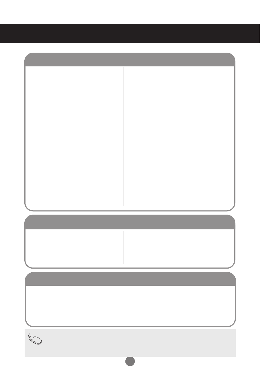
• See if the power cord is properly connected to the
outlet.
• See if the power switch is turned on.
• May need service.
• Adjust brightness and contrast again.
• Backlight may need repair.
• If the product is in power saving mode, move the
mouse or press any key.
• Turn both devices off and then back on.
• The signal from the PC (video card) is out of the
vertical or horizontal frequency range of the
product. Adjust the frequency range by referring
to the Specifications in this manual.
* Maximum resolution
RGB : 1920 x 1080 @ 60 Hz
HDMI/DVI : 1920 x 1080 @60 Hz
• The signal cable between PC and product is not
connected. Check the signal cable.
• Press the 'INPUT' menu in the remote Control to
check the input signal.
No image is displayed
Troubleshooting
• The control locking function prevents unintentional
OSD setting change due to careless usage. To unlock
the controls, simultaneously press the Menu button
and button for several seconds. (You cannot set this
function using the remote control buttons. You can set
this function in the product only.)
●
The 'Key Lock On' message
appears when pressing the Menu
button.
' Key Lock On' message appears.
• Install the product driver, which is provided with
the product, or download it from the web site.
(http://www.lge.com)
• See if the plug&play function is supported by
referring to the video card user manual.
●
Did you install the driver?
'Unknown Product' message appears when the product is connected.
Note
* Vertical frequency: To enable the user to watch the product display, screen image should be changed tens of times
every second like a fluorescent lamp. The vertical frequency or refresh rate is the times of image display per second.
The unit is Hz.
* Horizontal frequency: The horizontal interval is the time to display one vertical line. When 1 is divided by the
horizontal interval, the number of horizontal lines displayed every second can be tabulated as the horizontal
frequency. The unit is kHz.
▲
●
Is the product power cord connected?
●
Is the power indicator light on?
●
Power is on, power
indicator
is blue but
the screen appears extremely dark.
●
the power indicator amber?
●
Does the 'Out of range' message
appear?
●
Does the 'Check signal cable' message
appear?
35
●
Is the screen position wrong?
●
Do thin lines appear on the
background screen?
●
Horizontal noise appears or the
characters look blurred.
●
The screen is displayed abnormally.
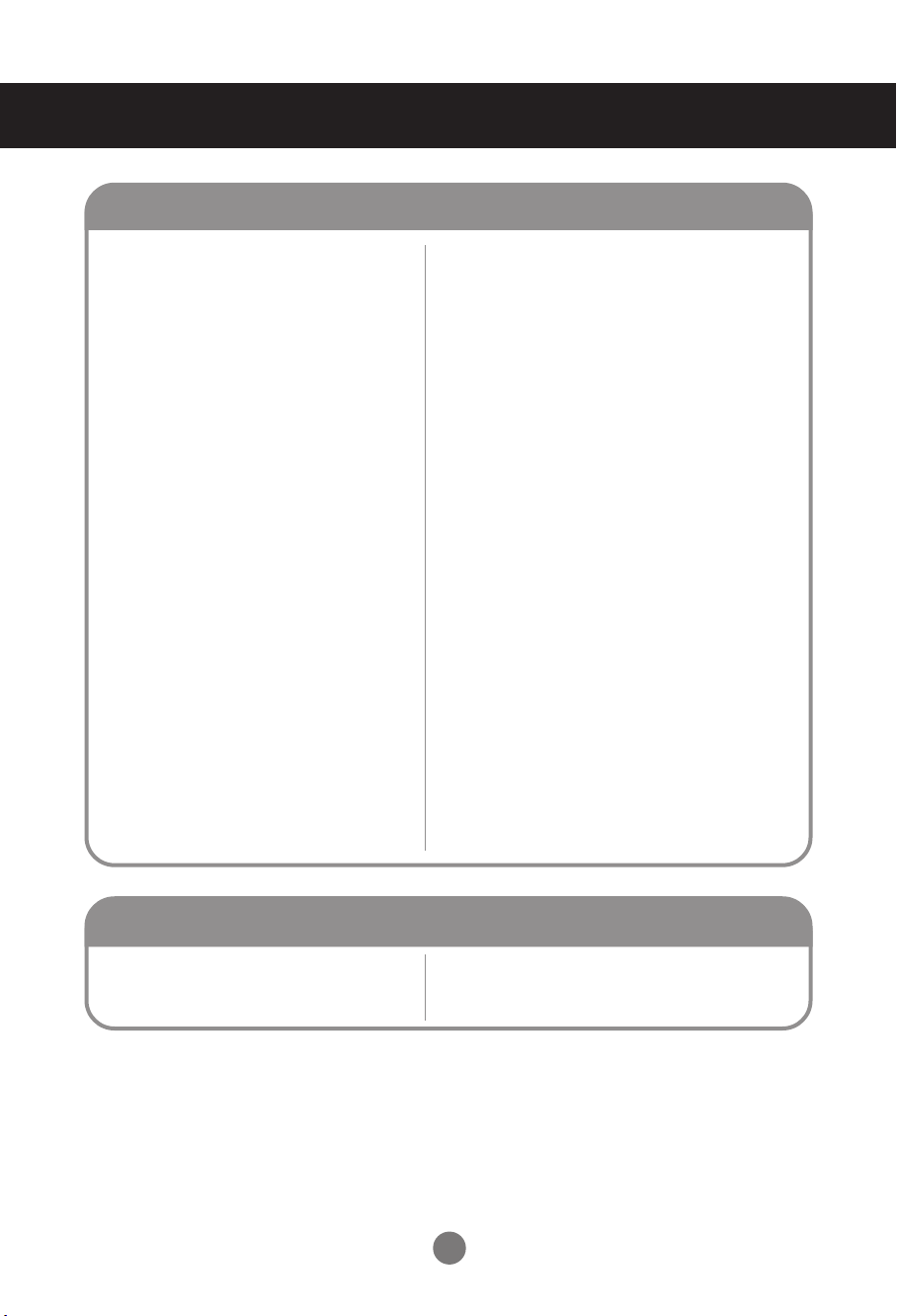
The screen image looks abnormal.
• D-Sub analog signal – Press the “AUTO” button in
the remote control to automatically select the
optimal screen status that fits into the current
mode. If adjustment is not satisfactory, use the
Position OSD menu.
• See if the video card resolution and frequency are
supported by the product. If the frequency is out of
range, set to the recommended resolution in the
Control Panel – Display – Setting menu.
• D-Sub analog signal – Press the “AUTO” button
in the remote control to automatically select an
optimal screen status that fits into the current
mode. If adjustment is not satisfactory, use the
Clock OSD menu.
• D-Sub analog signal – Press the “AUTO” button
in the remote control to automatically select an
optimal screen status that fits into the current
mode. If adjustment is not satisfactory, use the
Phase OSD menu.
• The proper input signal is not connected to the
signal port. Connect the signal cable that matches
with the source input signal.
• If you use a fixed image for a long time, the pixels
may be damaged quickly. Use the screen-saver
function.
●
After-image appears when the
product is turned off.
After-image appears on the product.
Troubleshooting
36
• Set the number of colors to more than 24 bits (true
color)
Select Control Panel – Display – Settings – Color
Table menu in Windows.
• Check the connection status of the signal cable.
Or, re-insert the PC video card.
• Several pixels (red, green, white or black color)
may appear on the screen, which can be
attributable to the unique characteristics of the
LCD panel. It is not a malfunction of the LCD.
●
Screen has poor color resolution
(16 colors).
●
Screen color is unstable or mono-
colored.
●
Do black spots appear on the screen?
Screen color is abnormal.
• See if the audio cable is connected properly.
• Adjust the volume.
• See if the sound is set properly.
• Select the appropriate equalize sound.
• Adjust the volume.
●
No sound?
●
Sound is too dull.
●
Sound is too low.
The audio function does not work.
Troubleshooting
• Is the sleep timer set?
• Check the power control settings.
Power interrupted.
•
"CAUTION! FAN STOP!"
If the power is turned off after this message
appears, it means that the fan is out of order.
In this case, contact your local service center.
●
The power suddenly turned off.
The operation does not work normally.
37
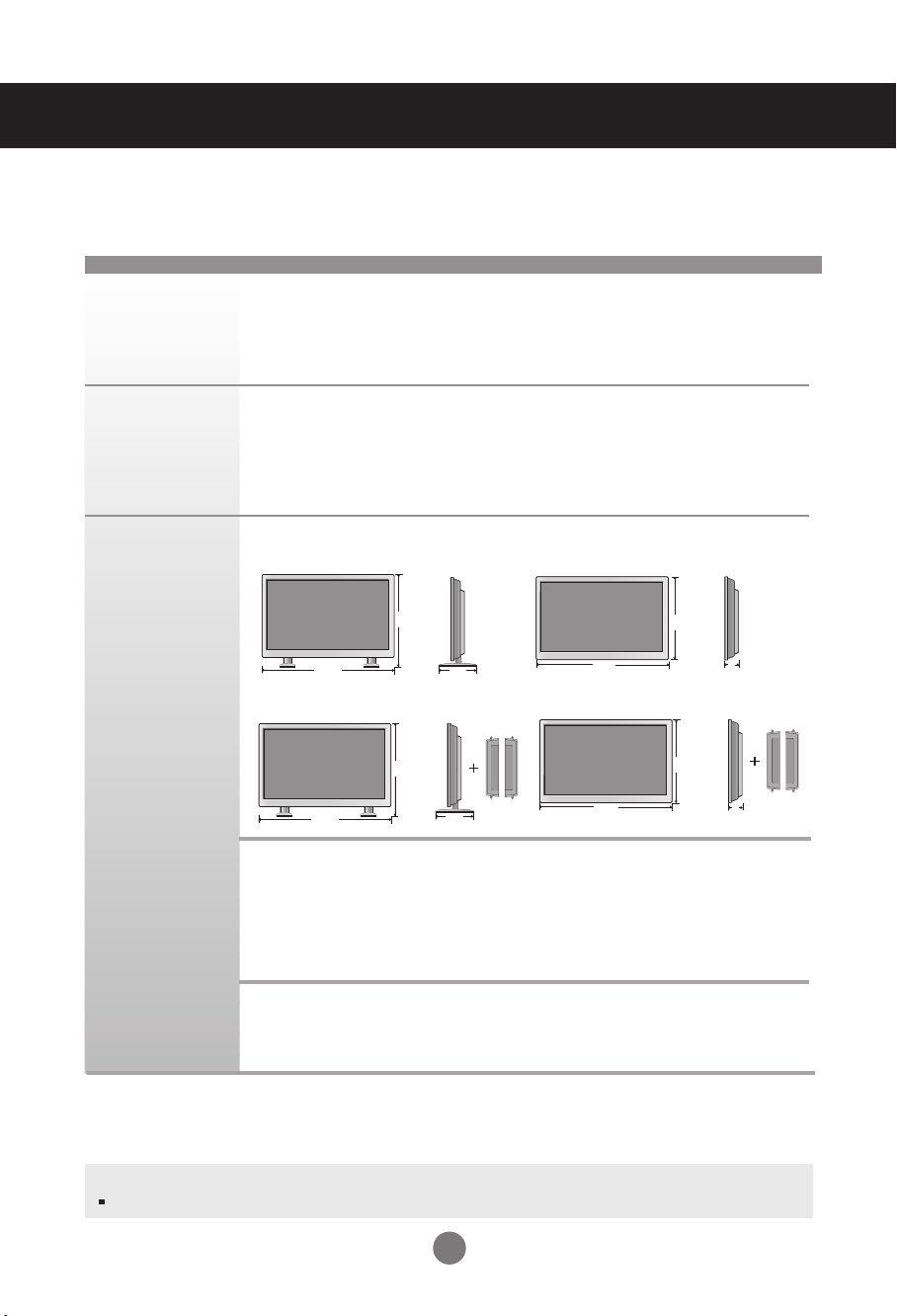
LCD Panel
Power
Dimensions
&Weight
Note
Information in this document is subject to change without notice.
106.731 cm (42.02 inch) TFT (Thin Film Transistor)
LCD (Liquid Crystal Display) Panel
Visible diagonal size: 106.731 cm
0.4845 mm x 0.4845 mm (Pixel Pitch)
Rated Voltage AC 100-240 V~ 50 / 60 Hz 2.2 A
Power Consumption On Mode : 220 W Typ.
Sleep Mode : ≤ 1 W (RGB) / 2 W(HDMI/DVI)
(If LAN OFF is selected)
Off Mode : ≤ 0.5 W
The product specifications can change without prior notice for product improvement.
Specifications
Width x Height x Depth
[1] 96.7 cm (38.07 inch) x 63.5 cm (24.99 inch) x 25.86 cm (10.18 inch)
[2] 96.7 cm (38.07 inch) x 55.98 cm (22.03 inch) x 12.369 cm (4.87 inch)
[3] 96.7 cm (38.07 inch) x 63.5 cm (24.99 inch) x 25.86 cm (10.18 inch)
[4] 96.7 cm (38.07 inch) x 55.98 cm (22.03 inch) x 12.369 cm (4.87 inch)
Net
[1] 19.92 kg (43.92 lb) [2] 18.64 kg (41.10 lb)
[3] 20.66 kg (45.55 lb) [4] 19.38 kg (42.73 lb)
[1]
W
H
[2]
W
H
D
D
[3]
W
H
D
D
[4]
W
H
M4224C
38
Specifications
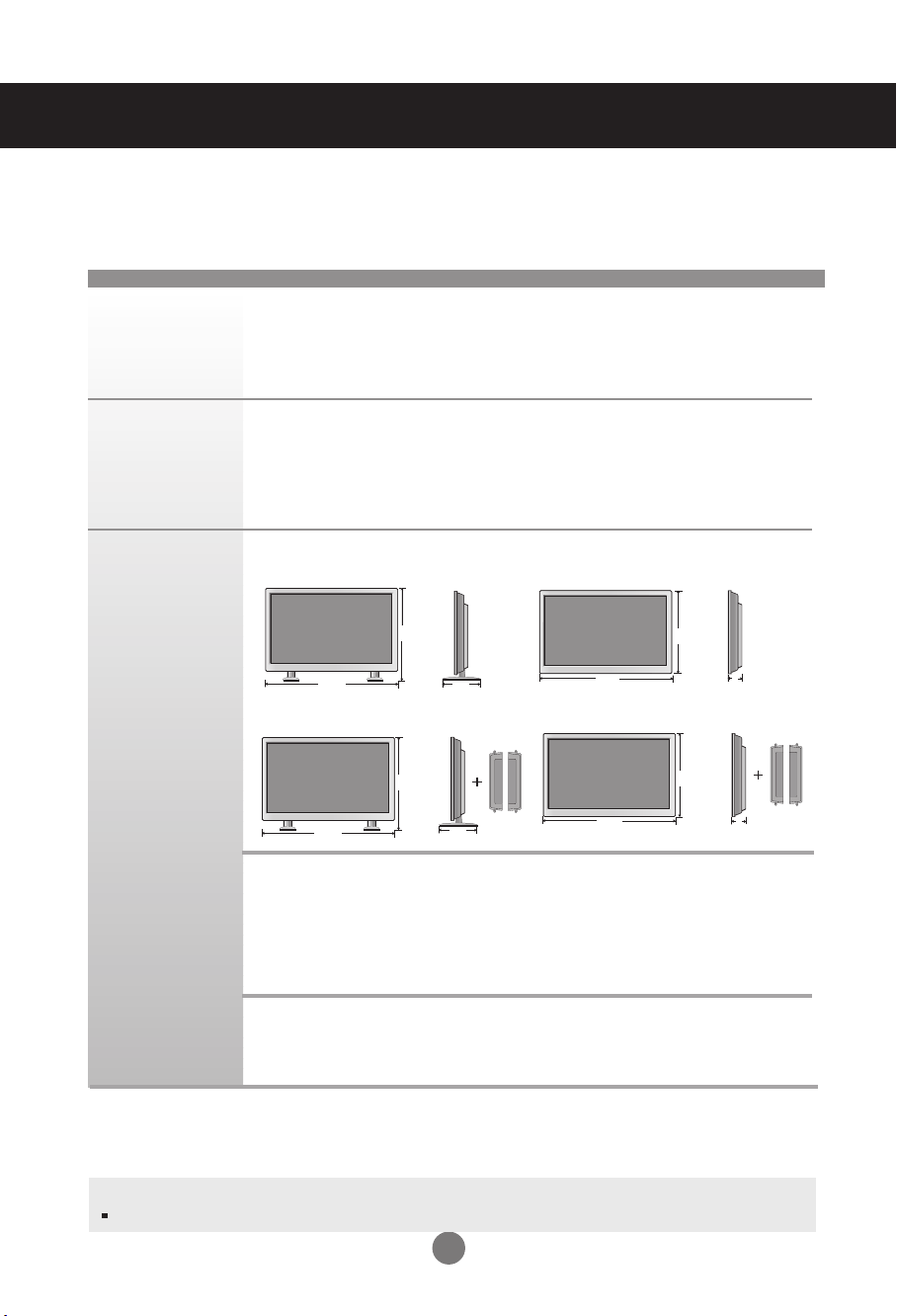
LCD Panel
Power
Dimensions
&Weight
Note
Information in this document is subject to change without notice.
106.731 cm (42.02 inch) TFT (Thin Film Transistor)
LCD (Liquid Crystal Display) Panel
Visible diagonal size: 106.731 cm
0.4845 mm x 0.4845 mm (Pixel Pitch)
Rated Voltage AC 100-240 V~ 50 / 60 Hz 2.2 A
Power Consumption On Mode : 220 W Typ.
Sleep Mode : ≤ 1 W (RGB) / 4 W(HDMI/DVI)
(If LAN OFF is selected)
Off Mode : ≤ 1 W
The product specifications can change without prior notice for product improvement.
Width x Height x Depth
[1] 96.7 cm (38.07 inch) x 63.5 cm (24.99 inch) x 25.86 cm (10.18 inch)
[2] 96.7 cm (38.07 inch) x 55.98 cm (22.03 inch) x 12.369 cm (4.87 inch)
[3] 96.7 cm (38.07 inch) x 63.5 cm (24.99 inch) x 25.86 cm (10.18 inch)
[4] 96.7 cm (38.07 inch) x 55.98 cm (22.03 inch) x 12.369 cm (4.87 inch)
Net
[1] 19.92 kg (43.92 lb) [2] 18.64 kg (41.10 lb)
[3] 20.66 kg (45.55 lb) [4] 19.38 kg (42.73 lb)
[1]
W
H
[2]
W
H
D
D
[3]
W
H
D
D
[4]
W
H
M4224F

39
Specifications
Note
Information in this document is subject to change without notice.
Max. Resolution RGB : 1920 x 1080 @ 60 Hz
HDMI/DVI :
1920 x 1080
@ 60 Hz – It may not be supported
depending on the OS or video card type.
Recommended Resolution
RGB : WSXGA 1920 x 1080 @ 60 Hz
HDMI/DVI : WSXGA 1920 x 1080 @ 60 Hz – It may not be
supported depending on the OS or video card type.
Horizontal Frequency RGB : 30 kHz to 83 kHz
HDMI/DVI : 30 kHz to 83 kHz
Vertical Frequency RGB : 56 Hz to 75 Hz
HDMI/DVI : 56 Hz to 60 Hz
Synchronization Type Composite/Separate/Digital
15-pin
D-Sub type, HDMI (digital), S-Video,
Composite Video, Component, RS-232C, LAN
Operational Condition Temperature: 0 ˚C to 40 ˚C , Humidity: 10 % to 80 %
Storage Condition Temperature: -20 ˚C to 60 ˚C , Humidity: 5 % to 90 %
Video Signal
Input Connector
Environmental
Conditions
The product specifications can change without prior notice for product improvement.
RMS Audio Output 10 W + 10 W (R+L)
Input Sensitivity 0.7 Vrms
Speaker Impedance 8 Ω
Audio
* Applicable only for models that support the speakers
40
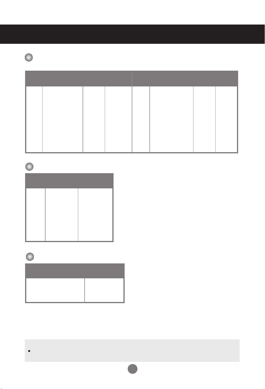
Preset mode
Horizontal
Frequency
(kHz)
Vertical
Frequency
(Hz)
PC Mode – Preset Mode
Preset mode
Horizontal
Frequency
(kHz)
Vertical
Frequency
(Hz)
1
2
*3
4
*5
6
7
*8
9
*10
640 x 350
720 x 400
640 x 480
640 x 480
800 x 600
800 x 600
832 x 624
1024 x 768
1024 x 768
1280 x 720
31.469
31.468
31.469
37.5
37.879
46.875
49.725
48.363
60.123
44.772
70.8
70.8
59.94
75
60.317
75
74.55
60
75.029
59.855
*11
*12
*13
*14
15
*16
*17
1280 x 768
1360 x 768
1366 x 768
1280 x 1024
1280 x 1024
1680 x 1050
1920 x 1080
47.7
47.72
47.7
63.981
79.98
65.290
67.5
60
59.799
60
60.02
75.02
59.954
60
Power
Indicator
Mode
Product
On Mode
Sleep Mode
Off Mode
Blue
Amber
-
1~17: RGB Mode
* : HDMI/DVI mode
Specifications
DTV Mode
Component
480i o x
576i o x
480p o o
576p o o
720p o o
1080i o o
1080p o o
HDMI/DVI(DTV)
Note
DTV/PC selection on RGB and HDMI/DVI inputs is available for PC resolutions :
640 x 480 / 60 Hz, 1280 x 720 / 60 Hz, 1920 x 1080 / 60 Hz and DTV resolutions : 480p, 720p, 1080p.
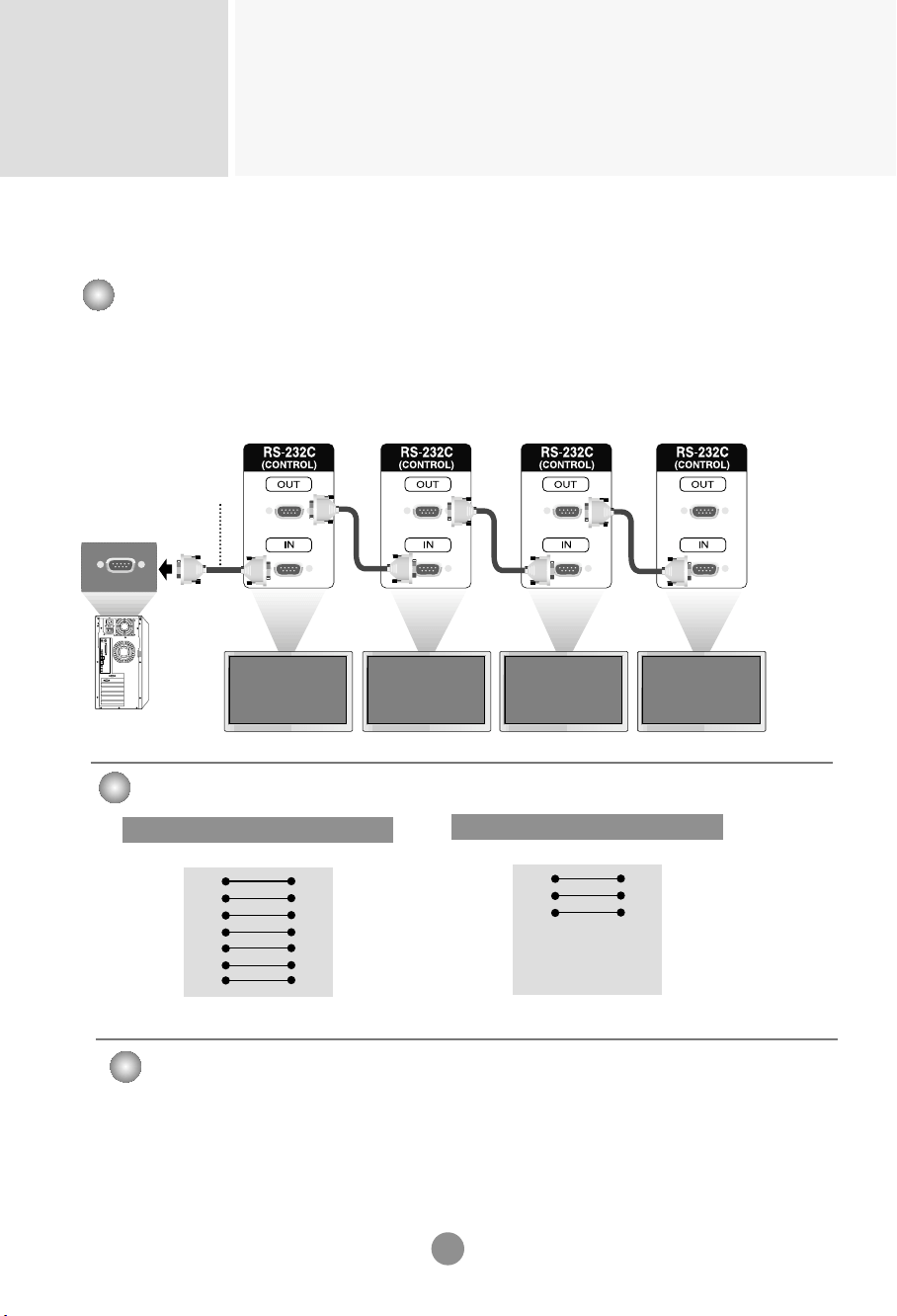
Controlling the Multiple Product
RS-232C
A1
Connecting the cable
Connect the RS-232C cable
as shown in the picture.
* The RS-232C protocol is used for communication between the PC and product. You can
turn the product on/off, select an input source or adjust the OSD menu from your PC.
Use this method to connect several products to a single PC.
You can control several products at a time by connecting them to a single PC.
RS-232C Cable
(not included)
monitor 1
PC
monitor 2
monitor 3 monitor 4
7-Wire Configurations (Standard RS-232C cable)
RXD
TXD
GND
DTR
DSR
RTS
CTS
TXD
RXD
GND
DSR
DTR
CTS
RTS
PC Monitor
2
3
5
4
6
7
8
3
2
5
6
4
8
7
D-Sub 9 D-Sub 9
(Female) (Female)
3-Wire Configurations (Not Standard)
RXD
TXD
GND
DTR
DSR
RTS
CTS
TXD
RXD
GND
DTR
DSR
RTS
CTS
PC Monitor
2
3
5
4
6
7
8
3
2
5
6
4
7
8
D-Sub 9 D-Sub 9
(Female) (Female)
Baud Rate : 9600buad Rate (UART)
Data Length : 8bits
Parity Bit : None
Stop Bit : 1bit
Flow Control : None
Communication Code : ASCII code
Use a crossed (reverse) cable
Communication Parameter
▲
▲
▲
▲
▲▲
▲
RS-232C Configurations
Controlling the Multiple Product
RS-232C
A2
Command Reference List
COMMAND1 COMMAND2 DATA1 DATA2 DATA3
01. Power k a 00H - 01H
02. Input Select k b 02H - 09H
03. Aspect Ratio k c 01H - 09H
04. Screen Mute k d 00H - 01H
05. Volume Mute k e 00H - 01H
06. Volume Control k f 00H - 64H
07. Contrast k g 00H - 64H
08. Brightness k h 00H - 64H
09. Color k i 00H - 64H
10. Tint k j 00H - 64H
11. Sharpness k k 00H - 64H
12. OSD Select k l 00H - 01H
13. Remote Lock/ key Lock k m 00H - 01H
14. Balance k t 00H - 64H
15. Color Temperature k u 00H - 03H
16. Abnormal state k z FFH
17. ISM mode j p 00H - 10H
18. Auto configuration j u 01H
19. Key m c Key Code
20. Tile Mode d d 00H - 55H
21. Tile H Position d e 00H - 64H
22. Tile V Position d f 00H - 64H
23. Tile H Size d g 00H - 64H
24. Tile V Size d h 00H - 64H
25. Tile ID Set d i 00H - 19H
26.
Natural Mode (In Tile mode)
d j 00H - 01H
27. Picture mode(PSM) d x 00H - 06H
28. Sound mode d y 00H - 06H
29. Fan Fault check d w FFH
30. Elapsed time return d l FFH
31. Temperature value d n FFH
32. Lamp fault check d p FFH
33. Auto Volume d u 00H - 01H
34. Speaker d v 00H - 01H
35. Time f a 00H - 06H 00H - 17H 00 - 3BH
36.
On Timer (On/Off Timer) On, Off
f b 00H, FFH 00H - FFH
37.
Off Timer (On/Off Timer) On, Off
f c 00H, FFH 00H - FFH
38.
On Timer (On/Off Timer) Time
f d 00H - 07H 00H - 17H 00 - 3BH
39.
Off Timer (On/Off Timer) Time
f e 00H - 07H 00H - 17H 00 - 3BH
40.
Sleep Time
f f 00H - 08H
41. Auto Sleep f g 00H - 01H
42. Power On Delay f h 00H - 64H
43. Language f i 00H - 09H
44. DPM Select f j 00H - 01H
45. Reset f k 00H - 02H
Controlling the Multiple Product
RS-232C
A3
COMMAND1 COMMAND2 DATA1 DATA2 DATA3
46. Power Saving f l 00H - 03H
47. Power Indicator f o 00H - 01H
48. H Position f q 00H - 64H
49. V Position f r 00H - 64H
50. H Size f s 00H - 64H
51. V Size f t 00H - 64H
52. Scheduling input select f u 00H - 07H 00H - FEH
53. Serial no. f y FFH
54. S/W Version f z FFH
55. Input Select x b 20H - A0H
Controlling the Multiple Product
RS-232C
A4
OK Acknowledgement
[Command2][ ][Set ID][ ][OK][Data][x]
* The Product transmits ACK (acknowledgement) based on
this format when receiving normal data. At this time, if the
data is data read mode, it indicates present status data.
If the data is data write mode, it returns the data of the PC
computer.
Error Acknowledgement
[Command2][ ][Set ID][ ][NG][Data][x]
* If there is error, it returns NG
Transmission
[Command1][Command2][ ][Set ID][ ][Data][Cr]
* [Command 1]: First command. (k, j, m, d, f,x)
* [Command 2]: Second command.(a ~ u)
* [Set ID]: Set up the Set ID number of product.
range : 01H~63H. by setting '0', server can control all products.
* In case of operating with more than 2 sets using set ID as '0' at the same
time, it should not be checked the ack message.
Because all sets will send the ack message, so it's impossible the check the
whole ack messages.
* [DATA]: To transmit command data.
Transmit 'FF' data to read status of command.
* [Cr]: Carriage Return
ASCII code ‘0x0D’
* [ ]: ASCII code Space (0x20)’
Transmission / Receiving Protocol
Controlling the Multiple Product
RS-232C
A5
Transmission / Receiving Protocol
01. Power(Command : a)
To control Power On/Off of the Set.
Transmission
[k][a][ ][Set ID][ ][Data][Cr]
Data 0 : Power Off 1 : Power On
Acknowledgement
[a][ ][Set ID][ ][OK][Data][x]
To show the status of Power On/Off.
Transmission
[k][a][ ][Set ID][ ][FF][Cr]
Acknowledgement
[a][ ][Set ID][ ][OK][Data][x]
Data 0 : Power Off 1 : Power On
02. Input Select (Command : b) (Main Picture Input)
To select input source for the Set.
You can also select an input source using the INPUT
button on the remote control.
Transmission
[k][b][ ][Set ID][ ][Data][Cr]
Data 2 : AV
4 : Component
7 : RGB (PC)
8 : HDMI (DTV)
9 : HDMI (PC)
Acknowledgement
[b][ ][Set ID][ ][OK][Data][x]
Data 2 : AV
4 : Component
7 : RGB (PC)
8 : HDMI (DTV)
9 : HDMI (PC)
▲
▲
▲
Controlling the Multiple Product
RS-232C
A6
03. Aspect Ratio(Command : c) (Main picture format)
To adjust the screen format.
You can also adjust the screen format using the ARC
(Aspect Ratio Control) button on remote control or in the
Screen menu.
Transmission
[k][c][ ][Set ID][ ][Data][Cr]
Data 1 : Normal Screen (4:3)
2 : Wide Screen (16 :9)
4 : Zoom1 (AV)
5 : Zoom2 (AV)
6 : Original (AV)
7 :14:9 (AV)
9 : Just Scan(HD DTV), 1:1 (RGB PC, HDMI/DVI PC)
Acknowledgement
[c][ ][Set ID][ ][OK][Data][x]
04. Screen Mute(Command : d)
To select screen mute on/off.
Transmission
[k][d][ ][Set ID][ ][Data][Cr]
Data 0 : Screen mute off (Picture on)
1 : Screen mute on (Picture off)
Acknowledgement
[d][ ][Set ID][ ][OK][Data][x]
Transmission / Receiving Protocol
▲
▲
Controlling the Multiple Product
RS-232C
A7
05. Volume Mute(Command : e)
To control On/Off of the Volume Mute.
Transmission
[k][e][ ][Set ID][ ][Data][Cr]
Data 0 : Volume Mute On (Volume Off)
1 : Volume Mute Off (Volume On)
Acknowledgement
[e][ ][Set ID][ ][OK][Data][x]
Data 0 : Volume Mute On (Volume Off)
1 : Volume Mute Off (Volume On)
06. Volume Control(Command : f)
To adjust Volume .
Transmission
[k][f][ ][Set ID][ ][Data][Cr]
Data Min : 00H ~ Max : 64H
(Hexadecimal code)
Acknowledgement
[f][ ][Set ID][ ][OK][Data][x]
Data Min : 00H ~ Max : 64H
•
Refer to ‘Real data mapping’ page A8.
Transmission / Receiving Protocol
▲▲
Controlling the Multiple Product
RS-232C
A8
Transmission / Receiving Protocol
07. Contrast(Command : g)
To adjust screen contrast.
You can also adjust the contrast in the Picture menu.
Transmission
[k][g][ ][Set ID][ ][Data][Cr]
Data Min : 00H ~ Max : 64H
•
Refer to ‘Real data mapping’ as shown below.
Acknowledgement
[g][ ][Set ID][ ][OK][Data][x]
* Real data mapping
0 : Step 0
:
A : Step 10
:
F : Step 15
10 : Step 16
:
64 : Step 100
08. Brightness(Command : h)
To adjust screen brightness.
You can also adjust the brightness in the Picture menu.
Transmission
[k][h][ ][Set ID][ ][Data][Cr]
Data Min : 00H ~ Max : 64H
•
Refer to ‘Real data mapping’ as shown below.
Acknowledgement
[h][ ][Set ID][ ][OK][Data][x]
* Real data mapping
0 : Step
:
A : Step 10
:
F : Step 15
10 : Step 16
:
64 : Step 100
▲▲
Controlling the Multiple Product
RS-232C
A9
Transmission / Receiving Protocol
09. Color(Command : i) (Video Timing only)
To adjust the screen color.
You can also adjust the color in the Picture menu.
Transmission
[k][i][ ][Set ID][ ][Data][Cr]
Data Min : 00H ~ Max : 64H
(Hexadecimal code)
•
Refer to ‘Real data mapping’ page A8.
Acknowledgement
[i][ ][Set ID][ ][OK][Data][x]
Data Min : 00H ~ Max : 64H
10. Tint(Command : j) (Video Timing only)
To adjust the screen tint.
You can also adjust the tint in the Picture menu.
Transmission
[k][j][ ][Set ID][ ][Data][Cr]
Data Red: 00H ~ Green: 64H
(Hexadecimal code)
•
Refer to ‘Real data mapping’ page A8.
Acknowledgement
[j][ ][Set ID][ ][OK][Data][x]
Data Red: 00H ~ Green: 64H
* Tint Real data mapping
0 : Step 0 - Red
:
64 : Step 100 - Green
▲
▲
Controlling the Multiple Product
RS-232C
A10
11. Sharpness(Command : k) (Video Timing only)
To adjust the screen Sharpness.
You can also adjust the sharpness in the Picture menu.
Transmission
[k][k][ ][Set ID][ ][Data][Cr]
Data Min : 00H ~ Max : 64H
(Hexadecimal code)
•
Refer to ‘Real data mapping’ page A8.
Acknowledgement
[k][ ][Set ID][ ][OK][Data][x]
Data Min : 00H ~ Max : 64H
12. OSD Select(Command : l)
To control OSD on/off to the set.
Transmission
[k][l][ ][Set ID][ ][Data][Cr]
Data 0 : OSD Off 1 : OSD On
Acknowledgement
[l][ ][Set ID][ ][OK][Data][x]
Data 0 : OSD Off 1 : OSD On
13. Remote Lock /Key Lock (Command : m)
To control Remote Lock on/off to the set.
This function, when controlling RS-232C, locks the remote control and the local keys.
Transmission
[k][m][ ][Set ID][ ][Data][Cr]
Data 0 : Off 1 : On
Acknowledgement
[m][ ][Set ID][ ][OK][Data][x]
Data 0 : Off 1 : On
Transmission / Receiving Protocol
▲
▲
▲

Controlling the Multiple Product
RS-232C
A11
Transmission / Receiving Protocol
14 Balance(Command : t)
To adjust the sound balance.
Transmission
[k][t][ ][Set ID][ ][Data][Cr]
Data Min : 00H ~ Max : 64H
(Hexadecimal code)
•
Refer to ‘Real data mapping’ page A8.
Acknowledgement
[t][ ][Set ID][ ][OK][Data][x]
Data Min : 00H ~ Max : 64H
* Balance : L50 ~ R50
15. Color Temperature (Command : u)
To adjust the screen color temperature.
Transmission
[k][u][ ][Set ID][ ][Data][Cr]
Data 0 : Medium
1 : Cool
2 : Warm
3 : User
Acknowledgement
[u][ ][Set ID][ ][OK][Data][x]
Data 0 : Medium
1 : Cool
2 : Warm
3 : User
•
Running the Color Temperature command changes the Picture Mode settings to User1.
▲
▲
Controlling the Multiple Product
RS-232C
A12
Transmission / Receiving Protocol
16. Abnormal state (Command : z)
Abnormal State : Used to Read the power off status when Stand-by mode.
Transmission
[k][z][ ][Set ID][ ][Data][Cr]
Data FF : Read
0 : Normal (Power on and signal exist)
1 : No signal (Power on)
2 : Turn the monitor off by remote control
3 : Turn the monitor off by sleep time function
4 : Turn the monitor off by RS-232C function
8 : Turn the monitor off by off time function
9 : Turn the monitor off by auto off function
Acknowledgement
[z][ ][Set ID][ ][OK][Data][x]
17. ISM mode(Command: j p)
Used to select the afterimage preventing function.
Transmission
[j][p][ ][Set ID][ ][Data][Cr]
Data 1H : Inversion
2H : Orbiter
4H : White Wash
8H : Normal
10H : Dot Wash
Acknowledgement
[p][ ][Set ID][ ][OK][Data][x]
▲
▲
Controlling the Multiple Product
RS-232C
A13
18. Auto Configure(Command: j u)
To adjust picture position and minimize image shaking
automatically. it works only in RGB(PC) mode.
Transmission
[j][u][ ][Set ID][ ][Data][Cr]
Data 1 : To set
Acknowledgement
[u][ ][Set ID][ ][OK][Data][x]
Transmission / Receiving Protocol
▲
19. Key(Command : m c)
To send IR remote key code.
Transmission
[m][c][ ][Set ID][ ][Data][Cr]
Data Key code : Refer to page A34.
Acknowledgement
[c][ ][Set ID][ ][OK][Data][x]
▲
Controlling the Multiple Product
RS-232C
A14
20. Tile Mode(Command : d d)
Change a Tile Mode.
Transmission
[d][d][][Set ID][][Data][x]
* The data can not be set to 0X or X0 except 00.
Acknowledgement
[d][][00][][OK/NG][Data][x]
Transmission / Receiving Protocol
Data Description
00 or 11 Tile mode is off.
12 1 x 2 mode(column x row)
13 1 x 3 mode
14 1 x 4 mode
... ...
55 5 x 5 mode
▲

Controlling the Multiple Product
RS-232C
A15
21. Tile H Position(Command : d e)
To set the Horizontal position.
Transmission
[d][e][][Set ID][][Data][x]
Data Min : 00H ~ Max : 64H
•
Refer to ‘Real data mapping’ page A8.
Acknowledgement
[e][][Set ID][][OK/NG][Data][x]
22. Tile V Position(Command : d f)
To set the Vertical position.
Transmission
[d][f][][Set ID][][Data][x]
Data Min : 00H ~ Max : 64H
•
Refer to ‘Real data mapping’ page A8.
Acknowledgement
[f][][Set ID][][OK/NG][Data][x]
Transmission / Receiving Protocol
▲
▲
Controlling the Multiple Product
RS-232C
A16
23. Tile H Size(Command : d g)
To set the Horizontal size.
Transmission
[d][g][][Set ID][][Data][x]
Data Min : 00H ~ Max : 64H
•
Refer to ‘Real data mapping’ page A8.
Acknowledgement
[g][][Set ID][][OK/NG][Data][x]
24. Tile V Size(Command : d h)
To set the Vertical size.
Transmission
[d][h][][Set ID][][Data][x]
Data Min : 00H ~ Max : 64H
•
Refer to ‘Real data mapping’ page A8.
Acknowledgement
[h][][Set ID][][OK/NG][Data][x]
Transmission / Receiving Protocol
▲
▲
Controlling the Multiple Product
RS-232C
A17
25. Tile ID Set(Command : d i)
To assign the Tile ID for Tiling function .
Transmission
[d][i][][Set ID][][Data][x]
Data Min : 00H ~ Max : 19H
(Hexadecimal code)
Acknowledgement
[i][][Set ID][][OK/NG][Data][x]
26
Natural Mode (In Tile mode) (
Command : d j)
To assign the Tile Natural mode for Tiling function .
Transmission
[d][j][][Set ID][][Data][x]
Data 0 : Natural Off
1 : Natural On
ff : Read Status
Acknowledgement
[j][][Set ID][][OK/NG][Data][x]
Transmission / Receiving Protocol
▲▲
27. Picture Mode (Command : d x)
To adjust the picture mode.
Transmission
[d][x][][Set ID][][Data][x]
Data Structure
Acknowledgement
[x][][Set ID][][OK/NG][Data][x]
▲
Data(Hex)
00
01
02
03
04
05
06
MODE
Vivid
Standard
Cinema
Sport
Game
User1
User2
Controlling the Multiple Product
RS-232C
A18
Transmission / Receiving Protocol
28. Sound Mode (Command : d y )
To adjust the Sound mode.
Transmission
[d][y][][Set ID][][Data][x]
Data Structure
Acknowledgement
[y][][Set ID][][OK/NG][Data][x]
▲
Data(Hex)
00
01
02
03
04
05
06
Mode
Clear Voice
Standard
Music
Cinema
sport
Game
User
29. Fan Fault check (Command : d w )
To check the Fan fault of the TV.
Transmission
[d][w][][Set ID][][Data][x]
* The data is always FF(in Hex).
Data ff: Read Status
Acknowledgement
[w][][Set ID][][OK/NG][Data][x]
* Data is the status value of the Fan fault.
Data 0: Fan fault
1: Fan OK
2: N/A(Not Avaliable)
▲
Controlling the Multiple Product
RS-232C
A19
31. Temperature value (Command : d n)
To read the inside temperature value.
Transmission
[d][n][][Set ID][][Data][x]
* The data is always FF(in Hex).
Acknowledgement
[n][][Set ID][][OK/NG][Data][x]
* The data is 1 byte long in Hexadecimal.
32. Lamp fault Check(Command : d p)
To check lamp fault.
Transmission
[d][p][][Set ID][][Data][x]
* The data is always FF(in Hex).
Acknowledgement
[p][][Set ID][][OK/NG][Data][x]
Data 0 : Lamp Fault
1: Lamp OK
Transmission / Receiving Protocol
▲
▲
30. Elapsed time return(Command : d l)
To read the elapsed time.
Transmission
[d][l][][Set ID][][Data][x]
* The data is always FF(in Hex).
Acknowledgement
[l][][Set ID][][OK/NG][Data][x]
* The data means used hours.
(Hexadecimal code)
▲
Controlling the Multiple Product
RS-232C
A20
33. Auto volume (Command : d u)
Automatically adjust the volume level.
Transmission
[d][u][][Set ID][][Data][x]
Data 0 : Off
1 : On
Acknowledgement
[u][][Set ID][][OK/NG][Data][x]
34. Speaker (Command : d v)
Turn the speaker on or off.
Transmission
[d][v][][Set ID][][Data][x]
Data 0 : Off
1 : On
Acknowledgement
[v][][Set ID][][OK/NG][Data][x]
Transmission / Receiving Protocol
▲
▲
Controlling the Multiple Product
RS-232C
A21
35. Time (Command : f a)
Set the current time.
Transmission
[f][a][][Set ID][][Data1][][Data2][][Data3][Cr]
[Data1]
0 : Monday
1 : Tuesday
2 : Wednesday
3 : Thursday
4 : Friday
5 : Saturday
6 : Sunday
[Data2]
0H~17H (Hours)
[Data3]
00H~3BH (Minutes)
Acknowledgement
[a][][Set ID][][OK/NG][Data1][Data2][Data3][x]
*When reading data, FFH is inputted for [Data1], [Data2] and [Data3].
In other cases, all are treated as NG.
Transmission / Receiving Protocol
▲
Controlling the Multiple Product
RS-232C
A22
36. On Timer (On/Off Timer) On, Off (Command : F b)
Set days for On Timer.
Transmission
[f][b][][Set ID][][Data1][][Data2][Cr]
[Data1]
0 (Write), FFH(Read)
[Data2]
00H~FFH
bit0 : Monday On Timer On(1), Off(0)
bit1 : Tuesday On Timer On(1), Off(0)
bit2 : Wednesday On Timer On(1), Off(0)
bit3 : Thursday On Timer On(1), Off(0)
bit4 : Friday On Timer On(1), Off(0)
bit5 : Saturday On Timer On(1), Off(0)
bit6 :Sunday On Timer On(1), Off(0)
bit7 : Everyday On Timer On(1), Off(0)
Acknowledgement
[b][][Set ID][][OK/NG][Data1][Data2][x]
▲
Transmission / Receiving Protocol
* Ignore from bit6 to bit0 when bit7(Everyday) is 1.
* Ignore from bit6 to bit0 when bit7(Everyday) is 1.
37. Off Timer (On/Off Timer) On, Off (Command : f c)
Set days for Off Timer.
Transmission
[f][c][][Set ID][][Data1][][Data2][Cr]
[Data1]
0 (Write), FFH(Read)
[Data2]
00H~FFH
bit0 : Monday Off Timer On(1), Off(0)
bit1 : Tuesday Off Timer On(1), Off(0)
bit2 : Wednesday Off Timer On(1), Off(0)
bit3 : Thursday Off Timer On(1), Off(0)
bit4 : Friday Off Timer On(1), Off(0)
bit5 : Saturday Off Timer On(1), Off(0)
bit6 :Sunday Off Timer On(1), Off(0)
bit7 : Everyday Off Timer On(1), Off(0)
Acknowledgement
[c][][Set ID][][OK/NG][Data1][Data2][x]
▲
Controlling the Multiple Product
RS-232C
A23
38. On Timer (On/Off Timer) Time (Command : f d)
Set On Timer.
Transmission
[f][d][][Set ID][][Data1][][Data2][Data3][Cr]
[Data1]
0 : Monday
1: Tuesday
2 : Wednesday
3 : Thursday
4 : Friday
5 : Saturday
6 : Sunday
7 : Everyday
[Data2]
00H~17H (Hours)
[Data3]
00H~3BH (Minutes)
Acknowledgement
[d][][Set ID][][OK/NG][Data1][Data2][Data3][x]
*When reading data, FFH is inputted for [Data2], [Data3].
In other cases, all are treated as NG.
Transmission / Receiving Protocol
▲
Controlling the Multiple Product
RS-232C
A24
39. Off Timer (On/Off Timer) Time (Command : f e)
Set Off Timer.
Transmission
[f][e][][Set ID][][Data1][][Data2][][Data3][Cr]
[Data1]
0 : Monday
1 : Tuesday
2 : Wednesday
3 : Thursday
4 : Friday
5 : Saturday
6 : Sunday
7 : Everyday
[Data2]
00H~17H (Hours)
[Data3]
00H~3BH (Minutes)
Acknowledgement
[e][][Set ID][][OK/NG][Data1][Data2][Data3][x]
*When reading data, FFH is inputted for [Data2], [Data3].
In other cases, all are treated as NG.
Transmission / Receiving Protocol
▲
Controlling the Multiple Product
RS-232C
A25
40. Sleep Time (Command : f f)
Set Sleep Time.
Transmission
[f][f][][Set ID][][Data][Cr]
Data
0 : Off
1 : 10
2 : 20
3 : 30
4 : 60
5 : 90
6 : 120
7 : 180
8 : 240
(Orderly)
Acknowledgement
[f][][Set ID][][OK/NG][Data][x]
▲
Transmission / Receiving Protocol
41. Auto Sleep (Command : f g)
Set Auto Sleep.
Transmission
[f][g][][Set ID][][Data][Cr]
Data 0 : Off
1: On
Acknowledgement
[g][][Set ID][][OK/NG][Data][x]
▲
Controlling the Multiple Product
RS-232C
A26
42. Power On Delay (Command : f h)
Set the schedule delay when the power is turned on (Unit: second).
Transmission
[f][h][][Set ID][][Data][Cr]
Data : 00H ~ 64H (Data value)
•
Refer to ‘Real data mapping’ page A8.
Acknowledgement
[h][][Set ID][][OK/NG][Data][x]
Transmission / Receiving Protocol
▲
43. Language (Command : f i)
Set the OSD language.
Transmission
[f][i][][Set ID][][Data][Cr]
Data
0 : English
1 : French
2 : German
3 : Spanish
4 : Italian
5 : Portuguese
6 : Chinese
7 : Japanese
8 : Korean
9 : Russian
Acknowledgement
[i][][Set ID][][OK/NG][Data][x]
▲
Controlling the Multiple Product
RS-232C
A27
44. DPM Select (Command : f j)
Set the DPM (Display Power Management) function.
Transmission
[f][j][][Set ID][][Data][Cr]
Data 0 : Off
1: On
Acknowledgement
[j][][Set ID][][OK/NG][Data][x]
Transmission / Receiving Protocol
▲
45. Reset (Command : f k)
Execute the Picture, Screen and Factory Reset functions.
Transmission
[f][k][][Set ID][][Data][Cr]
Data
0 : Picture Reset
1 : Screen Reset
2 : Factory Reset
Acknowledgement
[k][][Set ID][][OK/NG][Data][x]
▲
Controlling the Multiple Product
RS-232C
A28
46. Power saving(Command : f I)
To set the Power saving mode.
Transmission
[f][I][][Set ID][][Data][Cr]
Data 0 : Off
1: (static level 1)
2: (static level 2)
3: (static level 3)
Acknowledgement
[I][][Set ID][][OK/NG][Data][x]
Transmission / Receiving Protocol
▲
47. Power Indicator (Command : f o)
To set the LED for Power Indicator
Transmission
[f][o][][Set ID][][Data][Cr]
Data 0 : Off
1: On
Acknowledgement
[o][][Set ID][][OK/NG][Data][x]
▲
48. H Position (Command : f q)
To set the Horizontal position
Transmission
[f][q][][Set ID][][Data][Cr]
* The data range is from 00 to 64(in Hex)
•
Refer to ‘Real data mapping’ page A8.
Acknowledgement
[q][][Set ID][][OK/NG][Data][x]
▲
Controlling the Multiple Product
RS-232C
A29
Transmission / Receiving Protocol
49. V Position (Command : f r)
To set the Horizontal position
Transmission
[f][r][][Set ID][][Data][Cr]
* The data range is from 00 to 64(in Hex)
•
Refer to ‘Real data mapping’ page A8.
Acknowledgement
[r][][Set ID][][OK/NG][Data][x]
▲
50. H Size (Command : f s)
To set the Horizontal size.
Transmission
[f][s][][Set ID][][Data][Cr]
* The data range is from 00 to 64(in Hex)
•
Refer to ‘Real data mapping’ page A8.
Acknowledgement
[s][][Set ID][][OK/NG][Data][x]
▲
* H Size Real Data Mapping
[Data1]
0x00: Step 0
0x0A: Step 10
0x14: Step 20
0x1E: Step 30
0x28: Step 40
0x32: Step 50
0x3C: Step 60
0x46: Step 70
0x50: Step 80
0x5A: Step 90
0x64: Step 100
Controlling the Multiple Product
RS-232C
A30
Transmission / Receiving Protocol
51. V Size (Command : f t)
To set the Vertical size
Transmission
[f][t][][Set ID][][Data][Cr]
* The data range is from 00 to 64(in Hex)
•
Refer to ‘Real data mapping’ page A8.
Acknowledgement
[t][][Set ID][][OK/NG][Data][x]
▲
* V Size Real Data Mapping
[Data1]
0x00: Step 0
0x0A: Step 10
0x14: Step 20
0x1E: Step 30
0x28: Step 40
0x32: Step 50
0x3C: Step 60
0x46: Step 70
0x50: Step 80
0x5A: Step 90
0x64: Step 100
Controlling the Multiple Product
RS-232C
A31
53. Serial no.Check (Command : f y)
To read the serial numbers
Transmission
[f][y][][Set ID][][Data][Cr]
Data FF (to read the serial numbers)
Acknowledgement
[y][][Set ID][][OK/NG][Data1] ~ [Data13] [x]
▲
Transmission / Receiving Protocol
52. Scheduling Input select (Command : f u) (Main Picture Input)
To select input source for TV depending on day.
Transmission
[f][u][][Set ID][][Data1][][Data2][Cr]
Data 1 Structure
Min: 0~Max:7(0:Monday, 1: Tuesday, 2: Wednesday, 3: Thursday, 4: Friday
5: Saturday, 6: Sunday, 7: Everyday)
Data 2 Structure
Acknowledgement
[u][][Set ID][][OK/NG][Data 1][Data 2][x]
▲
Data(Hex)
02
04
07
08
09
FE
INPUT
AV
Component
RGB-PC
HDMI/DVI-DTV
HDMIDVI-PC
No change
* The data format is ASCII Code.
Controlling the Multiple Product
RS-232C
A32
54. S/W Version (Command : f z)
Check the software version.
Transmission
[f][z][][Set ID][][Data][Cr]
Data FFH : Read
Acknowledgement
[z][][Set ID][][OK/NG][Data][x]
Transmission / Receiving Protocol
▲
55. Input Select (Command : x b)
To select input source for the Set.
Transmission
[x][b][ ][Set ID][ ][Data][Cr]
Data 20H : AV
40H : Component
60H : RGB (PC)
90H : HDMI/DVI (DTV)
A0H : HDMI/DVI (PC)
Acknowledgement
[b][ ][Set ID][ ][OK][Data][x]
Data 20H : AV
40H : Component
60H : RGB (PC)
90H : HDMI/DVI (DTV)
A0H : HDMI/DVI (PC)
▲
IR Codes
RS-232C
A33
How to connect
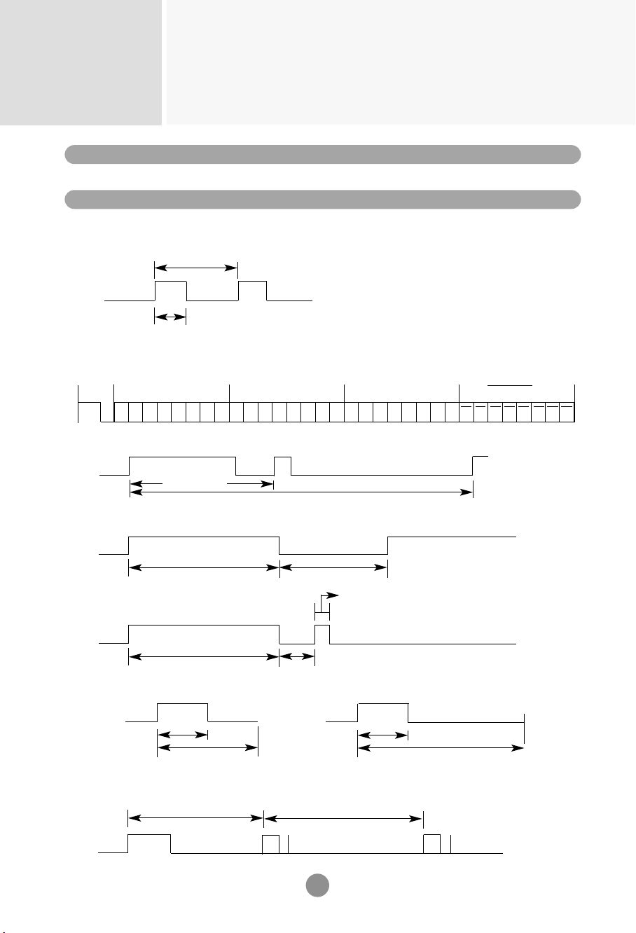
Remote Control IR Code
Connect your wired remote control to Remote Control port on the Product.
Output waveform
single pulse, modulated with 37.917KHz signal at 455KHz
Carrier frequency
FCAR = 1/Tc = fosc/12
Duty ratio = T1/Tc = 1/3
Configuration of frame
•
1st frame
T1
Lead
code
Low
custom code
High
custom code
Data code
Data code
C0 C1 C2 C3 C4 C5 C6 C7 C0 C1 C2 C3 C4 C5 C6 C7 D0 D1 D2 D3 D4 D5 D6 D7 D0 D1 D2 D3 D4 D5 D6 D7
Tc
Tf
•
Repeat frame
Repeat code
Lead code
Repeat code
9ms
Bit description
•
Bit "0"
•
Bit "1"
2.25ms
9ms
0.55ms
0.56ms
1.12ms
0.56ms
2.24ms
Frame interval : Tf
•
The waveform is transmitted as long as a key is depressed.
Tf
Tf
Tf=108ms@455KHz
4.5ms
▲▲▲
▲
▲
▲
▲

RS-232C
A34
▲
▲
00
01
02
03
08
C4
C5
09
98
0B
0E
43
5B
6E
44
10
11
12
13
14
15
16
17
18
19
5A
BF
D5
C6
79
76
77
AF
99
▲
▼
VOL( )
VOL( )
POWER ON/OFF
POWER ON
POWER OFF
MUTE
AV
INPUT
SLEEP
MENU
EXIT
PSM
SET
Number Key 0
Number Key 1
Number Key 2
Number Key 3
Number Key 4
Number Key 5
Number Key 6
Number Key 7
Number Key 8
Number Key 9
AV
COMPONENT
RGB PC
HDMI/DVI
ARC
ARC (4:3)
ARC (16:9)
ARC (ZOOM)
AUTO CONFIG
R/C Button
R/C Button
R/C Button
R/C Button
R/C Button (Power On/Off)
Discrete IR Code(Only Power On)
Discrete IR Code(Only Power Off)
R/C Button
R/C Button
R/C Button
R/C Button
R/C Button
R/C Button
R/C Button
R/C Button
R/C Button
R/C Button
R/C Button
R/C Button
R/C Button
R/C Button
R/C Button
R/C Button
R/C Button
R/C Button
Discrete IR Code(Input AV Selection)
Discrete IR Code(Input COMPONENT Selection)
Discrete IR Code(Input RGB PC Selection)
Discrete IR Code(Input HDMI/DVI Selection)
R/C Button
Discrete IR Code(Only 4:3 mode)
Discrete IR Code(Only 16:9 mode)
Discrete IR Code(Only ZOOM1, ZOOM2 mode)
Discrete IR Code
Code(Hex) Function Note
IR Codes

Make sure to read the Important Precautions
before using the product.
Keep the User’s Guide(CD) in an accessible
place for furture reference.
The model and serial number of the SET is
located on the back and one side of the SET.
Record it below should you ever need service.
Temporary noise is normal when powering ON
or OFF this device.
MODEL
SERIAL