
i

VAIO Digital Studio System Reference Manual
ii
NOTICE
© 2003 Sony Electronics Inc. Reproduction in whole
or in part without written permission is prohibited.
All rights reserved. This manual and the software
described herein, in whole or in part, may not be
reproduced, translated, or reduced to any machine-
readable form without prior written approval.
SONY ELECTRONICS INC. PROVIDES NO
WARRANTY WITH REGARD TO THIS
MANUAL, THE SOFTWARE, OR OTHER
INFORMATION CONTAINED HEREIN AND
HEREBY EXPRESSLY DISCLAIMS ANY
IMPLIED WARRANTIES OF
MERCHANTABILITY OR FITNESS FOR ANY
PARTICULAR PURPOSE WITH REGARD TO
THIS MANUAL, THE SOFTWARE, OR SUCH
OTHER INFORMATION. IN NO EVENT SHALL
SONY ELECTRONICS INC. BE LIABLE FOR
ANY INCIDENTAL, CONSEQUENTIAL, OR
SPECIAL DAMAGES, WHETHER BASED ON
TORT, CONTRACT, OR OTHERWISE, ARISING
OUT OF OR IN CONNECTION WITH THIS
MANUAL, THE SOFTWARE, OR OTHER
INFORMATION CONTAINED HEREIN OR THE
USE THEREOF.
SONY CANNOT WARRANT THAT THE
FUNCTIONS DESCRIBED IN THIS GUIDE WILL
BE UNINTERRUPTED OR ERROR-FREE. SONY
ALSO ASSUMES NO RESPONSIBILITY, AND
SHALL NOT BE LIABLE FOR ANY DAMAGES
TO, OR VIRUSES THAT MAY INFECT, YOUR
COMPUTER EQUIPMENT, OR OTHER
PROPERTY ON ACCOUNT OF YOUR ACCESS
TO, USE OF, OR BROWSING IN ANY
DESCRIBED WEB SITE, OR YOUR
DOWNLOADING OF ANY MATERIALS, DATA,
TEXT, IMAGES, VIDEO, OR AUDIO FROM ANY
DESCRIBED WEB SITE. WEB SITE
INFORMATION IS OBTAINED FROM VARIOUS
SOURCES AND MAY BE INACCURATE. COPIES
OF COPYRIGHTED INFORMATION MAY ONLY
BE MADE FOR LEGALLY PERMISSIBLE
PURPOSES.
Sony Electronics Inc. reserves the right to make any
modification to this manual or the information
contained herein at any time without notice. The
software described herein is governed by the terms of
a separate user license agreement.
This product contains software owned by Sony and
licensed by third parties. Use of such software is
subject to the terms and conditions of license
agreements enclosed with this product. Some of the
software may not be transported or used outside the
United States. Software specifications are subject to
change without notice and may not necessarily be
identical to current retail versions.
Certain product(s) included with this computer may
include features such as copy protection and content
management technology. USE OF THE SOFTWARE
PRODUCT(S) REQUIRES AGREEMENT TO
APPLICABLE END USER AGREEMENTS AND
FULL COMPLIANCE WITH APPLICABLE
PRODUCT ACTIVATION PROCEDURES. Product
activation procedures and privacy policies will be
detailed during initial launch of the software
product(s), or upon certain reinstallations of the
software product(s), or reconfigurations of the
computer, and may be completed by Internet or
telephone (toll charges may apply).
Updates and additions to software may require an
additional charge. Subscriptions to online service
providers may require a fee and credit card
information. Financial services may require prior
arrangements with participating financial
institutions.
Important information for Canadian customers:
Your new VAIO computer includes certain software
versions or upgrades, and Internet services or offers
that are available to U.S. customers only.
Sony, VAIO, the VAIO logo, VAIO Smart, Giga
Pocket, MovieShaker, DVgate, Handycam, Memory
Stick, the Memory Stick logo, Net MD, Network
Walkman, OpenMG, MICROMV, SonicStage,
ImageStation, ATRAC3, and i.LINK are trademarks
or registered trademarks of Sony.
Intel and Pentium are trademarks or registered
trademarks of the Intel Corporation. Microsoft,
Windows, the Windows logo and Windows XP are
trademarks or registered trademarks of the Microsoft
Corporation. PS/2 is a registered trademark of the
IBM Corporation.
All other trademarks are trademarks or registered
trademarks of their respective owners.
iii
The International ENERGY STAR® Office
Equipment Program is an international program that
promotes energy saving through the use of computers
and other office equipment. The program backs the
development and dissemination of products with
functions that effectively reduce energy
consumption. It is an open system in which business
proprietors can participate voluntarily. The targeted
products are office equipment such as computers,
displays, printers, facsimiles and copiers. Their
standards and logos are uniform among participating
nations.
ENERGY STAR is a U.S. registered
trademark of the Environmental Protection Agency.
Owner’s Record
The model number and serial number are located on
the back panel of your Sony VAIO® computer.
Record the model and serial number in the space
provided here, and keep in a secure location. Refer to
the model and serial numbers when you call your
Sony Service Center.
As an ENERGY
STAR® Partner, Sony
Corporation has
determined that this
product meets the
ENERGY STAR®
guidelines for energy
efficiency.
Model Number:
Serial Number:

ix
Disposal of Lithium Battery
You can return your unwanted lithium batteries to
your nearest Sony Service Center or Factory Service
Center.
For the Sony Service Center nearest you, call
1-888-476-6972 in the United States or
1-800-961-7669 in Canada.
✍ In some areas the disposal of lithium
batteries in household or business trash
may be prohibited.
! Do not handle damaged or
leaking lithium batteries. In some
areas, the disposal of lithium
batteries in household or
business trash may be
prohibited.
! Danger of explosion if battery is
incorrectly replaced. Replace
only with the same or equivalent
type recommended by the
manufacturer. Discard used
batteries according to the
manufacturer’s instructions.
! The battery pack used in this
device may present a fire or
chemical burn hazard if
mistreated. Do not disassemble,
heat above 212°F (100°C), or
incinerate. Dispose of used
battery promptly. Keep away
from children.
! Ne pas manipuler les batteries au
lithium qui fuient ou sont
endommagées.
! Une batterie non conforme
présente un danger d'explosion.
La remplacer seulement par une
batterie identique ou de type
équivalent recommandé par le
fabricant. Évacuer les batteries
usées selon les directives du
fabricant.
! La manutention incorrecte du
module de batterie de cet
appareil présente un risque
d'incendie ou de brûlures
chimiques. Ne pas démonter,
incinérer ou exposer à une
température de plus de 100°C.
Évacuer promptement la batterie
usée. Garder hors de portée des
enfants.

VAIO Digital Studio System Reference Manual
x
Industry Canada Notice
This equipment meets the applicable Industry
Canada technical specifications.
The Ringer Equivalence Number (REN) is an
indication of the maximum number of devices
allowed to be connected to a telephone interface. The
termination on an interface may consist of any
combination of devices subject only to the
requirement that the sum of the RENs of all the
devices does not exceed 5.
Avis de l’Industrie Canada
Le presént matériel est conforme aux spécifications
techniques applicables d’Industrie Canada.
L’indice d’équivalence de la sonnerie (IES) sert à
indiquer le nombre maximal de terminaux qui
peuvent être raccordés à une interface téléphonique.
La terminaison d’une interface peut consister en une
combinaison quelconque de dispositifs, à la seule
condition que la somme d’indices d’équivalence de
la sonnerie de tous les dispositifs n’excède pas 5.

xi
Contents
NOTICE ....................................................................................................... ii
Owner’s Record.................................................................................. iii
Safety Information and Caution ...................................................... iv
Regulatory Information.................................................................... vii
FCC Part 68 ....................................................................................... viii
Telephone Consumer Protection Act of 1991
(United States) ..................................................................................viii
Telephone Consumer Guidelines (Canada)................................. viii
Disposal of Lithium Battery ..............................................................ix
Industry Canada Notice......................................................................x
Avis de l’Industrie Canada.................................................................x
Chapter 1 — Identifying Components................................1
Front View (PCV-RZ Series model)..........................................................2
Drives.....................................................................................................3
Buttons and Switches ..........................................................................4
Indicators...............................................................................................5
Connectors (Models Equipped with Giga Pocket Features)..........6
Rear View
(Model Equipped with Giga Pocket Features)........................................7
Icon Labels ............................................................................................8
I/O Connectors ..................................................................................10
Expansion Slots ..................................................................................14
Chapter 2 — Configuring Your System ............................15
Accessing the BIOS Setup Utility............................................................16
Changing Power Management Settings ................................................17

VAIO Digital Studio System Reference Manual
xiv

1
Chapter 1
Identifying Components
The following sections identify and describe each component that is
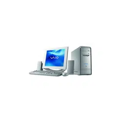
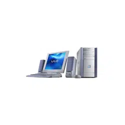
visible from the exterior of the VAIO® Digital Studio™ computer. Your
computer's components may vary, based on the model and features you
purchased. Your computer may not be equipped with all of these
hardware features and the location of the controls, ports, and jacks may
vary from the illustrations shown in this section. For details on the
hardware configuration of your system, see the online specifications
sheet.
To view this the online specifications sheet:
1 Click Start in the Windows taskbar, then click Help and Support.
2 From the VAIO Help and Support menu, click VAIO User Guide.
3 Locate the link in the text, “View the VAIO® Computer
Specifications, which lists your computer's hardware configuration
and preinstalled software information.”

VAIO Digital Studio System Reference Manual
2
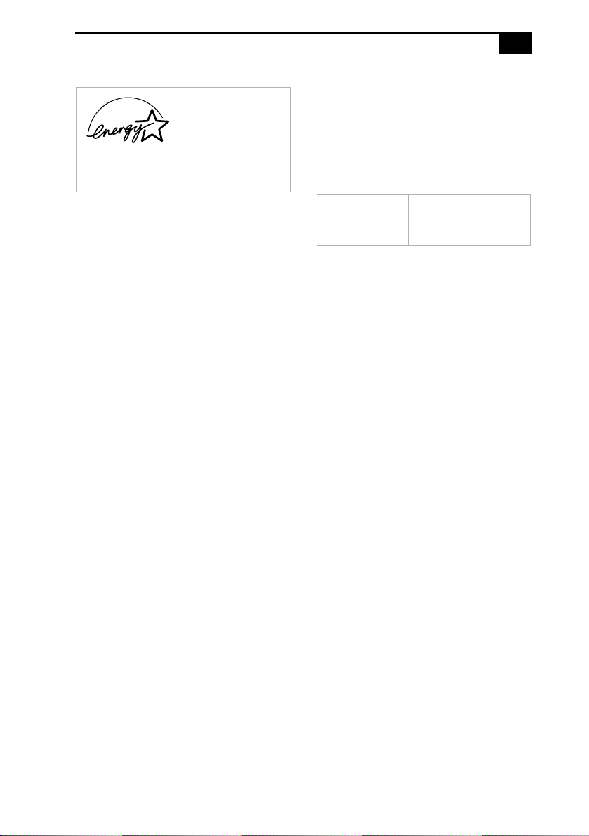
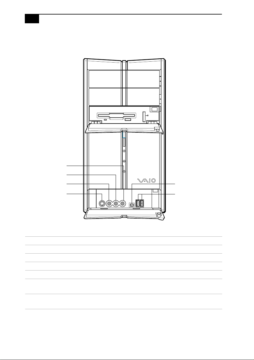
Front View (PCV-RZ Series model)
VAIO Digital Studio System Reference Manual
4
Buttons and Switches
Button or switch Description
Optical disc eject button Automatically opens and closes the optical drive
tray.
Floppy disk eject button Ejects a floppy disk.
Power on/off switch Turns system power on, off, or into Stand by
mode.
Optical disc eject
Floppy disk eject
Power on/off
Identifying Components
5
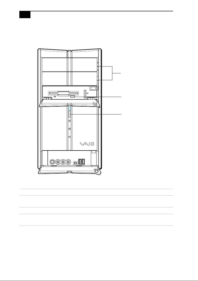
Indicators
Indicator Description
Floppy disk drive access
indicator
Light is green while reading and writing
data from and to a floppy disk.
Power indicator Light is blue while the power is on.
Standby indicator Light is red when the computer is placed
in Standby mode.
Optical disc drive access
indicator
Light is amber while reading and writing
data from and to the optical drives.
Hard disk drive access
indicator
Light is amber while reading and writing
data from and to the hard disk.
Floppy disk drive access
Hard disk drive access
Optical disc drive access
Power
Standby
VAIO Digital Studio System Reference Manual
6
Connectors (Models Equipped with Giga Pocket Features)
Connector Description
Audio R In jack
*
* The audio and video connections are available only on models equipped with Giga Pocket™
features.
Connects to an audio cable (supplied).
Audio L In jack
*
Connects to an audio cable (supplied).
Video In jack
*
Connects to a video cable (supplied).
S-Video In jack
*
Connects to an S-video cable (optional).
i.LINK®
(IEEE 1394) port
†
† To connect to a 6-pin i.LINK device, use the 6-pin i.LINK port on the back of the system. A 6-pin
i.LINK cable can supply power from the computer to the device if the device also has a 6-pin i.LINK
port. A 4-pin i.LINK cable cannot supply power to the device.
Connects to a digital device that has a 4-pin i.LINK
connector.
USB1, USB2 ports Connects to compatible high/full/low-speed USB
devices.
USB1, USB2 ports
i.LINK port
S-Video In jack
Video In jack
Audio L In jack
Audio R In jack

Identifying Components
7
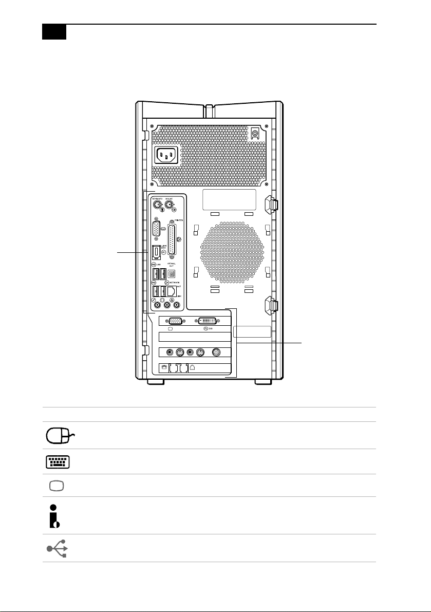
Rear View
(Model Equipped with Giga Pocket Features)
MONITOR
USB
LINEPHONE
HEADPHONES
MIC
LINE IN
VHF/UHF
AUDIO
–
VIDEO OUTPUT
–
AUDIO
–
VIDEO1 INPUT
–
S VIDEO/VIDEO S VIDEO/VIDEO
MONITOR
Mouse port
Keyboard port
Ethernet port
USB3, USB4,
Printer port
S/P DIF
i.LINK port
Microphone,
VGA Monitor port
AV Out jacks
AV In jacks
Modem line jack
AC Input
port
VHF/UHF
port
Out port
Telephone jack
Speaker
DVI Monitor port
DC Out jack
Line In jacks
VGA Monitor port
(Not available
on all models)
(Not available on
all models)
USB5, USB6 ports
Headphone,
VAIO Digital Studio System Reference Manual
8
Icon Labels
Icon Description
Mouse port
Keyboard port
VGA Monitor port
i.LINK® S400 (IEEE 1394) port
Universal Serial Bus (USB 2.0) ports
MONITOR
USB
LINEPHONE
HEADPHONES
MIC
LINE IN
VHF/UHF
AUDIO
–
VIDEO OUTPUT
–
AUDIO
–
VIDEO1 INPUT
–
S VIDEO/VIDEO S VIDEO/VIDEO
MONITOR
Icon Label Area
Icon Label Area
Identifying Components
11
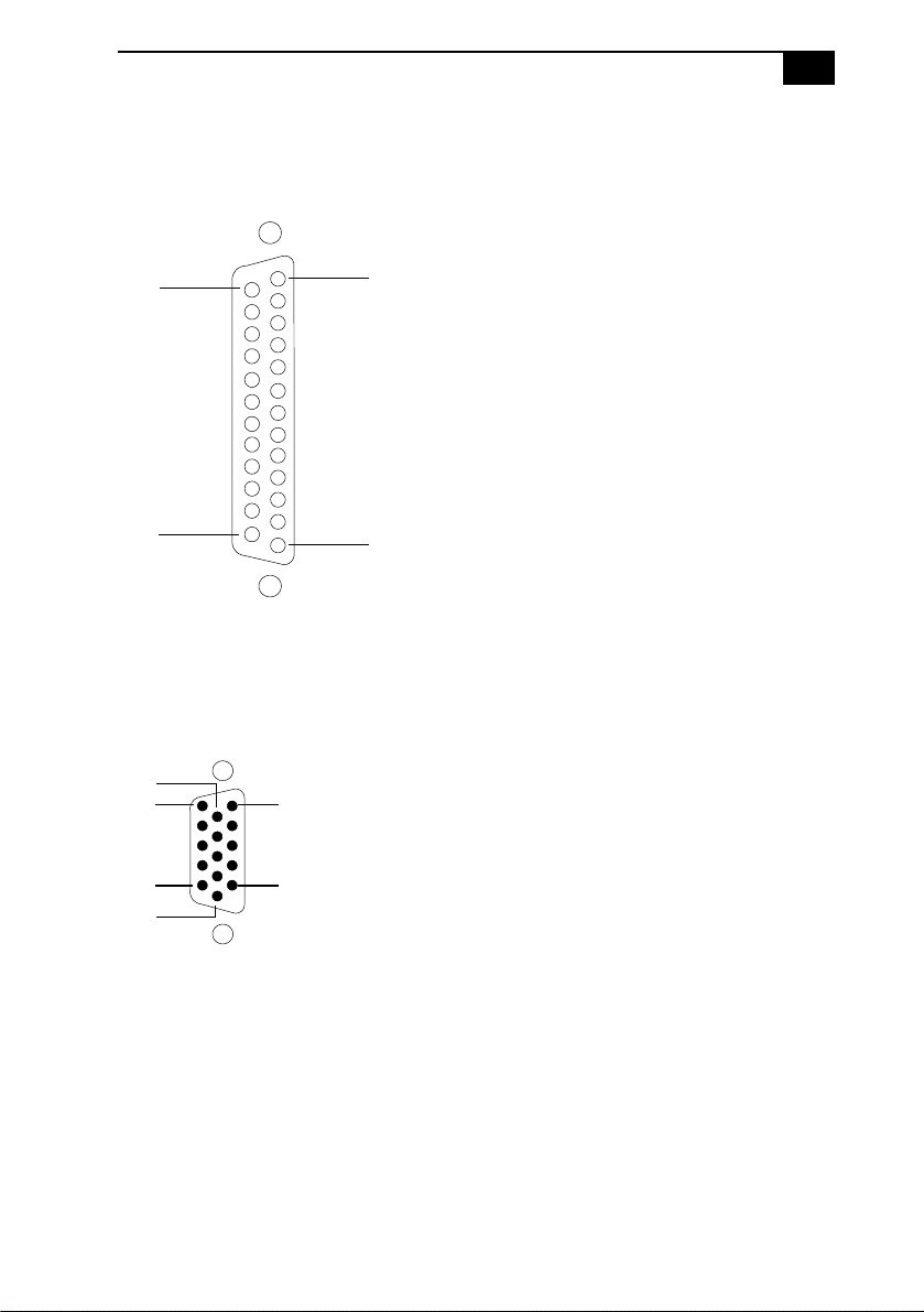
Printer Port
The printer port is a standard 25-pin DB-25 female port.
VGA Monitor Port
The monitor port is a standard 15-pin female high-density VGA-type port
located on the AGP plug-in card.
25
14
13
1
5
1
10
15
11
6
VAIO Digital Studio System Reference Manual
12
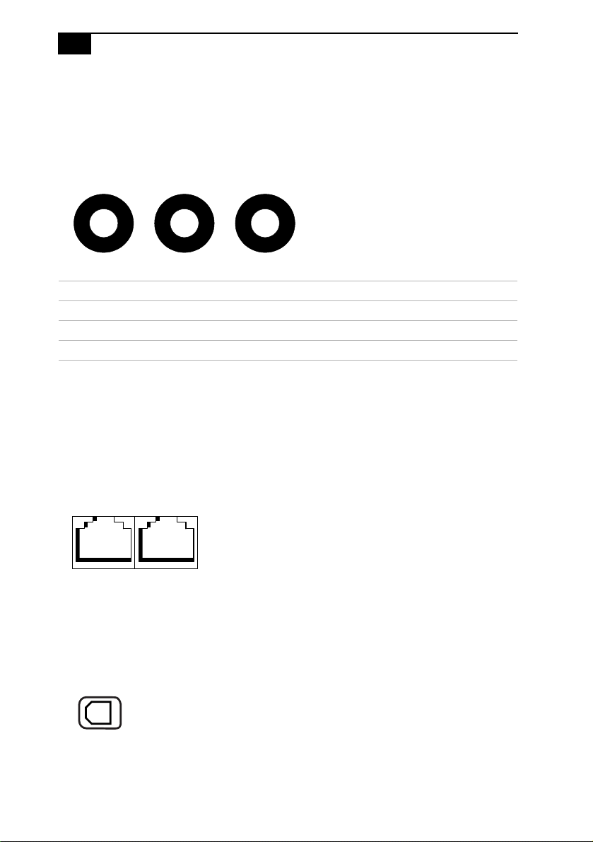
Microphone, Headphones, and Line In Jacks
The microphone, headphones, and line in jacks are physically identical,
but have different connections. They are standard 3.5 mm stereo
mini-jacks.
Telephone and Modem Line Jacks
The telephone and modem line jacks are physically identical and have
identical connections. They are standard RJ-11 female phone jacks.
However, the line jack is for connecting a telephone line that comes from
the wall to the computer, and the telephone jack is for connecting the
telephone to a computer.
S/P DIF Optical Out Port
The Plastic Optical Fiber (POF) output port for the Sony®/Phillips
Digital Interface (S/P DIF) can be used to connect compatible audio or
video equipment, such as CD/DVD players or MiniDisc recorders.
Connector Description
Microphone Electret condenser microphone input.
Headphones 1.0 Vrms (typical).
Line In 1.0 Vrms (typical), 10 Kohm impedance.
Headphones Line InMicrophone
ModemTelephone
Line Line

Identifying Components
13
i.LINK S400 (IEEE 1394) Ports
The 6-pin i.LINK® port on the back panel of the system can supply power
from the computer to an i.LINK device if the device also has a 6-pin
i.LINK port. The 6-pin port supplies 10 V to 12 V and a maximum power
of 6 watts.
Refer to the documentation that came with your compatible i.LINK
device for information on operating conditions and proper connections.
Before connecting compatible i.LINK devices to your system, such as an
optical disc or hard disk drive, confirm their operating system
compatibility and required operating conditions.
The 4-pin i.LINK port at the bottom of the front panel does not supply
power to an i.LINK device.
Speaker DC Out Jack
The Speaker DC Out jack on the back panel of the system is the
connection for the supplied speaker power cable.
✍ i.LINK is a trademark of Sony used only to designate that a product contains an
IEEE 1394 connection. The i.LINK connection may vary, depending on the software
applications, operating system and compatible i.LINK devices. All products with an i.LINK
connection may not communicate with each other.
6-pin i.LINK port
(IEEE 1394)
On back of
system
4-pin i.LINK port
(IEEE 1394)
Behind lower
front panel

15
Chapter 2
Configuring Your System
This chapter contains information on configuring your system.
❑ Making changes to the BIOS settings.
❑ Making changes to the display's power management settings.

VAIO Digital Studio System Reference Manual
16
Accessing the BIOS Setup Utility
Access the BIOS Setup Utility to make changes to the BIOS settings (see
“CMOS Setup Options” on page 57 for information on BIOS settings).
1 Reboot your computer by selecting Shut Down... from the Start
menu, then select Restart.
2 When the Sony logo appears, press F3. The following message
appears at the bottom of the screen.
Press <F2> for setup.
3 Press F2.
Each menu presents options for modifying the system configuration.
Use the left and right arrow keys to select a menu from the menu bar.
Use the up and down arrow keys to select items within a menu. Once
an item is highlighted, use the plus/minus (+/-) keys to modify a
setting.
If an item has a triangle ( ) to its left, this indicates that a sub-menu of
options is available. Press ENTER to access a sub-menu. If a sub-
menu contains items with a triangle, there is another layer of options
from which to select.
4 Once you select an option, press ESC to back out of each menu until
you reach the top level, where the menu bar appears.
5 To exit the BIOS setup utility, press ESC from any top-level screen and
follow the prompts.
! Before rebooting the system, save and close all open files, and exit open
applications.
Configuring Your System
17
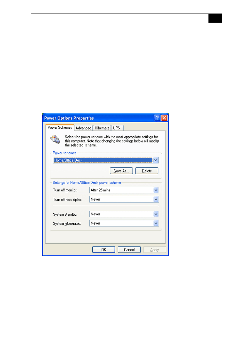
Changing Power Management Settings
Power Management capability is designed to enable your computer to
reduce power or shut itself off after being idle for a specified period of
time.
1 From the Start menu, point to Settings, click Control Panel, then
click Display.
The Power Options Properties dialog box opens, with the Power
Schemes tab displayed.
Configuring Your System
19
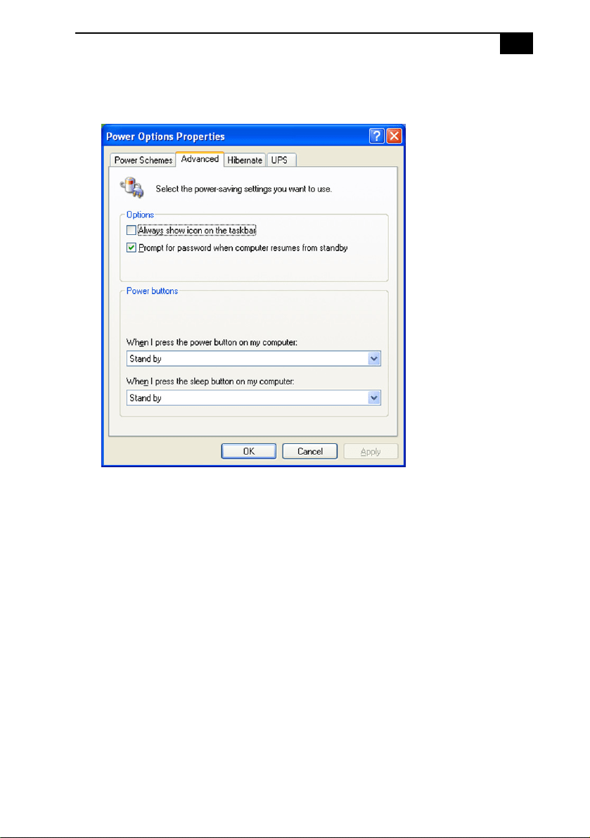
4 Click the Advanced tab.
5 Select the desired settings.

VAIO Digital Studio System Reference Manual
20
6 Click the Hibernate tab.
7 Select the settings most appropriate for your system.

VAIO Digital Studio System Reference Manual
22

23
Chapter 3
Upgrading and Maintaining
Components
This chapter describes upgrade and maintenance procedures.
! Before opening the system unit, save and close all open files, exit all open
applications, turn off the power to all attached peripheral devices, shut
down the computer, and unplug the power cord.
✍ System configuration may vary, depending on the model purchased. Your computer may
not include all of the hardware features shown in the illustrations of this section.
VAIO Digital Studio System Reference Manual
24
Removing the Side Panel
You must remove the side panel to access the system board, add-on cards,
power supply, battery, memory, and internal drives.
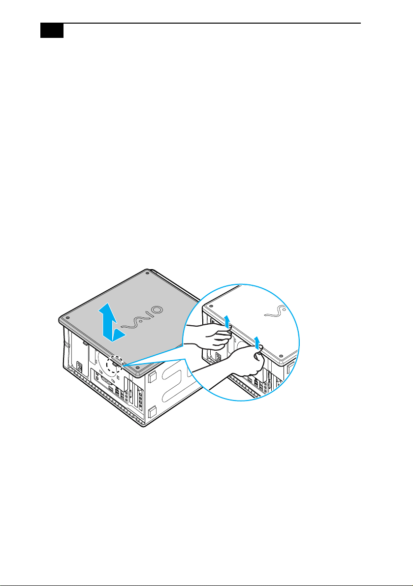
To remove the side panel (PCV-RZ series model)
1 Shut down your computer and turn off all peripheral devices, such as
your printer.
2 Unplug your computer and disconnect any peripheral devices.
3 Locate the two tabs on the back edge of the right side panel.
4 Press up on these tabs and slide the side panel towards you.
5 Lift up the side panel and set aside.
Removing the side panel (PCV-RZ series model equipped with Giga Pocket)
Upgrading and Maintaining Components
25
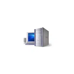
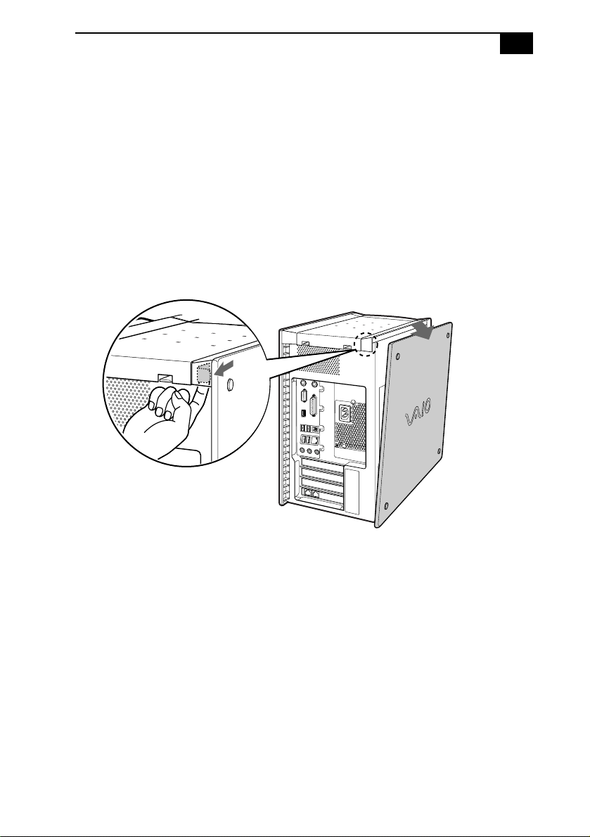
To remove the side panel (PCV-RX series model)
1 Shut down your computer and turn off all peripheral devices, such as
your printer.
2 Unplug your computer and any peripheral devices.
3 Locate the tab on the upper right side of the rear panel, and pull it
back until the side panel releases.
4 Lift the side panel away from the unit and set aside.
Removing the side panel (PCV-RX series model)
VAIO Digital Studio System Reference Manual
26
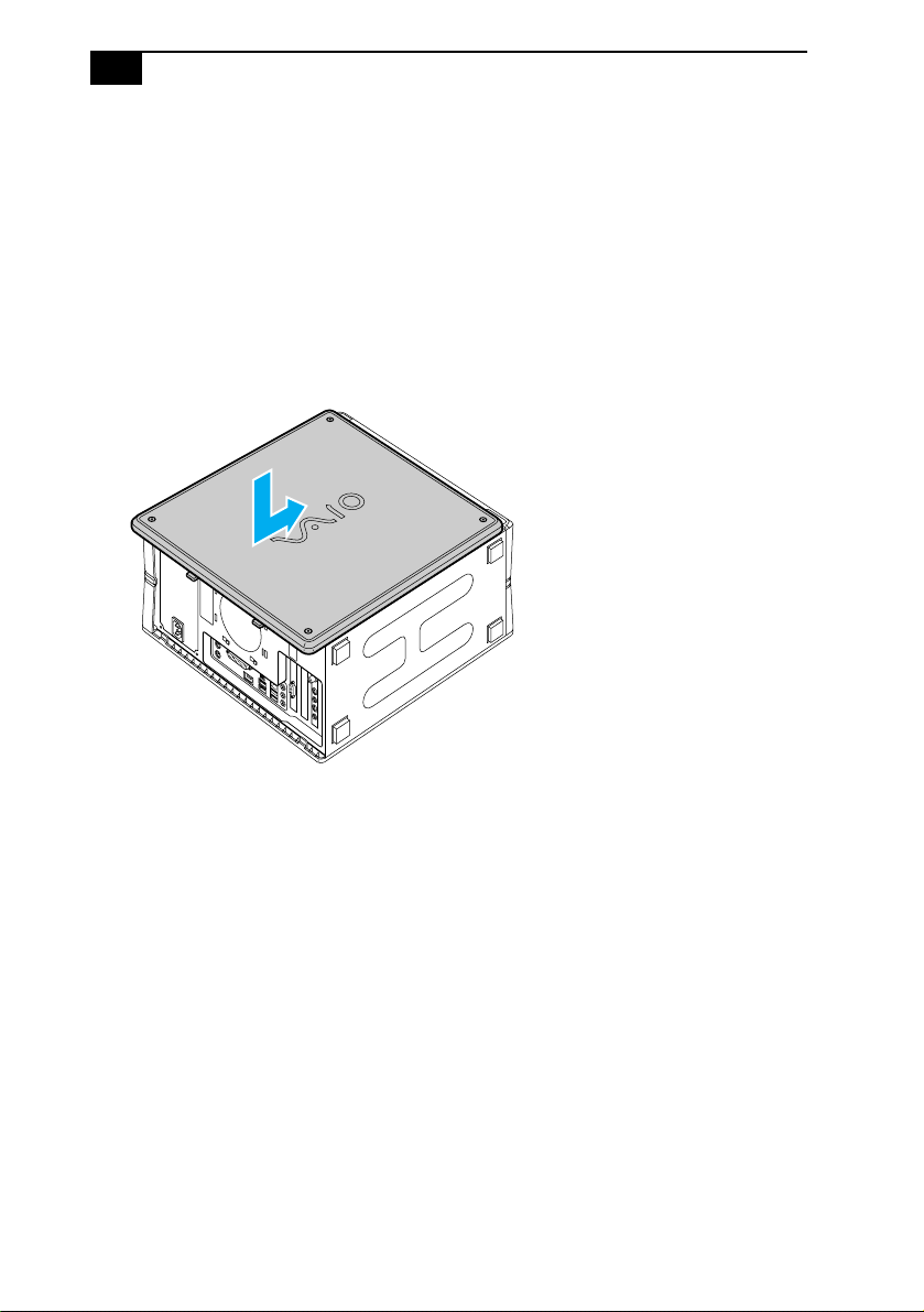
Replacing the Side Panel
To replace the side panel (PCV-RZ series model)
1 Align tabs on the side panel to the tracks on the chassis frame.
2 Gently slide the side panel onto the chassis, until the tabs lock the
panel into place.
Replacing the side panel (PCV-RZ series model equipped with Giga Pocket)

VAIO Digital Studio System Reference Manual
28
Installing an Add-on Card
Your computer may have one or more open expansion slots, depending
on the model configuration. An expansion slot enables you to install
add-on cards to expand the functionality of your system. The length of
the add-on card should not exceed 9.05 inches.
To install an add-on card
1 Shut down your computer and turn off all peripheral devices, such as
your printer.
2 Unplug your computer and any peripheral devices.
3 Remove the side panel.
4 Locate an available expansion slot. Remove the slot cover's screw,
and then remove the slot cover.
✍ Add-on card configuration varies by model. Some models, such as Configure-to-Order (CTO)
systems, may contain preinstalled add-on cards.
! Observe the proper safety precautions when you add cards to your Sony
computer.

Upgrading and Maintaining Components
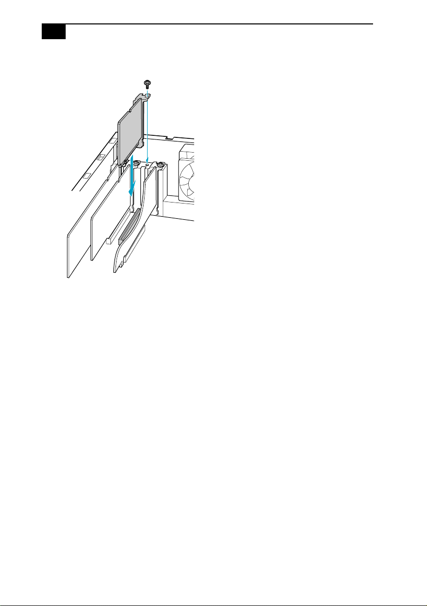
29
Removing the slot cover
❑ Install the add-on card by inserting it into the expansion slot and
secure it with the screw from the expansion slot cover.
! When removing a slot cover, be careful not to damage components on the
system board or add-on cards. You may need to temporarily remove add-on
cards or other components that may be next to the slot cover you want to
remove.
VAIO Digital Studio System Reference Manual
30
Installing an add-on card
1 Attach any internal cables that the card requires. See the instructions
supplied with the add-on card.
2 Replace the side panel. See “Replacing the Side Panel” on page 26.
3 Reconnect all peripheral devices and the power cord, and then turn
on the computer.

Upgrading and Maintaining Components
33
Replacing the Lithium Battery
You may need to replace the lithium battery if your computer consistently
loses the date or time settings after it is turned off. The lithium battery has
a typical life of three years, after which the battery may be too weak to
power the CMOS memory.
1 Reboot your computer by selecting Shut Down... from the Start
menu, and then selecting Restart.
2 If the error message “Error: Check date and time settings” appears
during the reboot sequence, press F2 during the reboot process to
access the BIOS Setup Utility. Otherwise it is not necessary to replace
the battery at this time, and you can skip all remaining steps.
3 Compare all the BIOS options to their default settings (see “CMOS
Setup Options” on page 57). Make a list of all the BIOS options that
are different from their default values. Refer to this list when you
restore the BIOS settings later.
4 Select Exit Discarding Changes from the main menu using the right
arrow key.
5 Press Enter, type Y when prompted to discard changes, then press
Enter to exit the BIOS Setup Utility.
6 Turn off the computer and unplug the power cord.
7 Remove the side panel (see “Removing the Side Panel” on page 24).
! Before opening the system unit, save and close all open files, exit all open
applications, turn off the power to all attached peripheral devices, shut
down the computer, and unplug the power cord.
! Do not handle damaged or leaking batteries.
The lithium battery may explode if mistreated. Do not disassemble it or
dispose of it in fire.
When you remove the lithium battery, all values stored in the CMOS memory
(BIOS setup values and Plug and Play values) may be lost. Although the
computer can hold the charge for a short time while replacing the battery, it
is safer to assume that the settings will be lost. When the values are lost, the
BIOS values revert to their factory-default settings (see “Accessing the BIOS
Setup Utility” on page 16).

Upgrading and Maintaining Components
35
16 If the error message “Error: Check date and time settings.” appears
during the reboot sequence, press F2 during the reboot process to
access the BIOS Setup Utility. If no error message displays, the
computer’s BIOS settings were retained during the battery
replacement and you can skip the remaining steps.
17 Refer to the list you made in step 3 and restore any non-default BIOS
settings (see “CMOS Setup Options” on page 57).
18 Select Exit Saving Changes from the main menu using the right
arrow key.
19 Press Enter, type Y when prompted to discard changes, then press
Enter to exit the BIOS Setup Utility.
The computer’s BIOS settings are now restored.
Upgrading and Maintaining Components
37
Removing a memory module (PCV-RZ series model)
Upgrading and Maintaining Components
39
Installing Memory Modules
Your system supports PC2700 DDR-SDRAM memory modules. The
DDR-DIMM memory modules can be single- or double-sided and
installed in either socket.
1 Choose the size of the memory module and configuration as shown
in the following table. Memory modules can vary in size and speed
between sockets. The minimum memory size is 128 MB. The
maximum memory size is 1.0 GB. The BIOS automatically detects the
type, size and speed of the memory modules.
2 If necessary, remove the memory module you wish to replace (see
“Removing a Memory Module” on page 36).
3 Remove the new memory module(s) from its anti-static package.
Hold the memory module only by its edges to prevent
static-electricity damage.
4 Remove the side panel (see “Removing the Side Panel” on page 24).
5 Remove the power supply (see “Removing the Power Supply
(PCV-RX series models)” on page 49).
*
! Before opening the system unit, save and close all open files, exit all open
applications, turn off the power to all attached peripheral devices, shut
down the computer, and unplug the power cord.
Memory module configurations (MB)
*
* Your computer ships with at least 512 MB of memory and is expandable to 1.0 GB. Your model may
ship with more than 512 MB SDRAM depending on the configuration you purchased.
DIMM1 DIMM2
0, 128, 256, 512 0, 128, 256, 512
✍ Use only PC2700 memory. Your system does not support EDO, buffered
DDR-SDRAM, or PC100/133 SDRAM memory.
! Touch any exposed metal portion of the chassis to discharge static
electricity in your body before handling a memory module.
! Do not remove the Giga Pocket™ card (located in PCI slot No. 3) unless
directed by a service technician. The Giga Pocket card is a fragile
hardware component.
* Applicable to PCV-RX models only.

VAIO Digital Studio System Reference Manual
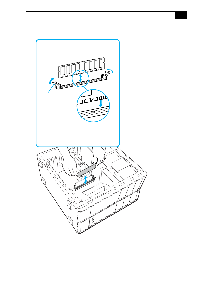
40
6 Align the module over the appropriate socket, noting the location of
pin 1 on the module and pin 1 on the socket.
7 Carefully but firmly insert the edge of the module into the socket.
Press down
here
Handles
Pin 1 side
DDR-DIMM 2
Memory module (DDR-DIMM)
Indicates pin 1
1
11
1
DDR-DIMM 1

Upgrading and Maintaining Components
43
Covering an Open I/O Slot
Slot covers prevent air from escaping through the empty slot. If air
escapes, the components inside the computer cannot be properly cooled.
This may damage some components, especially the main processor,
which generates the most heat.
1 Slide the tip of the slot cover between the chassis and system board.
Covering an open I/O slot (PCV-RX series model)
2 Push the slot cover down until it rests firmly on the lip in the chassis.
All add-on card brackets and slot covers rest on this lip.
3 Replace the slot cover's screw to secure the I/O slot cover.
! Before opening the system unit, save and close all open files, exit all open
applications, turn off the power to all attached peripheral devices, shut
down the computer, and unplug the power cord.
VAIO Digital Studio System Reference Manual
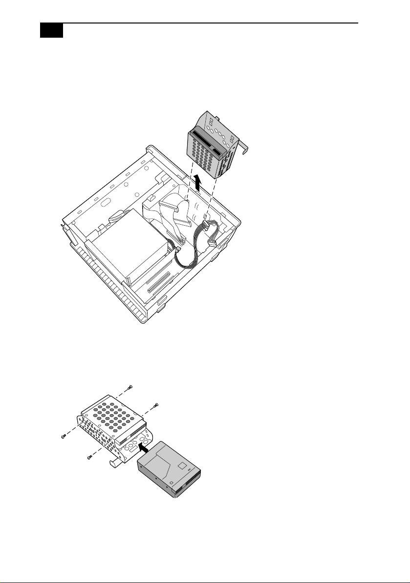
46
6 Slide the drive holder up and out.
Installing an internal hard disk drive (PCV-RX series model)
7 Slide the new drive into the bottom part of the drive holder and align
the holes on each side of the drive holder.
8 Secure the drive to the drive holder using screws in each of the two
holes on each side of the drive holder (screws are provided with the
new drive). Do not overtighten the screws.

Upgrading and Maintaining Components
49
Removing the Power Supply (PCV-RX series
models)
Remove the power supply when you insert a memory module (see
“Removing a Memory Module” on page 36).
1 Remove the screw that secures the power supply to the rear of the
chassis.
2 Pull the tab (A) that latches the power supply to the chassis.
3 Slide the power supply up until the power supply clears the chassis.
Removing the power supply (PCV-RX series model)
4 Rotate the power supply upside down and rest it on top of the chassis
where the hard drive is located.
! Before opening the system unit, save and close all open files, exit all open
applications, turn off the power to all attached peripheral devices, shut
down the computer, and unplug the power cord.
A
51
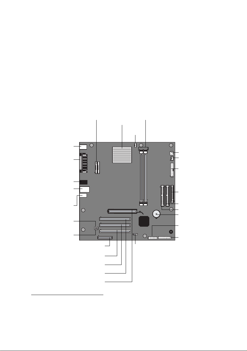
Chapter 4
System Board
This chapter identifies and describes components on the system board.
Processor
CPU Fan
Memory
Power Supply Fan
CPU Power Supply
Power Supply
Secondary IDE
Primary IDE
Floppy Disk
Battery
Front Panel
USB Header
CMOS Clear
Slot No. 3 (PCI)
Slot No. 2 (PCI)
*
Slot No. 1 (CNR)
*
Keyboard, Mouse
Mic In, Line In,
Line Out
i.LINK Header
CD-In
(to front panel)
Aux-In
Slot No. 4 (PCI)
Slot No. 5 (AGP)
(to front panel)
USB5, USB6,
Ethernet
USB3, USB4,
Printer, Monitor,
i.LINK
Header
S/P DIF Out
*
The CNR slot no. 1 and PCI slot no. 2 are located under slot cover no. 1, 2.
Only one expansion slot can be used at a time.

VAIO Digital Studio System Reference Manual
52
Memory Module (DDR-DIMM) Slots
Align pin 1 of the Dual Inline Memory Module (DDR-DIMM) to the small
triangle located on the memory module slot of the system board.
DDR-DIMM1
DDR-DIMM2
Indicates pin 1
Memory module (DDR-DIMM)
1
11
1

57
Chapter 5
CMOS Setup Options
This chapter describes each screen in the Award BIOS Setup Utility (see
“Accessing the BIOS Setup Utility” on page 16).
The Award BIOS setup has five menu items on the menu bar. These are:
❑ Main
❑ Advanced
❑ Power
❑ Boot
❑ Exit
Options that you can change are enclosed in brackets. Text that is not
enclosed in brackets cannot be changed.
A small triangle ( ) indicates that there is a sub-menu with additional
information and options. Press Enter to display the sub-menu. The
information and options in a sub-menu are context-sensitive (they appear
or disappear, depending on which options you select).
The item shown in [brackets] in this guide is the default option. The
option shown in [brackets] on the screen is the option currently set for
your system.
The other available options for each item are shown without brackets
directly below the default option in this guide. The available options are
listed in the order they occur when you press the + key.
Use the left and right arrow keys to choose a menu item. Use the up and
down arrow keys to select an option. Press Enter to display a list of
options, or press the + or - key to cycle through the other options.
If you display the list of options, use the up and down arrow keys to
select an option in the list, then press Enter to choose the selection.
Press Esc to go back to the main menu.

VAIO Digital Studio System Reference Manual
58
Press F10 to save the changes and exit, or press Esc to discard the
changes.
Follow the on-screen prompts for other choices. The bottom of the screen
presents a summary of the keys to use for navigation and control.

CMOS Setup Options
59
Main Screen
System Time [00:00:00]
System Date [01/01/2003]
Primary Master (see
“IDE Sub-Menus”
on page 60)
Primary Slave (see
“IDE Sub-Menus”
on page 60)
Secondary Master (see
“IDE Sub-Menus”
on page 60)
Secondary Slave (see
“IDE Sub-Menus”
on page 60)
Supervisor Password [Disabled]
User Password [Disabled]
Installed Memory See online specifications sheet for details.
BIOS Revision/Version 1002 (depends on model)

CMOS Setup Options
61
Advanced Screen
CPU Speed [1500MHz]
*
Hyper Threading Technology [Enabled]
†
Disabled
I/O Device Configuration (see “I/O Device Configuration Sub-Menu” on page 62)
PCI Configuration (see
“PCI Configuration Sub-Menu”
on page 62)
* CPU Speed may vary, depending on the model purchased.
† Hyper Threading Technology may vary, depending on the model purchased.

VAIO Digital Studio System Reference Manual
64
Boot Screen
1. ATAPI CD-ROM [(displays installed drive)]
Disabled
2. Removable Device [Legacy Floppy]
LS120
ZIP-100
ATAPI MO
USB FDD
Disabled
3. IDE Hard Drive [(displays installed drive)]
Disabled
4. Other Boot Device [Disabled]
INT18 Device (Network)
SCSI Boot Device
Silent Boot [Enabled]
Disabled

VAIO Digital Studio System Reference Manual
66

67
Chapter 6
Miscellaneous Technical
Information
This chapter contains information on the following subjects:
❑ User and Supervisor password
❑ Beep code error messages
❑ PCI configuration status and error messages
❑ DMA channel assignments
❑ System I/O address map
❑ Memory map
❑ IRQ settings
✍ Models equipped with Giga Pocket features may require increased system resources due to
additional hardware.

VAIO Digital Studio System Reference Manual
68
User and Supervisor Passwords
The system allows you to specify up to two passwords (a User password
and a Supervisor password) in the CMOS Setup Utility. The User
password is required; the Supervisor password is optional.
Access to the CMOS Setup Utility depends on which passwords were
previously set, as indicated next.
If you set these passwords... ...the following passwords are required:
User password only User password is required at bootup.
Supervisor password only No password is required at bootup.
Supervisor password is required by most
setup options.
Both passwords User password is required at bootup.
Supervisor password is required by most
setup options.

Miscellaneous Technical Information
69
Beep Code Error Messages
During a normal bootup, a single short beep signifies that the system is
OK. Other beep patterns signify errors. The number of beeps indicates the
specific error that occurred.
If a system error occurs, the Sony Online Support technicians require the
number of beeps your system produces.

Miscellaneous Technical Information
71
Secondary IDE Controller
Resource Conflict
The secondary IDE controller has
requested a resource that is already in use.
Static Device Resource Conflict A non-Plug and Play ISA card has
requested a resource that is already in use.
System Board Device Resource
Conflict
A non-Plug and-Play ISA card has
requested a resource that is already in use.
Message Meaning

VAIO Digital Studio System Reference Manual
72
DMA Channel Assignments
This shows the factory default values. The Windows® operating system
reassigns resources to best meet the needs of a particular configuration.
DMA
Channel
Default
Assignment
Channel 4 Direct memory access controller
Channel 2 Standard floppy disk controller
Miscellaneous Technical Information
75
Memory Map
Resource Device
0x0000-0x9FFFF System board
0xF0000-0xFFFFF System board
0x100000-0x1FFFFFFF System board
0xFEC00000-0xFECFFFFF System board
0xFEE00000-0xFEEFFFFF System board
0xA0000-0xBFFFF PCI bus
0xA0000-0xBFFFF SiS® Accelerated Graphics Port
0xA0000-0xBFFFF NVIDIA® GeForce™ FX 5800 Ultra (Sony)
0xC8000-0xDFFFF PCI bus
0x20000000-0xFEBFFFFF PCI bus
0xE7000000-0xE7FFFFFF SiS Accelerated Graphics Port
0xE7000000-0xE7FFFFFF NVIDIA GeForce FX 5800 Ultra (Sony)
0xEFF00000-0xFEBFFFFF SiS Accelerated Graphics Port
0xE8000000-0xEBFFFFFF SiS Accelerated Graphics Port
0xF0000000-0xF7FFFFFF NVIDIA GeForce FX 5800 Ultra (Sony)
0xFFEE0000-0xFFEFFFFF Motherboard resources
0xFFFE0000-0xFFFFFFFF Motherboard resources
0xE6800000-0xE6800FFF SiS 7001 PCI to USB Open Host Controller
0xE6000000-0xE6000FFF SiS 7001 PCI to USB Open Host Controller
0xE5800000-0xE5800FFF SiS 7001 PCI to USB Open Host Controller
0xE5000000-0xE5000FFF SiS PCI to USB Enhanced Host Controller
0xE4800000-0xE480FFFF Sony Advanced Encoder
Board(KernelStreaming)
0xE4000000-0xE40000FF Realtek® RTL8139/810x Family Fast
Ethernet NIC
0xE3800000-0xE3800FFF NEC OHCI Compliant IEEE 1394 Host
Controller
✍ I/O addresses that may be used by add-on cards are not listed.
77
Chapter 7
Specifications
This chapter describes the technical specifications for your
VAIO Digital Studio™ computer.
Processor
Chipset
AGP Bus
✍ System configuration may vary, depending on the model purchased. Your computer may not
include all of the hardware features discussed in this section.
See online specifications sheet for details.
See online specifications sheet for details.
AGP interface specification, version 2.0 (supports 2x/4x)
One AGP slot

VAIO Digital Studio System Reference Manual
78
PCI Bus
Memory Modules
Memory Configurations
L2 Cache
Graphics
PCI Level 2.2, 33 MHz zero wait state
Three PCI slots - not all slots are available. (See online specifications sheet for
details.)
Installed memory See online specifications sheet for details.
Maximum memory 1.0 GB (512 MB in each socket)
Voltage 2.5 V memory only
Pins 184-pins with gold-plated contacts
Memory type 2.5 V PC2700 DDR-SDRAM unrestricted, unbuffered,
64-bit (Non-ECC) DDR-SDRAM DIMM modules
DIMM1
*
* Your computer ships with at least 512 MB and is expandable to 1.0 GB. DDR-DIMM memory modules
must be 2.5 volts, PC2700, 4-clock between sockets and 64-bit or 42-bit 133 MHz SDRAM.
DIMM2
*
0, 128, 256, 512 0, 128, 256, 512
Installed 512 KB of Advanced Transfer cache
AGP Controller
*
* Supports DDC-1 and DDC-2b standards for Plug and Play displays.
See online specifications sheet for details.
Video memory See online specifications sheet for details.
Resolution (displayed resolution depends on the graphics display you use)
True color (32-bits) Up to 1600 x 1200 at 85 Hz non-interlaced
High color (16-bits) Up to 1600 x 1200 at 100 Hz non-interlaced
256 colors (8-bits) Up to 1600 x 1200 at 100 Hz non-interlaced
Specifications
79
Audio
Communications
Giga Pocket I/O
*
Sound chip See online specifications sheet for details.
Wave synthesis Software synthesis
Sound effects DirectX® software
Audio sampling rate Up to 48 kHz at 16-bits
Rear panel connectors Microphone
Headphones (for stereo headphones)
Line In (from stereo audio source)
Modem
*
* Installed modem may vary, depending on the system configuration purchased.
V.90 compatible data/fax modem
†
† This modem is capable of downloading at 56 Kbps. Your phone service, online service, or Internet Service
Provider may not support this technology or operate at this speed.
Fax 14.4 Kbps maximum
i.LINK® (IEEE 1394)
interface
400 Mbps, OHCI chip set
Ethernet 10BASE-T/100BASE-TX
Rear Audio L/R In jack
Video/S-Video In jack
Video/S-Video Out jack
Audio L/R Out jack
VHF/UHF port
Front Video/S-Video In jack
Audio L/R In jack
* System configuration may vary, depending on the model purchased. See the online specification
sheet for details.

VAIO Digital Studio System Reference Manual
80
I/O and Expansion Slots
Floppy Disk Drive and Controller
Hard Drives and Controller
Speaker DC Out jack One connection for speaker power cable.
Printer port One high-speed bi-directional
Centronics-compatible port with ECP and EPP
modes.
Modem jacks Two RJ-11 jacks (telephone and line).
(See online specifications sheet for details.)
USB 2.0 ports
*
* Universal Serial Bus (USB) 2.0 technology supports high/full/low speeds.
USB1 and USB2 (front panel)
USB3, USB4, USB5, USB6 (rear panel)
(See online specifications sheet for details.)
AGP slot One slot for an AGP card.
PCI slots Not all PCI slots are available for expansion.
(See online specifications sheet for details.)
CNR slot One slot for a CNR modem.
IDE headers Primary and secondary (each supports two IDE
drives)
i.LINK®
(IEEE 1394) ports
One 4-pin port on the front panel
One 6-pin port on the rear panel
Drive Description
Floppy disk controller 82077-compatible (supports up to 2.88 MB)
Floppy disk drive 3.5-inch, 1.44 MB.
Drive Description
EIDE controller Supports up to four EIDE drives (supports PIO
Mode 4 EIDE drives and Ultra DMA/100 Mode
drives)
IDE hard drive
*
* Bus-mastering EIDE driver installed.
See online specifications sheet for details.

VAIO Digital Studio System Reference Manual
82

83
Index
A
address map, system 73
AGP bus specifications 77
audio specifications 79
B
battery - See lithium battery
beep codes
69
BIOS Setup Utility
See CMOS Setup Utility
BIOS setup utility
advanced screen
61
boot screen 64
exit screen 65
main screen 59
options 57
power screen 63
screens 57
BIOS specifications 81
C
chipset specifications 77
CLR CMOS Jumper 55
CMOS - See Also BIOS
CMOS Setup Utility
16
codes, beeps 69
communications, specifications 79
computer
lithium battery
ix
configuring
power management
17
connectors
i.LINK
6
monitor 11
power 53
USB 6
cover, slot 42
covering I/O slot 43
CPU - See processor
D
display, power management 17
disposal of lithium battery ix
DMA channel assignments 72
E
Energy Star iii
error messages
beep codes
69
PCI configuration 70
expansion slots 14
specifications for 80
expansion slots - See slots
F
fax/modem - See modem card
floppy disk drive
specifications
80
front view 2
buttons and switches 4
connectors 5, 6
indicators 5
G
Giga Pocket specifications 79
graphics controller - See graphics
graphics specifications
78
H
hard drive specifications 80

VAIO Digital Studio System Reference Manual
84
I
i.LINK connector 6
I/O address map 73
I/O connectors
i.LINK
13
keyboard and mouse 10
mic, line in, headphones 12
monitor 11
printer port 11
telephone and line 12
USB ports 10
I/O slot covering 43
I/O slot specifications 80
icons, description of 8
IEEE 1394 - See i.LINK
installing
PCI add-on card
31
system memory 39
K
keyboard connector 10
L
L2 cache specifications 78
lithium battery
disposal
ix
safety precautions ix
lithium battery, replacing 33
M
map - See I/O address map and
memory map
memory - See system memory
memory configuration specifications
78
memory module
connector
52
removing 36
specifications 78
messages
error
69
status and error 70
microprocessor - See processor
modem - See communications
monitor - See display
monitor connector
11
mouse connector 10
O
online specifications 1
Optical drive
performance of discs
3, 81
P
panel 26
removing 24
passwords, user and supervisor 68
PCI add-on card
installing
31
PCI bus specifications 78
power connector 53
power management, configuring 17
processor specifications 77, 78
R
RAM - See system memory
rear view
7
I/O connectors 10
icons 8
removing
memory module
36
panel 24
slot cover 42
replacing 26
panel 26
replacing lithium battery 33
resolution - See graphics

VAIO Digital Studio System Reference Manual
86