We bring good things to life.
ARCHITECTS AND ENGINEERS
DESIGN DATA MANUAL
FEATURING THE NEW DRY AIR 25 SERIES
ZONELINE
®
PACKAGED TERMINAL AIR CONDITIONERS

Upfront Filters
All Zoneline units
have removable
upfront filters for
ease of cleaning,
thus assuring high
performance and
longer life.
s
Central Desk Control
All Zoneline units are
compatible with two-
wire central desk ON/
OFF controls, load
shedding systems,
including many
computerized
control systems.
Note: Requires
Optional Interface
Module. (RAKOIM)
s
Zoneline
®
The line of General Electric Zoneline
®
models
has been designed with the focus on efficiency,
quietness and reliability. You can depend on
the same flexible applications that you expect
from previous Zoneline models. To fully
realize all of the benefits of General Electric
Zoneline heating and cooling, proper
installation is necessary.
Please take a moment to read the “important
notice” at the bottom of page 4.
The Zoneline
®
Cooling/Heating Systems are
Ideally Suited for a Variety of Installations
such as . . .
Apartments All living spaces.
Remote Installation Capability
All Zoneline units are compatible
with wall-mounted remote
controls. Note: Requires Optional
Interface Module. (RAKOIM)
s
Freeze Sentinel
TM
All Zoneline units are equipped with Freeze
Sentinel to provide protection against freezing in
unoccupied rooms, regardless of unit setting.
s
See individual sections for application details.
Optional Corrosion Treatment*
Zoneline units can be ordered with special
protective coatings designed to reduce the effects
of corrosive environments. A special treatment is
placed on the outdoor coil and other
components to extend the life of the unit.
*(Standard on Dry Air 25 Models.)
s
Motels and Hotels Guest rooms, offices
and lobbies.
Office Buildings Perimeter offices,
meeting rooms, cafeterias.
Dormitories Student rooms and public
areas.
Schools and Colleges Classrooms,
offices and public areas.
Hospitals, Nursing Homes and Clinics
Patients’ rooms, waiting rooms, and
offices.
Residential Ideal for add-on rooms.
Mobile Homes And portable
classrooms.
Modulars Motels, office buildings,
housing for elderly, student dorms.
3
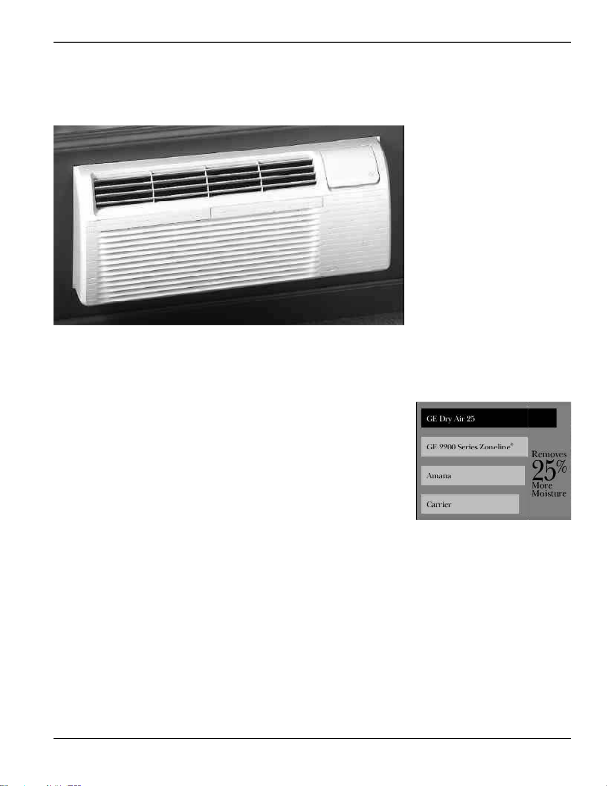
Deluxe Dry Air 25 Models
Cooling With Resistance Heat
• Removes 25% More Moisture than other Zoneline Models, up to 2.7
Additional Gallons Per Day
• Cool and Dry Air in Less Time than Standard Zoneline Models
• Heat Pipe is a Separate Sealed Refrigerant System
- No Mechanical Parts
- No Special Maintenance Required
• Helps Maintain Lower Relative Humidity In Rooms
• Maintains Comfort at Slightly Higher Room Temperatures
- Reduces Operating Costs
- Provides Comfort Without Overcooling
• Corrosion Treatment is Standard
• Best Suited for Humid Climates
• Available in 7000, 9000 and 12000 BTU Sizes
• Two Fan Motors
- Improved Quiet Sound Levels
- High Efficiency
• Mechanical Temperature Limiting
- Reduces Operating Costs
• Freeze Sentinel
TM
- Protects from Damage by Freezing Temperatures
• GE Exclusive Superseal
- Increased Room Comfort
- Energy Savings
• Upfront Filters
- Ease of Cleaning
- Long Lasting Nylon Mesh
• Central Desk Control Compatibility (Requires RAKOIM)
• Remote Thermostat Capability (Requires RAKOIM)
The Deluxe 2200 Series Zonelines Includes The New Dry Air 25
Models Which Remove 25% More Moisture Than Standard
Zoneline Units.
The Newest Innovation from GE...
The Dry Air 25 Models center
around GE’s exclusive use of the
patented Dinh
®
Dehumidifier Heat Pipe
from Heat Pipe Technology, Inc.
This innovative NASA spin-off
technology enables Dry Air 25 to
remove 25% more moisture from the
air than other packaged terminal air
conditioners. This helps maintain
room comfort at a higher room
temperature, reducing operating
costs.
The Dry Air 25 keeps a room cool
and dry, and this is the most
important benefit when it comes to
the occupant of the room - hotel
guests, apartment residents, students
. . . In a hot, humid climate, getting
away from the humidity is just as
important as the heat, and the Dry
Air 25 is the perfect solution.
NOTE: All 2200 Series features mentioned in
this manual include the Dry Air 25 models.
COMPARISON OF DRY AIR 25
IN DEHUMIDIFICATION*
*Based on 12,000 BTU Units.

4
Table of Contents
Dry Air 25 Features .................................................................................................................................................................. 3
Introduction ............................................................................................................................................................................. 5
Outline Drawings (Dimensions)............................................................................................................................................. 6
Zoneline
®
System ..................................................................................................................................................................... 7
Chassis Nomenclature ............................................................................................................................................................. 8
Control Panels & Unit Overview ............................................................................................................................................. 8
Zoneline Series Features .......................................................................................................................................................... 9
Chassis Features and Benefits .......................................................................................................................................... 10-14
Heat Pumps and Energy Savings........................................................................................................................................... 15
3200 Series Heat Pump Operation ........................................................................................................................................ 15
5200 Series Heat Pump Operation ........................................................................................................................................ 16
Optional Interface Module RAKOIM ................................................................................................................................... 16
Central Desk Control ............................................................................................................................................................. 17
Remote Thermostat Control ............................................................................................................................................ 18-20
Wall Case ................................................................................................................................................................................ 21
Sub-Base ................................................................................................................................................................................. 21
Wall Case Installation ....................................................................................................................................................... 22-23
Installation Drawings ........................................................................................................................................................ 24-29
Sub-Base Installation Drawings ........................................................................................................................................ 30-31
Condensate Disposal Systems ................................................................................................................................................ 32
Drain Kit Installation Drawings ....................................................................................................................................... 33-34
Ducted Installations ............................................................................................................................................................... 35
Ducted Installation Drawings ........................................................................................................................................... 36-37
Power Connection Kits For Premium Line (5200 Series) ............................................................................................... 38-39
Power Connection For Deluxe Line (2200 and 3200 Series) .............................................................................................. 40
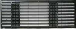
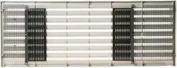
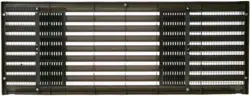
Exterior Grilles ....................................................................................................................................................................... 41
Exterior Architectural Treatments........................................................................................................................................ 41
Application Comments .......................................................................................................................................................... 42
Air Distribution ...................................................................................................................................................................... 42
Cooling Performance Data ................................................................................................................................................... 43
Heat Pump Performance Data .............................................................................................................................................. 43
Latent System Capacity .......................................................................................................................................................... 44
Normal Yearly Operating Data .............................................................................................................................................. 45
Typical Wiring Diagrams ................................................................................................................................................. 46-47
Suggested Bid Form Specifications .................................................................................................................................. 48-51
Chassis Nomenclature ........................................................................................................................................................... 52
Product Specifications ...................................................................................................................................................... 52-53
Power Connection Kits .......................................................................................................................................................... 53
Maximum Connected Loads ............................................................................................................................................ 54-55
Complete Accessory List ........................................................................................................................................................ 56
Replacement Unit .................................................................................................................................................................. 57
New Construction Unit .......................................................................................................................................................... 58
Outdoor Grille Color Samples ..................................................................................................................... Inside Back Cover
Warranty .................................................................................................................................................................. Back Cover
Important Notice
Equipment used as a primary source for heating or cooling is an integral part of the building in
which it is installed. Proper application is essential for satisfactory performance over a wide
range of operating conditions. It is strongly recommended that a professional engineer
determine proper application.
If this unit is a replacement unit, its specifications and performance may differ from those of
the unit it is replacing. For that reason, we again strongly recommend that a professional
engineer determine proper application. See page 42.

8
2200 Series
Dry Air 25
Models
COOLING WITH RESISTANCE HEAT
High Efficiency (EER 9.6 to 11.6) - Standard Microprocessor
Controls, Fan cycle switch, Fan only setting and Concealed
manual vent control. All models are equipped with Freeze
Sentinel
TM
, mechanical temperature limiting and low
voltage (24v) DC power supply for 2 wire Central Desk
Control* systems. Units are easily convertible for use with
remote thermostat control.*
3200 Series
COOLING, HEAT PUMP
WITH RESISTANCE HEAT BACKUP
High Efficiency (EER 9.6 to 11.6; COP 3.1 to 3.5) Standard
Microprocessor Controlled Heat Pump models. 3200 Series
includes all 2200 Series features, plus heat pump operation.
Heat Pump operates to outdoor temperatures as low as 25°F.
(9°F outdoor coil temp) depending upon outdoor humidity
conditions and/or the balance point of the system. The unit
automatically switches to Resistance Heat if heat pump is
unable to maintain room conditions. Utilizes passive air defrost
system. Resumes Heat Pump operation when
outdoor coil reaches 36°F. “Internal Condensate Removal”
(ICR) system is available as an option. ICR minimizes the need
for expensive internal or external drain systems to remove
condensate generated during heat pump operation.
5200 Series
COOLING, HEAT PUMP
WITH RESISTANCE HEAT BACKUP
Full Featured, High Efficiency (EER 10.0 to 12.0; COP 3.1 to
3.5), Highly Featured Microprocessor Controlled Heat
Pumps. 5200 Series features include Freeze Sentinel
TM
,
Automatic Fan Speed Control, Staged Heating, Universal
Heater, UPC Power Connection, and 7-step Electronic
Temperature Limiting. All 5200 Series models are adaptable
to 2 wire Central Desk Control* systems. Units are also easily
convertible for use with remote thermostat control.* The
Heat Pump operates to outdoor temperatures as low as 25°F.
After a low outdoor temperature (less than 25°F) the unit
resumes heat pump operation when outdoor air
temperature reaches 32°F.
If heat pump is unable to maintain selected room conditions
when outdoor temperatures are below 46°F., the unit will
automatically phase-in partial resistance heat simultaneously
with heat pump operation before switchover to full resistance
heat. 5200 Series features an active demand reverse cycle
defrost system. “Internal Condensate Removal” (ICR)
system is available as an option. ICR minimizes the need for
expensive internal or external drain systems to remove
condensate generated during heat pump operation.
*(Requires “Optional Interface Module” (RAKOIM) for Central
Desk Control or Remote Thermostat Control operation.)
Zoneline
®
Chassis Nomenclature
The Zoneline chassis is identified by a model number defining the type of unit, cooling capacity, electrical information and optional features
included on the unit. When specifying or ordering the Zoneline chassis the use of this nomenclature will assure receiving the correct unit.
Example
A Z 5 2 H 1 2 D A D
Zoneline
®
Packaged Terminal Chassis
Chassis Series
22 - Deluxe Line Cool/Electric Heat
32 - Deluxe Line Heat Pump
52 - Premium Line Heat Pump
Unit Type
E - Cooling with Electric Resistance Heat
H - Heat Pump with Electric Resistance Heat
Special Features
B - Base Unit
C - Corrosion Treated
D - Internal Condensate Removal
(ICR) System (Heat Pump Models Only)
P - Dry Air 25
5200 Universal Power Connection
(see Premium Series Models - see page 53)
2200, Dry Air 25 & 3200 Numeric Designator
of Heater Size
(see Deluxe Series Models - see Page 52)
Voltage/Frequency
D - 230/208 Volt 60 Hz E - 265 Volt 60 Hz
Nominal Cooling Capacity
07 - 7,000 BTUH Cooling 12 - 12,000 BTUH Cooling
09 - 9,000 BTUH Cooling 15 - 15,000 BTUH Cooling

9
Zoneline
®
Features Model Series
AZ AZ AZ
2200 3200 5200
Enhanced Dehumidification - Dry Air 25 Optional N/A N/A
Cooling EER Range (230 Volts/265 Volts) 9.6 - 11.6 9.6 - 11.6 10.0 - 12.0
Heating COP Range (230 Volts/265 Volts) N/A 3.1 - 3.5 3.1 - 3.5
Heat Source - Electric Resistance Heat Pages 52, 53 — —
Heat Source - Heat Pump With — Std. Pages —
Backup Resistance Heat 52, 53
Heat Source - Heat Pump With Selectable
Full Time or On Demand Simultaneous/ — —
Supplemental Resistance Heat
Quick Heat Recovery — Std. - Page 14 Std. - Page 14
Heat Pump Defrost system — Passive Reverse Cycle
Fan Motors - Permanently Lubricated 2 2 2
Standard Microprocessor Controls Standard Standard —
Highly Featured Microprocessor Controls — — Standard
Rotary Compressor Standard Standard Standard
Automatic Compressor Restart Delay Standard Standard Standard
Corrosion Treated
(Not Available in 5KW Heater)
Optional Optional —
(Not Available in 265V, 2KW Heater)
Power Connection** Included Included UPC*
Universal Heater — — Standard
Reversible Indoor Air Louvers Air Discharge Air Discharge Air Discharge
Angles: 40°/50° Angles: 40°/50° Angles: 40°/50°
Fan Cycle Switch Standard Standard Standard
Indoor Fan Speed Selections - Hi/Low Standard Standard Standard
Automatic Indoor Fan Speed — — Standard
2 Speed Outdoor Fan Standard Standard Standard
Fan Only Setting Standard Standard Standard
Up-Front Filters Standard Standard Standard
Concealed Manual Vent Control Standard Standard Standard
Rotary Control Knobs Standard Standard —
Touch Controls (Tactile Controls) — — Standard
Electronic Temperature Selection — — Standard
(Slews Up & Down) with Digital Display
Staged Heating — — Standard
Freeze Sentinel
TM
Standard Standard Standard
Automatic Emergency Heat — Standard Standard
Electric Resistance Heat Lock-Out (above 46°F) — — Standard
Temperature Limiting Mechanical Mechanical 7-Step
Electronic
Remote Control Capability With Requires RAKOIM Requires RAKOIM Requires RAKOIM
Wall Mounted Thermostat Page 16 Page 16 Page 16
Central Desk Control Capabilitys Requires RAKOIM Requires RAKOIM Requires RAKOIM
With Load Shedding Option Page 16 Page 16 Page 16
Ducted Installation Capability RAK6052 RAK6052 —
Unit Diagnostics — — Standard
Service Indicator — — Temp Display Blinks
Internal Condensate Removal (ICR) N/A Optional Optional
Factory Installed Option.
Cannot be used in Corrosion Areas.
*UPC - Universal Power Cord Connection (See pages 38, 39 and 53)
**265 volt product. MUST be direct connected to meet National Electrical Code and all local codes.
Std. Pages
16, 53

10
Chassis Features and Benefits
• Consistent Physical Dimension
Fits all existing GE Zoneline wall cases (see page 21)
The GE Zoneline was first introduced into the marketplace
in 1961. Since that time, efficiencies and features have been
greatly improved. In spite of these improvements, GE
recognizes that some features should stay the same. That’s
why any recently-manufactured Zoneline chassis can be
installed in any Zoneline wall case, regardless of age. The
original Zoneline wall case was 42" wide by 16" high, the
same dimension of the wall case today, enabling a new
Zoneline to be installed in an existing 42" by 16" wall case
without the need for extensive modifications. Note: Existing
outdoor grille may need to be replaced or modified. (see
page 41)
• Controls Conveniently Located, Easy to
Operate
Reduces uncertainty of operation for room occupant
(see page 8)
Zoneline controls are mounted on the top of the unit,
angled for better visibility and access. The controls are
under a door for appearance enhancement. The 2200 Series
and the 3200 Series have rotary controls for temperature
and operation selection. The 5200 Series units have Touch
Pad controls. An optional locking control door, RAK8022 is
available.
• Universal Heater - Premium Models
Resistance heat output of unit can be matched to the heating
demands of the particular area (see pages 38, 39 and 53)
Often, the choice of a Zoneline heater is influenced by the
location of the room it is intended to heat. For instance, the
end room in a wing or the corner rooms on top floors will
have a higher heat loss than interior rooms having only one
wall exposed to the outdoors. These higher heating
demands are often compromised for the sake of equipment
consistency. In many instances, all rooms are sized higher to
accommodate the minority of the rooms having the higher
heat loads. Naturally, such sizing policies result in increased
total connected current load, and quite often, higher overall
energy costs.
In response to this customer need, each Premium Model is
equipped with three built-in heaters and, when connected
with the proper Universal Power Connection Kit (UPC), can
be closely matched to the heating requirements and circuit
ampacity of a specific room. In addition, this feature allows
maintenance personnel to interchange units in rooms
having different heating requirements.
• Discreet Heater - Deluxe Models
Resistance heat output of unit can be matched to the heating
demands of the particular area (see pages 38, 39 and 53)
Deluxe Models offer cost-conscious customers factory-
installed discreet heaters. The ninth character in the Deluxe
Line model number represents the specific wattage of the
heater. A Deluxe Model chassis may be ordered with a
custom resistance heater in any one of the following
KW ratings:
230/208 Volts: 2.55/2.09 KW; 3.45/2.82 KW;
5.00*/4.09 KW
265 Volts: 2.00 KW; 3.00 KW; 4.00 KW; 5.00 KW*
• Premium Models - Universal Heater and
Power Cord
UPC Heater KW- Premium Models
230/208 volt 15 amp RAK3152 2.55/2.09 KW
20 amp RAK3202 3.45/2.82 KW
30 amp RAK3302 5.00*/4.09 KW
265 volt 15 amp RAK5152 1.7 KW
15 amp RAK5172 3.0 KW
20 amp RAK5202 3.7 KW
30 amp RAK5302 5.0 KW*
• Reversible Discharge Louver
Enables discharge air flow to be changed to maximize air
distribution and comfort (see page 42)
Reversible louver section on all units.
The discharge louver section comes from the factory set to
exhaust air into the room at an angle of 50° off vertical. The
louver section may be reversed to provide a discharge angle
of 40° off vertical with the simple removal of seven screws,
rotating the louver section end to end, and reinserting the
screws. The screws are located on the inside of the room
cabinet.
• Fan Cycle Switch
Allows indoor fan to be set to run continuously or cycle on and off
with compressor and heater
Setting the fan to cycle off and on with the compressor or
heater results in some energy savings when the fan is not
operating. The amount of energy savings will vary
depending upon many factors.
2200 & 3200 Series: The room cabinet must be removed to
gain access to the fan cycle switch. The switch is set in the
DOWN/OFF position at the factory to provide continuous
fan operation in the cool and heat modes. Leaving the
switch in the continuous setting allows circulation of room
air and will result in a more uniform temperature
throughout the room.
The fan switch on the Deluxe Models is located on the
Auxiliary Control Panel. It is switch number two. Setting the
switch in the UP/ON position will cause the fan to cycle on
and off with the compressor or resistance heater. In humid
climates, operating the unit in “FAN CYCLE” may result in
better dehumidification.
5200 Premium Model: The fan cycle switch is located
behind the room cabinet. The switch is set in the DOWN/
OFF position at the factory to provide continuous indoor fan
operation in the cool and heat modes. Leaving the switch in
the DOWN/OFF setting allows continuous circulation of
room air and will result in a more uniform temperature
throughout the room. In humid climates, operating the unit
in “FAN CYCLE” may result in better dehumidification.
The fan switch on the Premium Models is located on the
Auxiliary Control Panel. It is switch number nine. Setting
the switch in the UP/ON position will cause the fan to cycle
on and off with the compressor or resistance heater.
*NOTE: 5.0 KW heaters not available on 7,100 BTUH units.
14
Chassis Features and Benefits
• Unit Diagnostics
Switch on auxiliary control panel cycles unit’s components to help
detect malfunction
Unit Diagnostics is standard on the Zoneline 5200 Series.
When the Unit Diagnosis switch, located on the auxiliary
control panel, is turned to the “ON/UP” position, the unit
cycles through the operation of various components. The
operation of the main heater, supplemental heater, indoor
fan motor (both high and low speeds), and the compressor
are checked.
The reversing valve is also cycled through the cooling and
heating modes. The Unit Diagnostics feature helps a
servicer identify a malfunctioning component thus reducing
service call time. During the Diagnostic Cycle a “d” will be
displayed in the temperature display.
• Quick Heat Recovery (5200 and 3200 Series)
Provides faster room comfort conditions in heating operation
As the name implies, Quick Heat Recovery activates
whenever the heating selection has been initialized. This
feature provides electric resistance heat whenever the unit is
turned on in a heating mode or switched from any other
mode to heating. Its purpose is to quickly bring a room to
the desired temperature by using electric resistance heaters.
This feature minimizes any concerns a room occupant
might raise about the discharge air temperature of a heat
pump and the time it might take to bring the room up to
temperature. Quick Heat Recovery is functional when
connected to a Central Desk Control system.
• Electric Resistance Heat Lock-Out
(5200 Series Only)
Saves energy during milder temperature conditions
The electric resistance heaters are disabled on the 5200
Series whenever the outdoor temperature is above 46°F. This
feature decreases operational costs by automatically
maintaining energy-efficient heat pump operation during
conducive weather conditions. However, The Quick Heat
Recovery Feature (described above) is still operational.
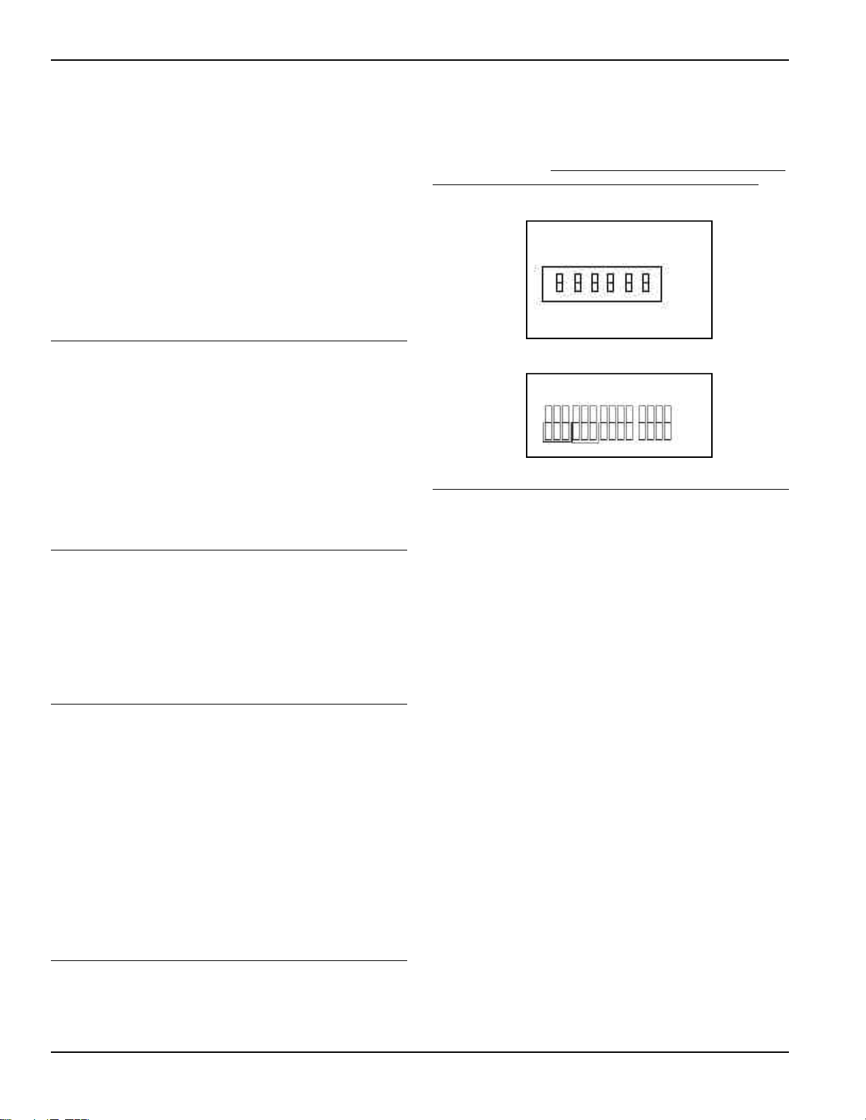
• Load Shedding Option (RAKOIM required)
Provides installation flexibility
Load shedding may be accomplished on any Zoneline
connected to an Energy Management Control System.
Premium Models: The Load Shedding dip switch (switch
“C” (12th from the left), located on the auxiliary control
panel) must be set in the ON/UP position. Deluxe Models:
Load Shedding may also be achieved by setting switch (5th
from the left), located on the auxiliary control panel) to the
ON/UP position.
Load Shedding allows building management to gain control
of the Zoneline’s compressor and heater without affecting
fan operation. Under these circumstances, the fan will
operate whenever the Zoneline’s thermostat closes. Normal
operation is restored when the Energy Management Control
System relinquishes control.
• Auxiliary Controls
The switches on the Zoneline models can be set to provide
operational control to the unit that is not available to the
tenant of the room. It is the owners responsibility to position
these switches to provide the unit operation they desire.
• 2200 Series Enhanced Dehumidification
The Newest Innovation from GE...the Dry Air 25
The Dry Air 25 Models center around GE’s exclusive use of
the patented Dinh
®
Dehumidifier Heat Pipe from Heat Pipe
Technology, Inc. This innovative NASA spin-off technology
enables the Dry Air 25 to remove 25% more moisture from
the air than other packaged terminal air conditioners.
The Dry Air 25 system, Heat Pipe, is a hermetically sealed
heat transfer surface that is saddle-bagged around the
indoor coil (evaporator) of the Zoneline. This coil
arrangement will transfer heat from one coil to another
without power consumption. This assembly uses R-22 as the
refrigerant and is isolated from the regular Zoneline
refrigerant circuit.
As warm humid air is pulled through the pre-cool section of
the Heat Pipe, the heat removed from the air is absorbed by
the refrigerant, causing the refrigerant to boil. As the pre-
cooled air passes through the Zoneline evaporator, the air is
further cooled (colder than it would be normally), removing
25% more moisture than other packaged terminal units.
As the cold air passes through the re-heat section of the Heat
Pipe, the refrigerant condenses and the liquid flows back to
the pre-cool section to be re-heated again. The air
discharged into the room by this process is much drier,
creating a more comfortable room condition.
The Dry Air 25 is perfect for high humidity climates.
Available on 7000, 9000 and 12000 BTU models.
2200/3200 Series
5200 Series
1 2 3 4 5 6
UP
DOWN
1 2 3 4 5 6 7 8 9 A BCDE
UP
DOWN

15
Heat Pumps and Energy Savings
• GE Zoneline Heat Pumps are designed to provide cost
efficient heat pump operation while monitoring room
conditions to maintain comfort.
The units employ a logic system monitoring both outdoor
and indoor temperatures to determine the heat source, thus
increasing energy savings by operating longer in the heat
pump mode.
Heat pumps save energy and cost less to operate than units
with electric resistance heaters as the only heat source. Just
as the EER of an air conditioner is an indication of the
efficiency of the unit, COP (Coefficient of Performance) is
the indication of the efficiency of the heat pump. This
relative efficiency of a heat pump compares the unit to
electric resistance heat. If a unit has a COP of 3.0, it means
the unit will produce three times as much heat at rating
conditions for the same electrical input wattage as an
electric resistance heater.
The compressor is used in heat pump operation just as in
air conditioning operation. In heat pump operation, the hot
refrigerant gas is directed to the indoor coil rather than to
the outdoor coil. Room air that circulates over the indoor
coil gains heat from the coil rather than losing heat to the
coil as during cooling operation.
As the outdoor temperature falls, the heat pump is able to
extract less heat from the outdoor air to raise the
temperature of the indoor air. For this reason all packaged
terminal heat pumps also have electric resistance heaters as
backup to heat pump operation. At some point the heat
pump is unable to provide sufficient heat to adequately
warm the room. Many Packaged Terminal Heat Pumps
cease heat pump operation and change to more expensive
resistance heat at some pre-determined outdoor
temperature to compensate for the inability of the heat
pump to maintain room temperature. This point, called the
“switchover point”, is usually at an outdoor temperature
where savings from heat pump operation may still be
realized, if the unit is designed to maintain room comfort at
the lower outdoor temperatures.
Balance Point
An important consideration of the selection of a heat pump
unit is the “balance point” of the installation. Virtually every
room is unique - with different insulation - different sizes and
types of windows - different types of construction - different
directional exposures. All of these variables, as well as
geographical location, must be considered in order to
determine the balance point, the point at which the heat
pump is unable to produce enough heat to compensate for
the heat loss of the room or area being heated. For these
reasons a consulting engineer should be engaged to
calculate the heat loss and specify the heat pump unit
required.
GE offers two series of Heat Pump units - the 3200 Series
with Standard Microprocessor controls and the 5200 Series
with Highly Featured microprocessor controls - and both
Series utilize multi-stage thermostats to react to the indoor
temperature as well as the outdoor temperature in
determining the heat source to provide comfortable room
conditions and energy savings. This determination of the
heat source based on the indoor temperature helps provide a
more comfortable room.
• Heat Pump Operation — Zoneline 3200 Series
Switchover to resistance heat is determined by indoor temperature
differential and outdoor coil temperature
The Zoneline 3200 Series heat pumps are Standard
Microprocessor controlled units. A solid state thermostat
control is used to measure the room temperature and
compare it to the temperature selected with the “TEMP”
control knob. A temperature sensor is in contact with the
outdoor coil to monitor the outdoor coil temperature
during heat pump operation.
The switchover point of the 3200 Series heat pump is
determined by the outdoor coil temperature or the indoor
air temperature. When the outdoor coil temperature is
above 9°F. (which corresponds to approximately 25°F.
outdoor air temperature), the unit attempts to provide
sufficient heat through heat pump operation to satisfy the
selected temperature setting.
A two-stage thermostat monitors the indoor room
temperature and determines if the heat pump output is
adequate to maintain comfort conditions. As long as the
heat pump output maintains the room temperature within
2.7°F of the set point, the unit will operate in the heat pump
mode. If the room temperature continues to decline with
the heat pump operating, heat pump operation will
terminate and the unit will switch over to electric resistance
heat to warm the room. This heat source logic allows the
heat pump to operate to lower outdoor temperatures,
increasing the savings from heat pump operation, while
providing the ability to use resistance heat only when
necessary. The heat pump and the electric resistance heaters
never operate simultaneously on the Zoneline 3200 Series
Units.
Heat pump defrost - 3200 Series
If the outdoor coil drops below 9°F. (which corresponds to
approximately 25°F. outdoor air temperature), the unit
employs a passive defrost system. A “passive defrost system”
prevents heat pump operation until outdoor temperatures
rise sufficiently to enable economical heat pump operation
to resume. During the defrost mode, the indoor temperature
is maintained by the electric resistance heaters. The defrost
cycle terminates when the outdoor coil temperature rises
above 36°F., at which point the two-stage thermostat will
allow the unit to return to economical heat pump operation.
Heat pump condensate
See page 32 for information on heat pump condensate. The
Zoneline 3200 Series heat pumps may be ordered with a
factory installed Internal Condensate Removal (ICR) system
to minimize the amount of condensate water draining from
the unit during heat pump operation.

16
Heat Pumps and Energy Savings
• Heat Pump Operation — Zoneline 5200 Series
Heat sources: Heat pump, heat pump and simultaneous electric
resistance heat, or electric resistance heat
The Zoneline 5200 Series heat pumps employ a highly
featured microprocessor control system interfaced with
thermistors to accurately measure indoor air temperature,
outdoor air temperature, indoor coil temperature, and
outdoor coil temperature. This system allows the
microprocessor to precisely and predictably react to
changing conditions in order to provide a very advanced
Packaged Terminal Heat Pump operating system.
The Zoneline 5200 series is designed to help insure a
comfortable room. When “HEAT” is selected, the unit will
determine if the room air is warm enough to satisfy the
thermostat setting. If the temperature at the unit sensor is
below the desired temperature, the electric resistance heater
will be utilized to warm the room to the point where the
thermostat is satisfied. This feature is designed to allow the
temperature of an unoccupied room to be maintained at an
energy saving level without inconveniencing the room
occupant. Once the thermostat has been satisfied, the
resistance heater will turn off and the heat pump will
operate as shown in Zoneline 5200 Series Heat Source Logic
chart when the thermostat calls for heat again. The unit will
operate in this manner even if connected to a Central Desk
Control.
The “Temperature Boost” option, selected by a hidden dip
switch #8, utilizes the supplemental simultaneous heater
with heat pump operation when the outdoor temperature is
below 46°F. regardless of the indoor air temperature. The
chart above indicates the heat source of the Zoneline 5200
series heat pump under various indoor and outdoor
conditions. The unit is designed to provide heat pump
savings without sacrificing room comfort.
The Quick Heat Recovery feature is not affected by the
Zoneline 5200 Series Heat Source Logic shown in the chart
above. For more information about the Quick Heat
Recovery Feature, see page 14. The full heat output of the
resistance heater is dependent upon circuit amperage and
the power connection kit used. See pages 38 and 39 for
information on the power connection kits and available
heater capacities.
Heat pump defrost - 5200 Series
The Zoneline 5200 Series has a reverse cycle demand defrost
system to extend heat pump operation and increase savings
from the extended operation. The microprocessor
determines the need for defrosting by criteria based on
continuous compressor running time, outdoor air
temperature, outdoor coil temperature, and the rate of
temperature change of the outdoor coil. When defrosting is
required, the unit reverses the flow of refrigerant to direct the
hot gas into the outdoor coil to melt the frost build-up.
Before and after actual reverse cycle defrosting, the unit shuts
off the compressor to allow the refrigerant pressures to
equalize throughout the system. This eliminates the
possibility of a loud reversing noise. During these periods of
pressure equalization, the full resistance heat capacity of the
unit is activated to help insure room comfort conditions
during the defrost cycle. The defrost cycle termination
requires a minimum of 2 minutes and a maximum of 9
minutes or an outdoor coil temperature of 68°F.
Heat pump condensate See page 32 for information on heat
pump condensate. The Zoneline 5200 Series heat pump may
be ordered with a factory installed Internal Condensate
Removal (ICR) system to minimize the amount of
condensate water draining from the unit during heat pump
operation.
Optional Interface Module —
RAKOIM
The RAKOIM is required if a unit is to be installed with a
Central Desk Control or Remote Thermostat.
The RAKOIM is installed under the control box. There are
channels to contain the RAKOIM and screws are provided to
secure it in place. There is a short wire harness on the
RAKOIM that is plugged into the mating receptacle on the
front of the control box just below the dip switches. There are
screw terminals on the front of the RAKOIM for field wiring.
Follow the instructions included with the RAKOIM when
installing this accessory.
Zoneline 5200 Series Heat Source Logic
ROOM
TEMPERATURE
VS. THERMOSTAT
SET POINT
Less Than 1.8°F.
Below
1.8°F to 2.7°F.
Below
More than 2.7°F.
Below
Outdoor Temperature
Above 46°F.
Heat Pump
Heat Pump
Heat Pump
Between 46°F.
and 25°F.
Heat Pump*
Heat Pump +
Supplemental
Heater
Full Resistance
Heat
Below 25°F.
Full Resistance
Heat
Full Resistance
Heat
Full Resistance
Heat
*If the “Temperature Boost” switch (dip switch #8)is in the “ON”
position the supplemental simultaneous heater will be used with heat
pump operation. Simultaneous supplemental heater: 1.0 KW @ 230 V;
0.8 KW @ 208 V; 1.7 KW @ 265 V
*These terminals are not used for the Cooling/Electric Heat 2200
series models (Thermostat RAK163)
Four (4) conductors are required.
All of the terminals are required for the Heat Pump models,
3200 and 5200 Series (Thermostat RAK147)
Six (6) conductors are required.
The two terminals (A and B) are for Central Desk Control.
Remote RAKOIM
Thermostat Terminal
Terminal ID Identification
R R – 24V DC
G G – Fan
* B * B – Sol
Y Y – Cmp
W W – Htr
* C * C – Gnd
RAKOIM
TERM. STRIP
R
24V DC
G
B
*
Y
W
C
*
B
A
24 VT
CDC
A
CDC
B
24V
DC
FAN
SOL
CMP
HTR
GND

17
Central Desk Control -
Optional Interface Module (RAKOIM) is
required
Some installations may want to govern the ability of the unit
to operate from a control device remote to the unit or even
remote to the room in which the unit is located. The general
term given to systems such as this is Central Desk Control.
The most common installation of this type of system is a
switch mounted at the registration desk and, upon guest
check-in, a button is pushed or a switch is moved to allow
the air conditioner to operate. Likewise, when the guest
checks out the device is put into the “OFF” position so the
unit will not operate while the room is vacant. It is not
necessary that the controlling device be located at a central
desk to employ a device that will control the unit operation.
For instance, in some resort areas devices are connected to
sliding glass doors and opening the door causes a contact to
close, signalling the air conditioner to turn off. This
prevents energy being wasted by operating the air
conditioner when warm humid air is entering the room.
Some systems operate by motion sensors or heat sensing
detectors mounted in the room. These types of systems
determine occupant presence in the room and allow the
unit to operate; if no one is in the room the device signals
the air conditioner to turn off.
Zoneline models offer Load Shedding capabilities on units
connected to Central Desk Control Systems. For more
information on the Models’ Load Shedding Feature, see
page 14.
There are a wide variety of devices available, each with its
own benefits and constraints. While GE does not offer
components that are external to the unit for a Central Desk
Control (CDC) system, GE Zonelines are compatible with
most CDC and Energy Management systems. No external
power source is required to operate this system. The unit
provides a 24 volts DC circuit that powers the Central Desk
Control system.
All Zoneline 2200, 3200, and 5200 Series units can have the
Optional Interface Module (RAKOIM) field installed to
provide a CDC interface that permits the unit to be
connected to most of the energy management systems on the
market. The devices connected to the Zoneline units require
no power supply or transformer external to the unit.
See page 16 RAKOIM for field wiring.
Important CDC Comments (all series applicable)
1) When the switching device closes the circuit of the
CDC conductors, the unit operation stops.
2) Do not
use a common buss (at the unit or at the switch
panel) in the wiring. Both wires comprising the circuit
must connect to the unit’s (RAKOIM) and to the
controlling switch. Running one wire from one unit
to another unit - “common bussing” - may damage
internal components or cause erratic operation of
the system.
3) A 24 volt transformer is contained within the
Zoneline. No external voltage should be applied to
the unit through the CDC terminals. (Voltage on the
CDC conductors is 24 volts DC.)
4) Recommended wire size must be followed as a
minimum requirement.
Freeze Sentinel
TM
remains operational when the unit is
connected to a CDC system. Even if the unit is turned “OFF”
at the central location, if the sensor at the unit detects the
low temperature, the electric resistance heaters and the fan
will automatically turn on.
Connecting the Zoneline to a CDC system does not eliminate
the ability to connect the unit to a remote thermostat. Once
the circuit is “opened”, and control of the unit removed
from the CDC system, the selected controls - either the unit
mounted control or the remote thermostat - govern the
operation of the unit.
CDC Terminal Location and Typical Wiring
Auxiliary Control Panels With Cover Removed
Wire Size #AWG
#22
#20
#18
#16
Maximum Allowable Length
600 Ft.
900 Ft.
1500 Ft.
2000 Ft.
Example of Common Bussing
NOT PERMITTED
INCORRECT Common Bussing
Normally Open
Switch -
Unit Operational
Typical Wiring
(All Wiring Shown Is Field Supplied)

18
RAK163A1
Remote Thermostat Control
Optional Interface Module (RAKOIM) is
required
In some installations, control of the
operation of the unit at a location
remote to the unit itself is desired. A
unit mounted high in the wall, or over a
transom, for instance, where the unit
mounted controls are inaccessible, can
be connected to a wall mounted
thermostat. The unit is connected to the
thermostat by low voltage wiring which
permits the operation of the unit to be
selected and the temperature to be
sensed at the thermostat. Other
installations may use remote thermostat
control for design or performance
enhancement.
All Zoneline 2200, 3200 and 5200 Series units are adaptable
to the Optional Interface Module (RAKOIM) kit to be
controlled with a Class 2 remote low voltage thermostat. The
only additional field supplied components are the remote
thermostat and wiring necessary to
connect it.
The controls on the unit are not functional when the remote
control function is used.
Resistance Heat Models
The Zoneline 2200 resistance heat units may be connected
to a single stage manual switchover thermostat designed for
use with cooling electric heat systems. A thermostat, model
RAK163, is available from GE for use with these units. The
control voltage on the remote control conductors is 24 volts
DC. The DC voltage may not be compatible with some solid
state remote control thermostats.
As shipped, the 2200 Series units operate in HIGH fan
speed when connected to a remote thermostat. Low fan
speed can be attained by positioning the dip switch #4
(low fan) to the ON/UP position.
Freeze Sentinel
TM
remains operational if the unit is
connected to a remote thermostat. The unit may be
connected to a Central Desk Control (CDC) system and
controlled with a remote thermostat when the CDC system
has the unit in an operational status. See pages 16 and 17
for additional information on the CDC system.
Field Wiring Terminal
R – 24V DC
G – Fan
Y – Cmp
W – Htr
* These terminals not used for the 2200
Follow the instructions included with the RAKOIM when
installing this accessory.
RAKOIM
TERM. STRIP
R
24V DC
G
B
*
Y
W
C
*
B
A
24 VT
CDC
A
CDC
B
24V
DC
FAN
SOL
CMP
HTR
GND
RAK 806 Universal Control Cover Label
When a Zoneline unit is using a remote thermostat control,
the RAK806 Universal Control Cover Label is
recommended. The label adheres over the control panel
directing the user to the wall thermostat for operation of the
Zoneline unit.
19
Remote Thermostat Control
Heat Pump Models
The Zoneline 3200 and
5200 Series heat pump
units may be connected to a
one stage cooling/two stage
heating manual switchover
thermostat designed for use
with heat pump systems. A
thermostat, model RAK147, is available from GE for use
with these units. The control voltage on the remote control
conductors is 24 volts DC. This DC voltage may not be
compatible with some solid state remote control
thermostats.
The 3200 and 5200 Series units use the Optional Interface
Module (RAKOIM), purchased separately. The wiring
connections from the thermostat are made to the color
coded conductors on the socket wire kits. To ensure proper
operation, be sure no wiring is exposed that may come in
contact with the chassis. (A wiring diagram is packaged with
each chassis.)
The 6 remote thermostat conductors for 3200 Series and
5200 Series units are connected to the RAKOIM low voltage
terminal board as shown below. The Class 2 Mode Switch
(dip switch #10 on the auxiliary control board) must be set
to the ON/UP mode to enable remote thermostat control.
Note: When the unit is operated with a remote thermostat,
the unit operates on high fan speed.
Low fan speed can be attained if (3200 #4 dip switch)
(5200 #11 dip switch) the “low fan” dip switch is positioned
to “ON/UP”.
Reverse cycle defrost on the 5200 series remain operable
when remote thermostat is used.
Freeze Sentinel
TM
remains operational if the unit is
connected to a remote thermostat. The unit may be
connected to a Central Desk Control (CDC) system and
controlled with a remote thermostat when the CDC system
has the unit in an operational status. (See pages 16 & 17 for
additional information on the CDC system.)
Heat pump operation on a 3200 Series and 5200 Series unit
connected to a remote thermostat is the same as the
operation of the unit without the remote thermostat with
the following exceptions:
The Staged Heating feature (See page 16) on the 5200
Series units does not function with remote thermostat
control. Staged Heating is dependent upon the temperature
sensing ability of the thermistor on the unit, which is
overridden by the remote thermostat. The unit will operate
on heat pump as long as the room temperature is less than
3.6°F. below the thermostat set point and will change to full
resistance heat if the difference is more than 3.6°F. The
temperature differential between heat pump and resistance
heat operation is determined by the remote thermostat
rather than the thermistor on the unit. Even when
connected to a remote thermostat, electric resistance heat is
locked-out when outdoor temperature is above 46°F. (See
Page 16 for the heat pump operating logic of the 5200 Series
units.) Only Electric Heat is available below 46°F. outdoor
temperature if the Temperature Boost switch (dip switch
#8) is set to the ON/UP position.
RAK147A1
LOW VOLTAGE
CONDUCTORS
(field supplied)
4
up to 60 ft AWG20
up to 66 ft AWG18
6
up to 60 ft AWG20
up to 66 ft AWG18
ZONELINE
SERIES
2200
3200 and
5200
ALL
THERMOSTAT
MODEL
RAK163A
RAK147A
RAK165A
Remote Thermostat Control Selection Chart For Zoneline Packaged Terminal Units
FUNCTION
Cooling and Heating
(Vertical)
1 Stage Cooling and
2 Stage Heating
SWITCHING
Temperature Selector Dial
System Switch (Heat-Off-Cool)
Fan Switch (On-Auto)
Temperature Selector Dial
System Switch (Heat-Off-Cool)
Fan Switch (On-Auto)
See Thru Locking Cover for All Thermostats
Field Wiring Terminal
R – 24V DC
G – Fan
B – Sol
Y – Cmp
W – Htr
C – Gnd
Follow the instructions included with the RAKOIM
when installing this accessory.
See RAK806 on page 18.
RAKOIM
TERM. STRIP
R
24V DC
G
B
Y
W
C
B
A
24 VT
CDC
A
CDC
B
24V
DC
FAN
SOL
CMP
HTR
GND
20
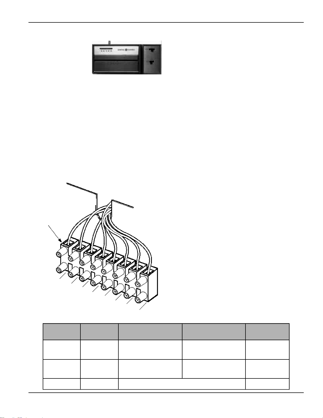
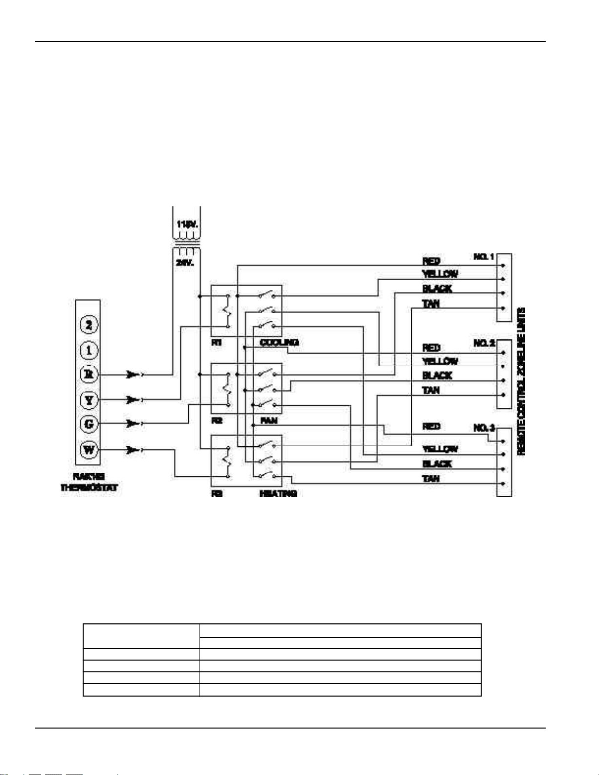
Remote Thermostat Control
Multiple Units Connected to One Remote
Thermostat (2200 Series)
One remote control thermostat may be used to control
multiple resistance heat Zoneline units, however the units
may not be wired direct. Since each Zoneline unit has an
integral transformer, direct wiring can result in a “bucking”
Remote Control (Low Voltage) Wiring
One stage Thermostat Controlling Three Zoneline Units
Resistance Heat Zoneline 2200 Series Units
(Not Applicable on Heat Pump Units)
or “boosting” voltage condition, and is in violation of the
National Electric Code. The diagram below shows the
correct wiring for such an installation through the use of
field supplied isolation relays.
NUMBER OF
UNITS CONTROLLED
2
3
4
MORE THAN 4
FIELD SUPPLIED RELAY SPECIFICATIONS
RELAY DESIGNATION
R1, R2, and R3
POTTER and BRUMFIELD TYPE KA11AY-24 OR EQUIVALENT
POTTER and BRUMFIELD TYPE KA14AY-24* OR EQUIVALENT
POTTER and BRUMFIELD TYPE KU17A11-24* OR EQUIVALENT
USE COMBINATION OF RELAYS SPECIFIED ABOVE
NOTE: Current draw through thermostat contacts should not exceed 1.0 amps.
*Special order, 100 piece minimum order.
Transformer
18 Va MIN
21
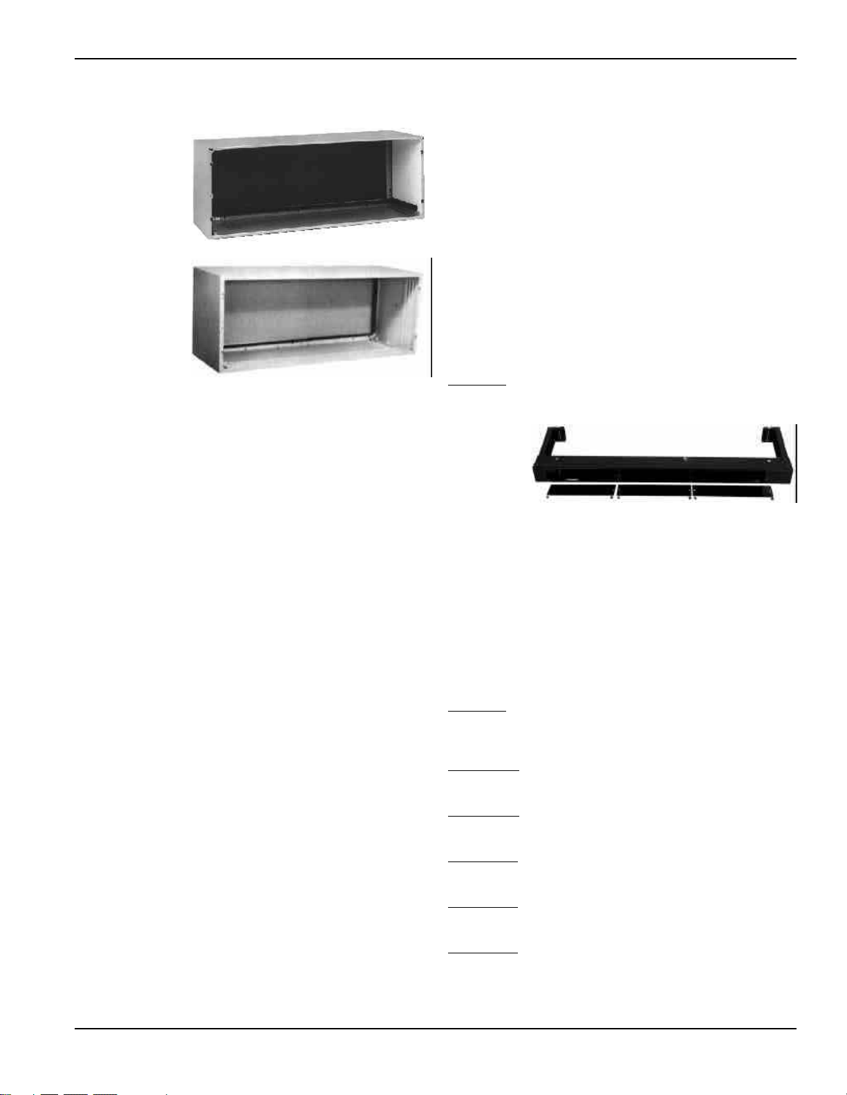
Wall Case
A choice of wall cases is available for the Zoneline.
RAB71 - This
insulated case is
constructed of
heavy gauge
galvanized steel
and finished with
a protective baked
enamel finish for
protection and
appearance.
Design of the case
provides for
support of the
chassis and free
draining of any
water entering
the wall case.
A petroleum
microcrystalline
wax is applied at
critical points of
fabrication to seal against moisture. The dimensions of the
RAB71 wall case are: 42" wide by 16" high by 13 3/4" deep,
the same dimensions as the original wall case for GE
Zonelines built in 1961.
RAB77 - This non-insulated wall case is molded from
fiberglass-reinforced polyester compound. This SMC (Sheet
Molded Compound) wall case offers outstanding strength,
durability, color retention, water integrity and corrosion
resistance. The dimensions of the RAB77 wall case are: 42
1/8" wide by 16 1/4" high by 13 7/8" deep.
• Both wall cases are of universal design, accepting all
Zoneline chassis of current design as well as all GE
Zoneline chassis produced since 1961.
• Drain holes are provided in the rear of the wall case to
permit excessive cooling condensate water, heat pump
condensate, or precipitation entering the wall case to
drain freely. A drain kit may be connected to the wall case
to control any water draining from the wall case. See pages
33 and 34 for information on RAD10 Drain Kit.
RAK901L - For installations when wall case extends into
room, an RAK901L is an insulation kit that can be used with
the RAB77 or any existing non-insulated wall case to
minimize the possibility of condensation forming on the
indoor side of the case.
Sub-Base
The sub-base is an optional accessory for the Zoneline and is
presented with the wall case information since the decision
to use or not to use a sub-base in the installation is a factor
in the location of the wall opening for the unit. National
Electrical Code
®
requires that air conditioning units
connected to voltages in excess of 250 volts be
“
permanently
connected
”
. There are also some installations where units
connected to voltage sources under 250 volts may also need
to be
“
permanently connected
”
. If you are in doubt about
the requirements for a particular installation being
designed, consult Article 440 of the NEC. These
requirements are designed to protect personal safety and
should be strictly followed. Although NEC is cited here as a
reference, all electrical wiring and installations must
conform to any and all local electrical codes and
regulations.
“Permanent Connection” generally means wiring between
the building wiring and the unit must be contained in an
enclosed “chaseway”, where access to the wiring connections
is more restrictive than a normal line cord plugged into a
receptacle. NEC requirements may be met by using flexible
or rigid conduit to contain the wiring between the unit and
a junction box that contains the wiring connections. The
conduit is connected to the unit and to the junction box
with connectors to hold the conduit in place. The junction
box may be located in the floor or the wall of the structure
but only approved connectors may be used outside the unit
or the junction box. The sub-base is UL
®
listed as a junction
box for permanent connection of a Zoneline.
Using a sub-base in an installation requiring permanent
connection provides a convenient, consistent location for
unit wiring to be connected to building wiring. The use of a
sub-base is not required, but the convenience and the
improved aesthetics it offers makes the use of a sub-base a
viable means of permanent connection.
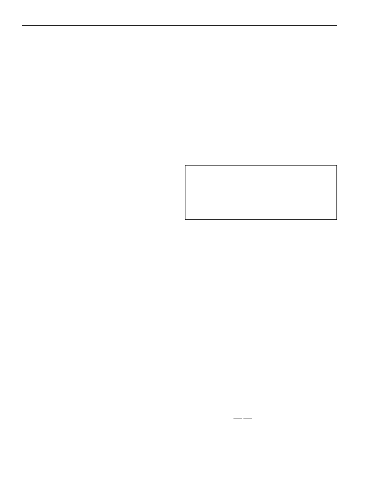
RAK204U
- The RAK204U Series of sub-bases provides a
variety of designs that fit the site needs and are available for
use with Zoneline PTAC/PTHP units. The RAK204U will
most likely be
used for
support of
the wall case
and unit.
The
RAK204U is
the same physically as the other sub-bases except there is no
receptacle installed. Receptacles and wiring can be field
installed and, by using the RAK205CW chaseway and the
RAK4002 junction box, performs the same function as any
of the other sub-base kits by selecting the correct receptacle
and installing it in the interior mounting plate inside the
RAK204U.
208/230 volt receptacles can also be mounted in the center
cover plate for easy access when direct connect wiring is not
required. 265 volt units are to be “Direct Connected” and the
external receptacle (not enclosed in a chaseway) does not
meet this requirement. Knockout for fuseholder
is provided.
RAK204U
No receptacle, no wiring, will accept any 15, 20,
30 amp receptacle and wiring. No chaseway is included.
Note: RAK205CW is the chaseway and must be ordered
separately.
RAK204D20
208/230 volt 15/20 amp receptacle. Note: 18
inch #12AWG wires attached to the receptacle. (Receptacle
NEMA6-20 GE4181-2) Chaseway included.
RAK204D30
208/230 volt 30 amp receptacle. Note: 18 inch
#12AWG wires attached to the receptacle. (Receptacle
NEMA6-30 GE4139-3) Chaseway included.
RAK204E15
265 volt 15 amp receptacle. Note: 18 inch
#12AWG wires attached to the receptacle. (Receptacle
NEMA7-15R GE0716-6) Chaseway included.
RAK204E20
265 volt 20 amp receptacle. Note: 18 inch
#12AWG wires attached to the receptacle. (Receptacle
NEMA7-20R GE0720-3 Chaseway included.
RAK204E30
265 volt 30 amp receptacle. Note: 18 inch
#12AWG wires attached to the receptacle. (Receptacle
NEMA7-30R GE0730) Chaseway included.
RAB77 Wall Case
RAB71 Wall Case
22
Sub-Base (Cont.)
Chaseway RAK205CW is included with RAK204D20,
RAK204D30, RAK204E15, RAK204E20 and the RAK204E30.
If the chaseway is needed when using the RAK204U, it must
be ordered separately as RAK205CW.
There are separate internal compartments to permit
separation of low voltage (Class 2) connections from line
voltage connections as required by NEC. Conduit containing
building wiring enters the sub-base through knockouts
located in the rear or bottom of the sub-base and is not
accessible when the wall case is installed.
The sub-base attaches to the RAB71 wall case with two clips
(field assembled) that are screwed into pre-drilled holes in
the bottom front flange of the wall case. It attaches to the
RAB77 wall case with clips that fit over molded ribs without
requiring the use of screws into the wall case. See page 31 for
illustration. Since the sub-base extends under the wall case,
clearance from the inner edge of the wall case to the
finished wall must be 2-3/8" or greater. The sub-base has 4
leveling legs and adjustable side channels to enable the area
under the wall case to be enclosed. Clearance from the
bottom edge of the wall case to the finished floor must be
between 3" and 5".
The sub-base may be used as support for the chassis and wall
case in installations where the wall is of insufficient thickness
to provide secure mounting of the wall case.
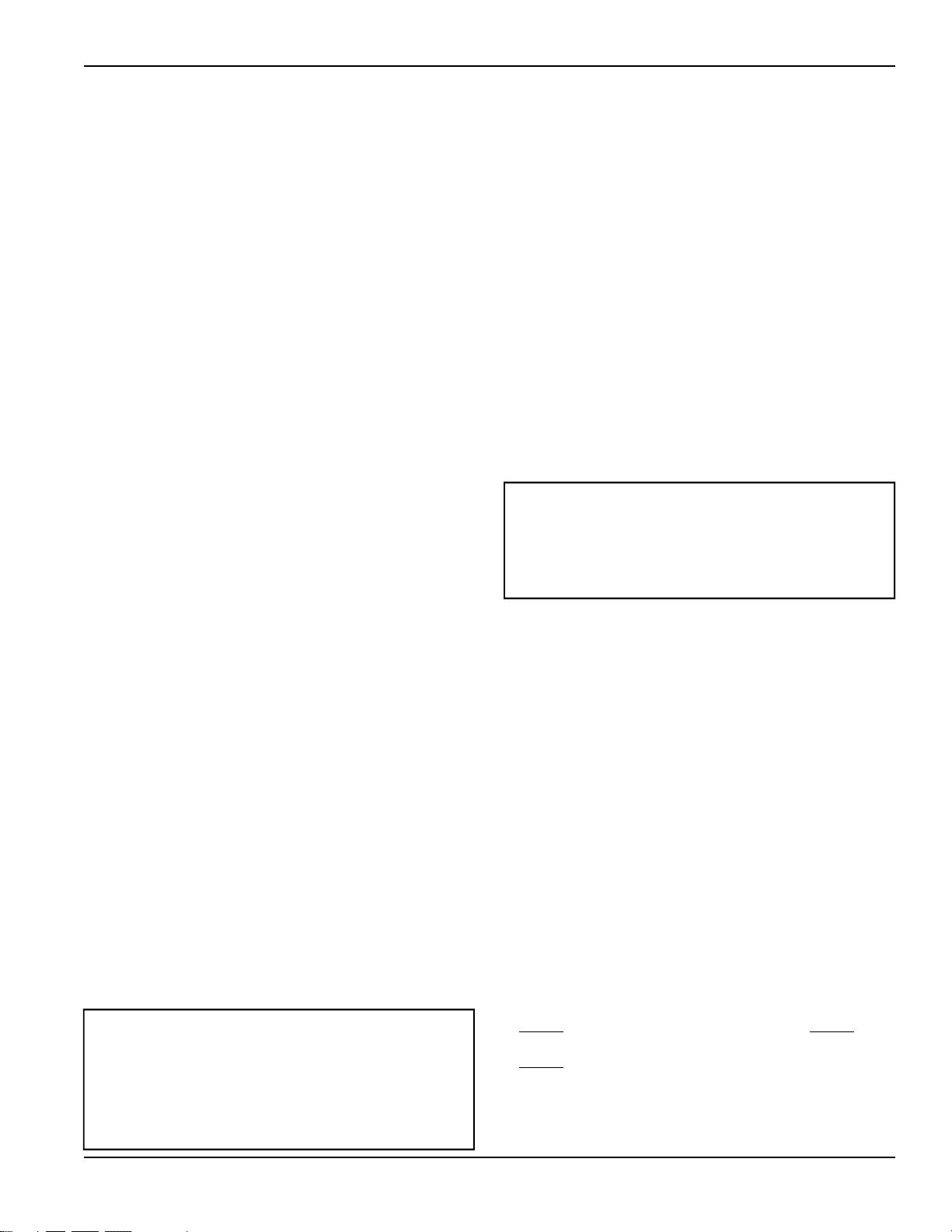
Wall Case Installation Data
General
Generally, Zonelines are installed 3" to 5" above the floor
(flush to finished floor installation is possible) as near to the
center of the room as possible; underneath a window or a
glass panel is typical. Normal installation of the wall case
allows installation flexibility; from flush with the finished
interior wall to a minimum of 1/4" of the wall case
extending beyond the finished exterior of the building.
Special consideration must be given to installations where
the wall case does not extend a minimum of 1/4" beyond
the finished exterior wall. See pages 28 and 29 for
information on this type of installation. The unit may be
installed high in the wall and these installations usually
require a remote thermostat and are discussed on page 18,
19, 27 and 42.
Regardless of the installation, there are several things to
consider when selecting a location for installing the unit.
For instance, drapery location could interfere with air
discharge, and placement of furniture may have an impact
on the performance of the unit. The following information
is intended to minimize installation problems and assure
you of trouble-free installation.
Refer to page 24 and 25 for required wall opening
dimensions. Minimum recommended interior and exterior
case projection for standard wall thicknesses are shown in
the drawings in this manual. The case may be installed flush
with the finished indoor wall. Special attention must be paid
to room-side case projection when the unit is installed in a
ducted application as shown on page 37, or with a sub base
as shown on page 25.
In walls thicker than 13 1/2" for line cord connected units
and 11 1/8" for sub-base installations, it may be necessary to
install a field fabricated case extension. If you are unable to
locate a local source for case extensions please contact your
salesperson for a possible supplier. Such extension must be
carefully flashed and sealed both to the wall case and to the
wall to insure water integrity. This is necessary to insure that
any water entering the wall case, either from operation of
the unit or from other sources, such as rain storms or from
washing the exterior of the building, will drain from the case
without the possibility of capillary action drawing the water
into either the room or the wall cavity. In an installation
where the case is recessed less than 3" from the outside
surface, flashing and sealing may be all the modificaton
necessary. In such an installation, the sides and top of the
wall opening must be waterproof to prevent moisture from
seeping into and damaging the walls. See Pages 28 and 29
for suggested detail.
When the outdoor grille or louver section is mounted to the
building face, causing a space between the outdoor coil and
the louver section, air splitters, aligned with the ends of the
outdoor coil, must be installed between the outdoor coil
inlet and outlet air streams. See page 41 for requirements for
custom louver sections.
For new construction, early planning with the architect is
necessary. Unit location, electrical connection locations, and
wall openings of the proper dimensions are essential to
avoid the necessity of rework, fillers, framing, moving
electrical outlets, and other expensive modifications.
For existing construction it is important that carpentry,
masonry and electrical work be performed by competent,
qualified personnel. Since installations in existing
construction may involve removal of building material from
the structure, locating the wall case must be done correctly.
Window, Curtain and Panel Wall Construction
With this type of construction, provision for support of the
unit, other than by the wall itself, is often required. Such
support may be in the form of wood or metallic material of
the proper thickness to maintain a level case. This
additional support should be located both near the wall and
at the front of the wall case. Sub-base (RAK204U Series)
with four leveling legs provides an excellent support for the
unit in this type of installation. See page 26 for details of this
type of installation.
In existing construction, common practice is to remove a
pane of glass, metal, wood, or other construction material
and build a frame around the wall case. Similar filler panel
material may be installed around the case for appearance
and weather seal.
Masonry Wall Construction
The wall case should be installed during construction and
lintels should be used to support the blocks above the wall
case. The wall case will
not support the concrete block. The
installation instructions show how the wall case must be
secured to the masonry and caulked. Do not remove the
cardboard stiffener supplied with the wall case until ready
The wall case should be level from side to side and front
to back. The condensate disposal system in the unit is
designed to dissipate the condensate water generated
during cooling operation in accordance with ARI
standards and actually uses this water to increase the
efficiency of the unit. A level unit will also insure proper
performance of the Internal Condensate Removal (ICR)
system optional on heat pump units.
23
Masonry Wall Construction (Cont.)
to install the chassis. See page 27 for details of installation in
masonry wall.
For existing masonry construction, wall openings must be
made. This normally involves the removal of concrete blocks
to achieve the proper size opening. Consult the builder,
architect, or owner to determine the necessity for lintels to
support the block above the wall case.
Anchor bolts are normally required to secure the case to the
wall and shims may be required to prevent distortion of the
wall case when securing the wall case to the wall. Field
supplied case angles can be used to position and secure the
wall case to the wall and to cover oversized wall openings.
Wall Case Installation Data
Brick, Frame, Stucco and Shingle Construction
For new construction, the opening for the wall case should
be framed and the wall case inserted into the opening
during construction. Lintels should be used when the
building material is heavy and is not self supporting (such as
brick). The wall case will fit an opening of six courses of
standard brick or five courses of jumbo brick. Wall framing
in this type construction is normally on 16" centers and the
wall case will fit a framed opening spanning three 16" O.C.
2" x 4" stud spaces.
For existing construction the indoor and outdoor wall will
need to be cut out, allowing for clearances of 1/8" on all
sides of the wall case. Work should begin on the inside wall.
Cut the correct dimensions and mark (using drill holes) the
outside wall from each corner of the inside cutout. Studding
that interferes with the opening must be removed and a
suitable frame constructed to secure the wall case and
provide adequate support for case and chassis.
Preparation of the Wall Case for All Types of
Construction
As shipped, the RAB71 or RAB77 is ready for installation.
Do not remove the stiffener from inside the wall case or the
weather closure panel from the outside face of the wall case
until the outdoor grille and chassis are ready to be installed.
Installation of Wall Case in Wall Opening
1. Position the wall case into the wall. The room side edge of
the RAB71 or RAB77 wall case should be at least flush
with the finished wall for line cord installations and
permanent connection installations when no sub-base is
used, and should project into the room at least 2-3/8"
when a sub-base is used. If the minimum exterior
dimensions are not met, refer to page 28 and 29. The
outside edge of the wall case should extend at least 1/4"
beyond the outside wall. This is necessary for proper
caulking, to prevent sealing the drain holes in the rear
flange of the wall case, and to facilitate the installation of
an accessory drain, if used.
2. The wall case should be secured to the wall at both sides.
Use a minimum of two screws or other fastening device on
each side. See Figure 2 page 24. Mark the wall case on
each side 2" from the bottom and 2" from the top at a
point where basic wall structure is located. Drill wall case
and use fasteners appropriate for wall construction. All
holes for fasteners in the side of the wall case must be at
least 2" up from the bottom of the wall case. Never locate
screws or put other holes in the bottom of the wall case.
The only exception is when an RAD10 drain kit is
installed to connect to an internal drain system. See page
34 for RAD10 Drain Kit information.
If the wall opening is greater than the case dimensions,
spacers must be used on the sides between the wall case
and the wall support structure to prevent distorting the
wall case.
3. Caulk or gasket the entire opening on the outside between
the wall case and exterior wall surface (4 sides) to provide
total water and air seal.
4. Caulk or gasket room-side opening between wall case and
interior wall surface (4 sides). Opening beneath or
around the wall case can allow outdoor air to leak into the
room resulting in increased operating costs and improper
room temperature control.
Case Angles
In some installations such as curtain walls, window walls, or
where the structural material of the wall is insufficient to
support or fasten wall case to, the use of case angles may be
used. Case angles are pieces of steel or other material of
similar structural strength that are formed to a 90° angle,
with holes to fasten the case angle to the wall case and to the
structural component of the wall surrounding the
wall case.
The following describes the procedure when field fabricated
and installed case angles are applied.
1. Position case angles around top and sides of wall case at
the desired location. Position case angles vertically on
each side of wall case to provide a level installation.
2. Mark wall case through holes in case angles. The lowest
hole on the sides of the wall case must be a minimum of
2" above the bottom of the case
3. For RAB71 wall case drill 5/32" diameter holes at
locations marked on wall case in Step 2, and assemble
angles to wall case using #10 x 1/2" self tapping screws.
For RAB77 wall case follow the same procedure except use
a #10 x 1/2" bolt, washer and nut to attach case angles to
case. Install screws or bolts from outside
wall case.
4. Do not
drill any holes in bottom of wall case. Do not
distort wall case.
5. Do not
use case angles for a lintel.
The wall case should be level from side to side and front
to back. The condensate disposal system in the unit is
designed to dissipate the condensate water generated
during cooling operation in accordance with ARI
standards and actually uses this water for maximum unit
efficiency. A level unit will also insure proper
performance of the Internal Condensate Removal (ICR)
system optional on heat pump units.
Care should be taken in location of electrical supply entry
in relationship to wall sleeve to assure access to receptacle
or junction box once unit is installed.
• Refer to page 38 for maximum power cord length.
• Permanent connected units close to finished floor must
allow for conduit clearance.

24
MAIN STUD
JACK STUDS
JACK STUD
SUB-FLOOR
CRIPPLE
FINISHED FLOOR
HEADER – 4” x 4” OR
2 - 2” x 4” ON EDGE
16-1/4” MIN. RAB71
16-1/2” MIN. RAB77
ADJUSTABLE FRAMING TO SECURE
THIS DIMENSION
42-1/4” MIN. (RAB71)
42-3/8” MIN. (RAB77)
MAIN STUDS
JACK STUD
HEADER
MOUNTING
SCREW HOLE
NO HOLES PERMITTED
IN BOTTOM OF CASE
(EXCEPTION - RAD10
DRAIN KIT)
Framing detail for this construction is as
shown in Figure 1. Note use of lintel
under first course of brick above the
Zoneline case. Do not use the case as a
lintel. Mounting screw holes shown are
to be made by the installer.
WOOD
SCREW
MAIN STUD
JACK STUD
MOLLY
OR TOGGLE
BOLT
EXPANSION
ANCHOR
BOLT
Choice of attachment devices
through both ends of case or the
top. Mounting screw holes and
attachment devices by installer.
NO HOLES PERMITTED IN
BOTTOM OF CASE
(EXCEPTION - RAD10
DRAIN KIT)
2” MIN.
Note: Do not remove the stiffener
support from inside the wall case
until the chassis is to be installed.
Figure 1
FRAMING FOR WALL CASE
BRICK VENEER AND FRAME CONSTRUCTION
FASTENING WALL CASE
Figure 2
LINTEL
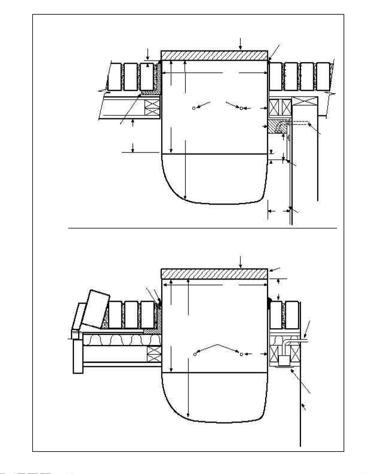
25
LINTEL
Cord Set Connected
WALL SECTION – DETAILED SIDE VIEW
FRAME AND BRICK VENEER INSTALLATION
Sub-Base Connected
STEEL LINTEL
CAULK*
RAB71 13-3/4”
RAB77 13-7/8”
20-7/8” (RAB71)
21” (RAB77)
MOUNTING SCREWS
BY INSTALLER
RAB71 16”
RAB77 16-1/4”
OUTDOOR
GRILLE
2” MIN.
WALL CASE
ROOM
CABINET
1/4”
MIN.
WALL RECEPTACLE
(BY OTHERS)
POWER SUPPLY
CONDUIT
*Caulk around perimeter of wall case all four sides
where it joins the building.
RAG60 1/4”
RAG61, 62, 63 1-3/8”
RAG64, 65, 66 1-3/8”
RAB71 13-3/4”
RAB77 13-7/8”
20-7/8” (RAB71)
21” (RAB77)
MOUNTING SCREWS
BY INSTALLER
RAB71 16”
RAB77 16-1/4”
OUTDOOR
GRILLE
2” MIN.
WALL CASE
ROOM
CABINET
SIDE CHANNEL
SUB-BASE
(RAK204)
FINISHED FLOOR
OR TOP OF
CARPET
POWER SUPPLY CONDUIT
(ALTERNATE ENTRY)
Caulk around
perimeter of wall
case all four
sides where it
joins the building.
3” MIN.
5” MAX.
1/4”
3-11/16”
1-5/16”
FINISHED FLOOR
OR TOP OF
CARPET

30
RAB71/77 WALL CASE INSTALLATION - RAK204 SERIES SUB-BASE CONNECTED
EXAMPLE: FRAME & BRICK VENEER - DIMENSIONAL DATA AND COMMENTS
ARE ALSO APPLICABLE TO OTHER TYPES OF CONSTRUCTION
FINISHED
INTERIOR
WALL
LEVELING SCREW
LEVELING SCREW
2-3/8
”
MIN.
TOP VIEW
RAB71 13-3/4
”
RAB77 13-7/8
”
3
”
7/8”
1-1/2”
1-7/16”
2-3/8”
SIDE VIEW
WITH WALL
CASE SHOWN
IN PLACE
RAB71 16”
RAB77 16-1/4”
3” MIN.
ADJUSTABLE
TO 5”
FINISHED FLOOR
INTERIOR
WALL
3-11/16”
C
13-3/4”
A
MAX. WALL THICKNESS
11-1/8”
MOUNTING SCREWS
AND HOLES BY
INSTALLER
RAB71 16”
RAB77 16-1/4”
Caulk around
perimeter of
wall case all
four sides
where it joins
the building.
B
ROOM
CABINET
LEVELING SCREWS
(2) SUB-BASE
(2) SIDE EXTENSIONS
SIDE VIEW
CONDUIT ENTRY
(ALTERNATES)
2-3/8” MIN. CASE
EDGE TO FINISHED
WALL
RECOMMEND 2” TO
INTERIOR ADJACENT
WALL BOTH SIDES.
SEE NOTE
LEFT SIDE
LEVELING SCREW
KNOCKOUTS
(ENCLOSURE)
4 REAR; 4 BOTTOM
FRONT VIEW*
INTERIOR
ADJACENT
WALL
*SHOWN WITH ACCESS COVERS REMOVED.
NOTE: CAUTION - REMOVE KNOCKOUTS FROM INSIDE OUT.
D
3-1/2”
7-3/4”
19”
12.90”
7-3/4”
D42”
KNOCKOUT SIZE
LARGE 1-1/8” DIA.
SMALL 7/8” DIA.
Manufacturer Required
Dimension Minimum Installation Clearance
A 1/4
”
(See note 1)
B3
”
Min. (5
”
Max.)
C 2-3/8
”
Minimum
D0
”
Minimum 2
”
Recommended
See pages 35-36 for ducted applicaton.
NOTE:
1. FOR OUTSIDE FLUSH MOUNTING SEE PAGE 34 FOR DRAIN
INSTALLATION.
1-5/16”
1-7/16”
FINISHED FLOOR
5.15”
7.70”
8.80”
10.30”
BACK VIEW
5.15” 7.70” 18.86” 1.5”
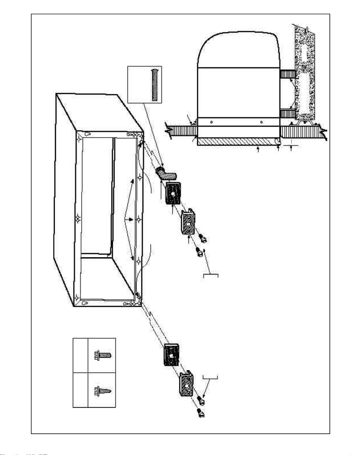
33
WALL CASE WITH RAD10 DRAIN KIT
EXTERNAL DRAIN
SEE PAGE 34 FOR INTERNAL DRAIN
SEE PAGE 34 NOTE #6
SQUARE DRAIN HOLES
1/2” O.D. 90° ELBOW DRAIN TUBE
NEOPRENE SPONGE GASKET
STEEL MOUNTING PLATE
Alternate
6” long, 1/2”
O.D. straight
copper tube.
NOTE: SHADED PARTS AND
SCREWS ARE INCLUDED
WITH RAD10 DRAIN KIT.
USE EITHER THE 90°
ELBOW TUBE OR THE
STRAIGHT TUBE
DEPENDING UPON THE
REQUIREMENTS OF THE
PARTICULAR
INSTALLATION.
USE TYPE “A” SCREW FOR METAL CASE (RAB71)
AND TYPE “B” SCREW FOR MOLDED CASE (RAB77)
TYPICAL INSTALLATION
CASE ANGLES (FIELD SUPPLIED)
REAR
GRILLE
WALL CASE
ROOM
CABINET
90° ELBOW
DRAIN TUBE
PROJECTION
BEYOND WALL
CASE
MIN. 2 SUPPORTS
FIELD SUPPLIED
FLOOR
Caulk around
perimeter of
wall case all
four sides
where it joins
the building.
3”
4
“A” “B”
METAL PLASTIC
SCREWS
WATER DRAINAGE - Precipitation entering the unit through the outdoor louver may not be removed entirely by the
condensate removal system. The base pan flange is designed to allow excess water, either condensate water or
precipitation, to flow into the wall case and drain through two drain holes in the rear of the wall case. If there is more
water in the wall case than can be drained through these holes it will drain through the three overflow drain holes.
These drain holes must not be blocked when mounting or caulking the wall case.
For those installations where water draining from the drain holes is objectionable or where positive drainage is
desired, the RAD10 drain kit is available with either a 90° elbow or a 6” straight tube to be used either to connect to a
field supplied drain line or to allow the water to drip free rather than drain down the surface of the building.
NOTE: Drain kit using either the 90° elbow tube or the straight tube may be installed without modification when using
RAG60 exterior grille. Drain kit using the 90° elbow tube may be installed without modification when using RAG61
through RAG66 exterior grilles. Modification must be made to the RAG61 through RAG66 exterior grilles when using
the straight tube. Modification must be made to the RAG67 grille if using either the 90° elbow tube or the straight tube
(see installation instructions with the RAG67 grille).

36
DUCTED APPLICATION (AZ2200/3200 SERIES)
RAK6052
ADAPTER
TRANSITION
RAK601
44” LENGTH
DUCT ADAPTER EXTENSION HAS 1/2” INSULATION
NOTES:
1. RAK6052 kit includes duct adapter, transition and mounting hardware.
2. RAK601 duct extension may be installed at either end of the RAK6052 duct adapter.
Maximum duct extension length is 15’. Duct extension must be field fabricated for
installations where length of duct exceeds length of RAK601 (44”). Field fabricated duct
extension must be insulated to prevent condensation from forming on exterior. Duct
extension may not contain bends or turns.
3. Ducted units may need to be permanently connected. Check local code for specific
electrical installation requirements.
4. Duct extension kit RAK601 contains 44” duct extension, discharge grille mounting collar,
and discharge grille. Duct extension must be cut to required length. Two ducted
installations may be made from one kit if the combined ducted length is less than 44”.
RAK602 kit contains mounting collar, discharge grille and mounting hardware necessary
for second installation.
5. Filler strip (field supplied) actual width depends upon wall case projection into room.
A flush installation to finished wall (i.e., no filler strip) can be made.
6. Unit must be installed to provide at least a 1” clearance between side of unit and wall.
7. Provisions for return air must be made in order to allow air circulation from secondary
room. Doors in both secondary and primary rooms may be undercut or a return grille
may be installed through common wall.
8. For replacement of previous design units, see page 35.
RECOMMENDED
MINIMUM
CLEARANCE
2” TO SIDE WALL
8” high
44”
7-3/8”
wide

37
Line Cord Installation
DUCTED DETAILED SIDE VIEWS (AZ2200/3200 SERIES)
SEE PAGE 36 FOR ALL NOTES
Sub-Base Installation
*Caulk around perimeter of wall case all four sides
where it joins the building.
Caulk around
perimeter of
wall case all
four sides
where it joins
the building.
2-29/32”
RAK6052
ADAPTER
ROOM
CABINET
WALL CASE
FINISHED
FLOOR
CAULK*
3/4” MIN.
WALL TO
CASE EDGE
RECEPTACLE
(BY OTHERS
ALT. LOCATIONS)
RAG60 - 1/4”
RAG61-66 - 1-3/8”
2-29/32”
RAK6052
ADAPTER
ROOM
CABINET
WALL CASE
FINISHED
FLOOR
RAG60 - 1/4”
RAG61-66 - 1-3/8”
1-5/8”*
MIN.
* 2-3/8” min. when installed with RAK204.
3-11/16”
RAK
204
3” MIN.
5” MAX.
1/4”
FILLER STRIP (SEE NOTE 5 ON PAGE 36)
6-1/2”
7-3/32”
16-1/8”
11-1/8”
MAX.
16-1/8”
10”
7-3/32”
6-1/2”
ANY CONSTRUCTION
12-3/4”
MAX.
1/4”
MIN.
TRANSITION
TRANSITION
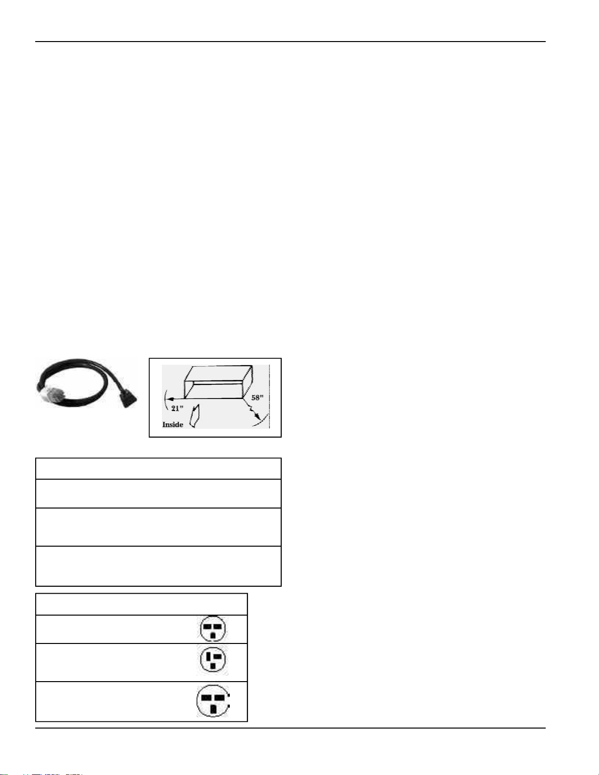
38
Power Connection Kits For
Premium Series (5200)
The Zoneline 5200 series units are connected to the
building power supply by a unique power connection kit. By
utilizing a separate universal power connection (UPC) kit,
each unit is capable of providing various outputs of electric
resistance heat to more closely meet the heating
requirements of the particular room, thereby increasing the
installation flexibility of the particular chassis. This power
connection kit is the only means of supplying power to the
Zoneline chassis and the appropriate kit is determined by
the voltage, the means of electrical connecton - either line
cord connected or permanent connected - and the desired
resistance heat output that may be supported by the branch
circuit.
230/208 Volt Installations
Connections to 208 or 230 volt circuits may be made with a
line cord power connection kit.
Line Cord Kits consist of a self-aligning 9-pin molded
connector that plugs into a mating connector on the
Zoneline chassis and insulated line cord with an electrical
plug on the end. The configuration of the electrical plug
conforms to NEC standards for the circuit amperage and the
postion of the wires in the 9-pin connector determines the
heater wattage and current requirements when it is plugged
into the Zoneline chassis. Permanent
Connection is accomplished by ordering the correct
ampacity electrical sub-base to match the Power Cord being
used. See page 21 Sub-Base for description.
There may be special requirements by some sites that rigid
or flexible conduit be used. (Such as the wall case must be
installed flush to finished floor and there is no room for a
sub-base.) In these installations the RAK4002 junction box
will be needed and the Power Cord/Cord Set will be cut and
connected to building wiring inside the RAK4002 junction
box. Conduit will be attached to the RAK4002 and to the
site supplied building/room junction box where the
building wiring enters the room. Wiring will be totally
enclosed by conduit and junction boxes.
Maximum Cord Extension
Premium
Typical Line Cord
Power Connection Kit
Line Cord Heater Circuit Protective
Kit Voltage KW Ampacity Device
RAK3152 230/208 2.55/2.09 15 Amp 15 Amp
Time Delay
Fuse or Breaker
RAK3202 230/208 3.45/2.82 20 Amp 20 Amp
Time Delay
Fuse or Breaker
RAK3302 230/208 5.00/4.09 30 Amp 30 Amp
Time Delay
Fuse or Breaker
Receptacle
Type Mfg Part No Configuration
15 AMP GE GE4069
Tandem Hubbell 5661
NEMA6-15R P&S 5661
20 AMP GE GE4182
Perpen- Hubbell 5461
dicular P&S 5871
NEMA6-20R
30 AMP GE GE4139-3
Large Hubbell 9330
Tandem P&S 5930
NEMA6-30R
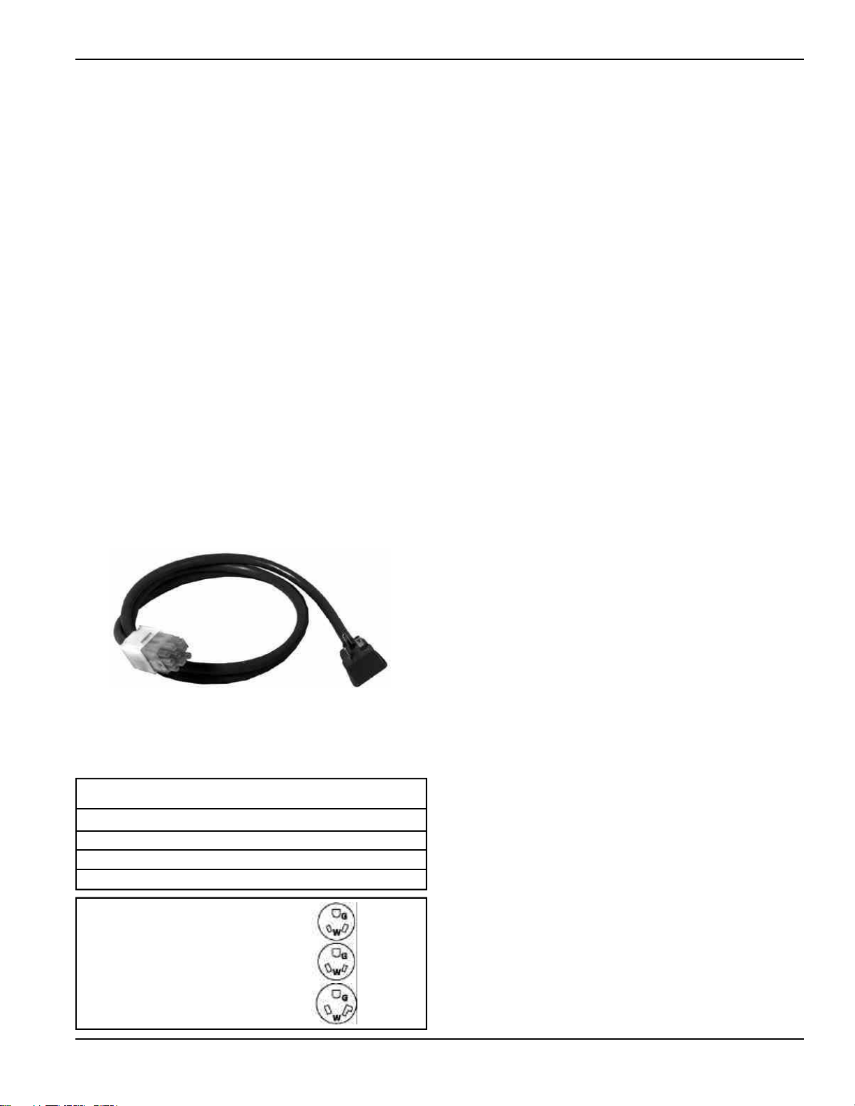
39
Power Connection Kits For
Premium Series (5200)
265 or 277 Volt Installations
National Electrical Code (Article 440 section G) requires
permanent connection for installation on circuit in excess of
250 volts.
Permanent Connection Kits are available for 265 volt
installations. The regular kit consists of a self-aligning
9-pin connector that plugs into a mating connector on the
chassis, a length of power cord with the plug cap molded to
the end. There are four 265 volt cord sets so that the desired
heater KW will be achieved when the correct RAK5*** kit is
selected. See chart below for guide. These cord sets will
match the receptacle in the RAK204E Series sub-base. It is
important that care be used in this selection process. This
cord set, when used with the appropriate sub-base with
provided chase way from the junction box to the sub-base, is
considered to be permanently connected.
For those installations that require a method of direct
connection using flexible or rigid conduit, the RAK4002
junction box (provided with chassis) can be used and the
field supplied conduit attached to it. The universal cord set
will be cut off and connections made inside the
junction box.
Electrical Wiring Information
For all installations feeder, sub-feeder, branch circuit and
electrical protective devices and selection must conform to
the National Electrical Code and to local codes.
Maximum connected load in amperes, including demands
for the electric heater and the fan motor, are shown on page
54. Branch circuit ampacity and electrical protective device
sizing are shown at left. More than one unit per branch
circuit is not recommended; however, when in doubt,
consult the National Electrical Code. All wiring, including
installation of receptacle, must conform to local electrical
regulations and codes.
Replacement of Existing Chassis
230/208 Volt and 265 Volt Units
There have been changes to NEC and improvements and
modifications to the Zoneline chassis and sub-bases since
the unit was first introduced. Some of these changes require
alterations to be made when replacing an older unit with a
new chassis.
Line Cord Connected Units
The plug configuration of new line cord connected units
complies with the current NEC standards. Older
installations may have wall receptacles that conformed to
NEC standards at the time the building was constructed and
may not match the configuration of the plug on the new
line cord. Recommended solution is to change the wall
receptacle to conform to current standard plug
configuration. See chart on page 38 for current receptacle
configuration.
Permanent Connected Units With Sub-base
If the existing unit is connected to a sub-base the installation
of the new unit may involve modifying the existing
installation slightly. It is recommended these modifications
be made by a qualified electrician.
If the existing sub-base is the full width of the wall case,
RAK201 sub-base access plate may be ordered and used to
replace the cover on the old sub-base. Field supplied wiring,
conduit and conduit connectors should be used to make
connection between new chassis and the center knockout of
the RAK201. The wiring connections should be made inside
the sub-base and the RAK201 attached to the sub-base with
the 2 screws provided.
If the existing sub-base is not the full width of the wall case
the electrician will have to modify the existing cover plate to
allow field supplied wiring, conduit, and conduit connectors
to be run from the permanent connection kit to the sub-
base.
NEMA7-15R; receptacle used on 265V sub-base
GE0715
NEMA7-20R; receptacle used on 265V sub-base
GE0720-3
NEMA7-30R; receptacle used on 265V sub-base
GE073
Permanent Heater Circuit Protective Device
Connection Kit Voltage KW Ampacity (Fuse Included)
RAK5152 265 1.7 15 Amp 15 Amp
RAK5172 265 3.0 15 Amp 15 Amp
RAK5202 265 3.7 20 Amp 20 Amp
RAK5302 265 5.0 30 Amp 30 Amp
15 Amp
20 Amp
30 Amp
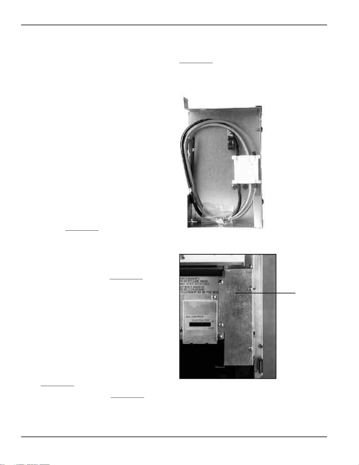
40
Power Connection For Deluxe
Series (2200 & 3200)
The Zoneline 2200 and 3200 series units have discrete
heater wattages. Each unit has a factory installed heater and
must be installed on an electrical circuit with sufficient over-
current protection to carry the amperage load of the unit.
See specifications on page 52 for model number
nomenclature, heater amperage, and minimum circuit
ampacity for the particular Zoneline model. To determine
maximum connected load for individual model see page 54
and 55.
230/208 Volt Unit Installation - Line Cord Connected Units
Zoneline 2200 and 3200 series units for installation on 230
or 208 volt circuits have a factory installed line cord with a
plug conforming to NEC standards for the circuit amperage.
Graphic representation of the wall receptacles are shown on
page 38. The line cord length is also shown on page 38.
230/208 Volt Unit Installation - Permanent Connected Units
If a permanent, or direct wired, installation of a 230 or 208
volt units is desired, a junction box kit, RAK4002, is available
to allow direct connection when the 208/230 volt chassis is
installed with the appropriate electrical sub-base. When the
cord set is enclosed by the RAK4002 and the sub-base chase
way RAK205CW, the wiring is totally enclosed and the unit is
considered to be permanently connected. (correct ampacity
RAK204 series sub-base required)
If an installation using flexible conduit is desired, the
RAK4002 kit mounts to the chassis to form an enclosed
junction box with a removable front panel for access to the
unit wiring. A 7/8" diameter hole in the bottom of the
enclosure enables field supplied
rigid or flexible conduit to
be connected to the kit. A wiring harness of three
conductors and an in-line connector is included with the
RAK4002.
The factory installed line cord must be cut off approximately
8" from where it comes through the barrier, or bulkhead, of
the unit. Strip insulation off 3/4" of each conductor to
expose wire for field connection. These wires are then
connected to the building wiring by field supplied
connectors.
265 or 277 Volt Unit Installation - Permanent Connected
Units
National Electric Code (Article 440 Section G) requires
permanent connection for units connected to power sources
over 250 volts, therefore these units must be permanently
connected (direct wired).
Zoneline 2200 or 3200 series units rated for installation on
265 volt circuits have discrete heater wattages and the
appropriate cord set to match the 265 volt sub-base
receptacle installed in this sub-base. When installed with the
correct sub-base and chaseway the wiring is totally enclosed
and the installation is considered to be permanently
connected.
If an installation using flexible conduit is desired, the 7/8"
diameter hole in the bottom of the RAK4002 junction box
enables field supplied
rigid or flexible conduit to be
connected to the unit. A knockout is provided in the
junction box for the installation of a field supplied
cartridge
type fuse, if required. A wiring harness of three conductors
and an in-line connector is included with the RAK4002.
This wiring harness can be ordered separately as
RAK4002CW.
When direct connecting the unit, connections to the
RAK4002
Installed
building wiring should be made in the junction box with
field supplied
connectors.
All wiring must conform to local electrical regulations and
codes.
RAK4002
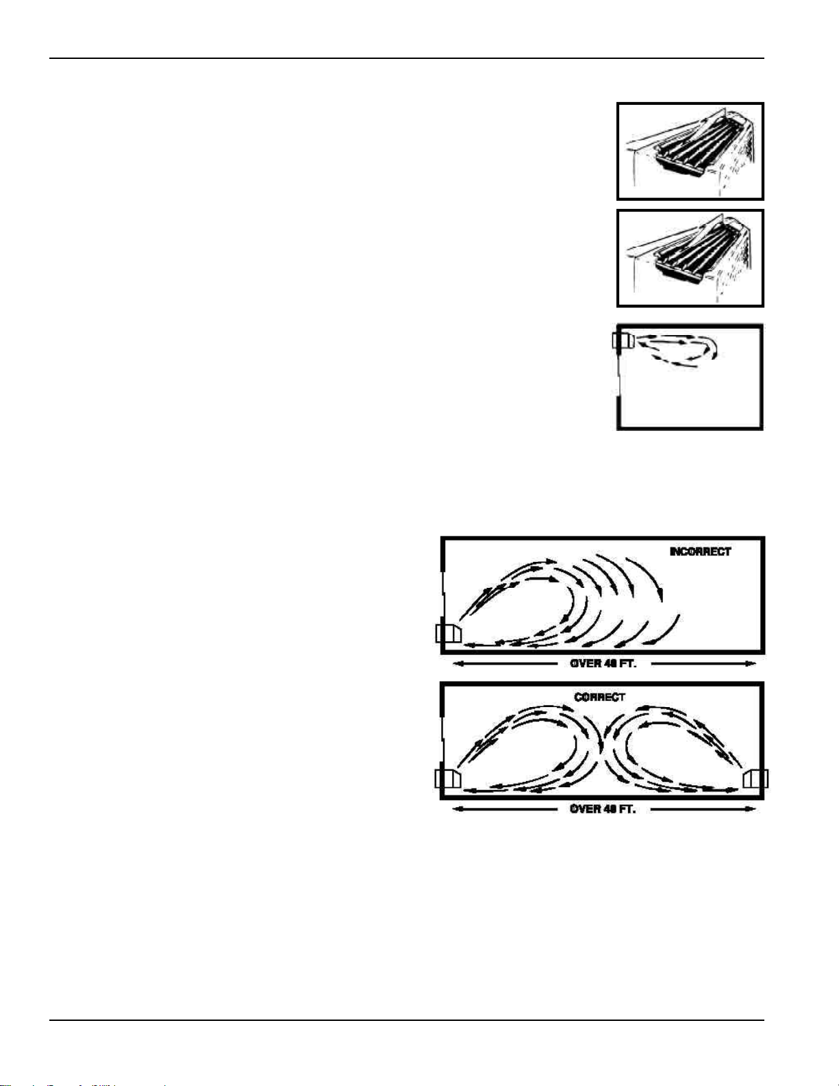
42
Application Comments
Use and Care Manual and installation instructions are
shipped with Zoneline units. It is important that any air
conditioning system be properly sized and applied in order
to achieve the desired temperature and humidity levels with
the space to be conditioned. Air conditioners are designed
primarily to provide heating and cooling with the additional
benefit that during operation in the cooling mode, the units
also remove some moisture from the conditioned space. The
following are some brief application comments on
undersizing, oversizing, heating, wall coverings, and air
infiltration: all are important in the proper matching of the
heating/air conditioning system to the building structure.
Undersizing: If an air conditioner is undersized (cooling
capacity is less than required for a specific application), the
unit will typically not be able to cool the space down to the
desired temperature (thermostat set point), nor be able to
remove enough moisture from the air. A result could be a
warm and humid or warm and dry conditioned space.
Oversizing: If an air conditioner is oversized (cooling
capacity is greater than required for the specific
application), the unit will typically cool the space down to
the desired temperature (thermostat set point) too quickly.
The compressor then begins to cycle on and off.
Dehumidification only takes place when the compressor is
operating. A typical result in a hot/humid climate could be
a cool, but excessively humid space.
Heating: Undersizing can result in not being able to
maintain the desired temperature level within the
conditioned space.
Wall Covering: Use of a non-permeable wall covering (some
paints, some wall papers, and other types of coverings)
which severely restricts passage of air or water vapor can
cause a severe moisture problem. Typical results could be
staining of room surfaces, wall damage, as well as mold and
mildew growth in hot/humid climates.
Air Infiltration: Excessive air infiltration can magnify
problems associated with undersizing or oversizing of an air
conditioner unit, and can be the root cause of insufficient
cooling, dehumidification, or heating. Some sources of air
infiltration include vents, gaps around windows and doors,
and improperly sealed floor, ceiling and wall joints.
Recommendation
For the above reasons it is strongly recommended that a
professional engineer be retained to match the Zoneline
with the building structure.
Air Distribution
Zoneline packaged terminal air conditioners and heat
pumps discharge air from the top of the unit through
reversible 2-position discharge louvers. Unit discharge
louvers are reversed by removing the room cabinet from the
unit, removing seven screws that hold the louver section in
place, removing the louver section and rotating it end for
end, reinstalling the louver section in the room cabinet with
the seven screws, and reinstalling the room cabinet on the
unit. The unit is shipped from the factory with the discharge
louvers at an angle of 50° off vertical. In the alternate
position the louvers will be at an angle of 40°
off vertical.
All room cabinets return air through the front of the unit.
High Wall Mount - For units
mounted high in the wall, the
discharge louvers should be at a
setting that provides the most
horizontal air discharge.
Recommended installation is at
least 3" below the ceiling. In
installations where units are
close to the ceiling, the most
horizontal discharge angle can
be obtained by removing the
discharge grill from the room
cabinet.
Supply Air Throw - One
Zoneline unit should not be
required to do a job obviously
requiring two or more units.
Units should be located around
large rooms according to
calculated loads or in such
fashion as to achieve balanced
air distribution in all parts of
the room. The single unit in
the “Incorrect” illustration
below obviously cannot
condition the entire room. Add
a second unit as shown in the
“Correct” illustration.
40°
50°

43
Cooling Performance Data
Heat Pump Performance Data
Temperature
of Air Entering
Condenser
65
75
85
95
105
115
Total Capacity - BTU/Hr.
BTUH At 80 °F D.B. - 67 °F W.B.
AZ AZ AZ AZ
22E07D 22E09D 22E12D 22E15D
22E07E 22E09E 22E12E 22E15E
7800 10000 12950 17900
7750 9900 12800 15900
7500 9600 12500 15500
7100 9000 11700 14600
6600 8250 10750 13600
6000 7500 9650 12300
Zoneline 2200 Series
AZ AZ AZ AZ
32H07D 32H09D 32H12D 32H15D
32H07E 32H09E 32H12E 32H15E
7800 10000 12950 17900
7750 9900 12800 15900
7500 9600 12500 15500
7100 9000 11700 14600
6600 8250 10750 13600
6000 7500 9650 12300
Zoneline 3200 Series
AZ AZ AZ AZ
52H07D 52H09D 52H12D 52H15D
52H07E 52H09E 52H12E 52H15E
7800 10000 13050 18000
7750 9900 12900 16000
7500 9600 12600 15600
7100 9000 11800 14700
6600 8250 10850 13700
6000 7500 9750 12400
Zoneline 5200 Series
AZ52H07D AZ52H09D AZ52H12D AZ52H15D
AZ52H07E AZ52H09E AZ52H12E AZ52H15E
Zoneline 5200 Series
Outdoor
Temperature F° BTUH COP BTUH COP BTUH COP BTUH COP
65 7200 3.75 10000 3.75 13050 3.55 15950 3.35
60 7000 3.70 9600 3.70 12550 3.50 15300 3.30
55 6800 3.65 9100 3.65 11950 3.45 14650 3.25
50 6600 3.55 8700 3.55 11350 3.35 13850 3.15
47 6400 3.50 8400 3.50 10900 3.30 13400 3.10
45 6250 3.45 8200 3.45 10600 3.25 13050 3.05
40 5950 3.35 7700 3.30 9800 3.10 12250 2.95
35 5550 3.20 7100 3.20 9000 3.00 11300 2.80
30 5150 3.05 6500 3.05 8200 2.85 10300 2.65
25 4700 2.90 5900 2.85 7300 2.65 9250 2.50
Capacities and COP at Various Outdoor Temperatures
BTUH At 70°F Indoor Temperature
Zoneline 3200 Series
AZ32H07D AZ32H09D AZ32H12D AZ32H15D
AZ32H07E AZ32H09E AZ32H12E AZ32H15E
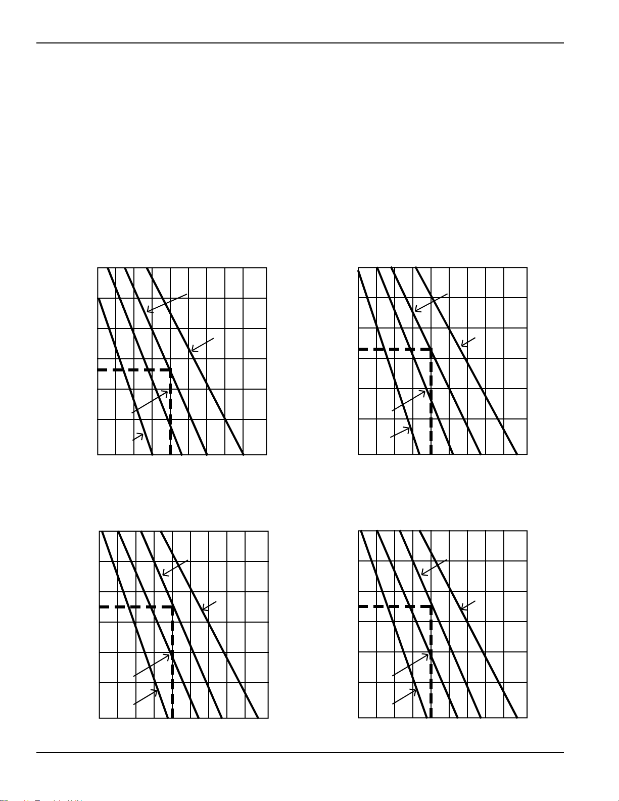
44
Latent System Capacity
The total capacity of an air conditioner is made up of the
Sensible capacity, the output of the unit used to remove heat
from the air in the area being conditioned, and the Latent
capacity, the output of the unit used to dehumidify the air
in the area being conditioned. For humid climates and
applications, the Sensible/Latent capacity split of the unit
should be considered. The Sensible capacity listed in the
specification charts on pages 52 and 53 are at standard
rating conditions of 95°F. dry bulb/75°F. wet bulb outdoors;
80°F. dry bulb/67°F. wet bulb indoors. The Latent system
capacity is 1.00 minus the Sensible capacity. (If the Sensible
capacity is listed at .74 the Latent capacity is .26. This means
that 74% of the capacity of the unit is used to remove heat
from the air and 26% is used to remove moisture from the
air at standard test conditions).
In some applications information about the Sensible/Latent
split, or ratio, at conditions other than the standard rating
conditions is needed. The charts below provide data at
various indoor conditions. To use the charts, first determine
which Zoneline model is being considered and refer to the
appropriate chart. Next, locate the indoor dry bulb
temperature under consideration across the horizontal axis
of the chart and draw a line straight up until it touches the
line representing the indoor wet bulb temperature of the
area; from this point draw a horizontal straight line to the
vertical axis. The point where the line touches the axis
represents the latent percent of the total capacity of the unit.
An example is shown for the standard indoor conditions of
80°F. dry bulb/67°F. wet bulb.
AZ22E15D/E AZ32H15D/E
AZ52H15D/E
SHR 65%
L
a
t
e
n
t
%
o
f
T
o
t
a
l
60
50
40
30
20
10
0
60 65 70 75 80 85 90 95 100
105°F
Degrees (Indoor Dry Bulb)
67 °F W.B.
Indoor Wet Bulb Temp
71°F W.B.
63°F W.B.
59°F W.B.
AZ22E07D/E AZ32H07D/E
AZ52H07D/E
SHR 74%
L
a
t
e
n
t
%
o
f
T
o
t
a
l
60
50
40
30
20
10
0
60 65 70 75 80 85 90 95 100
105°F
Degrees (Indoor Dry Bulb)
67 °F W.B.
Indoor Wet Bulb Temp
71°F W.B.
63°F W.B.
59°F W.B.
AZ22E09D/E AZ32H09D/E
AZ52H09D/E
SHR 67%
L
a
t
e
n
t
%
o
f
T
o
t
a
l
60
50
40
30
20
10
0
60 65 70 75 80 85 90 95 100
105°F
Degrees (Indoor Dry Bulb)
67 °F W.B.
Indoor Wet Bulb Temp
71°F W.B.
63°F W.B.
59°F W.B.
AZ22E12D/E AZ32H12D/E
AZ52H12D/E
SHR 65%
L
a
t
e
n
t
%
o
f
T
o
t
a
l
60
50
40
30
20
10
0
60 65 70 75 80 85 90 95 100
105°F
Degrees (Indoor Dry Bulb)
67 °F W.B.
Indoor Wet Bulb Temp
71°F W.B.
63°F W.B.
59°F W.B.
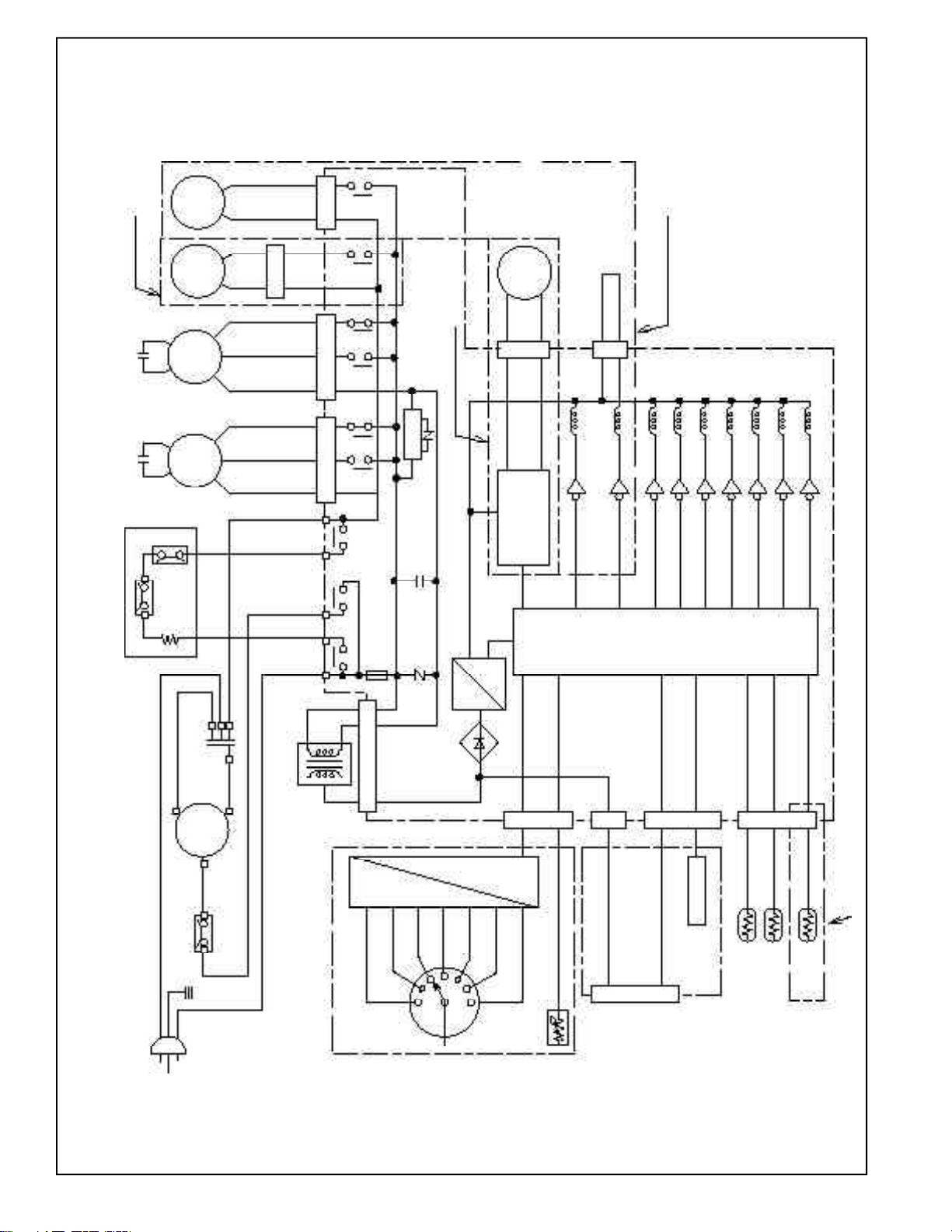
46
2200 and 3200 Series Typical
(HEATER UNIT)
HEATER
PROTECTOR
PROTECTOR
Running
Capacitor
Comp.
Motor
O.L.P.
R
Fan Motor
Capacitor
Outdoor
Fan
Motor
Fan Motor
Capacitor only AZ32H
Indoor
Fan
Motor
ICR
Pump
Reverse
Valve
Sol.
(TR1)
TRANSFORMER
RY2 RY1
RY3
FUSE
(FU1)
CN2
RY8
RY7
CN1
RY6
RY5
CN11
RY10
RY9
CN6
Varistor
(NR1)
CN8
Capacitor
(C2)
REGURATOR only AZ32H07/09
CONTROL BOARD
OPERATION BOARD
SELECT SW
HEAT H
HEAT L
OFF
FAN L
FAN H
COOL L
COOL H
THERMO CONTROL
DECODER
CN5
ID. COIL
only AZ32H
OD. COIL
ROOM
(for setting)
DIP SW
JUMPER
AUX BOARD
OPTIONAL
INTERFACE
UNIT
CN201
CN4
CN9
CN12
CONTROL
CIRCUIT
DC MOTOR
DRIVER
CN3 Reverse
Valve
Motor
BCN11
RY10
RY9
RY8
RY7
RY6
RY5
RY1
RY3
RY2
only AZ32H12/15
S
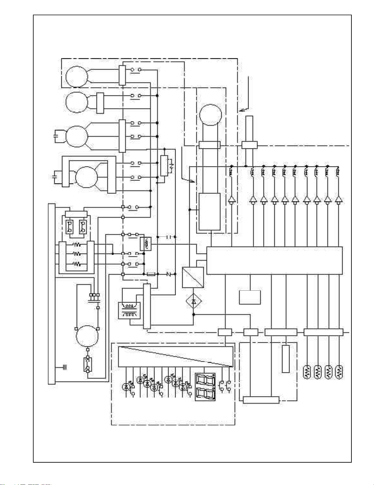
47
CONTROL CIRCUIT
(MAICRO COMPUTER etc.)
CN8
FUSE
(FU1)
CURRENT
DETECTOR (CT1)
PROTECTOR
PROTECTOR
Running
Capacitor
Comp.
Motor
O.L.P. C
UNIVERSAL CONNECTOR
Fan Motor
Capacitor
Outdoor
Fan
Motor
Fan Motor
Capacitor
Indoor
Fan
Motor
ICR
Pump
Reverse
Valve
Sol.
(TR1)
TRANSFORMER
RY4
RY2
RY1
RY7
RY3
RY6
RY8
CN1
CN6
Varistor
(NR1)
Capacitor
(C1)
REGURATOR only AZ52H07/09
OPERATION BOARD
OPERATION
OPERATION
COOL
FAN
HEAT
MODE
HIGH
LOW
AUTO
FAN SPEED
THERMO
UP
DOWN
DECODER
CN5
ID. COIL
ROOM
(for setting)
DIP SW
AUX BOARD
OPTIONAL
INTERFACE
UNIT
CN201
CN4
CN9
CN12
DC MOTOR
DRIVER
CN3
Reverse
Valve
Motor
BCN11
RY10
RY9
RY8
RY7
RY6
RY5
RY1
RY4
RY3
only AZ32H12/15
RY5
RY10
CN3
RY9
CONTROL BOARD
RY2
HEATER UNIT
HEATER
E
2
PROM
OD. COIL
HEATER
HEATER
R
S
OD. AIR
5200 Series Typical

49
Unit shall have means of electrical connection listed by
Underwriters Laboratories and compatible with the unit’s
ampacity which shall conform with National Electrical
Code
®
(NEC) and local codes.
[Internal Condensate Removal (“ICR”) system for Heat
Pump Units. Unit shall have a positive Internal
Condensate Removal (ICR) system to permit unit to
automatically dispose of heat pump generated
condensate with no overflow to outdoor to occur during
heating under outdoor ambient of 55°F. Dry Bulb, 90%
relative humidity; indoor ambient 70°F. Dry Bulb, 52%
Relative Humidity, for four hours of continuous run
time.]
[Condensate Drain System. To remove condensate from
the wall case an (internal) (external) drain adapter shall
be installed for connection to the building condensate
drain system as shown on the plans.]
Wall Case. (Wall case shall be constructed of heavy gauge,
zinc-coated, phosphatized steel, insulated and shall have a
protective baked-on enamel finish. Bottom critical points of
the steel wall case shall be treated with petroleum
microcrystalline wax for added corrosion protection and
shall meet ASTM B-117, 1800 hour hot air aerated salt spray
test.) (Wall case shall be constructed of a non-corroding
glass reinforced polyester compound.)
Cases shall be installed through exterior walls where shown
on the plans and shall be level from side to side and from
front to rear to ensure proper operation of condensate
system(s). They shall be secured to the wall at both sides
using nails or other appropriate fastening devices. In no
instance shall fasteners be used through the bottom in order
to retain the water integrity of the bottom of the
wall case.
Outside weather panels shipped with the cases shall remain
in place until the outdoor air louvers and chassis are
installed, at which time they are to be removed and
discarded by the installer.
[Sub-Base. Each unit shall have a field installed UL listed
electrical sub-base. The sub-base shall be attached to the
lower inside flange of the wall case prior to installation in
the exterior wall and shall include adjustable screws at the
bottom corners to permit exact leveling of the wall case. The
sub-base shall have side panels adjustable from a minimum
of 2 3/8" to a maximum of 13 3/4" to enclose the area
under the wall case.]
Outside Grille. Each unit shall be equipped with a standard
(Cycoloy
®
resin architectural) (extruded aluminum
architectural louvered) (stamped aluminum) grille that has
been designed to allow unit operation in high ambient
conditions.
Special grilles or customer louver sections to be supplied by
others will conform to minimum free area requirements for
unit performance and shall be submitted to the PTAC/
PTHP manufacturer, if requested, for feasibility and airflow
characteristics.
Room Cabinet. Each unit shall have a matching, easily
removable, textured finish, wrap-around roomside cabinet
molded of high temperature styrene to resist corrosion and
damage.
Optional Ducting. Units shown on the plans shall be ducted
using accessory duct adapters supplied by the manufacturer.
Duct extensions (supplied by the manufacturer) (field
supplied per the details on the plans) and shown ducted to
the right or left of the unit shall not exceed the maximum
length of 15 feet. Duct adapters and extensions shall have a
protective baked-on enamel and
1/2" of insulation wrapped around the interior of the duct
adapter and duct extension.
Weather Resistance. Complete unit including outside louver
shall be submitted to an independent agency for weather
resistance and water infiltration tests.
Air infiltration test to be conducted in accordance with
ASTM E283-91. With static air pressure differential of 1.57
lb./ft.
2
(.3" H
2
O) equivalent to 25 mph wind, allowable air
infiltration shall not exceed 7 ft.
3
/min. (Heat Pump units
with ICR may not exceed 10 ft.
3
/min.)
Water infiltration test to be conducted in accordance with
ASTM E331-86 with static air pressure differential of 10.0
lb./ft
2
(1.93" H
2
O) equivalent to 63 mph wind, 5.0 gal./ft.
2
(8" rain/ft.
2
/hr.) for 15 minutes and there shall be no
leakage into the room.
Approvals. Units shall be certified under the ARI and cUL
certification program and listed by UL.
Service. Submit complete information with bid covering
service availability, to whom service on units will be assigned,
complete address and phone number, including phone
number of emergency service personnel.
Start-Up, Adjust, Demonstrate. (Installing contractor)
(General contractor) shall be responsible for the initial
starting of units, adjustments thereto, etc., to place the units
in required operating condition. (Installing contractor)
(General contractor) shall demonstrate to the owner, or his
representative, the operation of units for both summer and
winter functions.
Warranty. The warranty shall be a full one year parts and
labor on entire unit plus an additional full four years parts
and labor for the sealed refrigerating system, including
service call for diagnosis, and transportation to and from
service shop, if necessary, at no charge to customer. The
warranty shall also include a limited 2nd thru 5th year parts
only warranty for fan motors, switches, thermostat, heater,
heater protectors, compressor overload, solenoids, circuit
boards, auxiliary controls, thermistors, Freeze Sentinel
TM
,
frost controls, ICR pump, capacitors, varistors, and indoor
blower bearing.
Installation Responsibility. Units shall be installed according
to the manufacturer
’
s recommendations and the
manufacturer shall not be responsible for unit failure as a
result of improper installation, or unit performance when
installed with accessories not approved by the manufacturer.

50
Suggested Bid Form
Specifications (Highly Featured
Microprocessor Control Units)
The following is a suggested specification for the GE Zoneline
5200 Series Packaged Terminal Heat Pump with
Microprocessor Controls
Items in brackets [ ] indicate optional items and should be
added to specifications if required. Items in parenthesis ( )
indicate one of the choices should be included in the
specifications.
The contractor will furnish Packaged Terminal (Air
Conditioners) (Heat Pumps) of the sizes and capacities
shown on the schedule and in the specifications. The units
shall be located as shown on the drawings and each shall
consist of a chassis, room cabinet, power connector kit, wall
case, [sub-base,] and outside grille.
Units shall be listed by UL, and ARI and cUL certified as to
capacity and efficiency and shall be GE Zoneline
®
models or
equal. Unit dimensions shall not exceed 42 1/8" wide and 16
1/4" high with room cabinet in place, [and 26 1/4" high with
duct adapter in place] and not more than 22 3/4" from face
of room cabinet to face of exterior grille.
Units shall be designed to operate on
volts, 60 Hz.,
single phase power.
Chassis. Unit (air conditioner) (heat pump) chassis shall be
the standard product of the manufacturer and shall be
shipped in protective cartons so as to preclude damage.
Cartons shall be appropriately marked at the factory with
wording sufficient to warn handlers against improper
stacking, up-ending, rolling or dropping.
Chassis shall be slide-in type, ready to operate after
installation.
Each shall consist of the following sections and components:
Hermetically-sealed refrigerant system with external
vibration isolated rotary-type compressor, condenser and
evaporator coils and capillary refrigerant control. Cooling
shall be possible to outdoor temperature of 35°F. without
damage to the compressor. Airflow system consisting of
one permanently lubricated two-speed fan motor for the
outdoor fan and a separate permanently lubricated two-
speed fan motor for the indoor fan. Outdoor fan shall be
multi-blade axial-flow design made of non-corrosive
material. Indoor fan shall be of a forward curved cross-flow
design. Only the indoor fan shall run during the heating
cycle on resistance heat models. All motors on the exterior
side of the weather barrier shall be of an enclosed design
to reduce the effects of moisture and corrosion.
A fan cycle switch to permit continuous indoor fan
operation or, to permit energy saving intermittent indoor
fan operation where the fan runs only when the
compressor or heater is operating.
A positive cooling condensate disposal system which meets
the test requirements of A.R.I. Standard 310-93 (80°F. dry
bulb, 75°F. wet bulb, 80% relative humidity) for Packaged
Terminal Air Conditioner units or A.R.I. Standards 380-93
(80°F. dry bulb, 75°F. wet bulb, 80% relative humidity) for
Packaged Terminal Heat Pump units;
Condenser and evaporator coils to be constructed of
copper tubing and aluminum plate fins with
enhancements necessary to achieve EER and COP rating
of the unit;
Indoor and outdoor airflows that match the capacity of
the coils for efficient heat transfer. Water blow-off shall
not occur on the indoor coil;
Adjustable indoor discharge air louvers that provide a 45°
off vertical air pattern with an alternate position to
provide a 30° off vertical air pattern;
Easily accessible controls for unit Operation and
Thermostat setting. Controls shall be covered by a hinged
door;
Slide-out washable filters accessible from top of unit
without requiring removal of room cabinet;
Positive closing fresh air damper located within the
chassis operated by concealed manual control;
Thermistor temperature sensing device to measure room
temperature and control operation of unit;
Electronic temperature limiting, to permit 7 independent
heating limits and 7 independent cooling limits;
Freeze Sentinel
TM
to automatically activate the electric
resistance heater and fan motor to warm and circulate
indoor air to help prevent damage due to freezing
temperatures. Freeze Sentinel
TM
shall operate as long as
unit is connected to powered electrical circuit;
Compatible with 2 wire Central Desk Control; (RAKOIM
required)
Compatible with Class 2 Remote Thermostat Control
utilizing (GE thermostat model RAK147 for Packaged
Terminal Heat Pump). (RAKOIM required)
[Heat pumps]
Heat pump units shall provide a choice of operation that
will allow either: A) automatically phase-in partial electric
resistance heat, if outdoor temperature is below 46°F.,
simultaneously with heat pump if heat pump alone is
unable to maintain room temperature; or B) partial
electric resistance heat simultaneous with heat pump
operation any time the outdoor temperature is below
45°F. Selection of A or B operation is made by means of a
selector switch concealed from room occupant. In either
A or B operation the unit will switch to full resistance
heat if room temperature continues to decline or the
outdoor temperature falls below 25°F. If the outdoor
temperature is above 46°F., unit will lock-out electric
resistance heat and operate on heat pump only. Unit
shall have a switch concealed from room occupant to
allow heat pump operation to be overridden and heat
provided by electric resistance heat regardless of outdoor
temperature.

51
Heat pump unit shall include Reverse Cycle Defrost that
automatically begins a defrost cycle when microprocessor
determines criteria for defrosting has been met.
Defrosting shall be accomplished by systematically
ceasing heat pump operation, pausing to allow internal
refrigerant pressures to equalize, then operating the
compressor with the flow of refrigerant reversed, to allow
the hot gas to flow through the outdoor coil melting the
accumulated frost. Unit shall automatically resume heat
pump operation, after pausing to allow refrigerant
pressures to equalize, at conclusion of defrost cycle.
In the event of compressor failure during heat pump
operation, unit shall automatically switch to electric
resistance heat to maintain selected room temperature
regardless of outdoor temperatures.
Unit shall have means of electrical connection listed by
Underwriters Laboratories and compatible with the unit’s
ampacity which shall conform with National Electrical
Code
®
(NEC) and local codes.
[Internal Condensate Removal (ICR) system for Heat
Pump Units. Unit shall have a positive Internal Condensate
Removal (ICR) system to permit unit to automatically
dispose of heat pump generated condensate with no
overflow to outdoor to occur during heating under outdoor
ambient of 55°F. Dry Bulb, 90% relative humidity; indoor
ambient 70°F. Dry Bulb, 52% Relative Humidity, for four
hours of continuous run time.]
[Condensate Drain System. To remove condensate from
the wall case an (internal) (external) drain adapter shall
be installed for connection to the building condensate
drain system as shown on the plans.]
Wall Case. (Wall case shall be constructed of heavy gauge,
zinc-coated, phosphatized steel, insulated and shall have a
protective baked-on enamel finish. Bottom critical points of
the steel wall case shall be treated with petroleum
microcrystalline wax for added corrosion protection and
shall meet ASTM B-117, 1800 hour hot air aerated salt spray
test. (Wall case shall be constructed of a non-corroding glass
reinforced polyester compound.)
Cases shall be installed through exterior walls where shown
on the plans and shall be level from side to side and from
front to rear to ensure proper operation of condensate
system(s). They shall be secured to the wall at both sides
using nails or other appropriate fastening devices. In no
instance shall fasteners be used through the bottom in order
to retain the water integrity of the bottom of the
wall case.
Outside weather panels shipped with the cases shall remain
in place until the outdoor air louvers and chassis are
installed, at which time they are to be removed and
discarded by the installer.
[Sub-Base. Each unit shall have a field installed UL listed
electrical sub-base. The sub-base shall be attached to the
lower inside flange of the wall case prior to installation in
the exterior wall and shall include adjustable screws at the
bottom corners to permit exact leveling of the wall case. The
sub-base shall have side panels adjustable from a minimum
of 2 3/8" to a maximum of 13 3/4" to enclose the area
under the wall case.]
Outside Grille. Each unit shall be equipped with a standard
(Cycoloy
®
resin architectural) (extruded aluminum
architectural louvered) (stamped aluminum) grille that has
been designed to allow unit operation in high ambient
conditions.
Special grilles or customer louver sections to be supplied by
others will conform to minimum free area requirements for
unit performance and shall be submitted to the PTAC/
PTHP manufacturer, if requested, for feasibility and airflow
characteristics.
Room Cabinet. Each unit shall have a matching, easily
removable, textured finish, wrap-around roomside cabinet
molded of high temperature styrene to resist corrosion
and damage.
Weather Resistance. Complete unit including outside louver
shall be submitted to an independent agency for weather
resistance and water infiltration tests.
Air infiltration test to be conducted in accordance with
ASTM E283-91. With static air pressure differential of 1.57
lb./ft.
2
(.3" H
2
O) equivalent to 25 mph wind, allowable air
infiltration shall not exceed 7 ft.
3
/min.
Water infiltration test to be conducted in accordance with
ASTM E331-86 with static air pressure differential of 10.0
lb./ft
2
(1.93" H
2
O) equivalent to 63 mph wind, 5.0 gal./ft.
2
(8" rain/ft.
2
/hr.) for 15 minutes and there shall be no
leakage into the room.
Approvals. Units shall be certified under the ARI and cUL
certification program and listed by UL.
Service. Submit complete information with bid covering
service availability, to whom service on units will be assigned,
complete address and phone number, including phone
number of emergency service personnel.
Start-Up, Adjust, Demonstrate. (Installing contractor)
(General contractor) shall be responsible for the initial
starting of units, adjustments thereto, etc., to place the units
in required operating condition. (Installing contractor)
(General contractor) shall demonstrate to the owner, or his
representative, the operation of units for both summer and
winter functions.
Warranty. The warranty shall be a full one year parts and
labor on entire unit plus an additional full four years parts
and labor for the sealed refrigerating system, including
service call for diagnosis, and transportation to and from
service shop, if necessary, at no charge to customer. The
warranty shall also include a limited 2nd thru 5th year parts
only warranty for fan motors, switches, thermostat, heater,
heater protectors, compressor overload, solenoids, circuit
boards, auxiliary controls, thermistors, Freeze Sentinel
TM
,
frost controls, ICR pump, capacitors, varistors, and indoor
blower bearing.
Installation Responsibility. Units shall be installed according
to the manufacturer’s recommendations and the
manufacturer shall not be responsible for unit failure as a
result of improper installation, or unit performance when
installed with accessories not approved by the manufacturer.
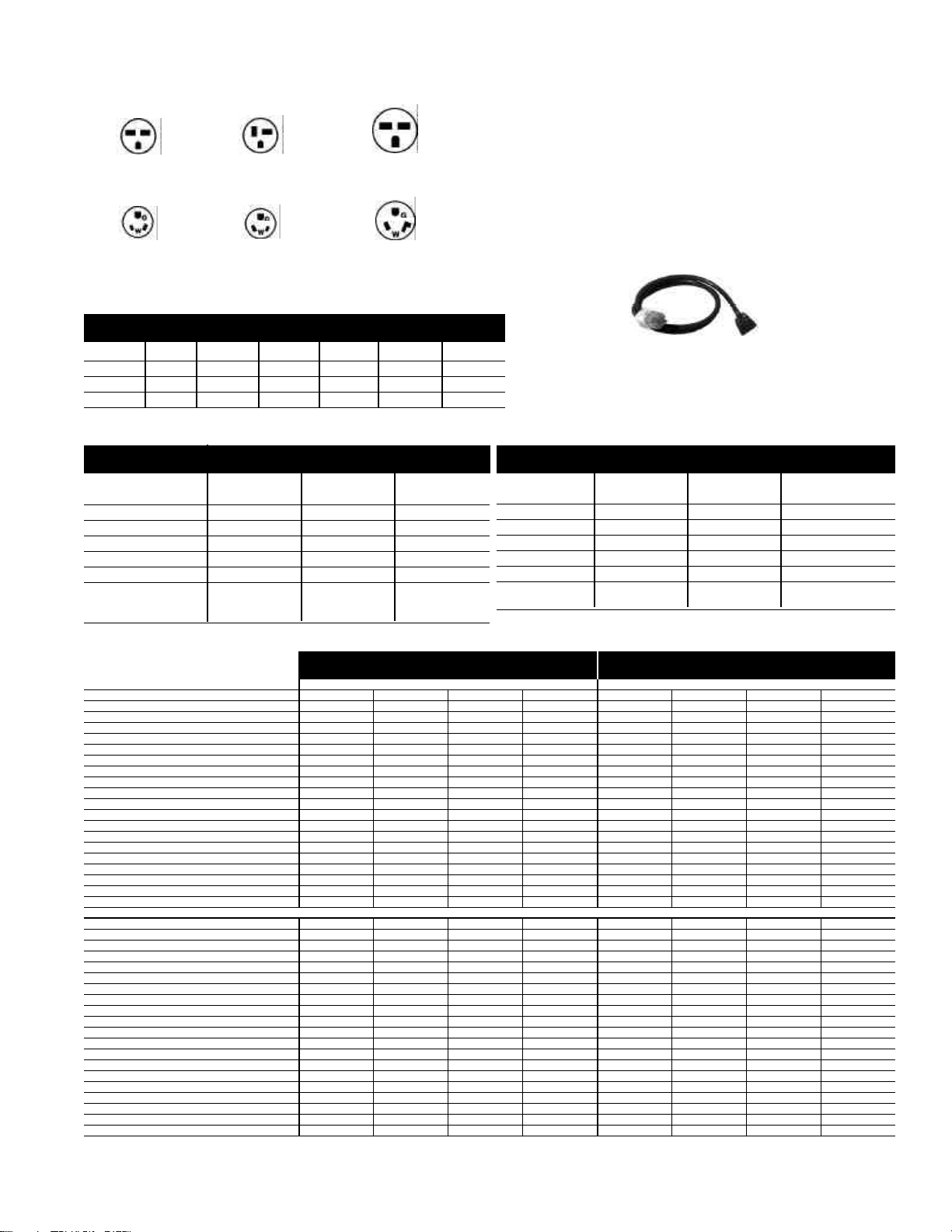
53
RAK3152/3202/3302
230/208 volt Line Cord Connection Kit
Receptacles/Sub-Bases
Perpendicular
230/208V 20 Amp
NEMA6-20R
Tandem
230/208V 15 Amp
NEMA6-20R
Large Tandem
230/208V 30 Amp
NEMA6-30R
265V 15 Amp
NEMA7-15R;
receptacle used on
265V sub-base
GEO715
265V 20 Amp
NEMA7-20R;
receptacle used on
265V sub-base
GEO720-3
265V 30 Amp
NEMA7-30R;
receptacle used on
265V sub-base
GEO73
Power Connection Kits - Required on premium models. See
specification sheet for heater KW and branch circuit ampacity.
Premium Line: 5200 Series - Power Connection Kits
are REQUIRED on Premium Zoneline Chassis. (see chart below)
The correct kit for the installation is determined by the voltage and
amperage of the electrical circuit and the means of connecting the
unit to the building wiring. If the unit is to be plugged into a
receptacle, a line cord kit would be used; if the unit is to be
permanently connected, a permanent connection kit would be used.
265 volt cord set units must be installed in compliance with National
Electrical Code.¨
230/208 Volt
Power Connection
Kit
Heater KW
Watts
BTUH
Amps
Min. Circuit Amps
Recommended
Protective
Device
Line Cord Connected Units
RAK3152 RAK3202 RAK3302
2.55/2.09 3.45/2.82 5.00/4.09
2,550/2,090 3,450/2,820 5,000/4,090
8,600/7,100 11,700/9,600 17,000/13,900
11.1/10.0 15.0/13.6 21.7/19.7
15 20 30
15 Amp 20 Amp 30 Amp
Time Delay Time Delay Time Delay
Fuse or Breaker Fuse or Breaker Fuse or Breaker
265 Volt
Permanent Connected Units**
(Cord Set)
RAK5152 RAK5172 RAK5202 RAK5302
1.7 3.0 3.7 5.0
1,700 3,000 3,700 5,000
5,800 10,200 12,600 17,000
6.4 11.3 14.0 18.9
15 15 20 30
15 Amp 15 Amp 20 Amp 30 Amp
Time Delay Fuse Time Delay Fuse Time Delay Fuse Time Delay Fuse
**To Be Used With Sub-base
3200 Series Units 5200 Series Units
230/208V Models AZ32H07D AZ32H09D AZ32H12D AZ32H15D AZ52H07D AZ52H09D AZ52H12D AZ52H15D
Capacity
Cooling BTUH 7,100/6,900 9,000/8,800 11,700/11,500 14,600/14,300 7,100/6,800 9,000/8,800 11,800/11,600 14,700/14,400
EER (BTU/Watt) 11.6/11.6 11.3/11.3 10.7/10.7 9.6/9.6 12.0/12.0 11.3/11.3 10.7/10.7 10.0/10.0
Dehumidification Pts/Hr 1.7 2.7 3.6 4.5 1.7 2.8 3.6 4.8
Features
CFM, Indoor Fan High 250 260 280 310 240 290 330 350
CFM, Indoor Fan Low 220 230 250 280 220 270 310 330
Vent CFM 40/35 65/60 70/65 70/65 40/35 65/60 70/65 70/65
Power/Ratings
Power Factor 95 96 97 94 95 96 94 95
Sensible Heat Ratio @ 230 Volts 75% 68% 67% 67% 75% 67% 68% 65%
Watts 610/595 795/780 1095/1075 1520/1490 590/565 795/780 1105/1085 1470/1440
Amperes, F.L. 2.8/3.0 3.6/3.9 4.9/5.3 7.0/7.5 2.7/2.9 3.6/3.9 5.1/5.5 6.7/7.3
Amperes, L.R. 19.0 21.0 33.0 38.0 19.0 21.0 33.0 38.0
Reverse Cycle Heat BTUH 6400/6200 8400/8200 10900/10700 13400/13200 6,400/6,200 8,400/8,200 10,900/10,700 13,400/13,200
COP 3.5/3.5 3.5/3.5 3.3/3.3 3.1/3.1 3.5/3.5 3.5/3.5 3.3/3.3 3.1/3.1
Watts 535/520 705/685 970/950 1265/1250 535/520 700/685 970/950 1,265/1,250
Amps 2.4/2.6 3.1/3.4 4.3/4.7 5.8/6.3 2.4/2.6 3.1/3.3 4.3/4.7 5.8/6.3
Weight (Ship/Net)** 125/109 127/111 131/121 145/129 129/104 122/106 132/116 143/127
265V Models AZ32H07E AZ32H09E AZ32H12E AZ32H15E AZ52H07E AZ52H09E AZ52H12E AZ52H15E
Capacity
Cooling BTUH 7,100 9,000 11,700 14,600 7,100 9,000 11,800 14,700
EER (BTU/Watt) 11.6 11.3 10.7 9.6 12.0 11.3 10.7 10.0
Dehumidification Pts/Hr 1.7 2.7 3.6 4.5 1.7 2.8 3.6 4.8
Features
CFM, Indoor Fan High 250 260 280 310 240 290 330 350
CFM, Indoor Fan Low 220 230 250 280 220 270 310 330
Vent CFM 40 65 70 70 40 65 70 70
Power/Ratings
Power Factor 96 94 94 96 97 94 93 96
Sensible Heat Ratio @ 265 Volts 75% 68% 67% 67% 75% 67% 68% 65%
Watts 610 795 1095 1520 590 795 1105 1470
Amperes, F.L. 2.4 3.2 4.4 6.0 2.3 3.2 4.5 5.8
Amperes, L.R. 16.0 18.0 24.0 31.0 16.0 18.0 24.0 31.0
Reverse Cycle Heat BTUH 6,400 8,400 11,900 13,400 6,400 8,400 10,900 13,400
COP 3.5 3.5 3.3 3.1 3.5 3.5 3.3 3.1
Watts 535 700 970 1265 535 700 970 1,265
Amps 2.2 2.8 3.9 5.0 2.2 2.7 3.9 5.0
Weight (Ship/Net)** 125/109 127/111 131/121 145/129 120/104 122/106 132/116 143/127
** ICR adds 3 pounds to unit weight
Deluxe Series - Heat Pump Units Premium Series - Heat Pump Units
Sub-bases
RAK204U RAK204D20 RAK204D30 RAK204E15 RAK204E20 RAK204E30
Voltage N/A 230/208 230/208 265 265 265
Amps N/A 15/20 30 15 20 30
Receptacle N/A NEMA6-20R NEMA6-30R NEMA7-15R NEMA7-20R NEMA7-30R
265 Volt units are to be direct connected. Cordset through enclosed chaseway
into interior sub-base receptacle meets the NEC requirements.

54
Maximum Connected Load For
Deluxe Series (2200 and 3200)
The maximum connected load of a Zoneline occurs when
the unit is in resistance heating operation. The maximum
amperage shown in the tables below is the combined total of
the resistance heater and the fan motor.
In the tables below, the heater designator in the model
number is represented by an “*” in the model number
column. To find the maximum connected load, locate the
model in the left column and go across the row to the
column headed by the 9th character in the model number
or the heater watts.
The sum of the fan motor requirements TABLE A and the
heater requirements TABLE B equal the Maximum
Connected Load of the unit.
Heating Operation - Resistance Heater Electrical Data
Table B - 230/208 Volt Units
Model Number * = 2 * = 3 * = 5
Watts Amps Watts Amps Watts Amps
AZ22E07D*C 2550 11.1 3450 15.0 – –
AZ22E09D*C 2550 11.1 3450 15.0 5000 21.7
AZ22E12D*C 2550 11.1 3450 15.0 5000 21.7
AZ22E15D*C 2550 11.1 3450 15.0 5000 21.7
AZ32H07D*C / D*D 2550 11.1 3450 15.0 5000 21.7
AZ32H09D*C / D*D 2550 11.1 3450 15.0 5000 21.7
AZ32H12D*C / D*D 2550 11.1 3450 15.0 5000 21.7
AZ32H15D*C / D*D 2550 11.1 3450 15.0 5000 21.7
230 Volt
Heater Watts - 2550 Heater Watts - 3450 Heater Watts - 5000
Model Number * = 2 * = 3 * = 5
Watts Amps Watts Amps Watts Amps
AZ22E07D*C 2090 10.0 2820 13.6 – –
AZ22E09D*C 2090 10.0 2820 13.6 4090 19.7
AZ22E12D*C 2090 10.0 2820 13.6 4090 19.7
AZ22E15D*C 2090 10.0 2820 13.6 4090 19.7
AZ32H07D*C / D*D 2090 10.0 2820 13.6 4090 19.7
AZ32H09D*C / D*D 2090 10.0 2820 13.6 4090 19.7
AZ32H12D*C / D*D 2090 10.0 2820 13.6 4090 19.7
AZ32H15D*C / D*D 2090 10.0 2820 13.6 4090 19.7
208 Volt
Heater Watts - 2090 Heater Watts - 2820 Heater Watts - 409
0
Model Number Fan Motor- 230 Volts Fan Motor- 208 Volts Model Number Fan Motor - 265 Volts
Outdoor Fan Motor Electrical Data For Deluxe 2200 & 3200 Series
Two Fan Motor Models
For Information Only. Do Not Include In Maximum Connected Load Calculations.
Watts Amps Watts Amps Watts Amps
AZ*2H07DAB/DAD 65 0.3 60 0.3 AZ*2H07EAB/EAD 75 0.3
AZ*2H09DAB/DAD 65 0.3 60 0.3 AZ*2H09EAB/EAD 75 0.3
AZ*2H12DAB/DAD 90 0.4 80 0.4 AZ*2H12EAB/EAD 100 0.4
AZ*2H15DAB/DAD 135 0.6 125 0.6 AZ*2H15EAB/EAD 135 0.5
Heater Watts - 2000 Heater Watts - 3000 Heater Watts - 4000 Heater Watts - 5000
Table B - 265 Volt Units
Model Number * = 2 * = 3 * = 4 * = 5
Watts Amps Watts Amps Watts Amps Watts Amps
AZ22E07E*C 2000 7.6 3000 11.3 4000 15.1 – –
AZ22E09E*C 2000 7.6 3000 11.3 4000 15.1 5000 18.9
AZ22E12E*C 2000 7.6 3000 11.3 4000 15.1 5000 18.9
AZ22E15E*C 2000 7.6 3000 11.3 4000 15.1 5000 18.9
AZ32H07E*C / E*D 2000 7.6 3000 11.3 4000 15.1 5000 18.9
AZ32H09E*C / E*D 2000 7.6 3000 11.3 4000 15.1 5000 18.9
AZ32H12E*C / E*D 2000 7.6 3000 11.3 4000 15.1 5000 18.9
AZ32H15E*C / E*D 2000 7.6 3000 11.3 4000 15.1 5000 18.9
265 Volt
Model Number 230 V 208 V
Watts Amps Watts Amps
AZ22E07D*C 50 0.22 40 0.20
AZ22E09D*C 60 0.27 50 0.25
AZ22E12D*C 70 0.31 60 0.30
AZ22E15D*C 80 0.36 70 0.35
AZ32H07D*C / D*D 50 0.22 40 0.20
AZ32H09D*C / D*D 60 0.27 50 0.25
AZ32H12D*C / D*D 70 0.31 60 0.30
AZ32H15D*C / D*D 80 0.36 70 0.35
Table A - 230/208 Volt Units
230 Volt
Heating Operation - Indoor Fan Motor Electrical Data
Table A - 265 Volt Units
Model Number 265 V
Watts Amps
AZ22E07E*C 50 0.19
AZ22E09E*C 60 0.22
AZ22E12E*C 70 0.26
AZ22E15E*C 80 0.30
AZ32H07E*C / E*D 50 0.19
AZ32H09E*C / E*D 60 0.22
AZ32H12E*C / E*D 70 0.26
AZ32H15E*C / E*D 80 0.30
265 Volt

57
Replacement of Existing Heat/
Cool Zoneline or Similar Unit
Is the existing unit GE or other manufacture?
• GE model number ___________
• Air conditioner model number and brand
(other than GE) ___________
• Capacity ____ Voltage ____ Amp ____ Other ____
COOLING
Should a change in unit BTU cooling or heating be
considered?
• Did the existing unit cool the room quickly on a hot day?
And cycle OFF/ON thermostat on the hottest day. This is
an indication that unit is larger capacity than required
• Is the room being remodeled and any of the following
changed.
– Changing the windows from single pane to double or
triple pane design. Tinting, low e glass etc.?
– Are windows being made smaller?
– Is insulation being added to outside wall?
– Room vent air being changed?
• Should engineering calculations be made to determine
BTUs necessary for cooling and heating?
• When engineering calculations are made to determine the
correct BTU size for cooling operation, a smaller BTU
model is often recommended. A smaller BTU model will
run longer to cool the room but less power (KWH) will be
used. Money is saved when less KWH (kilowatt hours) are
consumed.
– Smaller BTU models are generally quieter during
cooling and heating operations.
– With the smaller BTU model running longer the
room is generally less humid. Humidity control is very
important in the warm humid areas, and normally
guests will be more comfortable in rooms with lower
humidity.
WALL CASE
• New GE model will install into existing GE Zoneline wall
case. (First Zoneline made in 1961) (Consider using wall
case insulation RAK901L in existing wall cases.)
• Zoneline may fit into existing competitive wall case. (If
wall case extends into room and is not insulated consider
using insulation kit RAK901L)
• If a case extension is used on the existing wall cases, the air
splitters installed in these case extensions must mate and
seal to the ends of the outdoor coil of the new unit. This
may require moving the splitters.
OUTDOOR GRILLE
• Existing outdoor grille may need to be changed or
modified when an old chassis is replaced. Outdoor air flow
patterns have changed and this may dictate the need for
outdoor grille replacement or modification.
SAVINGS
• New unit with higher EER (Energy Efficiency Ratio) than
older existing unit should provide energy savings.
Calculations can be made to estimate annual savings.
• Reduce demand charges with high efficiency models.
• Some utility companies may offer rebates/incentives for
installing heat pump models - check with serving utility
company.
• When engineering calculations are made to determine the
correct BTU size for cooling operation, a smaller BTU
model is often recommended as the replacement model.
A smaller BTU model will run longer to cool the room but
less power (KWH) is used. Money is saved when less KWH
(kilowatt hours) are consumed.
– Smaller BTU models are generally quieter during
cooling and heating operation.
– With the smaller BTU model running longer, the
room is generally less humid. Humidity control is very
important in the warm humid areas.
HEATING
In most areas of the U.S.A., the greatest operational costs are
in heating operation. Analyzing the cost of heating with a
heat pump vs electric heat may show strong incentives to
replace older electric heat models with new higher efficiency
heat pump models. Seasonal performance (SPF) reports
can be provided to estimate the annual savings. Contact
your General Electric (Zoneline) sales person to obtain
this report.
OTHER POSSIBLE SAVINGS
– Minimize the electrical total connected load (use
correct heater size).
– Reduce demand charges using heat pump models
with the proper electric heater size and resistance
heat lockout, and heat pump operation to approx.
25°F.

59
Exterior Grille Color Samples
Colors may vary slightly due to printing process.
RAG63 RAG66 Bittersweet Chocolate
RAG62 RAG65 Maple
RAG61 RAG64 Warm Gray Beige
Equipment used as a primary source for heating or cooling is an integral part of the building in which it is installed. Proper application is
essential for satisfactory performance over a wide range of operating conditions. It is strongly recommended that a professional engineer
determine proper application.
If this unit is a replacement unit, its specifications and performance may differ from those of the unit it is replacing. For that reason, we
again strongly recommend that a professional engineer determine proper application. See page 42.
GE has a policy of continuous improvement on its products and reserves the right to change materials and specifications without notice.
Listed by
Underwriters’
Laboratories.
Pub. No. 20-SO29
OTT1317 5/99
g
GE Appliances
General Electric Company
Louisville, Kentucky 40225
ZONELINE
WARRANTY
WHAT IS COVERED
Staple sales slip or cancelled check here. Proof of original
purchase date is needed to obtain service under warranty.
For service in the U.S., call 800-GE-CARES. In Canada,
contact: Manager, Consumer Relations, Camco Inc., 5800
Keaton Crescent, Mississauga, Ontario, Canada L5R 3K2.
FULL ONE-YEAR WARRANTY
For one year from date of original purchase, we
will provide, free of charge, parts and service labor
on site to repair or replace any part of the Zoneline
that fails because of a manufacturing defect.
FULL FIVE-YEAR WARRANTY
For five years from the date of original purchase,
we will provide, free of charge, parts and on-site
service labor to repair or replace any part of the
sealed refrigerating system (the compressor,
condenser, evaporator and all connecting tubing)
that fails because of a manufacturing defect.
®
Warrantor: General Electric Company. Louisville, KY 40225
This warranty is extended to the original purchaser and any succeeding owner for products purchased for use
within the USA and Canada. In Alaska, the warranty excludes the cost of shipping or service calls to your site.
Some states do not allow the exclusion or limitation of incidental or consequential damages. This warranty gives
you specific legal rights, and you may also have other rights which vary from state to state. To know what your
legal rights are in your state, consult your local or state consumer affairs office or your state’s Attorney General.
LIMITED 2ND THROUGH
5TH YEAR PARTS WARRANTY
For the second through the fifth year from date
of original purchase, General Electric will
provide, free of charge, parts that fail as a result
of a manufacturing defect. Parts covered are
fan motors, switches, thermostat, heater, heater
protectors, compressor overload, solenoids,
circuit boards, auxiliary controls, thermistors,
Freeze Sentinel, frost controls, ICR pump,
capacitors, varistors, and indoor blower
bearing. This is a limited parts-only warranty,
and does not include labor or transportation to
and from the service shop.
All warranty service will be provided by our
Factory Service Centers or by our authorized
Customer Care
®
servicers during normal
working hours.
WHAT IS NOT COVERED
• Service trips to your site to teach you how to
use the product.
• Improper installation.
If you have an installation problem, or if the
air conditioner is of improper cooling capacity
for the intended use, contact your dealer or
installer. You are responsible for providing
adequate electrical connecting facilities.
• Replacement of fuses or resetting of circuit
breakers.
• In commercial locations, labor necessary to
move the unit to a location where it is
accessible for service by an individual
technician.
• Failure of the product resulting from
modifications to the product or due to
unreasonable use including failure to provide
reasonable and necessary maintenance.
• Failure or damage resulting from corrosion
due to installation in an environment
containing corrosive chemicals.
• Failure or damage resulting from corrosion
due to installation in a coastal environment,
except for models treated with special
factory-applied anti-corrosion protection as
designated in the model number.
• Damage to product caused by improper
power supply voltage, accident, fire, floods or
acts of God.
• Incidental or consequential damage to
personal property caused by possible defects
with this air conditioner.