Loading ...
Loading ...
Loading ...
33
4-WIRE CONDUIT INSTALLATION
NOTE: ALUMINUM WIRING:
Aluminum building wire may be used but it
must be rated for the correct amperage and
voltage to make connection. Connect wires
according to this step depending on number
of wires.
A. Remove the screws and raise the terminal
block cover (lower part of the back wire cover).
B. Remove the three aluminum connectors and
ground plate attached to the back of the range.
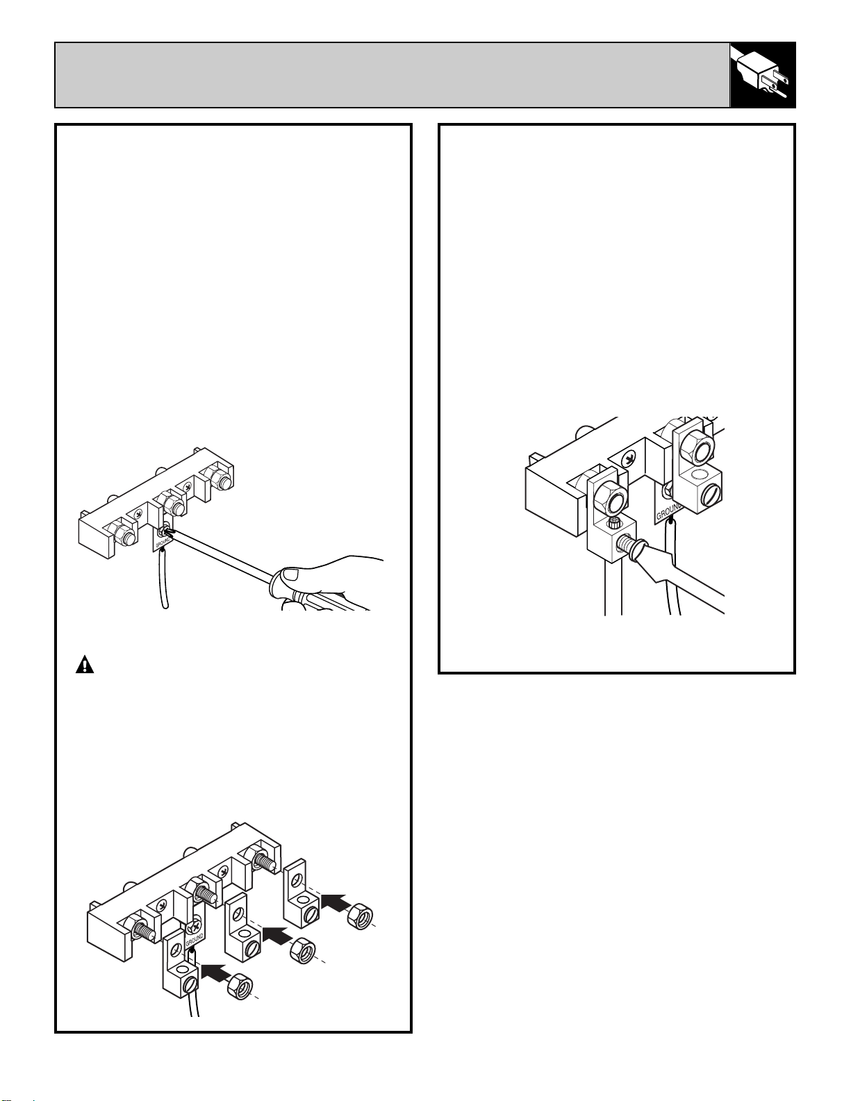
C. Remove the ground strap from the terminal
block and from the appliance frame. Retain the
ground screw.
D. Insert the ground bare wire tip between the
range frame and the ground plate and secure it
in place with the ground screw (removed earlier).
E. Remove the three outer terminal nuts from
the terminal block.
WARNING:
DO NOT loosen any
of the inside nuts on the terminal block.
Electrical failure, loss of electrical
connection, electrical shock or fire may
result causing property damage, personal
injury or death.
F. Using the outer nuts removed from the
appliance terminal block, secure the connectors
to all three of the terminals.
4-WIRE CONDUIT INSTALLATION (cont.)
G. Insert the center bare wire (neutral) tip
through the bottom opening of the center
connector. Insert the two side bare wire tips into
the bottom openings in the left and the right
connectors. Tighten each screw to secure the
aluminum wires.
Torque Requirements
Aluminum Connector to Terminal Block:
• 20 in./lbs.
Copper & Aluminum Wire to Connector:
• 10–14 ga. – 20 in./lbs.
• 8 ga. – 25 in./lbs.
• 6 ga. – 35 in./lbs.
H. Replace the terminal block cover.
(continued next page)
Loading ...
Loading ...
Loading ...