Loading ...
Loading ...
Loading ...
15
Remote Thermostat Control
In some installations, control of the
operation of the unit at a location
remote to the unit itself may be desired.
Unit mounting locations (high in the
wall or over a transom) resulting in
inaccessible unit mounted controls can
be connected to a remote thermostat.
Other installations may use remote
thermostat control for design or
performance enhancement. The unit is
connected to the thermostat by low voltage wiring, which
permits the operation of the unit to be selected and the
temperature to be sensed at the thermostat.
All Zoneline 2500, 3500 and 5500 Series units are adaptable
to Class 2 remote low voltage thermostat. The only
additional field supplied components are the remote
thermostat and wiring necessary to connect it.
The controls on the unit are not functional when the remote
control function is used.
Resistance Heat Models
The Zoneline 2500 resistance heat units may be connected
to a single-stage thermostat designed for use with cooling
with electric heat systems. GE offers 3 thermostats
compatible with the 2500 series unit.
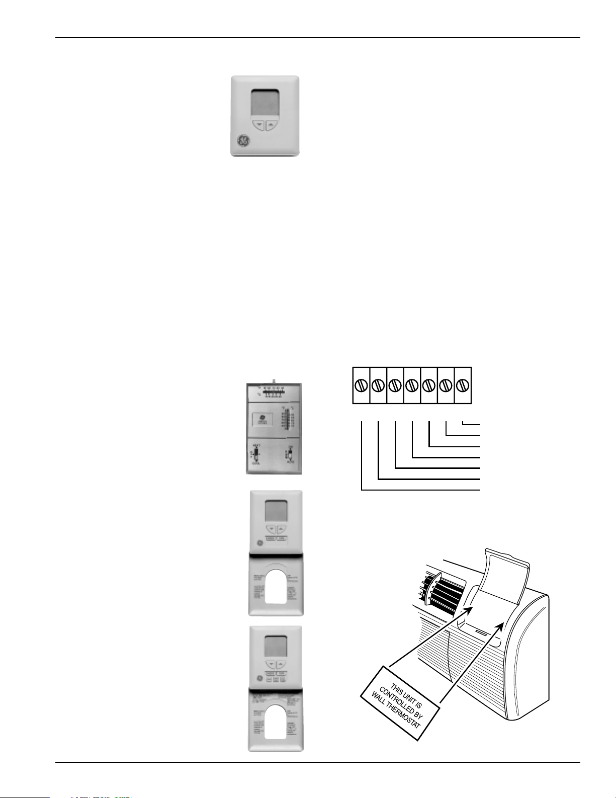
RAK163A1 - a mechanical manual
changeover thermostat requiring 4
connection wires.
RAK163D1 - a solid state digital manual
changeover thermostat requiring 5
connection wires.
RAK163P1 - a solid state digital
programmable auto changeover thermostat
requiring 5 connection wires.
The Class 2 Mode Switch (dip switch 12 on the auxiliary
control board) must be set to the ON/UP mode to enable
remote thermostat control. Refer to installation instructions
packaged with the chassis.
Please see page 57 for installation recommendations for the
remote thermostat wiring.
Compatibility of other thermostats considered for use with
the GE Zoneline unit is the responsibility of the customer.
The control voltage on the remote control conductors is
24 VAC. The units may not be compatible with some solid
state thermostats.
The fan speed for the 2500 series in remote thermostat
operation is selected by the connection of the fan wire from
the thermostat to either the HIGH or LOW terminal on the
unit. See the sketch of the unit terminals for the location of
the HIGH and LOW fan speed terminals. Operating in low
fan speed reduces the operating sound level of the unit.
Freeze Sentinel
TM
remains operational if the unit is
connected to a remote thermostat. The unit may be
connected to a Central Desk Control (CDC) system and
controlled with a remote thermostat when the CDC system
has the unit in an operational status. See page 14 for
additional information on the CDC system.
R
GL
GH
B
Y
W
C
Common - Ground
White - Heater
Yellow - Compressor
Black - Not Used On 2500
Green - High Speed Fan
Green - Low Speed Fan
Red - 24 VAC
(shown closed)
2020 Data Manual 2002 11/7/02 3:19 PM Page 15
Loading ...
Loading ...
Loading ...