Loading ...
Loading ...
Loading ...
16
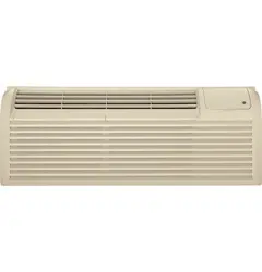
Remote Thermostat Control
Heat Pump Models
The Zoneline
®
3800 and 5800 Series heat pump units may
be connected to a single-stage cooling/two-stage heating
thermostat designed for use with heat pump systems. GE
offers 3 thermostats compatible with the 3800 and 5800
series units:
RAK147 —
mechanical
manual
changeover
thermostat
requiring 6
connection wires.
RAK148D1 —
solid-state digital
manual
changeover
thermostat
requiring 6
connection wires.
RAK148P1 —
solid-state digital
programmable
auto-changeover
thermostat
requiring 6
connection wires.
Please see page 57 for installation recommendations for the
remote thermostat wiring. Compatibility of other thermostats
considered for use with the GE Zoneline
®
is the responsibility
of the customer.
The control voltage on the remote control conductors is 24 VAC.
The Class 2 Mode Switch, dip switch #4 on the auxiliary control
board on both the 3800 series and the 5800 series, must be set
to the ON/UP mode to enable remote thermostat control. Refer
to installation instructions packaged with the chassis.
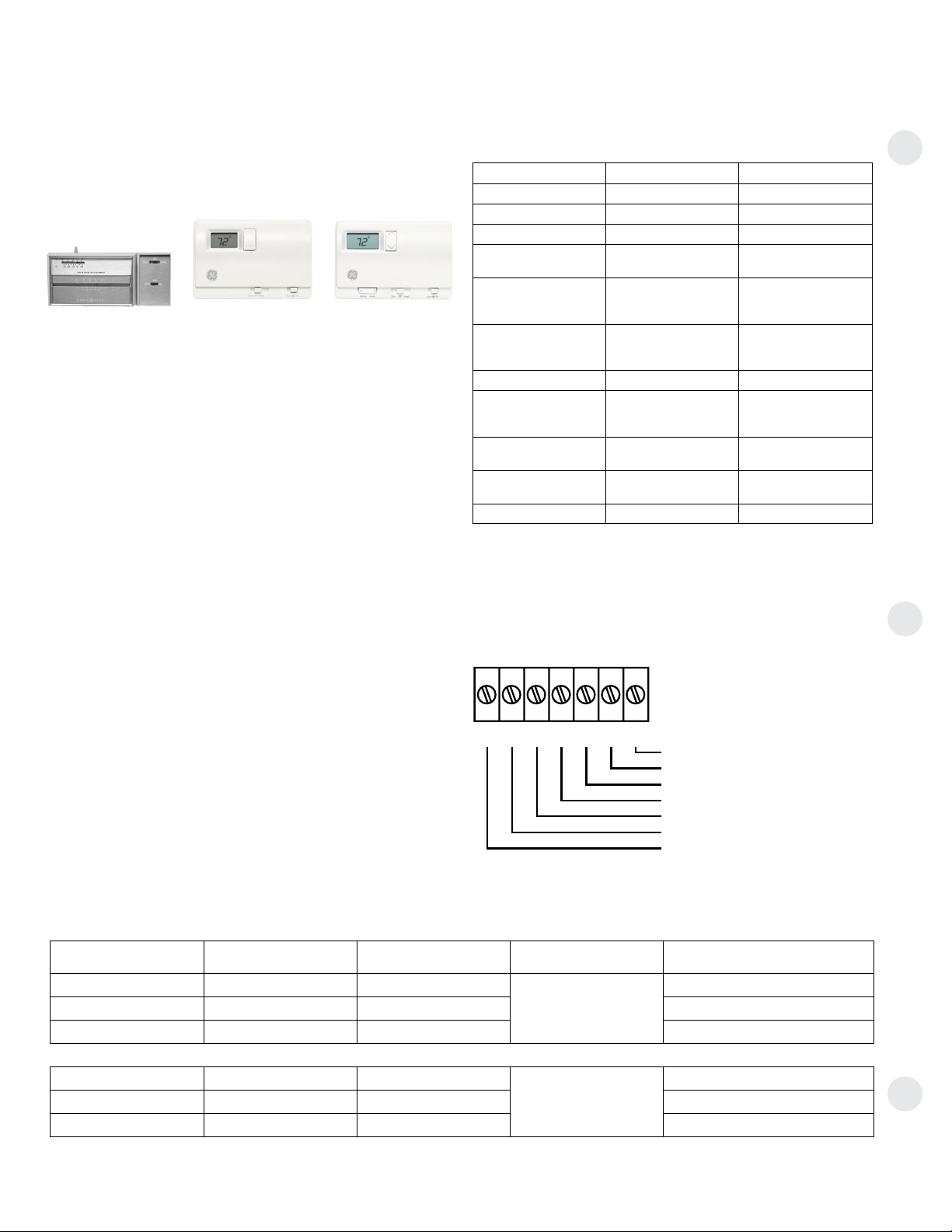
The fan speed for the 3800 and 5800 series in remote
thermostat operation is selected by the connection of the
fan wire from the thermostat to either the HIGH or LOW
terminal on the unit. See the sketch of the unit terminals
for the location of the HIGH and LOW fan speed terminals.
Operating the unit in low fan speed reduces the operating
sound level of the unit.
When connected to a remote thermostat, the indoor air
temperature sensing is shifted from the unit to the remote
thermostat. For this reason, the units will operate slightly
differently when connected to a remote thermostat. The
following chart shows the unit operation when connected
to a remote thermostat.
Field Wiring Terminal
R — 24V AC GL — Low-Speed Fan
GH — High-Speed Fan B — Reversing Valve
Y — Compressor W — Heater
C — Common - Ground
Zoneline Series Thermostat Model Type Function Low-Voltage Conductors
2800 RAK163A1 Mechanical
Cooling and Heating
4
RAK164D1 Digital 5
RAK164P1 Digital Programmable 5
3800 and 5800
RAK147 Mechanical
Single Stage Cooling –
2 Stage Heating
6
RAK148D1 Digital 6
RAK148P1 Digital Programmable 6
Thermostat wire size – up to 60 feet AWG20 – up to 66 feet AWG18
Remote Thermostat Control Selection Chart For Zoneline Packaged Terminal Units
R
GL
GH
B
Y
W
C
Common — Ground
White — Heater
Yellow — Compressor
Black — Not Used On 2800
Green — High-Speed Fan
Green — Low-Speed Fan
Red — 24V AC
CDC Terminal
R
GL
GH
B
Y
W
C
Common — Ground
White — Heater
Yellow — Compressor
Black — Reversing Valve
Green — High-Speed Fan
Green — Low-Speed Fan
Red — 24V AC
Resistance Heat Models
Heat Pump Models
CDC
Temperature Boost option should not be used with remote
thermostat operation since this will cause the unit to switch to
resistance heat when outdoor temperatures are below 46ºF.
Feature Heat Pump Electric Heat
Indoor Frost Control Yes Yes
Freeze Sentinel Yes Yes
Auto Fan Speed No No
Electronic
Temperature Limiting No No
Switch to Resistance
Heat Based On Indoor
Temperature
Determined by
Remote Thermostat N/A
Switch to Resistance
Heat Based On
Outdoor Temperature Yes N/A
Reverse Cycle Defrost Yes N/A
Simultaneous
Resistance Heat
with Heat Pump No N/A
Resistance Heat
Lockout Yes N/A
“Smart Fan”
Fan Cycle
Fan ON/AUTO Set On
Remote Thermostat
Fan ON/AUTO Set On
Remote Thermostat
Central Desk Control Yes Yes
Loading ...
Loading ...
Loading ...