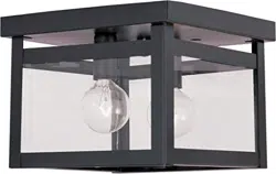
ASSEMBLING &
INSTALLATION INSTRUCTIONS PRODUCT# 5145 5146 5148 5149
WARNING! SHUT POWER OFF AT FUSE OR CIRCUIT BREAKER .
Fig.1
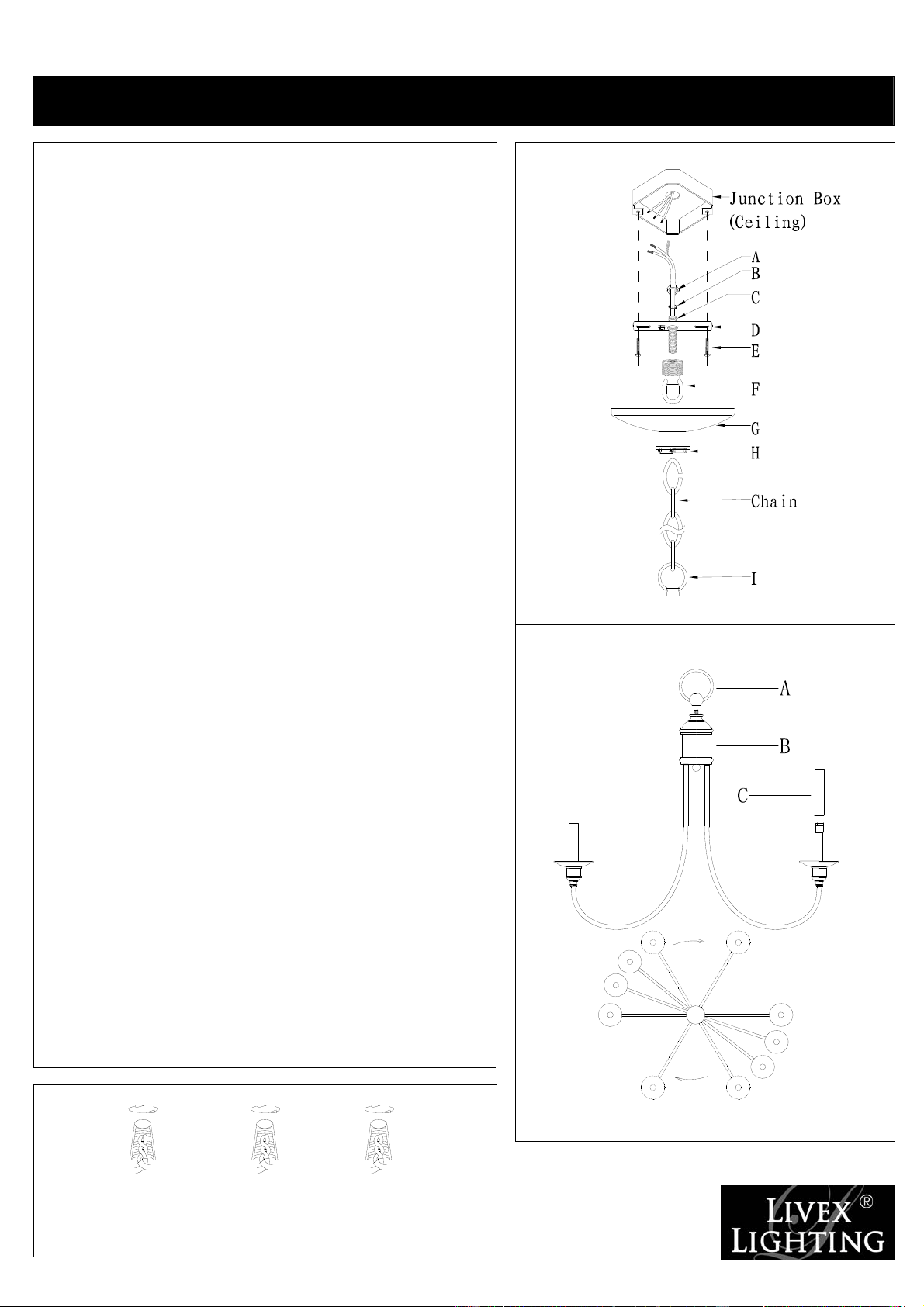
ASSEMBLING THE FIXTURE (Fig.2).
1. Return the arms to suitable position, see figure.2.
2. Attach the loop (A) to the top of fixture body’s nipple, by turning it
clockwise until tight.
3. Place the socket sleeve (C) over the socket holder.
4. Install the light bulbs in accordance with the fixture specifications
NOTE: DO NOT EXCEED THE SPECIFIED WATTAGE!
HANGING THE FIXTURE (Fig.1)
1. Shut off the power at the circuit breaker and remove old fixture
from ceiling, including the old single bar.
2. Carefully unpack new fixture and lay all the parts on a clear
surface.
3. Thread nipple (C) into loop (F) until snug.
4. Thread other end of nipple (C) with loop attached into single bar
(D) until snug.
5. Place lock washer (B) over end of nipple protruding through single
bar and thread hex nut (A) onto nipple until tight.
6. Take this single bar assembly and mount to ceiling junction box
with junction box screws (E). Tighten screws securely with
screwdriver.
7. Using proper chain pliers to open one end link of the chain
provided and connect to the fixture loop (I). Close the link.
8. By measuring, determine correct number of links needed for
proper hanging height. Using proper chain pliers disconnect and
discard remaining chain.
9. Lace the fixture wires through the chain.
10. Slip loop collar (H) over the chain, then do the same with the
canopy (G).
11. Open the other end link of the chain and hang the fixture on the
loop at the ceiling. Close the link.
12. Feed the fixture wires through the loop (F) and nipple (C) and pull
until taut.
13. Slide canopy (G) up flush to ceiling, secure using loop (H).
CONNECTING THE WIRES (Fig.3)
1. Take the black wire from the ceiling junction box and the smooth
wire leg from the fixture and twist bare ends together. Twist wire
connector onto end of wire until snug.
2. Repeat same process with white junction box wire and ribbed wire
leg of fixture wire. NOTE: Twist wires together in the same
direction you twist the wire connector onto wires.
3. If your junction box has a grounding wire (green or bare copper),
attach this wire and the bare copper wire from the fixture together
as step 1.If junction box has no ground wire, attach the bare copper
fixture wire to the green ground screw on the single bar.
4. Tuck these wire connections neatly into the ceiling outlet box and
then raise the canopy (G) all the way to the ceiling. Raise the loop
(H) and thread onto ceiling loop protruding through canopy
Your installation is now complete. Return power to the
junction box and test the fixture.
Fig.2
Fig.3
White or
HOUSE
Black
WIRES
(Hot)
Smooth
FIXTURE
WIRES
Black or
Ribbed
WIRES
FIXTURE
Bare Copper(Ground)
FIXTURE
WIRES
Copper
(Ground)
HOUSE
(Neutral)
WIRES
White
Bare
Green or
WIRES
HOUSE