Loading ...
Loading ...
Loading ...
en Installation and connection
6
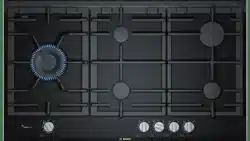
Clearances
A range hood fitted above the top must be installed
according to the installation instructions for the range
hood. A minimum distance of 650 mm is required for a
range hood and 750 mm for an exhaust fan.
Any adjoining wall surface situated within 200 mm from
the edge of any hob burner must be a suitable non-
combustible material for a height of 150 mm for the
entire length of the hob. Any combustible construction
above the hotplate must be at least 650 mm above the
top of the burner and no construction shall be within
450 mm above the top of the burner.
Height of the pan support above the bench top surface:
up to 60 mm.
A minimum depth of 50 mm from the top of the worktop
surface must be provided for the appliance.
If the base of the hotplate can be touched, a protecting
shield must be fitted.
■ The shield must be at least 10 mm from the lowest
part of the hotplate and must be capable of
withstanding the appliance temperatures. Minimum
thickness of benchtop is 30 mm.
■ The shield material must be mdf or similar with
minimum thickness of 12 mm.
■ The shield overall dimensions must be 560 mm wide
x 480 mm deep.
■ Provide cut-out in right hand rear of shield of 80 mm
wide x 80 mm deep to provide for gas regulator / LP
connection fitting.
After installation of the shield the clearance around the
top and sides of shield will allow adequate ventilation.
Ensure the side and top clearances are not obstructed.
If an oven is positioned below the cooktop the barrier
does not need to be fitted, but a space of 35 mm must
be maintained between the underside of the cooktop
and the top of the oven.
Installation of cooktop into the kitchen
bench
Side clearances: If the distance measured from the
periphery of the nearest burner to any vertical surface is
less than 200 mm, the surface shall be protected in
accordance with clauses 6.10.1.2 of AS/NZS 5601.1.
Make an appropriate size cut in the work surface.
Seal all work surfaces made of wood with special
sealer/glue to protect it against moisture damage.
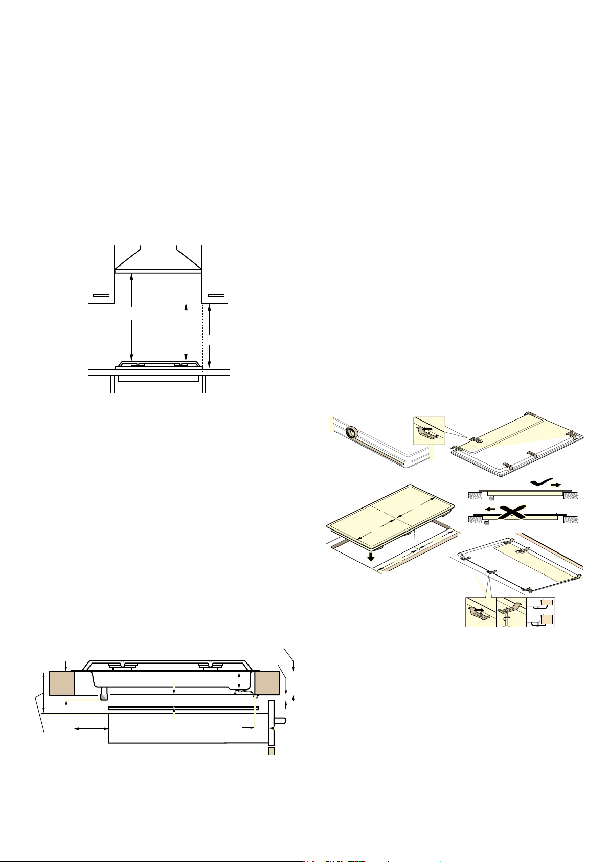
Note: Wear protective gloves to fit the hob.
The clips and adhesive seal (underside of the hob) are
factory-fitted: Do not remove these under any
circumstances: The adhesive seal prevents water
seepage.
Securing the appliance to the fitted unit:
1. Turn the hob into the correct position.
2. Loosen the screws on the brackets so they can turn
freely. You do not need to fully undo the screws on
the brackets.
3. Insert the appliance evenly into the cut-out.
4. Turn the brackets and tightly screw them in. The
screws for the brackets must be vertical to the base
of the housing.
The position of the brackets depends on the worktop
thickness.
Do not stick the hob onto the worktop with silicone.
Electrical connection
An electrical 10 amp socket needs to be within 1 m of
the hotplate to allow electrical connection. The socket
must remain accessible after installation of the
appliance.
Important notes:
■ This appliance is connected to the mains (240 VAC)
by means of the connecting lead which must be
fixed to the kitchen unit to prevent it from coming
into contact with hot parts of the cooktop (or an oven
installed underneath) and remain accessible after
installation of the cooktop.
PLQ
PLQ
PLQ
PLQ
PLQ
PLQ
P
L
Q
PD[
PLQ
[
[
Loading ...
Loading ...
Loading ...