
10/23/2023 15 & 24 INCH INSTALL GUIDETEC_TM_156 | REV. G | EN
PRESERVE THE MOMENT
®
15 INCH AND 24 INCH UNDERCOUNTER
INSTALL GUIDE AND USER'S MANUAL
“C” REVISION
TRUE RESIDENTIAL
®
838155-G

TRUE RESIDENTIAL
®
TEC_TM_156 | REV. G | EN10/23/2023Page 2 of 100
THANK YOU
FOR YOUR PURCHASE
CONTENTS
INSTALLATION CHECKLIST 4
SAFETY INFORMATION & OWNERSHIP
OWNERSHIP 6
REFRIGERANT SAFETY & WARNING INFORMATION
6
BASIC SAFETY & WARNING PRECAUTIONS 7
PROPER DISPOSAL OF THE APPLIANCE 7
NOTICE TO CUSTOMER 8
REGISTER YOUR PRODUCT 8
CONTACT INFORMATION 8
OUTDOOR USE 9
PRIOR TO INSTALLATION
ANTI-SWEAT FOAM END PANELS 12
ROUGH OPENING—SOLID & GLASS DOOR 13
ROUGH OPENING—STACKED UNITS 14
PLAN VIEWS 15
CUSTOM PANEL SPECIFICATIONS 25
DOOR OVERLAY PANEL INSTALLATION 30
DRAWER OVERLAY PANEL INSTALLATION 32
WINE RACK HANDLE & OVERLAY PANEL
FINISH APPLICATION 34
STACKING KIT INSTALLATION 37
ELECTRICAL INSTALLATION & SAFETY 40
INSTALLATION
UNCRATING 44
ANTI-TIP BRACKET INSTALLATION 45
LEVELING 46
120° DOORSTOP INSTALLATION 47
KICKPLATE INSTALLATION 47
90° HINGE INSTALLATION (OPTIONAL) 48
APPLIANCE SETUP
GLASS SHELF ADJUSTMENT 52
WINE RACK ADJUSTMENT 52
DRAFT STANDARD INSTALL & HOOK UP 54
DRAFT STANDARD INSTALL (COUNTERTOP) 58

TEC_TM_156 | REV. G | EN 10/23/2023 Page 3 of 10015 & 24 INCH INSTALL GUIDE
CONTENTS
DRIP TRAY INSTALLATION 59
DISPENSING PRESSURE 60
TAPPING 60
DRAFT BEER PROBLEMS 60
CHANGING CO
2
GAS CYLINDER 61
CO
2
REGULATOR PRESSURE ADJUSTMENT 61
DRAFT TOWER CLEANING 62
APPLIANCE OPERATION
TRUE PRECISION CONTROL
®
OPERATION &
APPLIANCE COMPONENTS (ALL MODELS) 64
24 INCH REFRIGERATOR & FREEZER 66
24 INCH DUAL ZONE 72
24 INCH REFRIGERATOR / FREEZER
DRAWERS 74
15 INCH REFRIGERATOR 77
HOME ALARM SYSTEM
(DUAL ZONE WINE CABINET ONLY) 81
GENERAL MAINTENANCE, CARE
& CLEANING
CONDENSER COIL CLEANING 84
CONDENSATION 85
DRAWER REMOVAL, INSTALLATION & ADJUSTMENT
86
APPLIANCE CARE & CLEANING 89
SERVICING & ADJUSTMENTS
SERVICING & REPLACING COMPONENTS 92
HANDLE TIGHTENING 92
CONTACT INFORMATION 92
FREQUENTLY ASKED QUESTIONS 93
WARRANTY
WARRANTY 96

TRUE RESIDENTIAL
®
TEC_TM_156 | REV. G | EN10/23/2023Page 4 of 100
To ensure a proper installation, this checklist should be completed to ensure that no part of the process
has been overlooked.
☐ Have all packaging materials been removed?
☐ Have the anti-tip brackets been installed securely and are they properly engaging the unit?
☐ Is the unit leveled properly with all leveling legs making contact with the floor? Has the toe
kick been installed?
☐ Has door stop been installed (if needed)?
☐ Are panels attached securely and properly aligned? (Overlay appliances only).
☐ Does the customer understand the unit’s operation?
☐ Has the customer been given the key and literature package?
☐ Have stainless steel surfaces been inspected for any imperfections? This is to be done by
the authorized True dealer or installer with the customer, upon completion of installation.
Stainless steel doors, handles and shelves are covered by a limited 30-day warranty for
cosmetic defects.
☐ Is the unit operating properly? If not, is the unit plugged in? Is the control turned on?
INSTALLATION CHECKLIST

TEC_TM_156 | REV. G | EN 10/23/2023 Page 5 of 10015 & 24 INCH INSTALL GUIDE
OWNERSHIP
REFRIGERANT SAFETY & WARNING INFORMATION
BASIC SAFETY & WARNING PRECAUTIONS
PROPER DISPOSAL OF THE CABINET
NOTICE TO CUSTOMER
REGISTER YOUR PRODUCT
CONTACT INFORMATION
OUTDOOR USE
SAFETY INFORMATION & OWNERSHIP
PRESERVE THE MOMENT
®
TRUE RESIDENTIAL
®
TEC_TM_156 | REV. G | EN10/23/2023Page 6 of 100
SAFETY INFORMATION & OWNERSHIP
OWNERSHIP
To ensure that your unit works properly from the
first day, it must be installed properly. We highly
recommend a trained refrigeration mechanic and
electrician install your True equipment. The cost of a
professional installation is money well spent.
Before you start to install your TRUE unit, carefully
inspect it for freight damage. IF DAMAGE IS DISCOVERED,
DO NOT INSTALL THE UNIT OR PUT IT IN SERVICE. Notify
True customer service, and immediately file a claim
with the delivery freight carrier.
TRUE is not responsible for damage incurred during
shipment.
For any questions about installation, please contact
your True dealer or True Residential Technical Service
at 844-746-9423 or TrueResidentialService@TrueMfg.com.
Please have your model and serial number available.
WARNING – Use this appliance for its
intended purpose as described in this
Installation Manual.
REFRIGERANT SAFETY & WARNING
INFORMATION
See the serial label inside the appliance for the units
refrigeration type. For Hydrocarbon Refrigeration
(R-600A only), see below:
DANGER – Risk of fire or explosion.
Flammable refrigerant used. DO NOT
use mechanical devices to defrost
refrigerator. DO NOT puncture refrigerant
tubing; follow handling instructions
carefully. To be repaired only by trained
service personnel.
DANGER – Risk of fire or explosion
(flammable refrigerant used), consult
repair manual/owner’s guide before
attempting to service this product. All
safety precautions must be followed.
Dispose of properly in accordance with
local and federal regulations. Follow all
safety precautions.
CAUTION – Keep all ventilation openings
clear of obstruction in the appliance
enclosure or in the structure housing the
appliance.
TEC_TM_156 | REV. G | EN 10/23/2023 Page 7 of 10015 & 24 INCH INSTALL GUIDE
SAFETY INFORMATION & OWNERSHIP
• Take care during operation, maintenance or repairs
to avoid cuts or pinching from any part/component
of the appliance.
• Units may pose a tipping hazard while uncrating,
during installation, or when moving the unit.
• Ensure the unit is properly installed and located in
accordance with the Installation Instructions before
use.
• This appliance is not to be used, cleaned or
maintained by persons (including children) with
reduced physical, sensory or mental capabilities or
lack of experience and knowledge, unless they have
been given supervision or instruction.
• DO NOT allow children to play with the appliance
or climb, stand, or hang on the unit’s shelves to
prevent damage to the refrigerator and personal
injury.
• DO NOT touch the cold surfaces in the freezer
compartment when hands are damp or wet. Skin
may stick to these extremely cold surfaces.
• Unplug the refrigerator before cleaning and making
repairs.
• Setting temperature controls to the 0 position or
powering off an electronic control may not remove
power from all components (e.g., light circuits,
perimeter heaters, and evaporator fans).
• DO NOT store or use gasoline, or other flammable
vapors and liquids, in the vicinity of this or any
other appliance.
• DO NOT store explosive substances such as aerosol
cans with a flammable propellant in this appliance.
• Keep fingers out of the “pinch point” areas;
clearances between the doors and appliance are
necessarily small; be careful closing doors when
children are in the area.
• DO NOT use electrical appliances inside the food
storage compartments of the units unless the
appliances are of the type recommended by the
manufacturer.
BASIC SAFETY & WARNING PRECAUTIONS
PROPER DISPOSAL OF THE APPLIANCE
DANGER! RISK OF CHILD
ENTRAPMENT
Child entrapment and suffocation are not problems of
the past. Junked or abandoned refrigerators are still
dangerous, even if they will sit for “just a few days.” If
you are getting rid of your old refrigerator, please follow
the instructions below to help prevent accidents.
Before throwing away your old refrigerator or freezer:
• Take off the doors.
• Leave the shelves in place so that children may not
easily climb inside.
DANGER – Risk of fire or explosion.
Flammable insulation and/or refrigerant
used. Dispose of all in accordance with
local and federal regulations. Follow all
safety precautions.
TRUE RESIDENTIAL
®
TEC_TM_156 | REV. G | EN10/23/2023Page 8 of 100
SAFETY INFORMATION & OWNERSHIP
NOTICE TO CUSTOMER
Loss or spoilage of products in your refrigerator/freezer
is not covered by warranty. In addition to following
recommended installation
procedures, run the refrigerator/
freezer for 24 hours prior
to usage to verify its proper
operation.
REGISTER YOUR PRODUCT
To qualify for TRUE’s extended 7–12 year parts
only sealed system warranty, you must register your
product* within 12 months of the unit’s installation
date. To register your unit, complete and submit the
form at www.true-residential.com/product-registration.
For warranty details, please see page 96.
* Please note that ice machines do not qualify for this
extended warranty.
CONTACT INFORMATION
For any questions about installation, please contact your TRUE dealer or TRUE Residential Technical Service.
Please have your model and serial number (see serial label location below) available so we can better assist you
with your service- or parts-related inquiries.
Customer Service
Phone: 888-616-8783
info@true-residential.com
Technical Service Department
Phone: 844-746-9423
TrueResidentialService@truemfg.com
Warranty Department
Phone: 844-849-6179
TrueResidentialWarranty@truemfg.com
SERIAL LABEL LOCATION
Your serial label contains important information such as your model name and serial number. The label is located
on the upper left interior wall.

TEC_TM_156 | REV. G | EN 10/23/2023 Page 9 of 10015 & 24 INCH INSTALL GUIDE
SAFETY INFORMATION & OWNERSHIP
OUTDOOR USE
All True undercounter units are rated for outdoor use.
• In regions with high dew points or humidity,
condensation may appear on the glass and around
gasket seals. For best operation, keep the unit fully
stocked with product.
• In areas where the ambient temperature regularly
exceeds 95°F (35°C), vent the rear of the rough
opening for optimum performance. Recommended
vent size is 4” x 10” (102 mm x 254 mm).
• For the best operation, install your True unit with
your outdoor bar/kitchen countertop covering the
door or drawer gasket (flush install). The rough
opening should be at least 24” (606.6 mm) deep.
NOTE: DOOR AND DRAWER GASKETS DO NOT
PROVIDE A WATERTIGHT SEAL AGAINST THE
ELEMENTS.
WINTERIZING
When the temperature consistently reaches 32°F (0°C)
or below, winterize your unit.
1. Remove all product from the unit.
2. Unplug the unit or turn the unit off.
3. Place a cover over the unit.

TRUE RESIDENTIAL
®
TEC_TM_156 | REV. G | EN10/23/2023Page 10 of 100
NOTES

TEC_TM_156 | REV. G | EN 10/23/2023 Page 11 of 10015 & 24 INCH INSTALL GUIDE
PRIOR TO INSTALLATION
ANTI-SWEAT FOAM END PANELS
ROUGH OPENING—SOLID & GLASS DOOR
ROUGH OPENING—STACKED UNITS
PLAN VIEWS
CUSTOM PANEL SPECIFICATIONS
WINE RACK HANDLE & OVERLAY PANEL FINISH APPLICATION
DOOR OVERLAY PANEL INSTALLATION
DRAWER OVERLAY PANEL INSTALLATION
STACKING KIT INSTALLATION
ELECTRICAL INSTALLATION & SAFETY
PRESERVE THE MOMENT
®
TRUE RESIDENTIAL
®
TEC_TM_156 | REV. G | EN10/23/2023Page 12 of 100
ANTI-SWEAT FOAM END PANELS
When installing two or more True units side-by-
side, TRUE recommends installing one (1) foam
pad between the appliances (on either appliance) to
prevent moisture from developing.
To order foam pads, contact our parts department at
844-849-6226 or TrueResidentialParts@TrueMfg.com.
PRIOR TO INSTALLATION
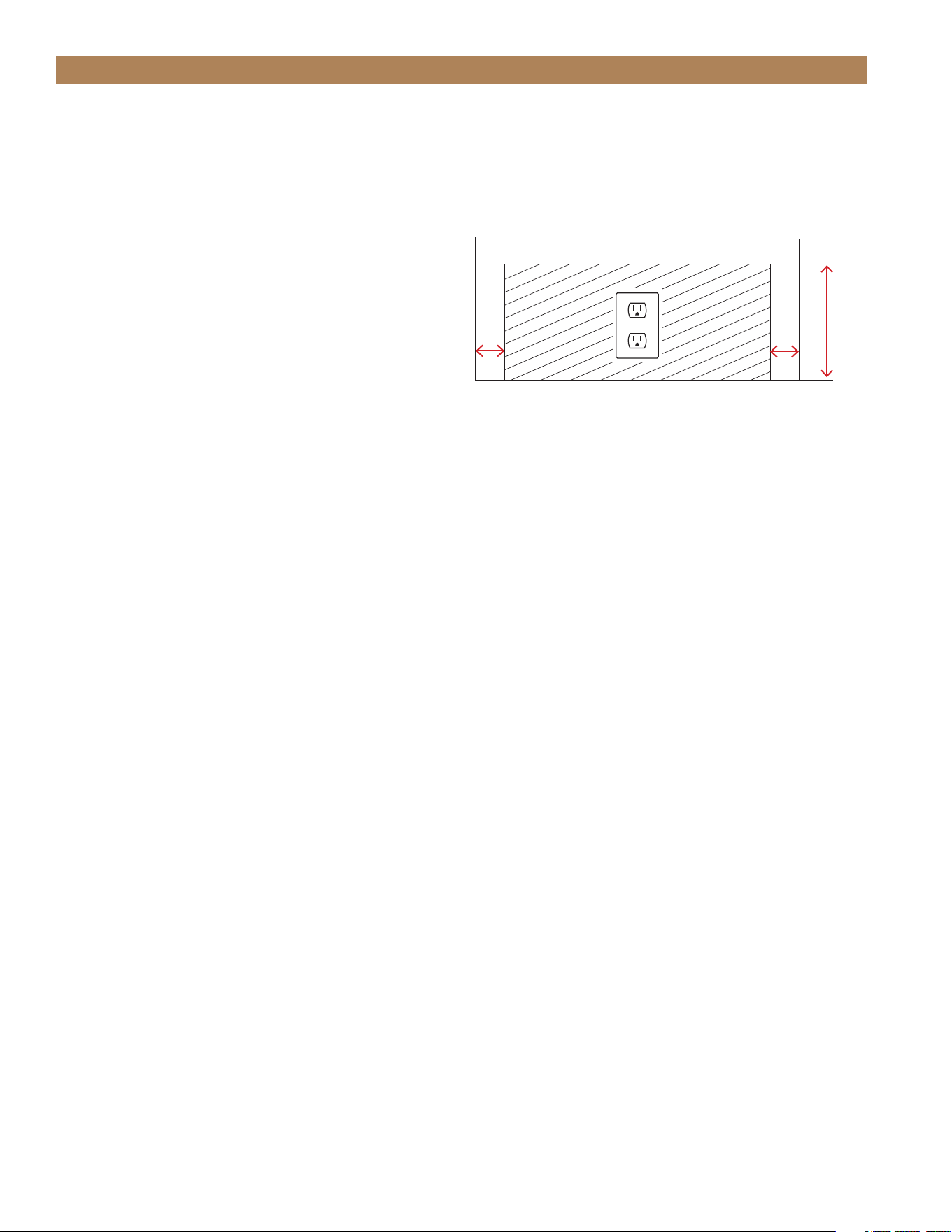
2"
(51 mm)
2"
(51 mm)
Rear wall of cut out
8"
(203 mm)
CUTOUT OPENINGS
To minimize the depth of the cutout opening, the
electrical outlet must be positioned as shown below.
Outlet must be flush with the wall.
TEC_TM_156 | REV. G | EN 10/23/2023 Page 13 of 10015 & 24 INCH INSTALL GUIDE
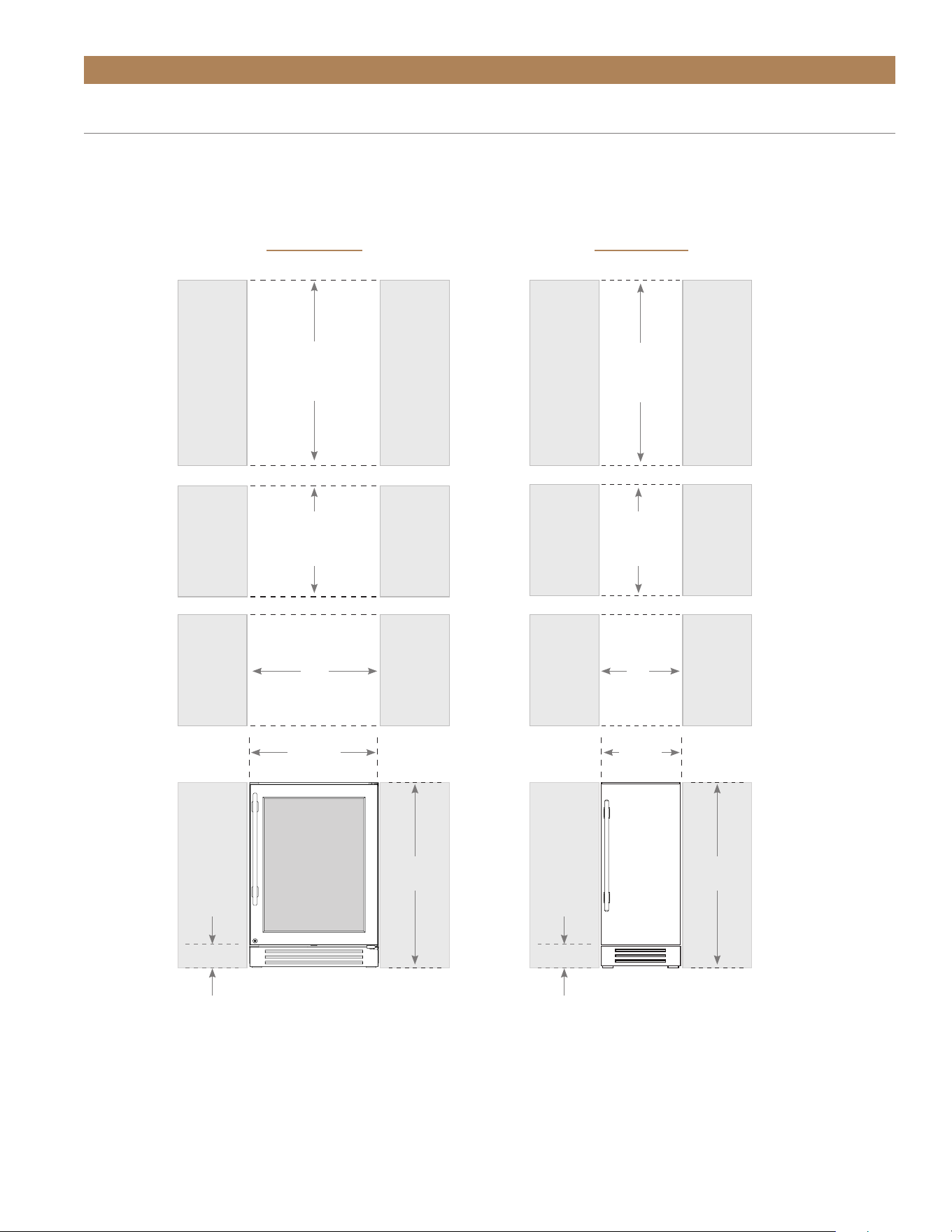
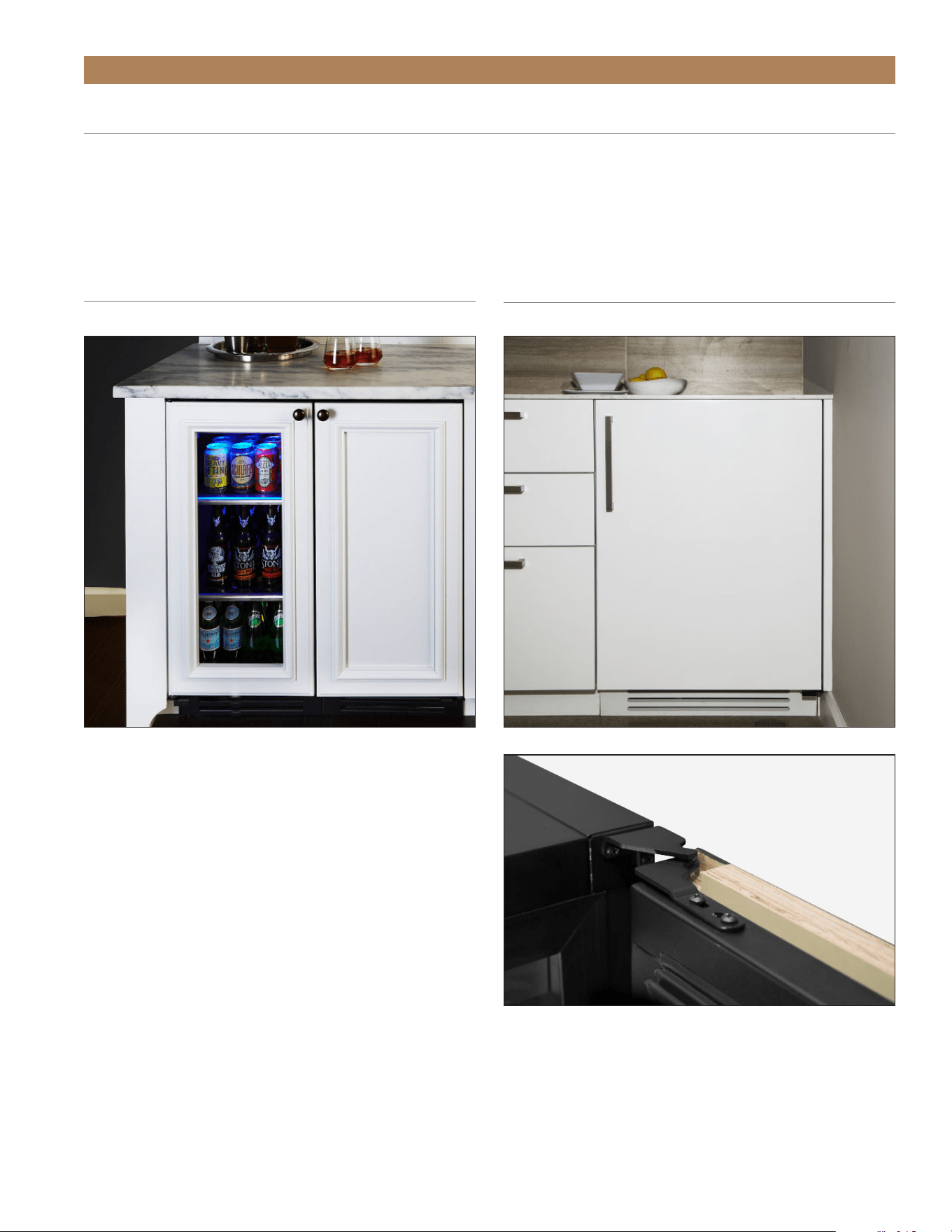
ROUGH OPENING – SOLID & GLASS DOOR
True’s Stainless Solid and Glass Door units are designed to be inserted into a cabinet opening or free standing.
Below are recommended dimensions for rough opening.
PRIOR TO INSTALLATION
DEPTH
24"
(610 mm)
HEIGHT
34-1/2"
(877 mm)
WIDTH
15"
(381 mm)
14-7/8"
(378 mm)
34-1/2"
(877 mm)
4-1/8"
(105 mm)
Front view
of unit
between
cabinets
15 INCH
HEIGHT
34-1/2"
(877 mm)
DEPTH
24"
(610 mm)
WIDTH
24"
(610 mm)
23-7/8"
(606 mm)
34-1/2"
(877 mm)
4-1/8"
(105 mm)
"
Front view
of unit
between
cabinets
24 INCH

TRUE RESIDENTIAL
®
TEC_TM_156 | REV. G | EN10/23/2023Page 14 of 100
HEIGHT
69-1/2"
(1766 mm)
DEPTH
24"
(610 mm)
WIDTH
24"
(610 mm)
PRIOR TO INSTALLATION
ROUGH OPENING – STACKED UNITS
(SOLID, GLASS DOOR, AND OVERLAY PANELS)
True’s stacked units are designed to be inserted into a cabinet opening or free standing. Below are recommended
dimensions for rough opening.
HEIGHT
69-1/2"
(1766 mm)
WIDTH
15"
(381 mm)
DEPTH
24"
(610 mm)
15 INCH24 INCH
TEC_TM_156 | REV. G | EN 10/23/2023 Page 15 of 10015 & 24 INCH INSTALL GUIDE
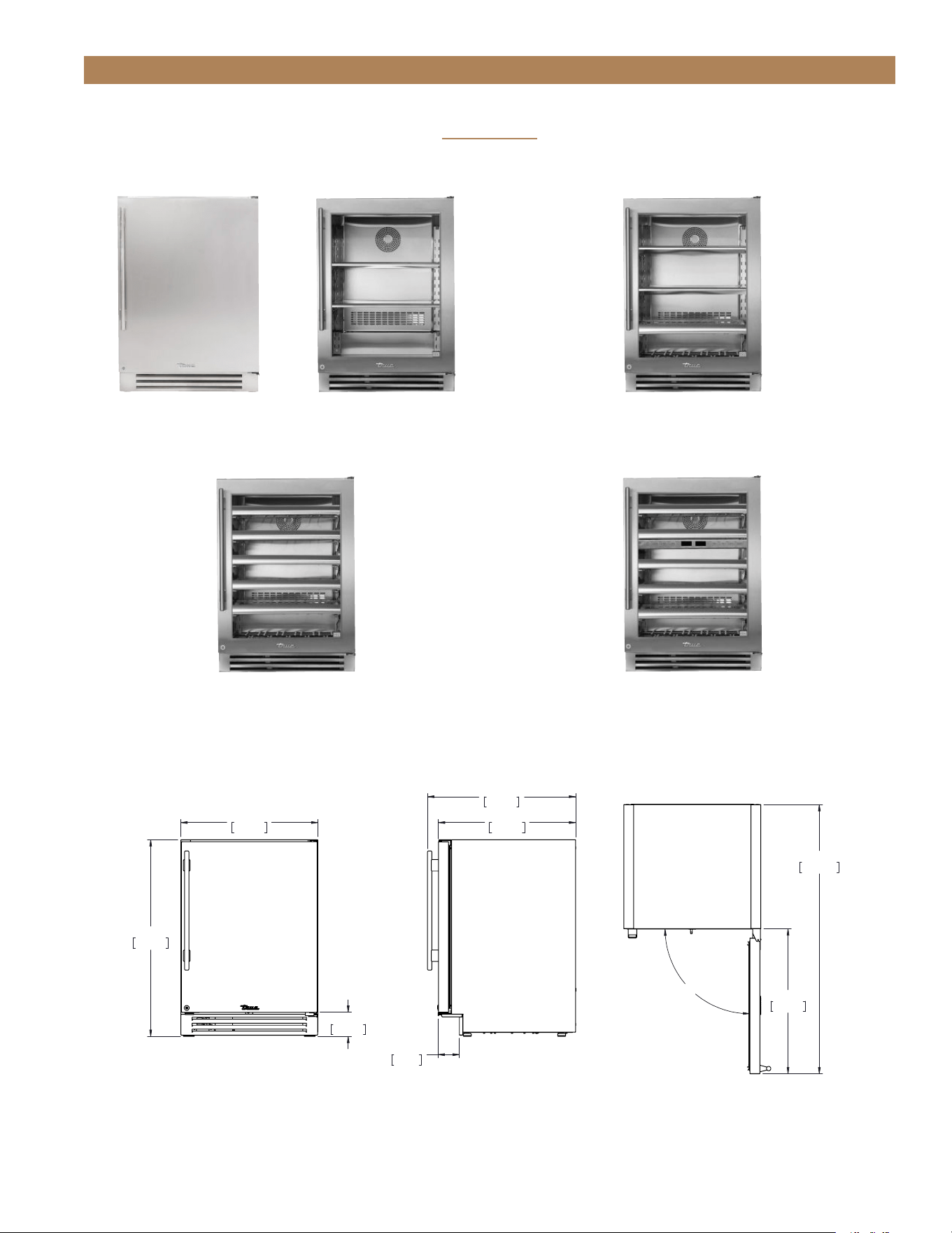
23 7/8"
606mm
34 1/4"
870mm
4 3/16"
107mm
25 13/16"
655mm
23 29/32"
607mm
3 23/32"
95mm
90°
25 1/4"
641mm
46 7/8"
1191mm
TUR-24-R-SS-B
PRIOR TO INSTALLATION
24 INCH
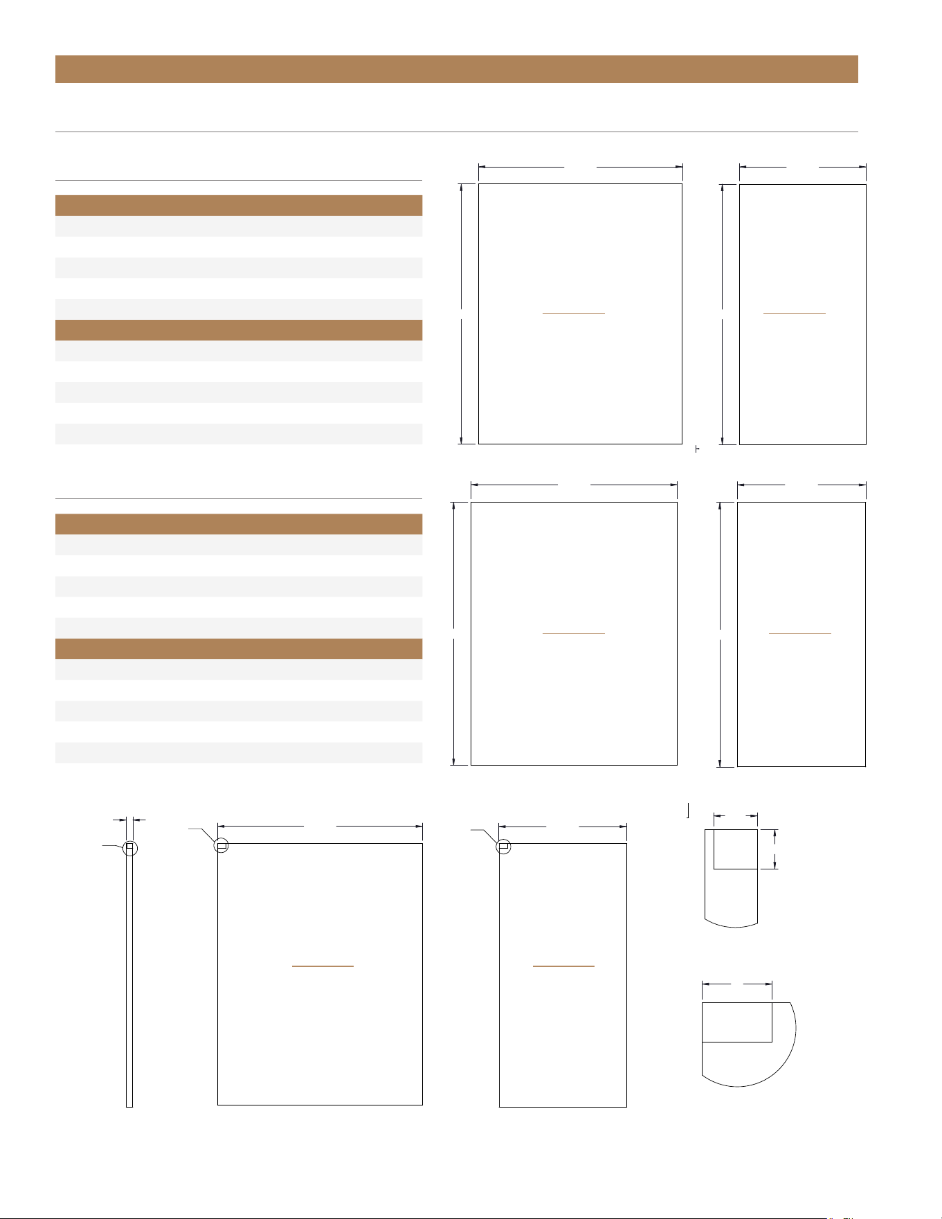
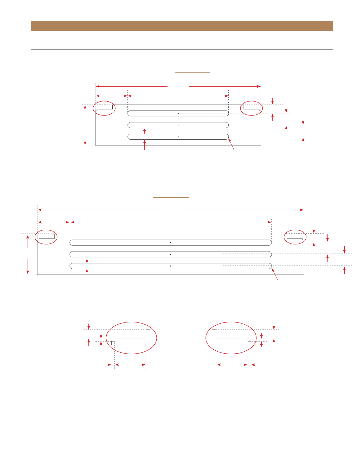
PLAN VIEW DIMENSIONS
FRONT SIDE TOP
TUF-24-R/L-SS-C TUR-24-R/L-SG-C
REFRIGERATOR / FREEZER
TBC-24-R/L-SG-C
BEVERAGE CENTER
Dimensions may vary by ± 1/8" (3.2 mm)
TWC-24-R/L-SG-C
WINE CABINET
TWC-24DZ-R/L-SG-C
DUAL ZONE WINE CABINET
TRUE RESIDENTIAL
®
TEC_TM_156 | REV. G | EN10/23/2023Page 16 of 100
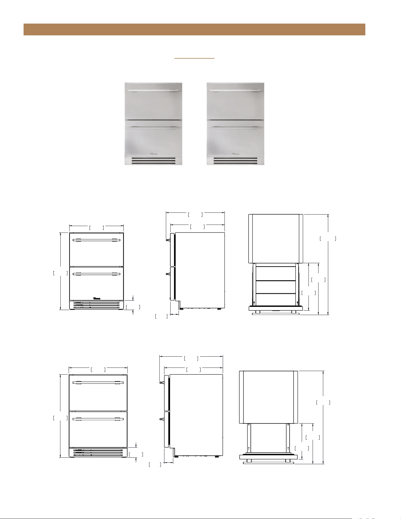
34 1/4"
870mm
23 7/8"
606mm
4 3/16"
106mm
3 5/8"
92mm
23 7/8"
606mm
25 25/32"
655mm
44 17/32"
1131mm
21"
533mm
22 29/32"
582mm
TUR-24-D-SS-B
PRIOR TO INSTALLATION
24 INCH
FREEZER PLAN VIEW DIMENSIONS
REFRIGERATOR PLAN VIEW DIMENSIONS
FRONT
FRONT
SIDE
SIDE
TOP
TOP
Dimensions may vary by ± 1/8" (3.2 mm)
REFRIGERATOR
TUR-24-D-SS-C
FREEZER
TUF-24-D-SS-C
34 1/4"
870mm
23 7/8"
606mm
4 3/16"
106mm
3 5/8"
92mm
23 7/8"
606mm
25 25/32"
655mm
38 9/32"
972mm
14 3/4"
375mm
16 21/32"
423mm
TUF-24-D-SS-B
TEC_TM_156 | REV. G | EN 10/23/2023 Page 17 of 10015 & 24 INCH INSTALL GUIDE
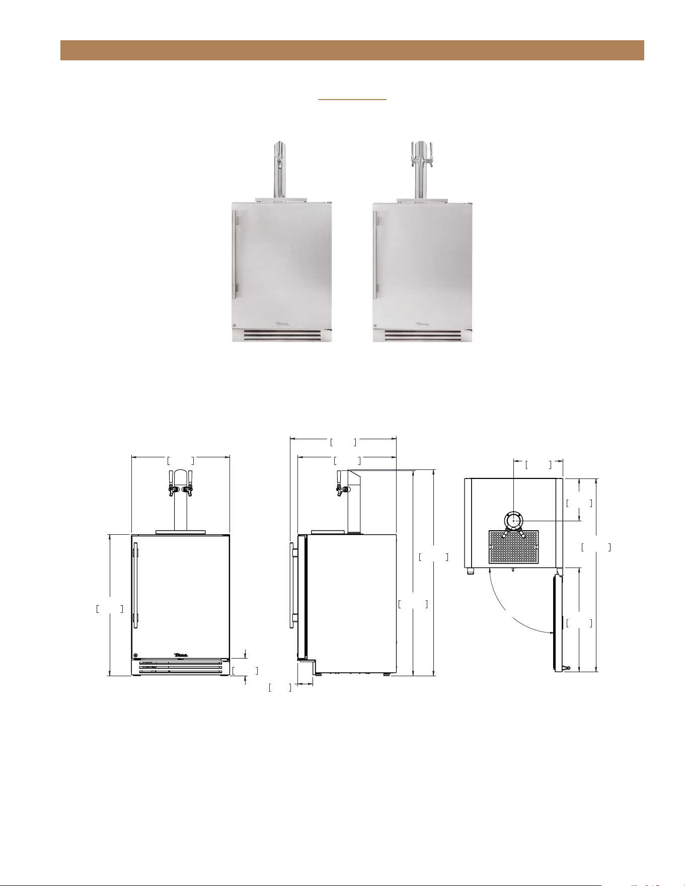
PRIOR TO INSTALLATION
TUR-24BD-R/L-SS-C TUR-24DD-R/L-SS-C
24" SINGLE TAP UNIT ACCOMMODATES (1) SHORT 1/4
BARREL, (1) SLIM 1/4 BARREL, OR (1) 1/6 BARREL.
24" DUAL TAP UNIT ACCOMMODATES (2) 1/6 BARRELS
OR (1) SLIM 1/4 BARREL AND (1) 1/6 BARREL.
34 1/4"
870mm
23 7/8"
606mm
4 3/16"
107mm
23 29/32"
607mm
25 13/16"
655mm
49 11/16"
1262mm
49 31/32"
1269mm
3 23/32"
95mm
90°
25 1/4"
641mm
46 7/8"
1191mm
11 15/16"
303mm
10 9/32"
261mm
TUR-24DD-R-SS-B
24 INCH
BEVERAGE CENTER
PLAN VIEW DIMENSIONS
FRONT
SIDE
TOP
Dimensions may vary by ± 1/8" (3.2 mm)
TRUE RESIDENTIAL
®
TEC_TM_156 | REV. G | EN10/23/2023Page 18 of 100
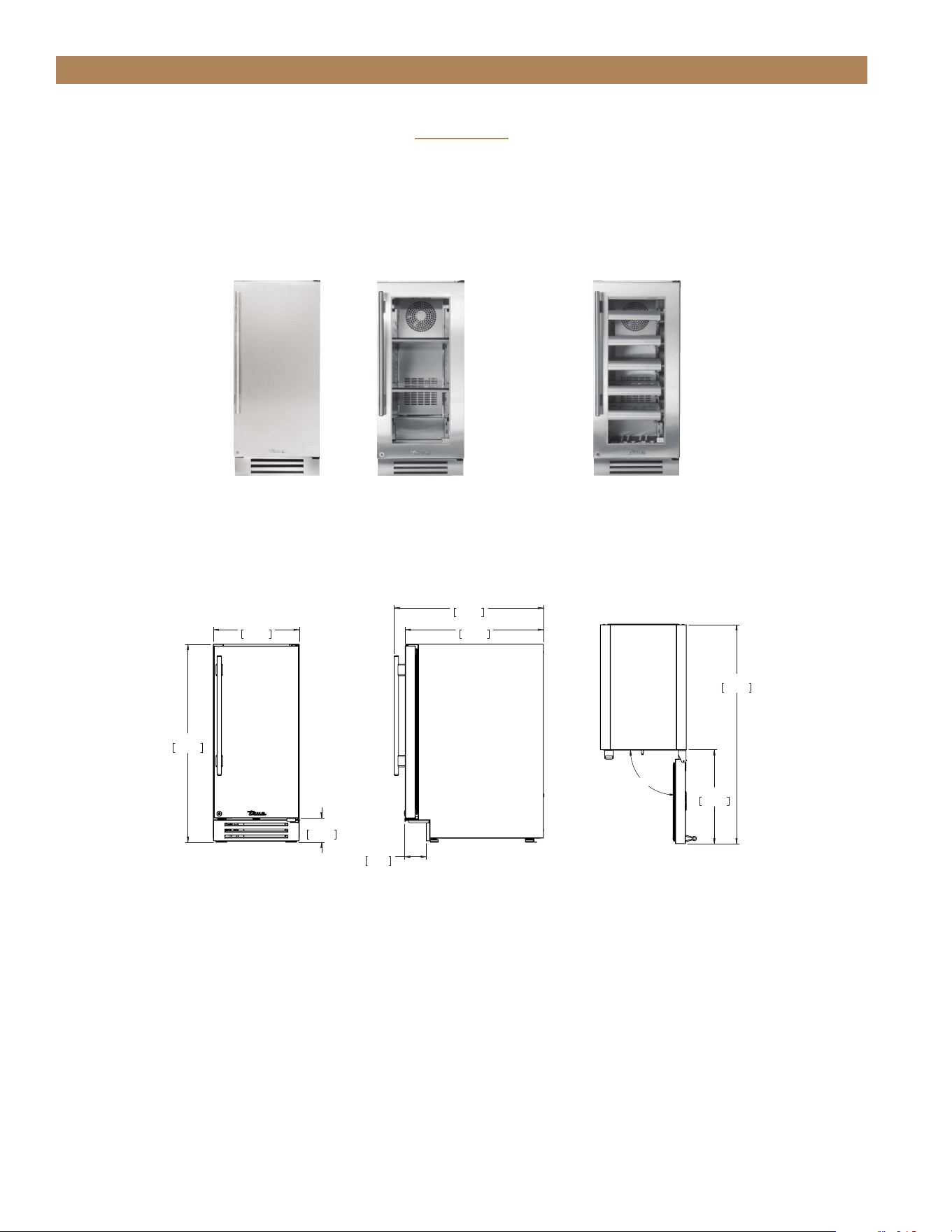
34 1/4"
870mm
14 7/8"
378mm
4 3/16"
107mm
25 13/16"
655mm
23 29/32"
607mm
3 23/32"
95mm
90°
16 1/4"
413mm
37 7/8"
962mm
TUR-15-R-SS-B
PRIOR TO INSTALLATION
15 INCH
PLAN VIEW DIMENSIONS
FRONT
SIDE
TOP
Dimensions may vary by ± 1/8" (3.2 mm)
TUR-15-R/L-SS-C TUR-15-R/L-SG-C
ALL REFRIGERATORS
TWC-15-R/L-SG-C
WINE CABINET
TEC_TM_156 | REV. G | EN 10/23/2023 Page 19 of 10015 & 24 INCH INSTALL GUIDE
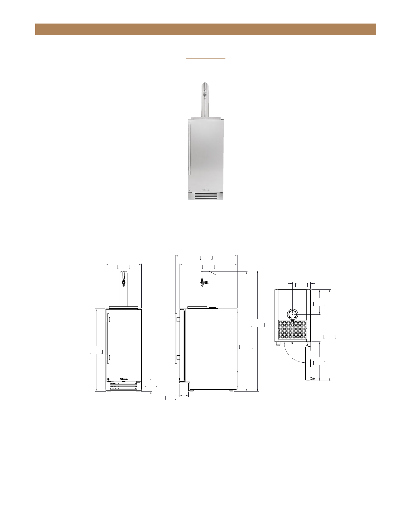
PRIOR TO INSTALLATION
15 INCH
15" SINGLE TAP UNIT ACCOMMODATES (1) SLIM 1/4 BARREL
OR (1) 1/6 BARREL.
TUR-15BD-R/L-SS-C
BEVERAGE DISPENSER
PLAN VIEW DIMENSIONS
Dimensions may vary by ± 1/8" (3.2 mm)
FRONT SIDE TOP
4 3/16"
106mm
34 1/4"
870mm
14 7/8"
378mm
49 11/16"
1262mm
25 13/16"
655mm
23 29/32"
607mm
49 31/32"
1269mm
3 23/32"
95mm
90°
37 7/8"
962mm
10 9/32"
261mm
7 7/16"
189mm
16 1/4"
413mm
TUR-15BD-R-SS-B
TRUE RESIDENTIAL
®
TEC_TM_156 | REV. G | EN10/23/2023Page 20 of 100
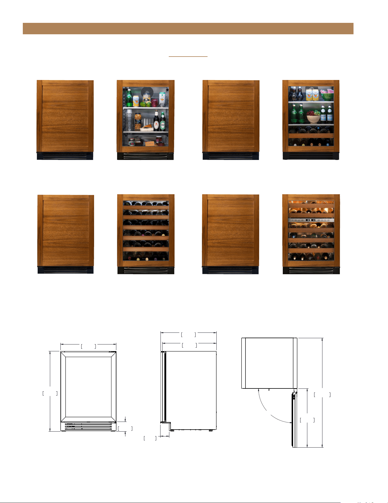
34 1/4"
870mm
23 7/8"
606mm
4 3/32"
104mm
23 5/32"
588mm
3 23/32"
95mm
23 15/16"
608mm
90°
25 1/4"
641mm
46 7/8"
1191mm
TUR-24-R-OP-B
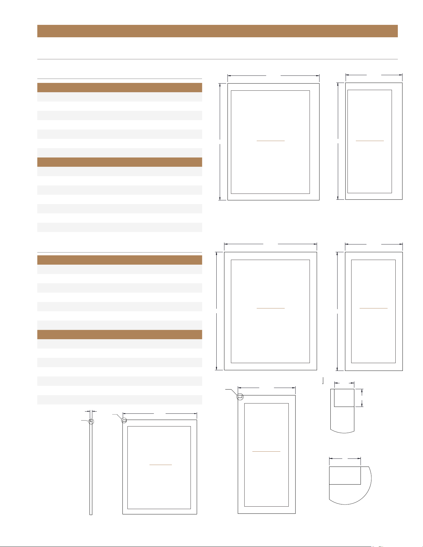
PRIOR TO INSTALLATION
24 INCH
PLAN VIEW DIMENSIONS*
FRONT
SIDE
TOP
WINE CABINET
REFRIGERATOR / FREEZER
TUR-24-R/L-OG-CTUR-24-R/L-OP-C
BEVERAGE CENTER
TBC-24-R/L-OP-C TBC-24-R/L-OG-C
TWC-24-R/L-OP-C TWC-24-R/L-OG-C
DUAL ZONE WINE CABINET
TWC-24DZ-R/L-OG-CTWC-24DZ-R/L-OP-C
NOTE: Unit shown with overlay panel (not provided by True)
*Depth measurement includes 3/4" thick panel (not provided by TRUE).
Dimensions may vary by ± 1/8" (3.2 mm)
TEC_TM_156 | REV. G | EN 10/23/2023 Page 21 of 10015 & 24 INCH INSTALL GUIDE
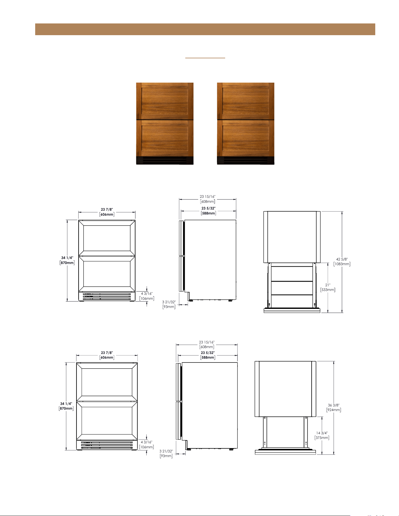
PRIOR TO INSTALLATION
24 INCH
34 1/4"
870mm
23 7/8"
606mm
4 3/16"
106mm
3 21/32"
93mm
23 5/32"
588mm
23 15/16"
608mm
36 3/8"
924mm
14 3/4"
375mm
TUF-24-D-OP-B
34 1/4"
870mm
23 7/8"
606mm
4 3/16"
106mm
3 21/32"
93mm
23 5/32"
588mm
23 15/16"
608mm
21"
533mm
42 5/8"
1083mm
TUR-24-D-OP-B
FRONT
FRONT
SIDE
SIDE
TOP
TOP
NOTE: Unit shown with overlay panel (not provided by True)
REFRIGERATOR / FREEZER DRAWERS
TUR-24-D-OP-C TUF-24-D-OP-C
*Depth measurement includes 3/4" thick panel (not provided by TRUE).
Dimensions may vary by ± 1/8" (3.2 mm)
FREEZER PLAN VIEW DIMENSIONS*
REFRIGERATOR PLAN VIEW DIMENSIONS*
TRUE RESIDENTIAL
®
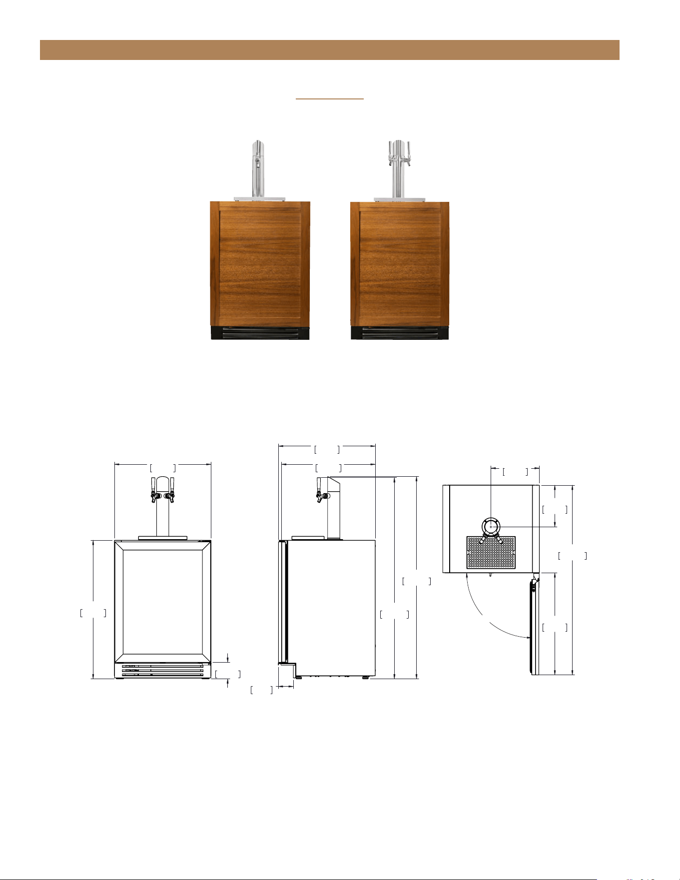
TEC_TM_156 | REV. G | EN10/23/2023Page 22 of 100
34 1/4"
870mm
23 7/8"
606mm
4 3/32"
104mm
3 23/32"
95mm
23 5/32"
588mm
49 11/16"
1262mm
23 15/16"
608mm
49 31/32"
1269mm
90°
25 1/4"
641mm
46 7/8"
1191mm
11 15/16"
303mm
10 9/32"
261mm
TUR-24DD-R-OP-B
PRIOR TO INSTALLATION
24 INCH
BEVERAGE DISPENSER
FRONT SIDE TOP
NOTE: Unit shown with overlay panel (not provided by True)
24" SINGLE TAP UNIT ACCOMMODATES (1) SHORT 1/4 BARREL, (1) SLIM
1/4 BARREL, OR (1) 1/6 BARREL. 24" DUAL TAP UNIT ACCOMMODATES (2) 1/6
BARRELS OR (1) SLIM 1/4 BARREL AND (1) 1/6 BARREL.
TUR-24BD-R/L-OP-C TUR-24DD-R/L-OP-C
*Depth measurement includes 3/4" thick panel (not provided by TRUE).
Dimensions may vary by ± 1/8" (3.2 mm)
PLAN VIEW DIMENSIONS*
TEC_TM_156 | REV. G | EN 10/23/2023 Page 23 of 10015 & 24 INCH INSTALL GUIDE
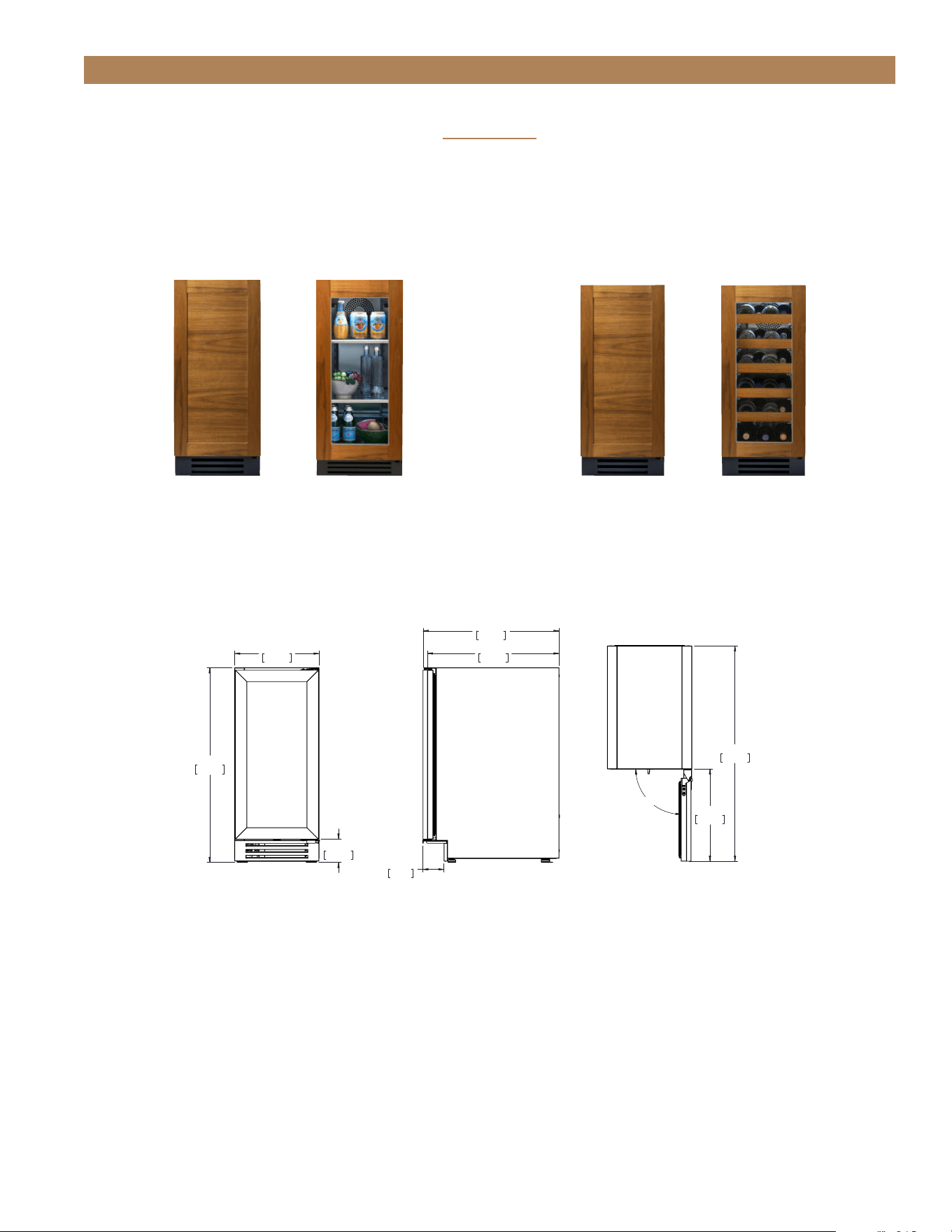
34 1/4"
870mm
14 7/8"
378mm
4 3/32"
104mm
23 15/16"
608mm
23 5/32"
588mm
3 23/32"
95mm
16 1/4"
413mm
37 7/8"
962mm
90°
TUR-15-R-OP-C
TUR-15-R/L-OP-C TUR-15-R/L-OG-C TWC-15-R/L-OP-C TWC-15-R/L-OG-C
PRIOR TO INSTALLATION
15 INCH
ALL REFRIGERATOR WINE CABINET
FRONT SIDE TOP
NOTE: Unit shown with overlay panel (not provided by True)
*Depth measurement includes 3/4" thick panel (not provided by TRUE).
Dimensions may vary by ± 1/8" (3.2 mm)
PLAN VIEW DIMENSIONS*
TRUE RESIDENTIAL
®
TEC_TM_156 | REV. G | EN10/23/2023Page 24 of 100
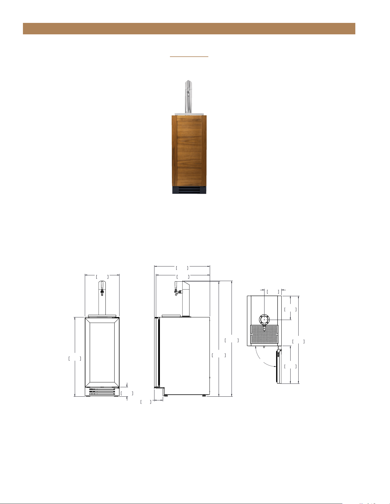
34 1/4"
870mm
14 7/8"
378mm
4 3/32"
104mm
23 15/16"
608mm
23 5/32"
588mm
3 23/32"
95mm
49 11/16"
1262mm
49 31/32"
1269mm
90°
37 7/8"
962mm
7 7/16"
189mm
10 9/32"
261mm
16 1/4"
413mm
TUR-15BD-R-OP-B
TUR-15BD-R/L-OP-C
PRIOR TO INSTALLATION
15 INCH
BEVERAGE DISPENSER
FRONT SIDE TOP
NOTE: Unit shown with overlay panel (not provided by True)
15" SINGLE TAP UNIT ACCOMMODATES (1) SLIM
1/4 BARREL OR (1) 1/6 BARREL.
*Depth measurement includes 3/4" thick panel (not provided by TRUE).
Dimensions may vary by ± 1/8" (3.2 mm)
PLAN VIEW DIMENSIONS*
TEC_TM_156 | REV. G | EN 10/23/2023 Page 25 of 10015 & 24 INCH INSTALL GUIDE
PRIOR TO INSTALLATION
CUSTOM PANEL SPECIFICATIONS
Overlay units can be fitted with custom panels to match adjacent cabinetry. Two specification options for panels
sizes are given in these instructions for overlay units: Standard overlays and Integrated Panels. The standard
overlay panel dimensions fully cover the provided appliance door. The integrated panel options extend above the
door and conceal the hinge assembly to match full overlay cabinet doors. See pictures below for reference.
STANDARD OVERLAY PANEL
INTEGRATED OVERLAY PANEL
TRUE RESIDENTIAL
®
TEC_TM_156 | REV. G | EN10/23/2023Page 26 of 100
29 32/32"
14 5/8"
29 23/32"
23 5/8"
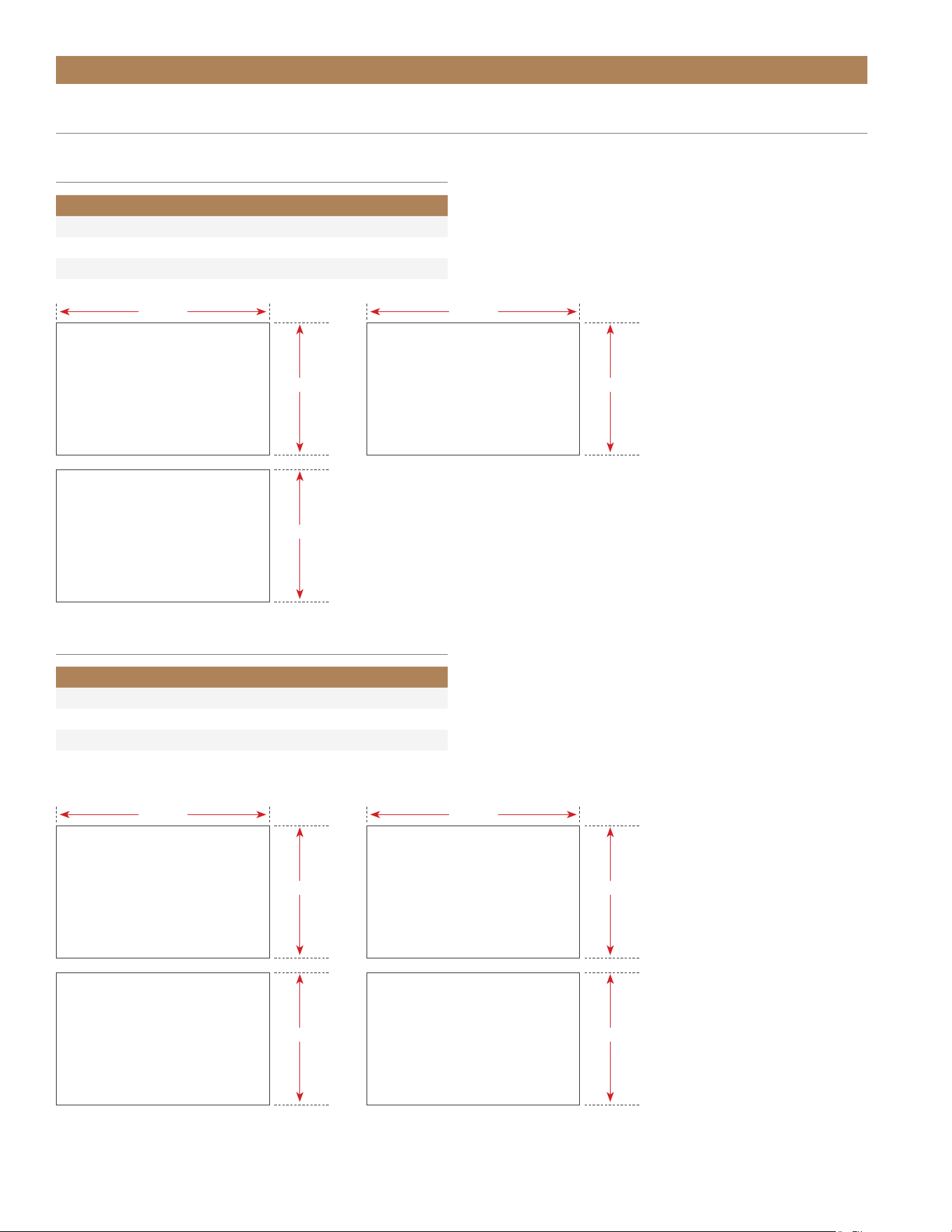
PRIOR TO INSTALLATION
STANDARD OVERLAY PANEL
INTEGRATED OVERLAY PANEL
CUSTOM PANEL SPECIFICATIONS – SOLID DOOR REFRIGERATOR / FREEZER
30 1/8"
14 5/8"
30 1/8"
23 5/8"
24 INCH
FRONT
24 INCH
FRONT
15 INCH
FRONT
15 INCH
FRONT
3/4"
A
B
14 5/8"
5/8"
9/16"
DETAIL A
SCALE 1 : 1
1"
DETAIL B
SCALE 1 : 1
B
23 5/8"
15 INCH24 INCH
BACKBACK
24" IN / LB MM / KG
Width 23-5/8 600
Height 29-23/32 754.9
Depth 3/4 (max) 19 (max)
Weight 10 lb (max) 4.5 kg (max)
Rail Style Dimension 2 (min) 50.8 (min)
15" IN / LB MM / KG
Width 14-5/8 371.5
Height 29-23/32 754.9
Depth 3/4 (max) 19 (max)
Weight 10 lb (max) 4.5 kg (max)
Rail Style Dimension 2 (min) 50.8 (min)
24" IN / LB MM / KG
Width 23-5/8 600
Height 30-1/8 765.2
Depth 3/4 (max) 19 (max)
Weight 10 lb (max) 4.5 kg (max)
Rail Style Dimension 2 (min) 50.8 (min)
15" IN / LB MM / KG
Width 14-5/8 371.5
Height 30-1/8 765.2
Depth 3/4 (max) 19 (max)
Weight 10 lb (max) 4.5 kg (max)
Rail Style Dimension 2 (min) 50.8 (min)
TEC_TM_156 | REV. G | EN 10/23/2023 Page 27 of 10015 & 24 INCH INSTALL GUIDE
PRIOR TO INSTALLATION
CUSTOM PANEL SPECIFICATIONS – GLASS DOOR REFRIGERATOR
29 32/32"
14 5/8"
29 23/32"
23 5/8"
24 INCH
FRONT
15 INCH
FRONT
STANDARD OVERLAY PANEL
30 1/8"
14 5/8"
30 1/8"
23 5/8"
24 INCH
FRONT
15 INCH
FRONT
INTEGRATED OVERLAY PANEL
3/4"
A
B
23 5/8"
24 INCH
B
14 5/8"
5/8"
9/16"
DETAIL A
SCALE 1 : 1
1"
DETAIL B
SCALE 1 : 1
15 INCH
24" IN / LB MM / KG
Width 23-5/8 600
Height 29-23/32 754.9
Depth 3/4 (max) 19 (max)
Weight 10 lb. (max) 4.5 kg (max)
Rail Style Dimension 2 (min) 50.8 (min)
Viewable Area Width 19-5/8 498.5
Viewable Area Height 25-23/32 653.3
15" IN / LB MM / KG
Width 14-5/8 371.5
Height 29-23/32 765.2
Depth 3/4 (max) 19 (max)
Weight 10 lb. (max) 9.1 kg (max)
Rail Style Dimension 2 (min) 50.8 (min)
Viewable Area Width 10-5/8 269.9
Viewable Area Height 25-23/32 653.3
24" IN / LB MM / KG
Width 23-5/8 600
Height 30 -1/8 765.2
Depth 3/4 (max) 19 (max)
Weight 10 lb. (max) 4.5 kg (max)
Rail Style Dimension 2 (min) 50.8 (min)
Viewable Area Width 19-5/8 498.5
Viewable Area Height 25-23/32 653.3
15" IN / LB MM / KG
Width 14-5/8 371.5
Height 30 -1/8 765.2
Depth 3/4 (max) 19 (max)
Weight 10 lb. (max) 4.5 kg (max)
Rail Style Dimension 2 (min) 50.8 (min)
Viewable Area Width 10-5/8 269.9
Viewable Area Height 25-23/32 653.3
BACK
BACK
TRUE RESIDENTIAL
®
TEC_TM_156 | REV. G | EN10/23/2023Page 28 of 100
PRIOR TO INSTALLATION
CUSTOM PANEL SPECIFICATIONS – DRAWER REFRIGERATOR / FREEZER
SPEC SAME PANEL FOR TOP & BOTTOM
FREEZER DRAWERS. FOR BOTTOM
DRAWER ROTATE PANEL 180º.
NOTE: TOP DRAWER WILL EXTEND ABOVE PROVIDED APPLIANCE FRONT
STANDARD OVERLAY PANEL
INTEGRATED OVERLAY PANEL
24" IN MM
Width 23-5/8 600
Height 14-11/16 373
Depth 3/4 (max) 19 (max)
24" IN MM
Width 23-5/8 600
Top Panel Height 15 -1/8 384
Bottom Panel Height 14-11/16 373
Depth 3/4 (max) 19 (max)
BOTTOM DRAWER
REFRIGERATOR
14-11/16"
BOTTOM DRAWER
REFRIGERATOR
14-11/16"
BOTTOM DRAWER
FREEZER
14-11/16"
TOP DRAWER
REFRIGERATOR
14-11/16"
23-5/8"
TOP DRAWER
REFRIGERATOR
15-1/8"
23-5/8"
TOP DRAWER
FREEZER
15-1/8"
23-5/8"
TOP & BOTTOM DRAWER
FREEZER
14-11/16"
23-5/8"
TEC_TM_156 | REV. G | EN 10/23/2023 Page 29 of 10015 & 24 INCH INSTALL GUIDE
PRIOR TO INSTALLATION
15 INCH
24 INCH
LOUVER TEMPLATE MEASURES
DETAIL A DETAIL B
14-3/4"
(375 mm)
25/32"
(20 mm)
1-1/32"
(26 mm)
9"
(229 mm)
2-7/8"
(73 mm)
3-5/8"
(92 mm)
1/2" (3 PLCS.)
(13 mm)
R1/4" (6 PLCS.)
(6.5 mm)
1-1/32"
(26 mm)
SCALE 2:3
Notch here for a
left hinged unit.
DETAIL A
13/32"
(10 mm)
1/8"
(3 mm)
5/32"
(4 mm)
1-3/8"
(35 mm)
1-3/8"
(35 mm)
DETAIL B
SCALE 2:3
Notch here for a
right hinged unit.
13/32"
(10 mm)
1/8"
(3 mm)
5/32"
(4 mm)
25/32"
(20 mm)
1-1/32"
(26 mm)
1-1/32"
(26 mm)
23-3/4"
(603 mm)
18"
(457 mm)
2-7/8"
(73 mm)
3-5/8"
(92 mm)
1/2" (3 PLCS.)
(13 mm)
R1/4" (6 PLCS.)
(6.5 mm)
DETAIL A DETAIL B
TRUE RESIDENTIAL
®
TEC_TM_156 | REV. G | EN10/23/2023Page 30 of 100
PRIOR TO INSTALLATION
DOOR OVERLAY PANEL INSTALLATION
Follow the instructions below to install door overlay
panels. Door overlay panel installation is the
same for solid and glass door units. For custom
panel specifications, please see “Custom Panel
Specifications” starting on page 25.
NOTE: DO NOT INSTALL A SOLID PANEL ON A
GLASS DOOR. THIS MAY CAUSE MOISTURE
TO FORM BEHIND THE PANEL, RESULTING IN
DAMAGE.
REQUIRED TOOLS
Required tools include (but may not be limited to)
the following:
• Surface Protection*
• 3/8" Wrench
• Phillips Bit Driver
• 2+ Clamps ≥ 2" (51 mm)
• 1/8" Drill Bit
• #6 Screws (qty 10)**
• Drill
*Cardboard, moving blanket, foam padding, etc.
** Screw type and length varies by material. All screws must
be 1/2" (13 mm) + Overlay Panel Thickness.
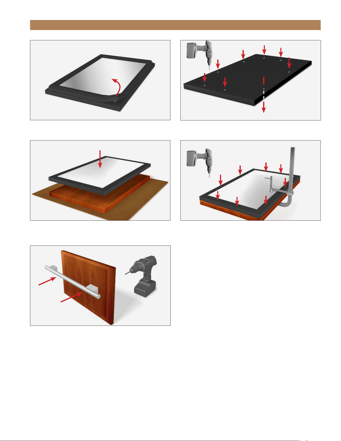
PROCEDURE
1. Carefully lay the door overlay panel on a protected
surface.
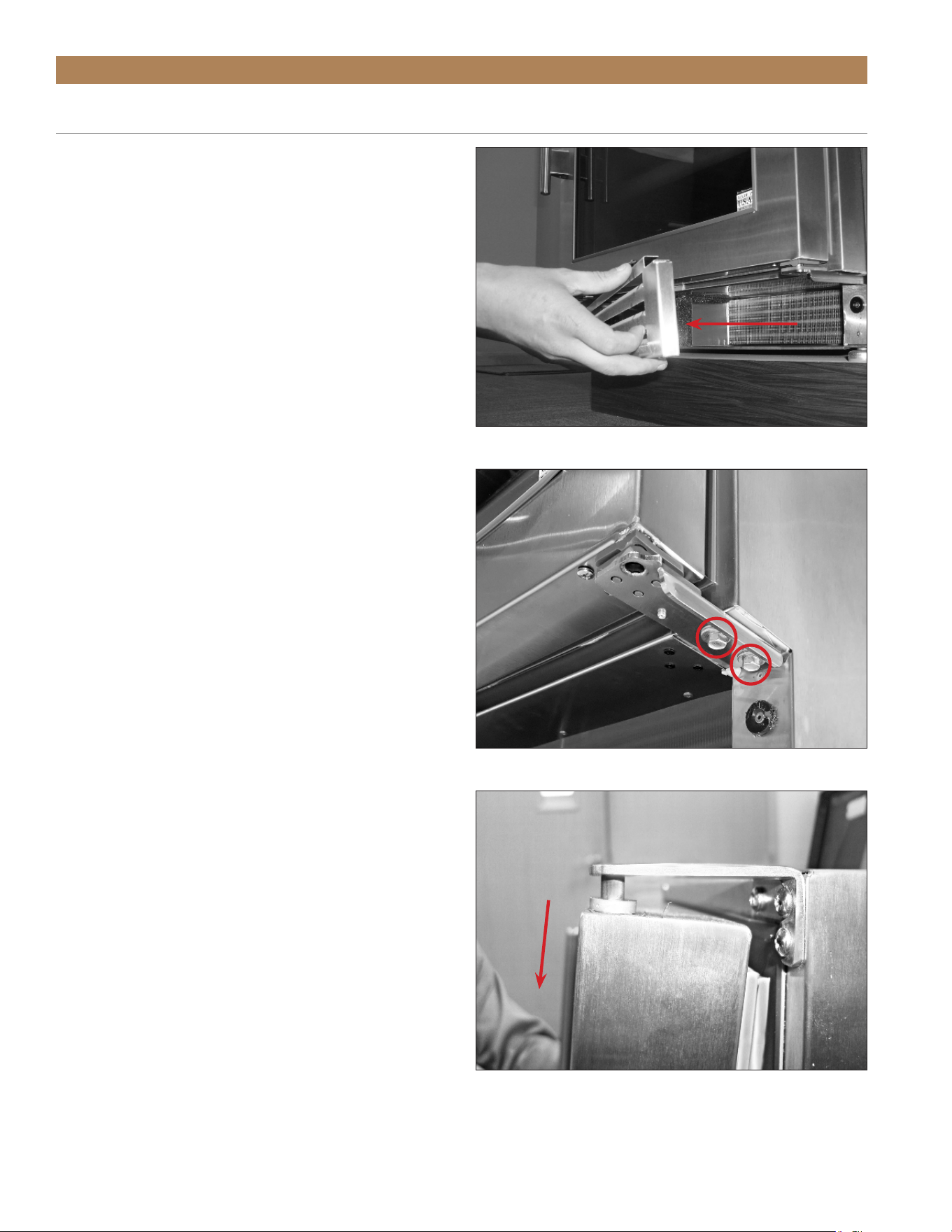
2. Remove the kickplate. See fig. 1.
3. Remove the door from the unit. Leave the hinges
installed on the unit. See fig. 2.
NOTE: BE SURE TO SUPPORT THE DOOR
WHILE REMOVING THE HINGE HARDWARE.
DO NOT DISCARD.
4. Remove the gasket. See fig. 3.
5. With a 1/8" drill bit, carefully drill the pre-marked
pilot holes in the door. See fig. 4.
6. Carefully place the door face down on the overlay
panel. Align the door and panel edges. See fig. 5.
7. Clamp the door and panel. See fig. 6
NOTE: IF THE CLAMP JAWS ARE NOT
PADDED, INSERT PADDING BETWEEN THE
CLAMP AND THE OVERLAY TO PROTECT THE
PANEL’S FINISH.
IF DESIRED, INSTALL A HANDLE BEFORE
PROCEEDING TO THE NEXT STEP. FOR BEST
INSTALLATION, FASTEN THE HANDLE WITH
RECESSED SCREWS. SEE FIGS. 7 AND 8.
8. Carefully drill pilot holes into the panel. See fig. 6.
NOTE: TAKE CARE TO NOT DRILL THROUGH
THE FRONT OF THE PANEL.
9. Fasten the overlay panel to the door front. Then,
remove the clamp(s).
10. Install the door gasket.
NOTE: VERIFY THE GASKET IS FULLY
SEATED IN THE GASKET CHANNEL.
11. Install the door assembly. Verify the door closes
correctly and the gasket seals without gaps.
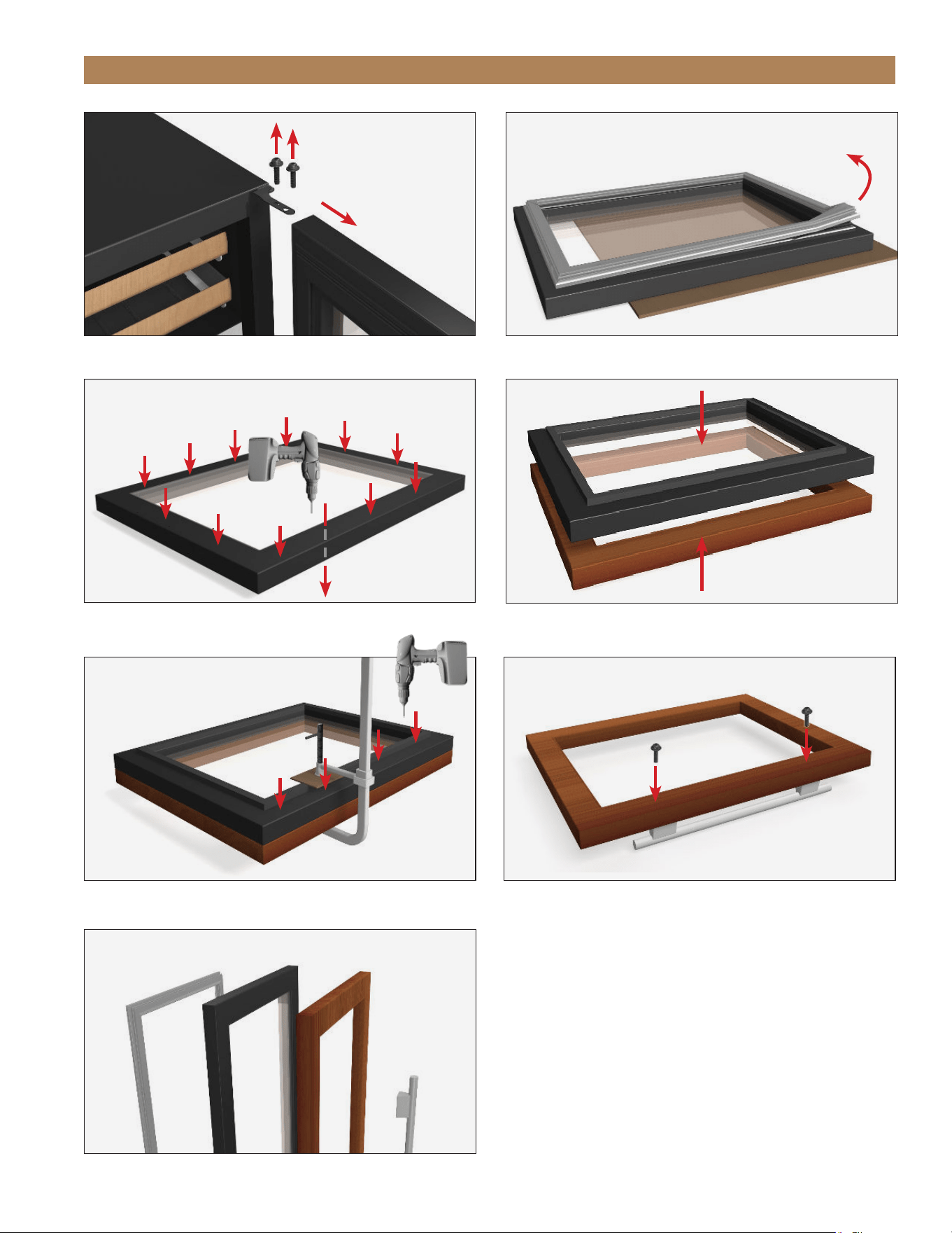
FIG. 1.
Pull the kickplate off the magnets.
TEC_TM_156 | REV. G | EN 10/23/2023 Page 31 of 10015 & 24 INCH INSTALL GUIDE
PRIOR TO INSTALLATION
FIG. 2.
Remove the hinge bolts from top and bottom hinge
FIG. 3.
Pull the gasket from the door.
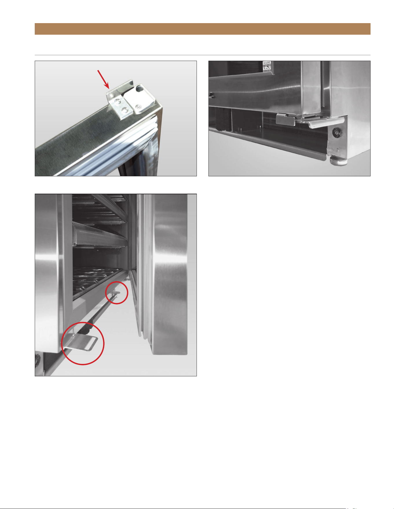
FIG. 4.
Drill pilot holes THROUGH the door assembly.
FIG. 5.
Be sure the edges are aligned before clamping the panel and
door assembly.
FIG. 6.
Be sure to NOT drill through the panel's front.
FIG. 7.
Install handles before fastening the overlay panel to the door.
FIG. 8.
Door assembly component order.
Gasket — Door — Overlay Panel — Handle
TRUE RESIDENTIAL
®
TEC_TM_156 | REV. G | EN10/23/2023Page 32 of 100
PRIOR TO INSTALLATION
DRAWER OVERLAY PANEL INSTALLATION
Follow the instructions below to install drawer overlay
panels. For custom panel specifications, please see
“Custom Panel Specifications” starting on page 25.
NOTE: REMOVE THE DRAWER FRONT AS
DESCRIBED FOR EASY OVERLAY PANEL
INSTALLATION.
REQUIRED TOOLS
Required tools include (but may not be limited to)
the following:
• Surface Protection*
• Phillips Bit Driver
• 1+ Clamp ≥ 2" (51 mm)
• 1/8" Drill Bit
• #6 Screws (qty 8)**
• Drill
*Cardboard, moving blanket, foam padding, etc.
**Screw type and length varies by material. All screws must be 1/2" (13
mm) + Overlay Panel Thickness.
PROCEDURE
1. Carefully lay the drawer overlay panel face down
on a protected surface.
2. With a Phillips bit driver, remove the drawer front
assembly. See fig. 1.
3. Remove the gasket. See fig. 2.
4. With a 1/8" drill bit, carefully drill the pre-marked
pilot holes in the drawer front. See fig. 3.
5. Place the drawer front face down on the overlay
panel. Align the drawer front and panel edges.
See fig. 4.
6. Clamp the drawer front and panel. See fig. 5.
NOTE: IF THE CLAMP JAWS ARE NOT
PADDED, INSERT PADDING BETWEEN THE
CLAMP AND THE OVERLAY TO PROTECT THE
PANEL’S FINISH.
IF DESIRED, INSTALL A HANDLE BEFORE
PROCEEDING TO THE NEXT STEP. FOR BEST
INSTALLATION, FASTEN THE HANDLE WITH
RECESSED SCREWS. SEE FIGS. 6.
7. Carefully drill pilot holes into the panel. See fig. 7.
NOTE: TAKE CARE TO NOT DRILL THROUGH
THE FRONT OF THE PANEL.
8. Fasten the overlay panel to the drawer front. Then,
remove the clamp(s).
9. Install the drawer gasket.
NOTE: VERIFY THE GASKET IS FULLY
SEATED IN THE GASKET CHANNEL.
10. Install the drawer front assembly. Verify the drawer
closes correctly and the gasket seals without gaps.
11. Repeat steps 1-10 for the second drawer.
FIG. 1.
Drawer front screw locations. Other side not shown.
TEC_TM_156 | REV. G | EN 10/23/2023 Page 33 of 10015 & 24 INCH INSTALL GUIDE
PRIOR TO INSTALLATION
FIG. 2.
Pull the gasket from the drawer front.
FIG. 3.
Drill pilot holes THROUGH the drawer front.
FIG. 4.
Be sure the edges are aligned before clamping the drawer front
assembly.
FIG. 5.
Be sure NOT to drill through the panel's front.
FIG. 6.
Install handles before fastening the overlay panel to the door.
Back of
drawer
Front of drawer
TRUE RESIDENTIAL
®
TEC_TM_156 | REV. G | EN10/23/2023Page 34 of 100
PRIOR TO INSTALLATION
See finish (e.g., paint or stain) for application
instructions and drying / curing times. Drying / Curing
times vary by finish.
NOTE: Finish odors from panels installed
before fully drying /curing can linger and
be absorbed by the appliance's interior.
True is not responsible for lingering finish
odors inside the unit.
WINE RACK HANDLES
Follow recommended guidelines associated with
treating unfinished natural cherry wood.
NOTE: Remove the wine rack handles from the wine
rack assembly before applying finish!
REQUIRED TOOLS
Required tools include (but may not be limited to) the
following:
• Phillips Screwdriver or Bit Driver
• Drill (optional)
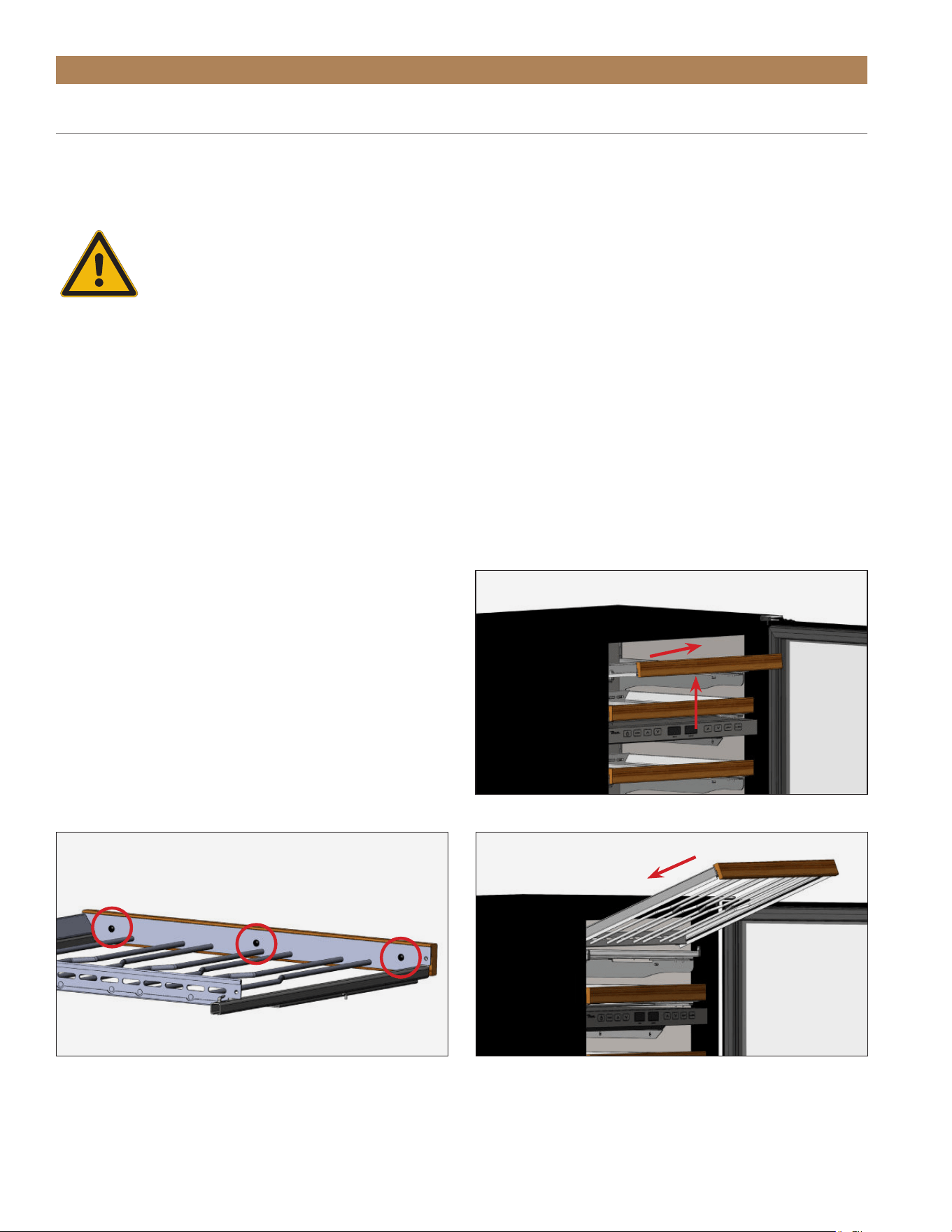
REMOVAL
1. Gently lift the wine rack handle and pull the wine
rack forward. See fig. 1.
2. Remove the wine rack handle from the wine rack
assembly. See fig. 2.
INSTALLATION
Finish odors from wine rack handles installed before
fully drying /curing can linger and be absorbed by the
appliance's interior. True is not responsible for lingering
finish odors inside the unit.
1. Install the wine rack handle on the wine rack
assembly. See fig. 2.
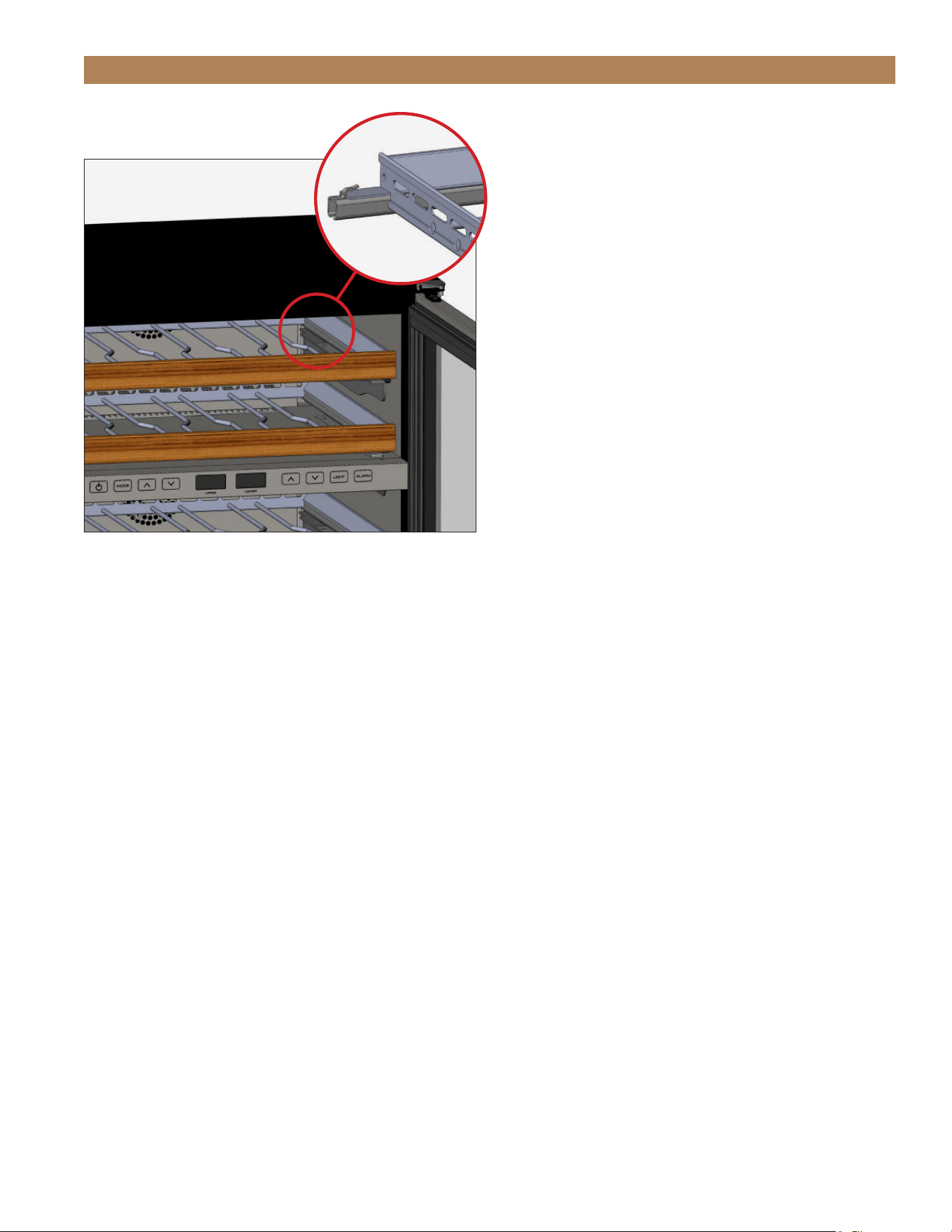
2. Position the wine rack on the slides and carefully
push the wine rack towards the back of the unit.
See fig. 3.
NOTE: BE SURE THE WINE RACK SITS
UNDER THE SLIDES REAR TABS. SEE FIG. 4.
WINE RACK HANDLE & OVERLAY PANEL FINISH APPLICATION
FIG. 1.
Lift and pull the wine rack forward.
FIG. 2.
Wine rack handle screw locations.
FIG. 3.
Slide the wine rack into place.
TEC_TM_156 | REV. G | EN 10/23/2023 Page 35 of 10015 & 24 INCH INSTALL GUIDE
PRIOR TO INSTALLATION
FIG. 4.
Be sure the wine rack sits under the rear tabs.
OVERLAY PANELS
See finish (e.g., paint or stain) for application
instructions and drying / curing times. Drying / Curing
times vary by finish.
For overlay panel installation and removal instructions,
please see “Solid (OP) And Glass Framed Panel (OG)
Installation” (page 30) or “Drawer Overlay Panel
Installation” (page 32).
TRUE RESIDENTIAL
®
TEC_TM_156 | REV. G | EN10/23/2023Page 36 of 100
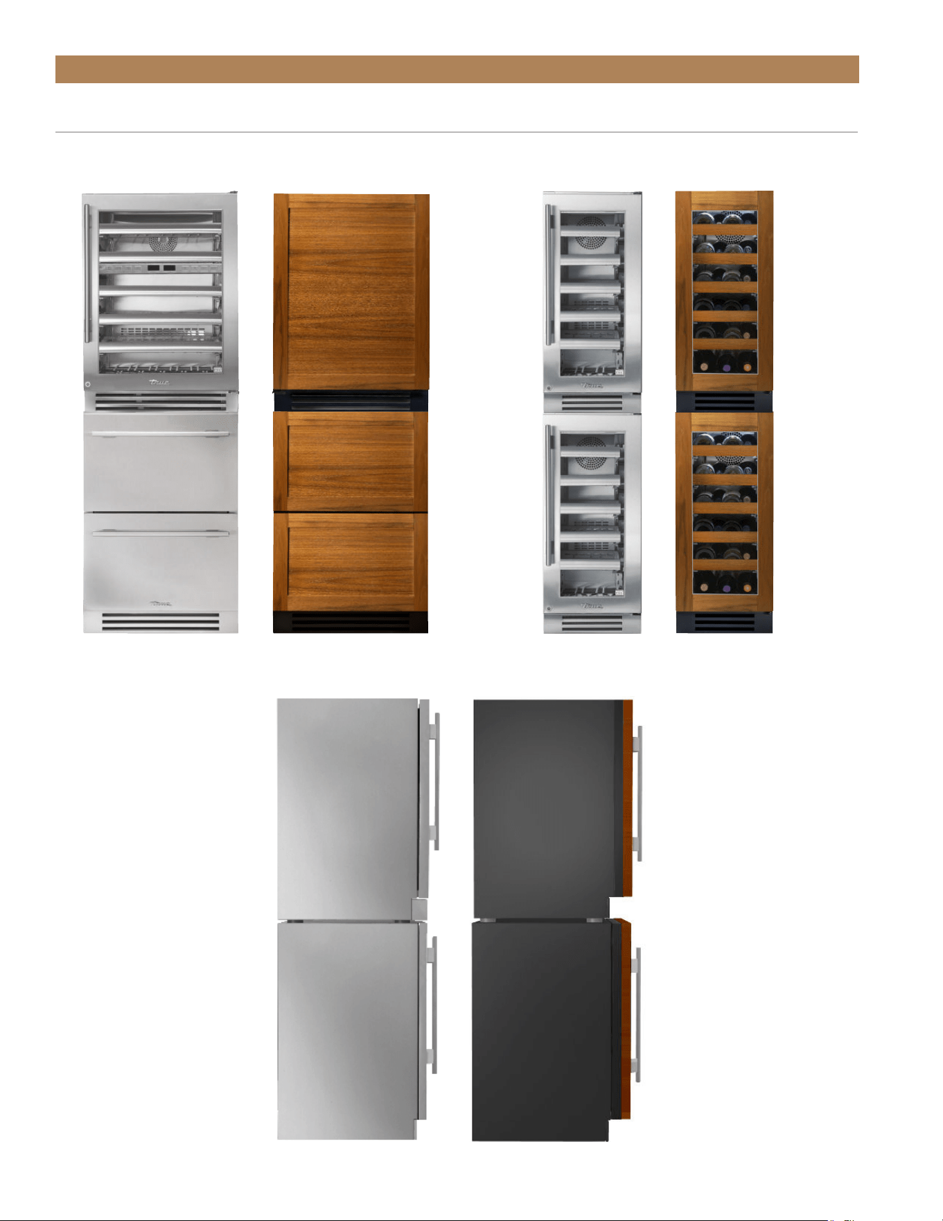
CABINET SETUP
TRUE STACKING KIT
24 INCH
24/15 INCH SIDE VIEW
15 INCH

TEC_TM_156 | REV. G | EN 10/23/2023 Page 37 of 10015 & 24 INCH INSTALL GUIDE
PRIOR TO INSTALL
STACKING KIT INSTALLATION
KIT CONTENTS
• (1) Louver Grill (stainless models)
• (2) Stacking Brackets
• (4) 1/4" Hex Head Screws
REQUIRED TOOLS
Required tools include (but may not be limited to)
the following:
• Floor protector
• Level
• 1/4" Hex Head Driver
• Drill
RECOMMENDED – This procedure may
require assistance.
RECOMMANDÉ – Cette procédure peut
nécessiter une assistance.
WARNING – Units may pose a tipping
hazard during stacking kit installation
or when moving the stacked units.
ATTENTION – Les unités peuvent
présenter un risque de basculement lors
de l’installation du kit d’empilage ou lors
du déplacement des unités empilées.
PROCEDURE
1. Position the floor protector near the final
installation location.
2. Uncrate the appliances. Secure the shelving,
doors, and drawers.
3. Install the anti-tip brackets (see "Anti-Tip Bracket
Installation" on page 45). Verify the brackets are
correctly positioned.
4. Carefully place the upper appliance on the lower
appliance.
NOTE: DO NOT LIFT THE CABINET BY
THE COUNTERTOPS, DOORS, DRAWERS,
OR GRILLS. THIS STEP MAY REQUIRE
ASSISTANCE.
5. Level the upper appliance.
6. Align the upper appliance with the lower
appliance's sides and back.
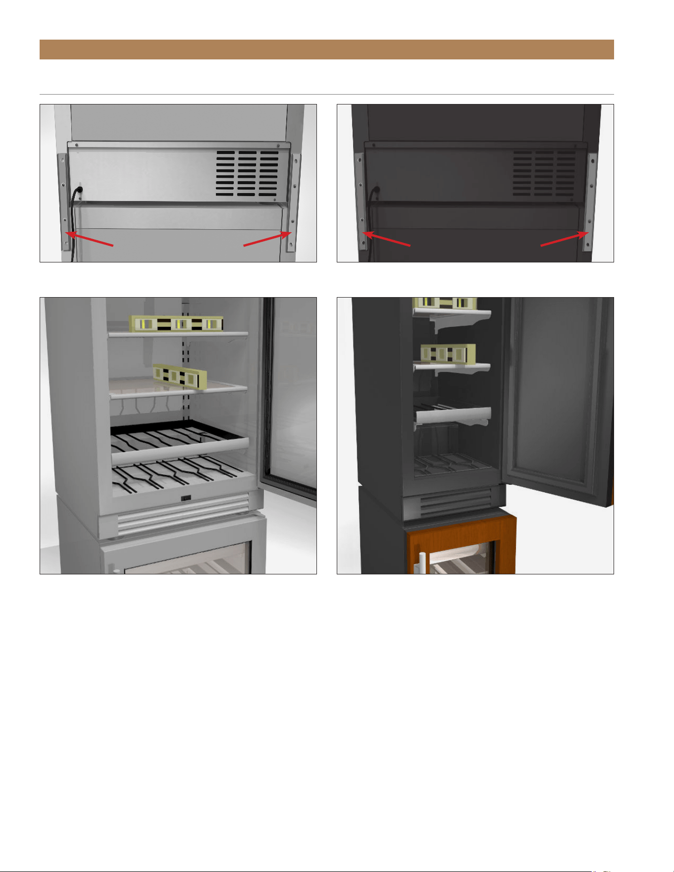
7. Install the rear stacking brackets. See fig. 1.
8. Position the stacked units in the final installation
location.
9. Verify the level of both appliance's. Adjust the
leveling legs as needed. See fig. 2.
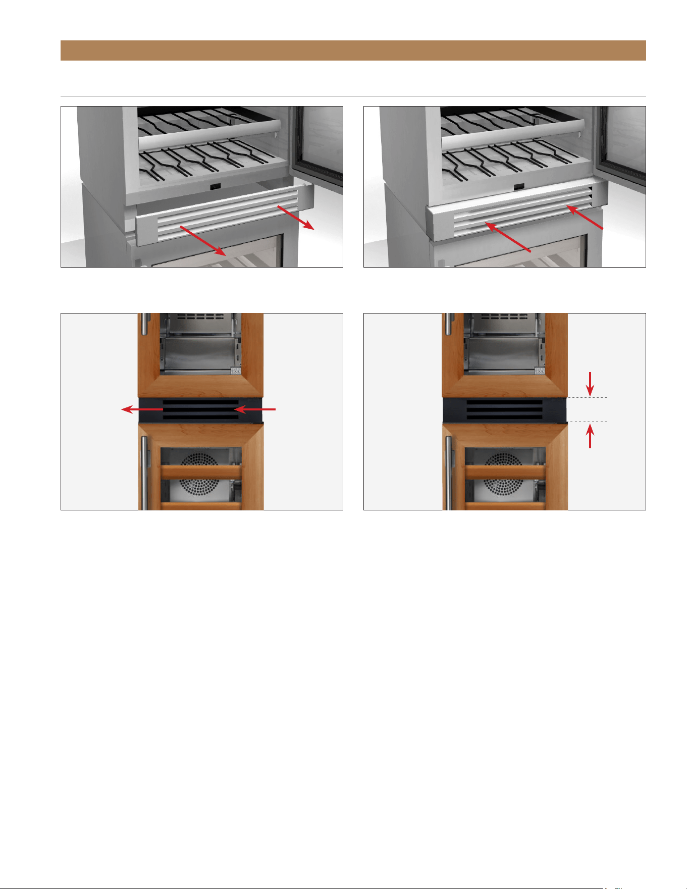
10. Remove the upper appliance's kickplate. See fig. 3.
11. Install the louver grill. See figs 4-6.
NOTE: Be sure to consider air flow when adding a
panel to the grill or door.
TRUE RESIDENTIAL
®
TEC_TM_156 | REV. G | EN10/23/2023Page 38 of 100
PRIOR TO INSTALL
STACKING KIT INSTALLATION (CONT.)
STACKING BRACKETS STACKING BRACKETS
FIG. 1.
The rear stacking brackets.
FIG. 2.
Verify the level front-to-back and side-to-side.
TEC_TM_156 | REV. G | EN 10/23/2023 Page 39 of 10015 & 24 INCH INSTALL GUIDE
PRIOR TO INSTALL
STACKING KIT INSTALLATION
FIG. 3.
Remove the kickplate.
FIG. 5.
Airflow direction.
FIG. 4.
Position the provided grill.
FIG. 6.
Approximate distance from the bottom of the top door to the
bottom of the top appliance.
AIR
FLOW
IN
AIR
FLOW
OUT
3-7/16"
(87 mm)
TRUE RESIDENTIAL
®
TEC_TM_156 | REV. G | EN10/23/2023Page 40 of 100
PRIOR TO INSTALLATION
The unit is approved by UL for outdoor installation.
USE OF ADAPTER PLUGS
NEVER USE AN ADAPTER PLUG! An
adapter plug alters the original OEM plug
configuration when connecting it to a
power source.
TRUE will not warranty any refrigerator/ freezer that
has been connected to an adapter plug.
USE OF EXTENSION CORDS
NEVER USE AN EXTENSION CORD! An
extension cord is determined to be any
component that adds length to the original
OEM power cord when connecting it to a
power source.
TRUE will not warranty any refrigerator/ freezer that
has been connected to an extension cord.
• The ice maker should always be plugged into a
dedicated electrical circuit. This provides the best
performance and prevents building wiring circuits
from being overloaded, which could cause a fire
hazard from overheated wires.
• Before your new unit is connected to a power
supply, check the incoming voltage with a voltmeter.
If the recorded voltage is less than the rated voltage
for operation (+/-5%) and amp rating, correct
immediately. Refer to appliance serial label for this
voltage requirement.
• The electrical outlet must be within 36” (914.4 mm)
of the center of the back wall of the ice maker’s
final location. Outlet must be flush with wall and
comply with local electrical codes.
PRIOR TO INSTALLATION
• The wall outlet and circuit should be checked by
a licensed electrician to make sure the outlet is
properly grounded.
• The power cord of this appliance is equipped
with a 3-prong (grounding) plug which mates
with a standard 3-prong (grounding) wall outlet to
minimize the possibility of electric shock hazard
from this appliance. A 115V AC, 60 Hz, 15 amp
circuit breaker and electrical supply are required.
• If the outlet is a standard 2-prong outlet, it is your
personal responsibility and obligation to have it
replaced with the properly grounded wall outlet.
• DO NOT, under any circumstances, cut or remove
the ground prong from the power cord. For personal
safety, this appliance must be properly grounded.
• When moving the ice maker, for any reason, be
careful not to roll over or damage the power cord.
• Repair or replace immediately all power cords that
have become frayed or otherwise damaged. DO NOT
use a power cord that shows cracks or abrasion
damage along its length or at either end.
• If the supply power cord is damaged, it should be
replaced with original equipment manufacturer
(OEM) components. To avoid hazard this should be
done by a licensed service provider.
• NEVER unplug your ice maker by pulling on the
power cord. Always grip plug firmly and pull straight
out from the outlet.
ELECTRICAL INSTALLATION & SAFETY
TEC_TM_156 | REV. G | EN 10/23/2023 Page 41 of 10015 & 24 INCH INSTALL GUIDE
PRIOR TO INSTALLATION
ELECTRICAL INSTALLATION & SAFETY (CONT.)
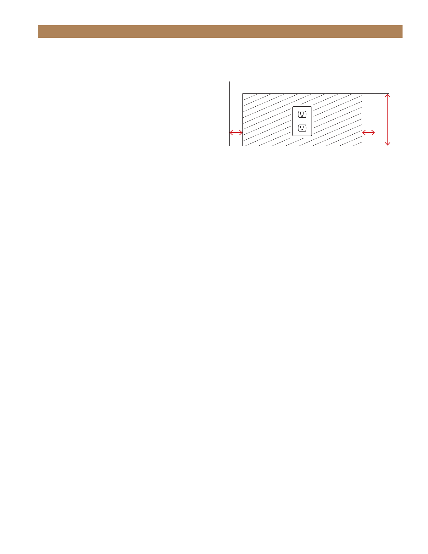
ELECTRICAL OUTLET LOCATION
To minimize the depth of the cutout opening, the
electrical outlet must be positioned as shown below.
Outlet must be flush with wall.
NOTE: COMPRESSOR WARRANTIES ARE
VOID IF THE UNIT IS MORE THAN 84" (2134
MM) FROM PLUG-IN CONNECTION OR IF AN
EXTENSION CORD IS USED.
2"
(51 mm)
2"
(51 mm)
Rear wall of cut out
8"
(203 mm)

TRUE RESIDENTIAL
®
TEC_TM_156 | REV. G | EN10/23/2023Page 42 of 100
NOTES

TEC_TM_156 | REV. G | EN 10/23/2023 Page 43 of 10015 & 24 INCH INSTALL GUIDE
INSTALLATION
PRESERVE THE MOMENT
®
UNCRATING
ANTI-TIP BRACKET INSTALLATION
LEVELING
120° DOOR STOP INSTALLATION
KICKPLATE INSTALLATION
90° DOOR STOP INSTALLATION (OPTIONAL)
TRUE RESIDENTIAL
®
TEC_TM_156 | REV. G | EN10/23/2023Page 44 of 100
INSTALLATION
packing material
REQUIRED TOOLS
• Cutting utensil (utility knife)
• Hammer
• Crowbar
• Phillips head screwdriver
• Floor Protector
PROCEDURE
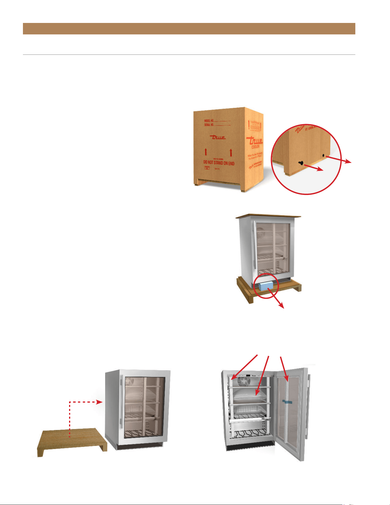
The following procedure is recommended for uncrating
the unit:
1. Remove the outer packaging (cardboard and clear
plastic). See fig. 1.
2. Inspect the unit for concealed damage.
Immediately file a claim with the freight carrier if
there is damage.
3. Cut the plastic band and remove the foam block.
See fig. 2.
NOTE: MOVE THE UNIT AS CLOSE AS
POSSIBLE TO ITS FINAL LOCATION BEFORE
REMOVING THE SKID.
4. Position the floor protector next to the skid.
5. Carefully lift the unit off the skid and place the unit
on the floor protector. See fig. 3.
6. Remove the interior packaging. See fig. 4.
UNCRATING
FIG. 1.
Pull the staples from the skid.
FIG. 2.
Remove the foam block after moving the unit as close as
possible to the final installation location.
FIG. 3.
Carefully move the unit off the skid.
FIG. 4.
Interior packaging locations.
NOTE: KEYS FOR THIS UNIT ARE LOCATED
INSIDE THIS PACKET. THE ANTI-TIP
BRACKET KIT AND DOOR STOP ARE
LOCATED INSIDE THE UNIT.
TEC_TM_156 | REV. G | EN 10/23/2023 Page 45 of 10015 & 24 INCH INSTALL GUIDE
INSTALLATION
ANTI-TIP BRACKET INSTALLATION
KIT CONTENTS
• 2 – Anti-Tip Brackets
• 4 – 3/16" x 2-1/4" Concrete Screws
• 4 – 12 x 2" Phillips Wood Screws
REQUIRED TOOLS
• Floor Protector
• Tape Measure
• Marking Utensil
• 1/8" Drill Bit*
• Phillips Bit Driver or 1/4" Hex-Head Driver
• Drill
*Drill bit type will vary by flooring material.
CAUTION – ALL UNITS OR
STACKED UNITS MUST HAVE
ANTI-TIP BRACKETS INSTALLED.
Install the anti-tip brackets before moving the unit into
its final operating position. Contact a qualified flooring
installer for the best procedure of drilling mounting
holes through your flooring material.
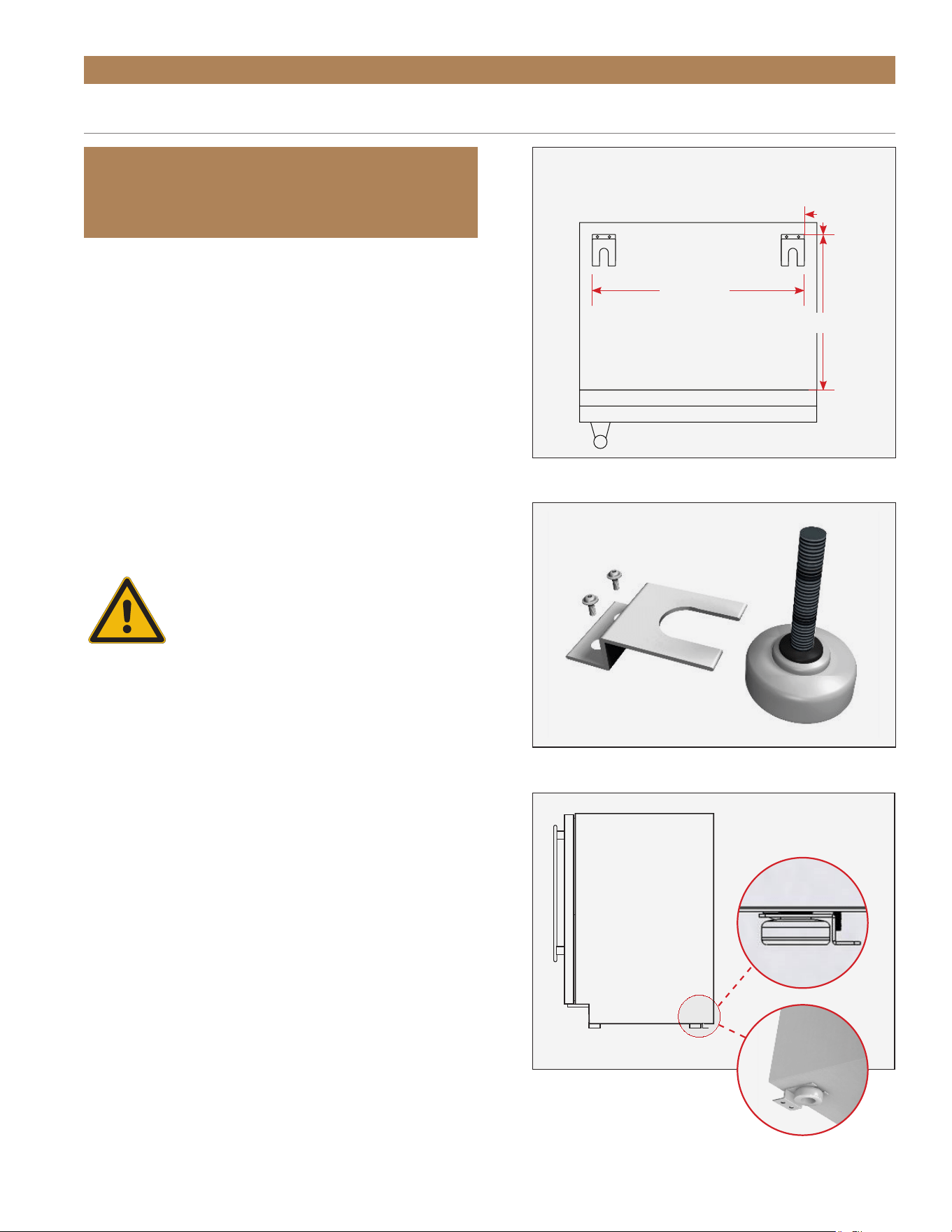
PROCEDURE
1. Place the unit on the floor protector.
2. Determine the final installation location of the unit.
Measure 27/32" (22 mm) inset from the sides
and either 27/32" from the back or 18-1/2"
(470 mm) from the front (measure does not
include the kickplate). See fig. 1.
3. Position the anti-tip brackets and mark the
mounting hole locations.
4. With a 1/8” drill bit, drill pilot holes at the marked
locations.
NOTE: BE SURE TO USE A DRILL BIT
APPROPRIATE FOR YOUR FLOORING
MATERIAL.
IMPORTANT!
ALL FREE STANDING DRAWER OR STACKED
UNITS MUST HAVE ANTI-TIP BRACKETS INSTALLED.
Anti-Tip Bracket (top view)
Back
Front
18-1/2"
22-3/16"
27/32"
FIG. 1.
Top plan view of anti-tip bracket positioning.
FIG. 2.
Securely fasten the anti-tip brackets to the floor.
FIG. 3.
Be sure the rear leveling legs slide into the brackets.
TRUE RESIDENTIAL
®
TEC_TM_156 | REV. G | EN10/23/2023Page 46 of 100
INSTALLATION
ANTI-TIP BRACKET INSTALLATION
(CONT.)
1. With the appropriate provided hardware, install
the anti-tip brackets. See fig. 2.
NOTE: THE CONCRETE SCREWS ARE BLUE.
2. Carefully position the unit in its final installation
location. Be sure the rear leveling legs slide into
the anti-tip brackets. See fig. 3.
NOTE: DO NOT LIFT THE APPLIANCE BY
THE COUNTERTOPS, DOORS, DRAWERS,
OR GRILLS.
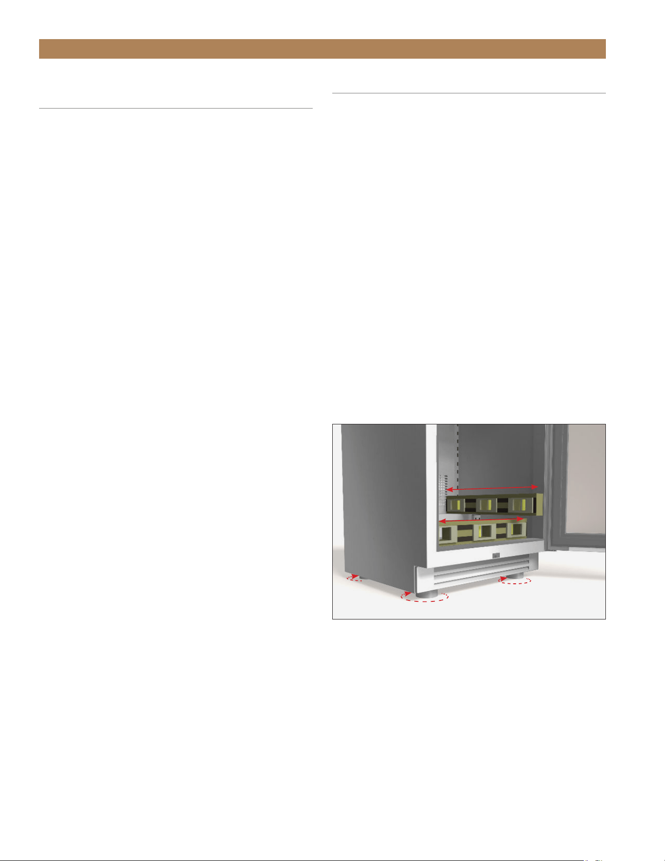
LEVELING
Proper leveling of your TRUE unit is critical to
operating success. Leveling impacts effective
condensate removal and door operation.
With the appliance in the final installation location,
level the unit front-to-back and side-to-side.
PROCEDURE
1. Position the level on the inside floor of the unit
near the doors (the level should be parallel to
appliance front). Level the appliance.
2. Position the level at the inside rear of the appliance
(again, the level should be placed parallel to
cabinet back). Level the appliance.
3. Perform procedures similar to steps 1 and 2 by
placing the level on the inside floor (left and right
side, parallel to the depth of the cooler). Level the
appliance.
TEC_TM_156 | REV. G | EN 10/23/2023 Page 47 of 10015 & 24 INCH INSTALL GUIDE
INSTALLATION
120° DOORSTOP INSTALLATION
All units ship with an optional doorstop. The doorstop
restricts the door from opening past approximately
120° to prevent damage to surrounding cabinetry.
REQUIRED TOOLS
Required tools include (but may not be limited to)
the following:
• Phillips Screwdriver
PROCEDURE
Install the doorstop on the door’s bottom edge.
See figs. 1 and 2.
FIG. 1.
Install the doorstop bracket next to the hinge.
FIG. 2.
Installed doorstop.
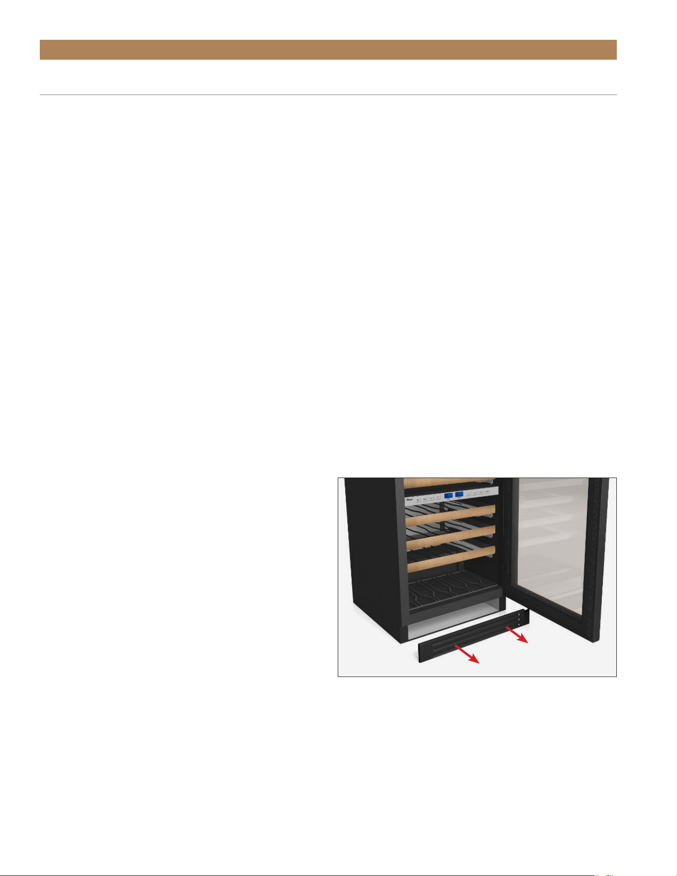
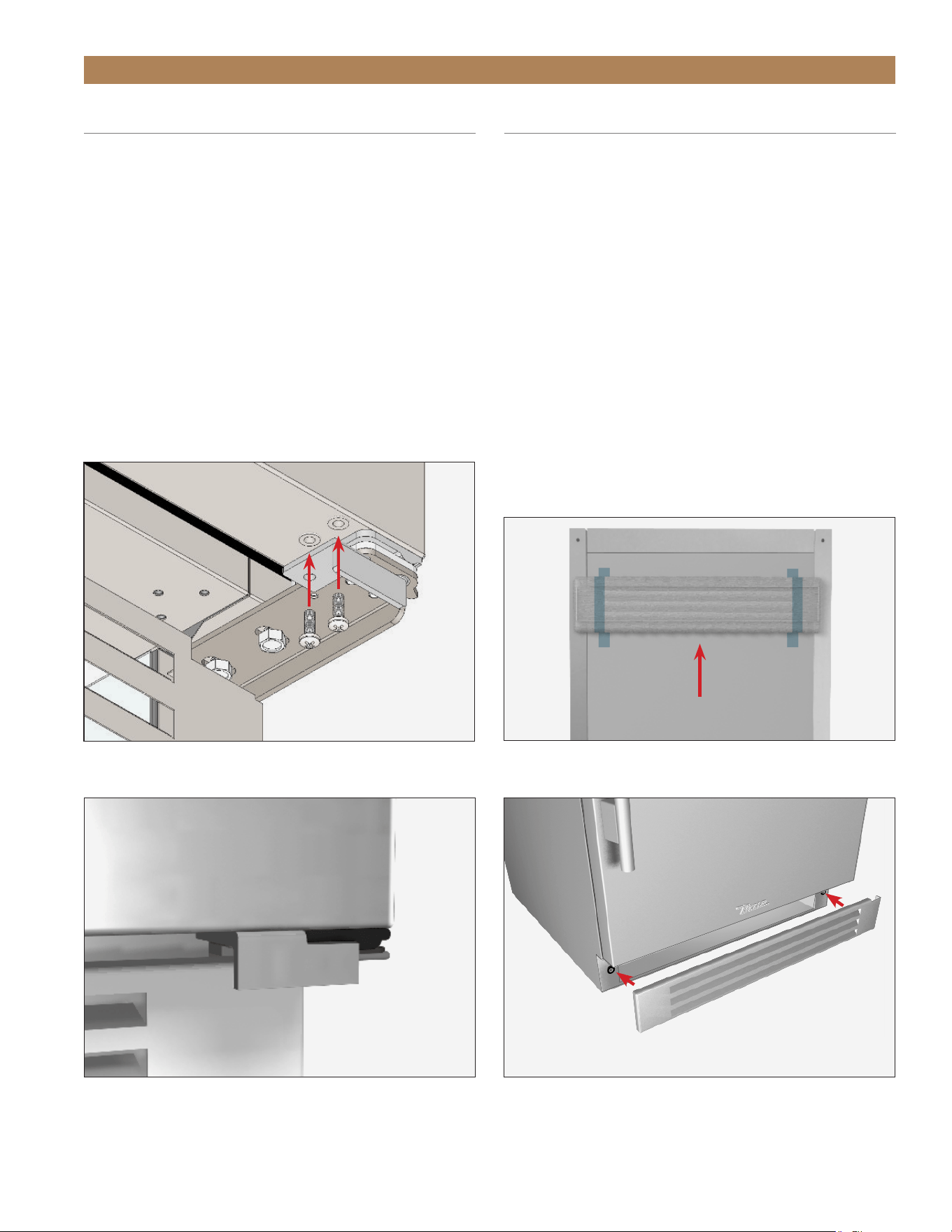
KICKPLATE INSTALLATION
The kickplate is shipped uninstalled to the unit to allow
easy access for leveling. The kickplate attaches to the
unit with magnets at the bottom of the unit.
INSTALLATION
1. After leveling the unit, locate the kickplate taped
to the back of the unit. See fig. 1.
2. Position the kickplate below the door. See fig. 2.
3. Verify the kickplate is correctly aligned. Adjust
as needed.
REMOVAL
Pull the kickplate away from the unit.
FIG. 1.
The kickplate ships taped to the units back.
FIG. 2.
Attach the kickplate to the magnets below the door.
TRUE RESIDENTIAL
®
TEC_TM_156 | REV. G | EN10/23/2023Page 48 of 100
INSTALLATION
90° HINGE INSTALLATION (OPTIONAL)
KIT CONTENTS
• 90° Hinge (left or right)
• Doorstop Bracket (left or right)
REQUIRED TOOLS
Required tools include (but may not be limited to)
the following:
• 3/8" Socket wrench
• Phillips Screwdriver
PROCEDURE
1. Remove the kickplate. See fig. 1.
2. Remove the existing bottom door hinge.
See fig. 2.
NOTE: BE SURE TO SUPPORT THE DOOR
WHILE REMOVING THE HINGE.
3. Carefully slide the door from the top hinge.
See fig. 3.
4. Install the doorstop bracket on the door’s bottom
edge. See fig. 4.
5. Position the door and install the 90° hinge.
See fig. 5.
NOTE: DO NOT COMPLETELY TIGHTEN
THE BOLTS.
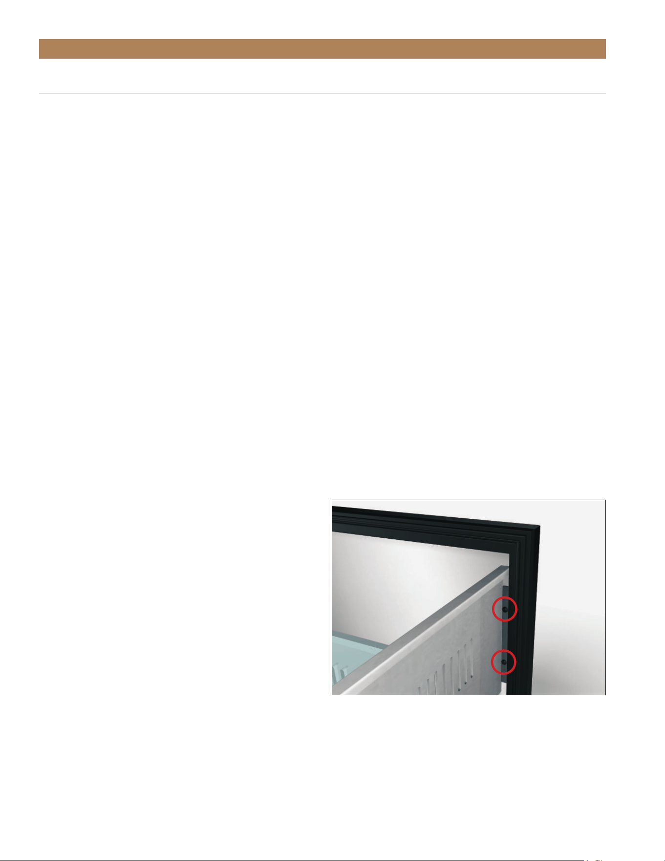
6. Verify the door is aligned with the lock latch and
light switch. See fig. 6. Verify the door closes
correctly and the gasket seals without gaps.
Adjust the door as needed.
7. Tighten the hinge bolts.
FIG. 1.
Pull the kickplate off the magnets.
FIG. 2.
Bottom hinge bolt locations.
FIG. 3.
Lower the door off the top hinge.
TEC_TM_156 | REV. G | EN 10/23/2023 Page 49 of 10015 & 24 INCH INSTALL GUIDE
INSTALLATION
90° HINGE INSTALLATION (OPTIONAL)
FIG. 4.
Doorstop bracket installed on door.
FIG. 5.
Installed 90° hinge kit.
FIG. 6.
Lock latch and light switch locations.

TRUE RESIDENTIAL
®
TEC_TM_156 | REV. G | EN10/23/2023Page 50 of 100
NOTES

TEC_TM_156 | REV. G | EN 10/23/2023 Page 51 of 10015 & 24 INCH INSTALL GUIDE
APPLIANCE SETUP
PRESERVE THE MOMENT
®
GLASS SHELF ADJUSTMENT
WINE RACK ADJUSTMENT
DRAFT STANDARD INSTALL & HOOK UP
DRAFT STANDARD INSTALL (COUNTERTOP)
DRIP TRAY INSTALLATION
DISPENSING PRESSURE
TAPPING
DRAFT BEER PROBLEMS
CHANGING CO
2
GAS CYLINDER
CO
2
REGULATOR PRESSURE ADJUSTMENT
DRAFT TOWER CLEANING
TRUE RESIDENTIAL
®
TEC_TM_156 | REV. G | EN10/23/2023Page 52 of 100
APPLIANCE SETUP
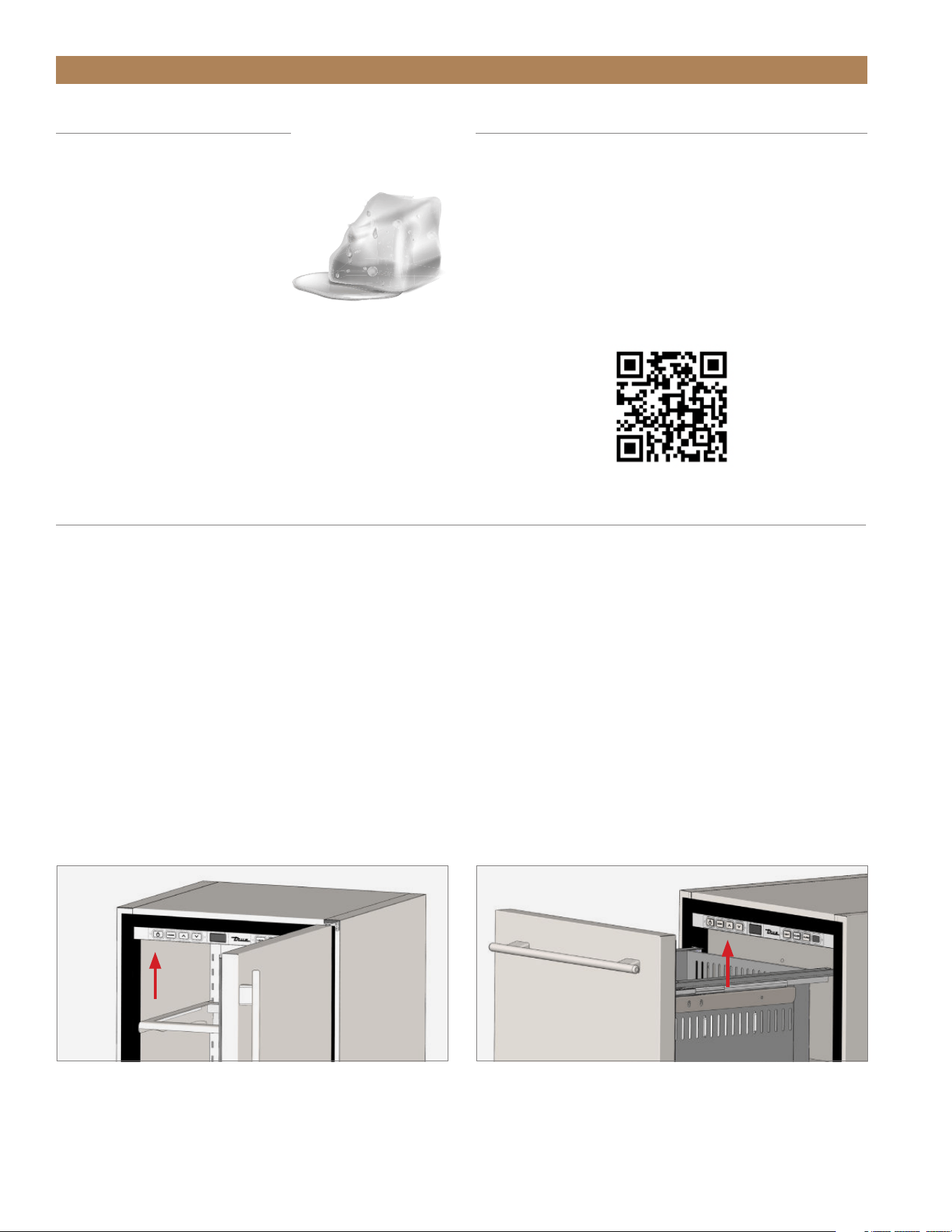
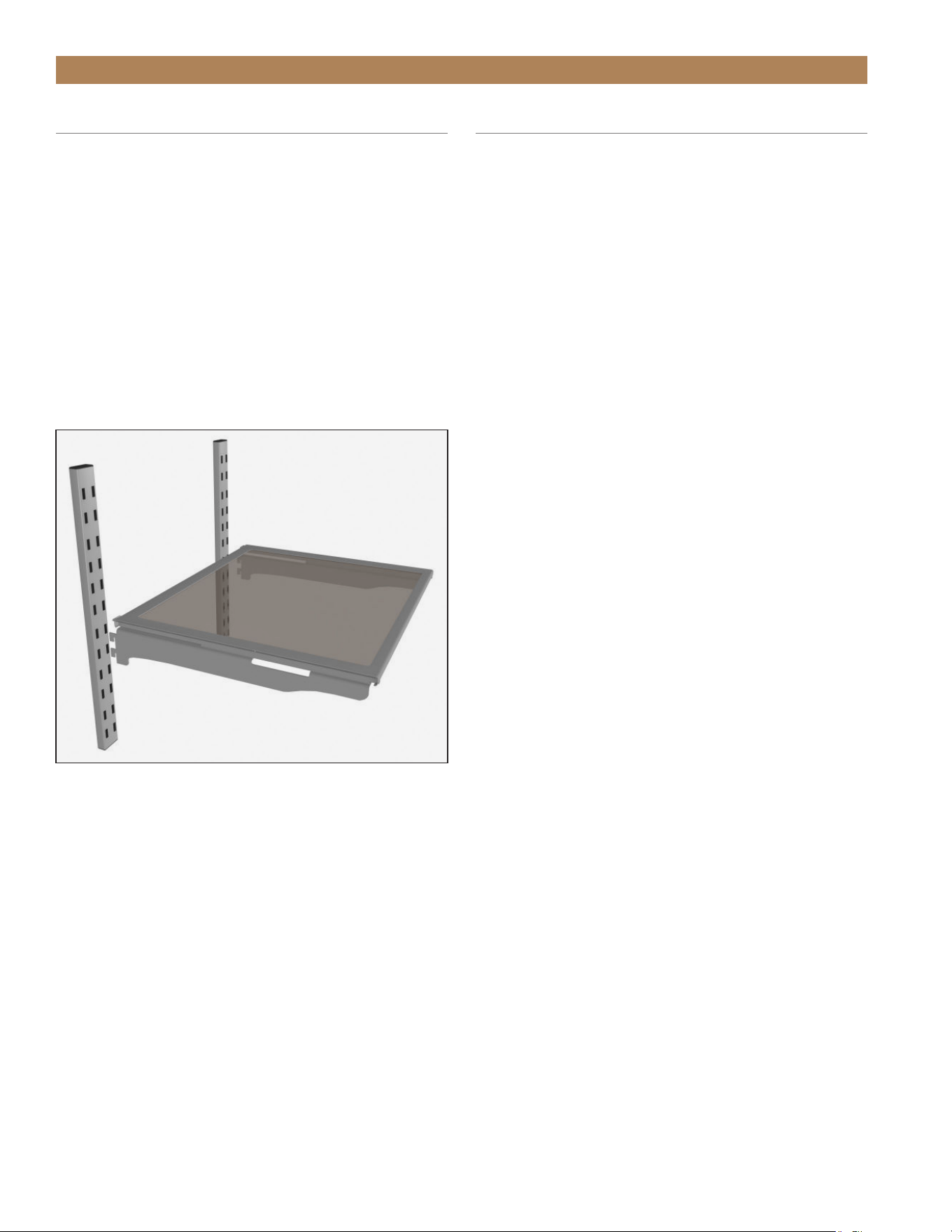
GLASS SHELF ADJUSTMENT
The mounting brackets / glide assemblies ship installed
on the glide out glass shelves.
INSTALLATION
Hook the mounting brackets / glide assemblies into the
pilasters. See fig. 1.
REMOVAL
Carefully lift the shelf assembly up. Then, pull the shelf
assembly forward. See fig. 1.
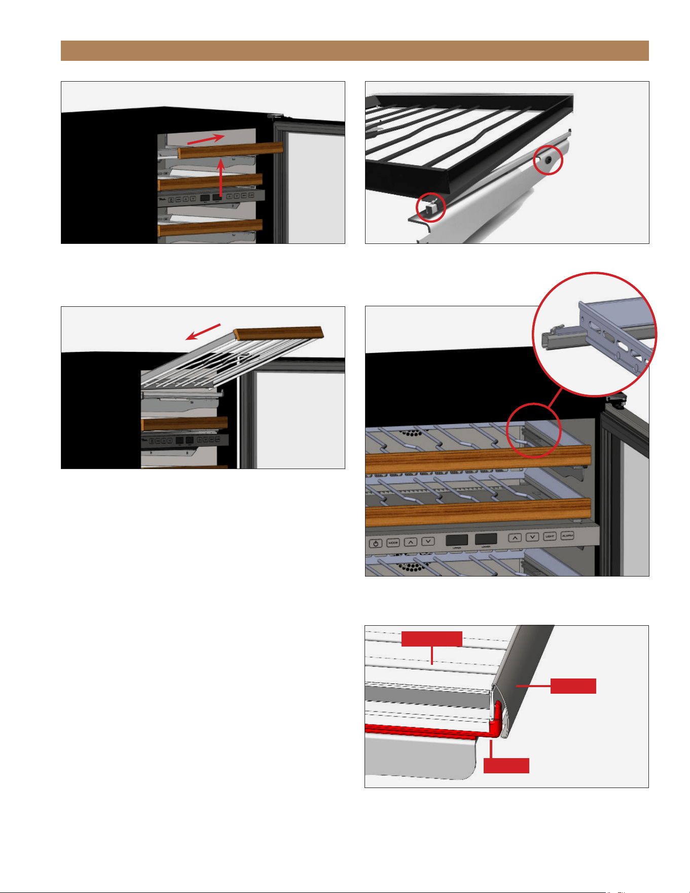
WINE RACK ADJUSTMENT
Wine racks in TBC, TWC, and TWZ-DZ consist of two
mounting bracket / glide assemblies and the wire wine
rack.
REMOVAL
1. Gently lift the wine rack handle and pull the wine
rack forward. See fig. 1.
2. Lift the mounting brackets and pull the brackets
forward.
3. Repeat steps 1 and 2 as needed.
INSTALLATION
1. Hook the mounting bracket with the anti-vibration
bumpers (see fig. 2) into the hinge-side pilaster.
2. Hook the remaining mounting bracket into the
other pilaster.
3. Position the wine rack on the slides and carefully
push the wine rack towards the back of the unit.
See fig. 3.
NOTE: BE SURE THE WINE RACK SITS
UNDER THE SLIDES’ REAR TABS. SEE FIG.
4.
4. Repeat steps 1-3 as needed.
CORRECT FIT
The glide’s front tab must fit securely in the gap
between the handle and the rack. See fig. 5. If the
fit is too tight, loosen the screws on the back of the
handle to increase the gap.
The wine shelves are held securely by the anti-
vibration bumpers. If there is too much play side-to-
side, tighten the bumpers against the compartment
walls by rotating them with your fingers.
FIG. 1
. Slide the mounting bracket tabs into the pilaster.
TEC_TM_156 | REV. G | EN 10/23/2023 Page 53 of 10015 & 24 INCH INSTALL GUIDE
APPLIANCE SETUP
FIG. 2.
Be sure the anti-vibration bumpers are on the hinged side.
FIG. 1.
Lift and pull the wine rack forward.
FIG. 4.
Be sure the wine rack sits under the rear tabs.
FIG. 3.
Slide the wine rack into place.
FIG. 5.
The glide’s front tab goes in the gap between the handle and
rack.
Wine Rack
Glide
Handle
ANTI-VIBRATION
BUMPERS
TRUE RESIDENTIAL
®
TEC_TM_156 | REV. G | EN10/23/2023Page 54 of 100
APPLIANCE SETUP
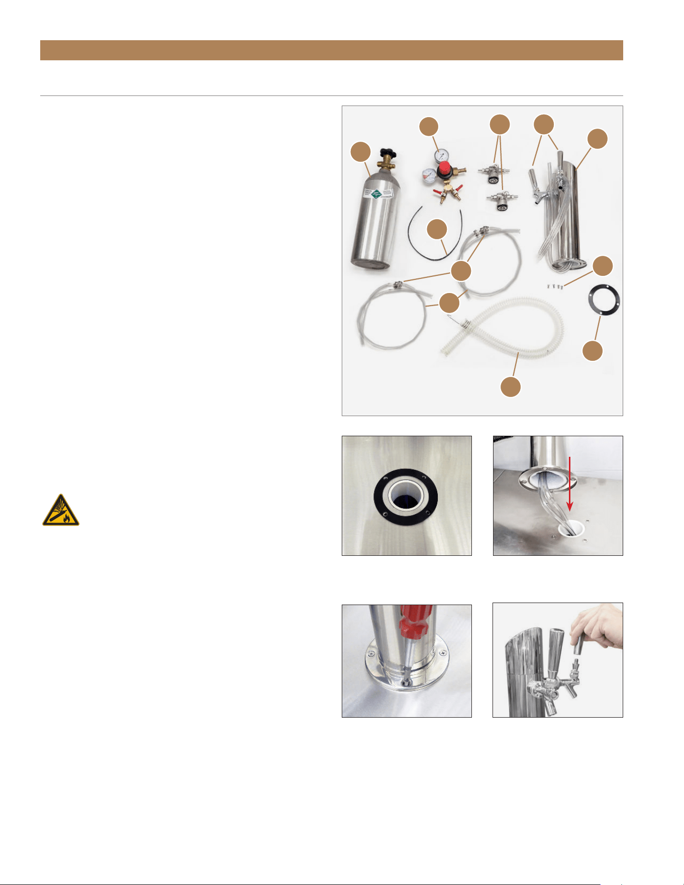
REQUIRED TOOLS
• Phillips Screwdriver
• Adjustable Wrench
KIT CONTENTS
A. CO
2
Tank (Shipped empty. Fill before use)
B. Draft Standard*
C. Draft Standard Screws
D. Draft Standard Handles*
E. CO
2
Pressure Regulator
(single version/double version)
F. Chill Hose**
G. Rubber Washer
H. CO
2
Hoses*
I. Hose Clamps
J. Safety strap
K. Beer Tapper (Sankey, low profile tapper)
*Double draft standard kit shown.
**Located inside the appliance.
DRAFT STANDARD INSTALLATION & HOOK UP
WARNING! – CONTENTS UNDER
PRESSURE. TAKE CARE WHEN
HANDLING FILLED CO₂ TANKS. IF
UNFAMILIAR WITH USING CO₂ TANKS
AND/OR REGULATORS, SEEK INFORMATION
FROM YOUR LOCAL DISTRIBUTOR OR BREWER
REPRESENTATIVE BEFORE PROCEEDING.
PROCEDURE
1. Position the rubber gasket over the mounting holes
in the appliance countertop. See fig. 1.
2. Run the beer line(s) through the hole and into the
appliance. See fig. 2.
3. With the provided hardware, install the draft
standard. See fig. 3.
4. Install the draft standard handle(s). See fig. 4.
5. Remove the draft standard top. See fig. 5.
FIG. 1.
Position the rubber
gasket around the draft tower
hole.
FIG. 2.
Thread the draft standard
lines into the appliance.
FIG. 3.
Secure the draft standard
to the countertop.
FIG. 4.
Screw the handles on.
A
E
B
D K
C
G
I
F
J
H
TEC_TM_156 | REV. G | EN 10/23/2023 Page 55 of 10015 & 24 INCH INSTALL GUIDE
APPLIANCE SETUP
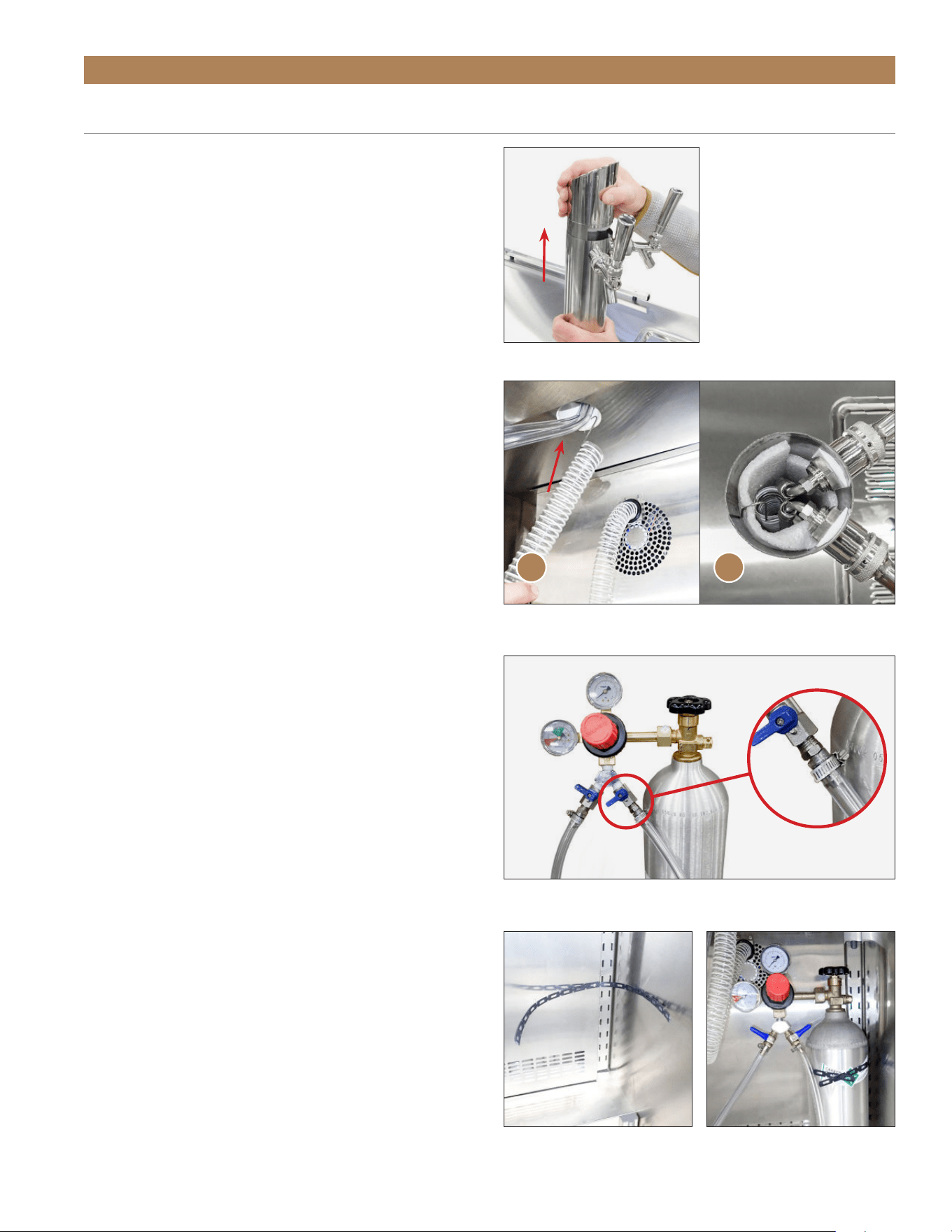
DRAFT STANDARD INSTALL & HOOK UP (CONT.)
6. Hook the chill hose’s clip to the top of the draft
standard insulation sleeve. See fig. 6.
NOTE: DO NOT REMOVE THE INSULATION
SLEEVE FROM THE DRAFT STANDARD.
7. Reinstall the draft standard top.
8. Attach the pressure regulator to the CO₂ cylinder.
See fig. 7.
NOTE: FILL THE CO
2
CYLINDER BEFORE
INSTALLATION. DO NOT LAY CO
2
CYLINDERS
ON THEIR SIDE. DO NOT DROP CO
2
CYLINDERS.
9. With the hose clamp(s), connect the provided clear
vinyl hose(s) to the pressure regulator. See fig. 7.
NOTE: MAKE SURE CLAMP IS ON THE HOSE
PRIOR TO ATTACHING.
10. Install the safety strap inside the appliance.
See fig. 8.
11. Position the CO₂ cylinder inside the appliance.
Then, fasten the safety strap around the cylinder.
See fig. 9.
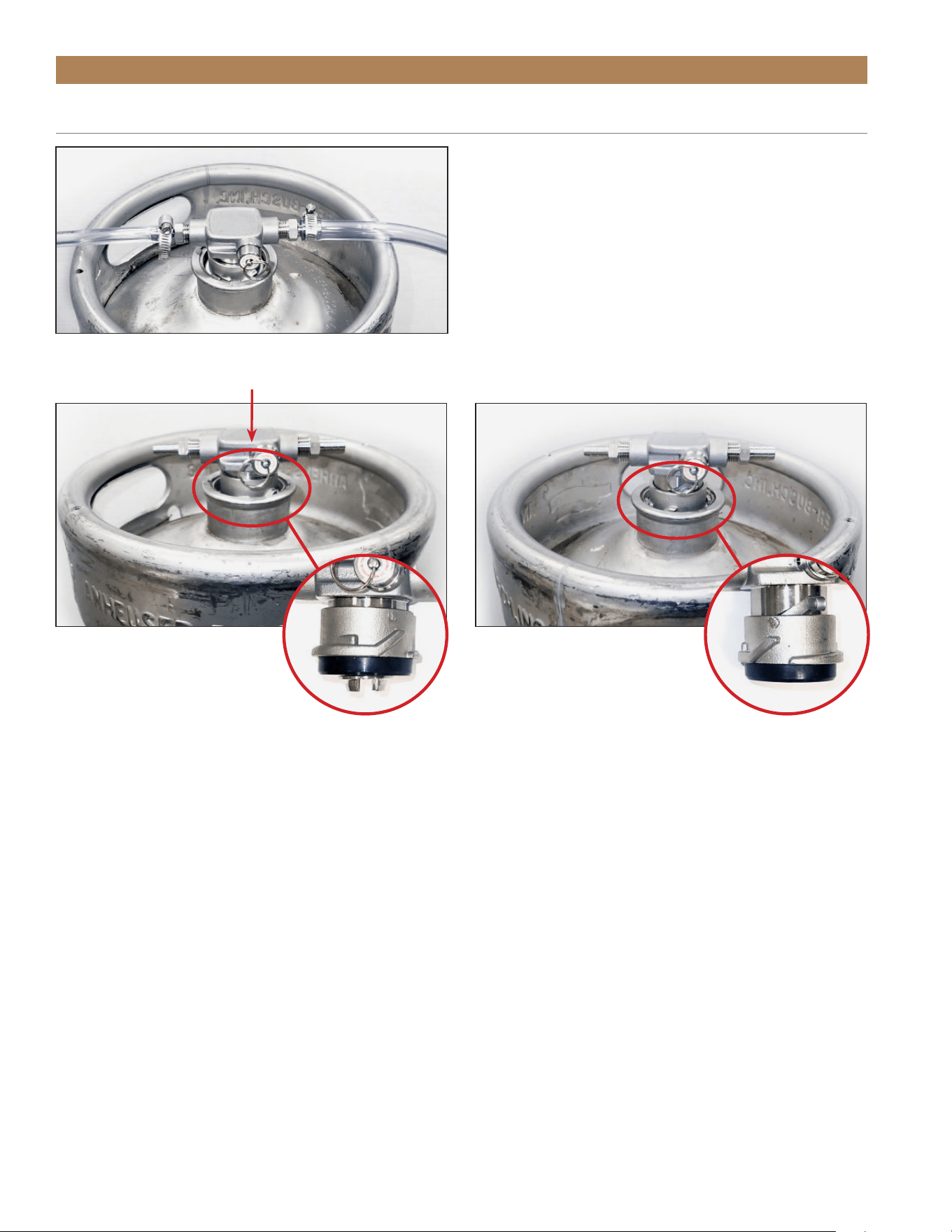
12. Attach the tapper to the keg. See fig. 10.
13. With the hose clamp(s), connect the provided clear
vinyl hose(s) to the tapper’s air inlet.
NOTE: MAKE SURE CLAMP IS ON THE HOSE
PRIOR TO ATTACHING.
14. Pressurize the system and check the connection
points for leaks. If the system leaks, verify all
fittings and clamps are tight and seal correctly.
15. With the hose clamp(s), connect the draft standard
line(s) to the tapper.
NOTE: MAKE SURE CLAMP IS ON THE HOSE
PRIOR TO ATTACHING.
16. Engage the tapper. See fig. 11.
17. Position the keg inside the appliance.
FIG. 5.
Lift the top off the draft standard.
FIG. 6.
Route the chill hose into the draft standard from below (A) and
hook it on the top of the insulation sleeve (B).
FIG. 7.
Installed pressure regulator and air hoses. Be sure the hose
clamps are tightened to prevent leaks.
FIG. 8.
Installed safety strap.
FIG. 9.
Always strap the CO
2
cylinder into the appliance.
A B
TRUE RESIDENTIAL
®
TEC_TM_156 | REV. G | EN10/23/2023Page 56 of 100
DRAFT STANDARD INSTALL & HOOK UP (CONT.)
FIG. 10.
Installed and connected tapper. Be sure the hose clamps are
tightened to prevent links.
FIG. 11.
Engaged tapper vs. disengaged tapper
Push the tapper down and rotate the
tapper clockwise.
Rotate the tapper counterclockwise.
ENGAGED DISENGAGED
APPLIANCE SETUP
TEC_TM_156 | REV. G | EN 10/23/2023 Page 57 of 10015 & 24 INCH INSTALL GUIDE
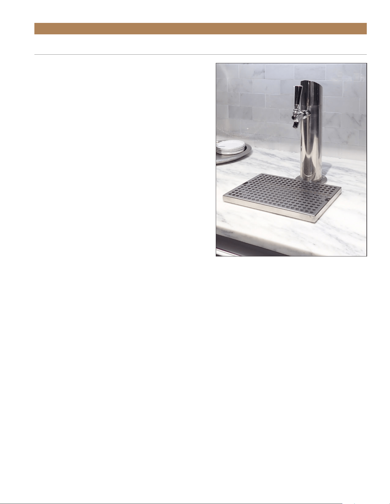
FIG. 1.
Example of countertop draft standard
installation.
APPLIANCE SETUP
DRAFT STANDARD INSTALL (COUNTERTOP)
USE THE FOLLOWING PROCEDURE IF
INSTALLING THE DRAFT STANDARD DIRECTLY
ONTO A COUNTERTOP. SEE FIG. 1.
KIT CONTENTS
• 6" (152.4mm) PVC*
• Coupling*
*Provided by TRUE
REQUIRED TOOLS
• 2-5/8" Hole Saw**
• Drill bit appropriate for #10 screw**
• (4) #10 mounting screws (oval head or
countersunk)**
• Bit Driver
• Drill
• Food Grade Silicone
**Appropriate for the countertop material and
thickness. To be supplied by the installer.
PROCEDURE
1. Determine and mark draft standard and draft
standard mounting hole locations. See figs. 2
and 3.
NOTE: FOR CORRECT INSTALLATION,
COUNTERTOP AND UNIT DRAFT STANDARD
HOLES MUST ALIGN.
2. With a hole saw, carefully drill draft standard hole
through the countertop.
NOTE: BE SURE THE HOLE SAW IS
APPROPRIATE FOR THE COUNTERTOP
MATERIAL.
3. With a drill bit, carefully drill draft standard
mounting holes in the countertop.
NOTE: BE SURE THE DRILL BIT IS
APPROPRIATE FOR THE COUNTERTOP
MATERIAL.
TRUE RESIDENTIAL
®
TEC_TM_156 | REV. G | EN10/23/2023Page 58 of 100
APPLIANCE SETUP
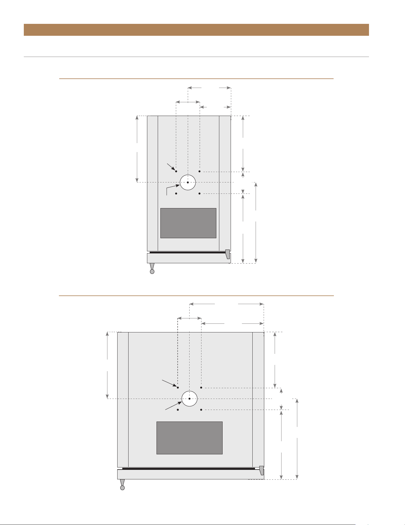
FIG. 2 – 15 INCH MODEL SPECIFICATIONS (TOP VIEW)
FIG. 3 – 24 INCH MODEL SPECIFICATIONS (TOP VIEW)
DRIP
TRAY
7-7/16"
(189 mm)
2-11/16"
(68 mm)
6-3/32"
(155 mm)
10-9/32"
(261 mm)
5/32"
(4 mm)
2-3/8" O.D.
(60 mm)
2-11/16"
(68 mm)
8-15/16"
(227 mm)
13-5/8"
(346 mm)
12-9/32"
(312 mm)
5/32"
(4 mm)
10-23/32"
(272 mm)
DRIP
TRAY
2-11/16"
(68 mm)
11-31/32"
(304 mm)
10-5/8"
(68 mm)
2-11/16"
(68 mm)
2-3/8" O.D.
(60 mm)
9-3/8"
(238 mm)
13-3/4"
(349 mm)
12-13/ 32"
(315 mm)
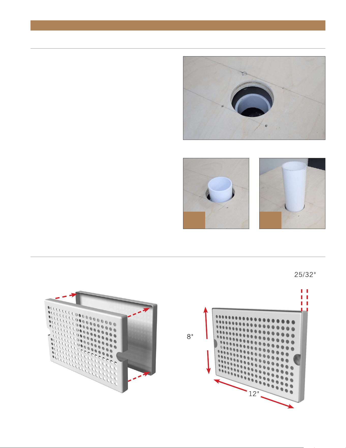
DRAFT STANDARD INSTALL (COUNTERTOP)
TEC_TM_156 | REV. G | EN 10/23/2023 Page 59 of 10015 & 24 INCH INSTALL GUIDE
APPLIANCE SETUP
PROCEDURE (CONT.)
4. Align the unit with the drilled hole. See fig. 4.
5. Install the provided coupling and PVC tubing in
the draft standard holes. See fig. 5.
NOTE: DO NOT USE PVC GLUE.
6. Cut the coupling and PVC tubing flush with the
countertop.
7. Apply food grade silicone to any gaps between
the PVC tubing and the countertop.
NOTE: CLEAN EXCESS SILICONE.
8. Proceed to “Draft Standard Installation & Hook
Up.” Be sure to use draft standard mounting
screws appropriate forcountertop material and
thickness.
FIG. 4.
Align the holes in the appliance with the drilled hole.
FIG. 5.
Cut the coupling (A) and the PVC tubing (B) flush with the
countertop.
DRIP TRAY INSTALLATION
Assemble the drip tray and place it beneath the draft tower spout(s).
A B
(19.8 mm)
(203.2 mm)
(304.8 mm)
DRAFT STANDARD INSTALL (COUNTERTOP)

TRUE RESIDENTIAL
®
TEC_TM_156 | REV. G | EN10/23/2023Page 60 of 100
DISPENSING PRESSURE
DISPENSING PRESSURES DIFFER ACCORDING
TO:
• The type of draft dispensing system
• The length of draft dispensing line
• The actual product – some require more, some
require less
• The temperature of the product
• The pressurizing agent: air pressure, CO
2
or special
blended gases
HELPFUL HINTS ON MAINTAINING THE
CORRECT PRESSURE
• Know which pressurizing agent to use on which
product and why
• Monitor your regulators to ensure applied pressure
remains constant
• Keep equipment in good repair
TAPPING
Do not agitate the kegs unnecessarily. If excessive
agitation occurs allow kegs to settle for 1 to 2 hours
before tapping. Prior to tapping the keg, ensure
that all beer faucet in the serving location are in
the off position. Completely remove the dust cover
(identification cap) from the keg.
DRAFT BEER PROBLEMS
TO MINIMIZE DRAFT BEER PROBLEMS,
ALWAYS FOLLOW THE RECOMMENDED
INSTRUCTIONS FOR TEMPERATURE AND CO
2
PRESSURES FROM YOUR BEER SUPPLIER.
FLAT BEER – Description: Foamy head disappears
quickly. Beer lacks usual zestful brewery fresh flavor
• CO
2
turned off when not in use
• Contaminated air source (associated with
compressed air)
• Greasy glasses
• Not enough pressure
• Pressure shut off during night
• Loose tap or vent connection
• Sluggish pressure regulator
• Obstruction in lines
FALSE HEAD – Description: Large soap-like bubbles,
head dissolves very quickly
• Dry glasses
• Improper pour
• Pressure required does not correspond to beer
temperature
• Coils or direct draw beer lines warmer than beer in
keg
• Small lines into large faucet shanks
• Beer drawn improperly
WILD BEER – Description: Beer, when drawn, is all
foam and not enough liquid beer
• Beer drawn improperly
• Faucet in bad or worn condition
• Kinks, dents, twists or other obstructions in line
• Traps in beer lines
• Beer too warm in kegs or lines
• Too much pressure
• Creeping gauge causing too much pressure
CLOUDY BEER – Description: Beer in the glass
appears hazy. Not clear
• Dirty glass or faucet
• Beer over chilled
• Beer temperature variance in keg. (Beer may have
warmed up at sometime)
• Hot spots in beer lines
• Cutting beer through faucet
• Beer line in poor condition
• Dirty lines
• Beer that has been frozen
BAD TASTE
• Dirty faucet
• Old or dirty beer lines
• Failure to flush beer lines with water after each
empty keg
• Unsanitary conditions at bar
• Foul air or dirt in lines
• Oily air; greasy kitchen air
• Temperature of package too warm
• Dry glasses
APPLIANCE SETUP
TEC_TM_156 | REV. G | EN 10/23/2023 Page 61 of 10015 & 24 INCH INSTALL GUIDE
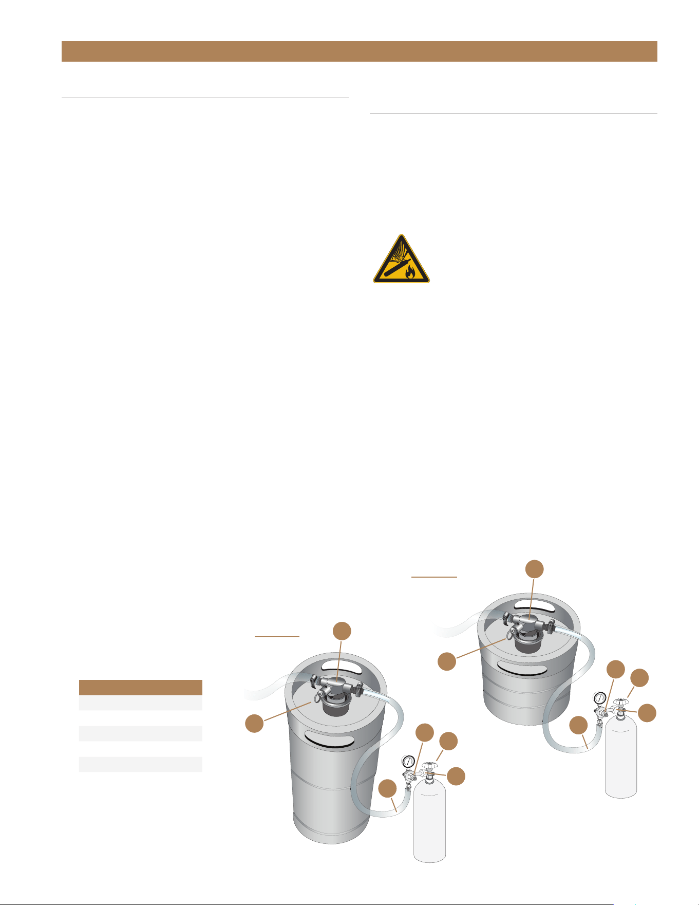
24 INCH
A
B
C
D
E
F
CHANGING CO
2
GAS CYLINDER
CAUTION: ALWAYS FOLLOW THESE
INSTRUCTIONS WHEN YOU REPLACE A CO
2
GAS CYLINDER:
1. Close cylinder valve A.
2. Remove tap head D from the barrel. Pull the
pressure release ring on body of the tap to release
pressure remaining in line. (DO NOT close regulator
shutoff C).
3. Remove or loosen regulator key B by turning
counter clockwise.
4. Remove the regulator from used cylinder at E.
5. Remove the dust cap from new gas cylinder at
outlet E and clear dust from the outlet by opening
and closing valve A quickly using appropriate
wrench.
6. Attach the regulator to the new cylinder at outlet E.
(use new fiber/plastic washer, if required).
7. Completely open valve A.
8. Close valve C.
9. Adjust the regulator key B by turning clockwise
to set pressure. Check setting by opening C and
pulling and releasing the ring F on the pressure
release valve on the body of the tap).
10. Tap the barrel at D with valve C open.
NOTE: DON'T LAY CO
2
CYLINDERS FLAT.
DON'T DROP CO
2
CYLINDERS.
IT REQUIRES 1/2 POUND (0.23 KG) OF
CO
2
TO DISPENSE 1/2 BARREL OF BEER AT
38˚F (3.3˚C) WITH 15 PSI (1.03 BAR) OF
PRESSURE ON THE BARREL.
CO
2
REGULATOR PRESSURE
ADJUSTMENT
Increasing Pressure
1. Close regulator shut-off C.
2. Turn the regulator key B clockwise and adjust
setting.
3. Tap the gauge for an accurate reading.
4. Open regulator shut-off C and draw beer.
WARNING: Contents under pressure.
Take care when handling filled CO
2
tanks. If unfamiliar with using CO
2
tanks
and/or regulators, seek information
from your local distributor or brewer
representative before proceeding.
Decreasing Pressure
1. Close regulator shut-off C.
2. Untap the barrel at D and to bleed line, activate
the tap handle. Leave it in the open position.
3. Slowly open regulator shut-off C and
simultaneously turn regulator key B counter-
clockwise to zero reading.
4. Close regulator shut-off C and set pressure by
turning regulator key B clockwise. Check the
setting by opening and closing valve C.
5. Close the tap head D. (Put in OFF position).
6. Tap the barrel at D and open regulator shut-off C.
APPLIANCE SETUP
15 INCH
A
B
C
D
E
F
PARTS KEY
A Cylinder Valve
B Regulator Key
C Regulator Shut-off
D Tap Head
E CO
2
Cylinder Outlet
F Ring

TRUE RESIDENTIAL
®
TEC_TM_156 | REV. G | EN10/23/2023Page 62 of 100
DRAFT TOWER CLEANING
Regardless of design, draft dispensers must be
cleaned regularly. Flushing the draft dispenser with
only water is not enough to maintain cleanliness. True
recommends cleaning the draft dispenser whenever
changing to a fresh keg.
Clean dispensers ensure your draft beer will be at its
best when served. Although the beer in the barrel
is in excellent condition, the beer can become less
satisfying if drawn through a dirty beer line and faucet.
NOTE: USE CLEANERS APPROVED BY
YOUR BEER SUPPLIER AND FOLLOW THEIR
INSTRUCTIONS. IF YOU ARE USING THE
CLEANING KIT PURCHASED FROM TRUE
FOLLOW THE INSTRUCTIONS BELOW.
Cleaning kit available at
store.trueresidential.com/collections/maintenance-1/
products/beer-line-cleaning-kit
Cleaning solution available at
store.trueresidential.com/collections/maintenance-1/
products/beer-line-cleaning-solution
Prepare Solution:
Add 1/2 ounce (19 grams) of cleaning solution to each
quart of warm water. Fill pump bottle with the mixed
cleaning solution.
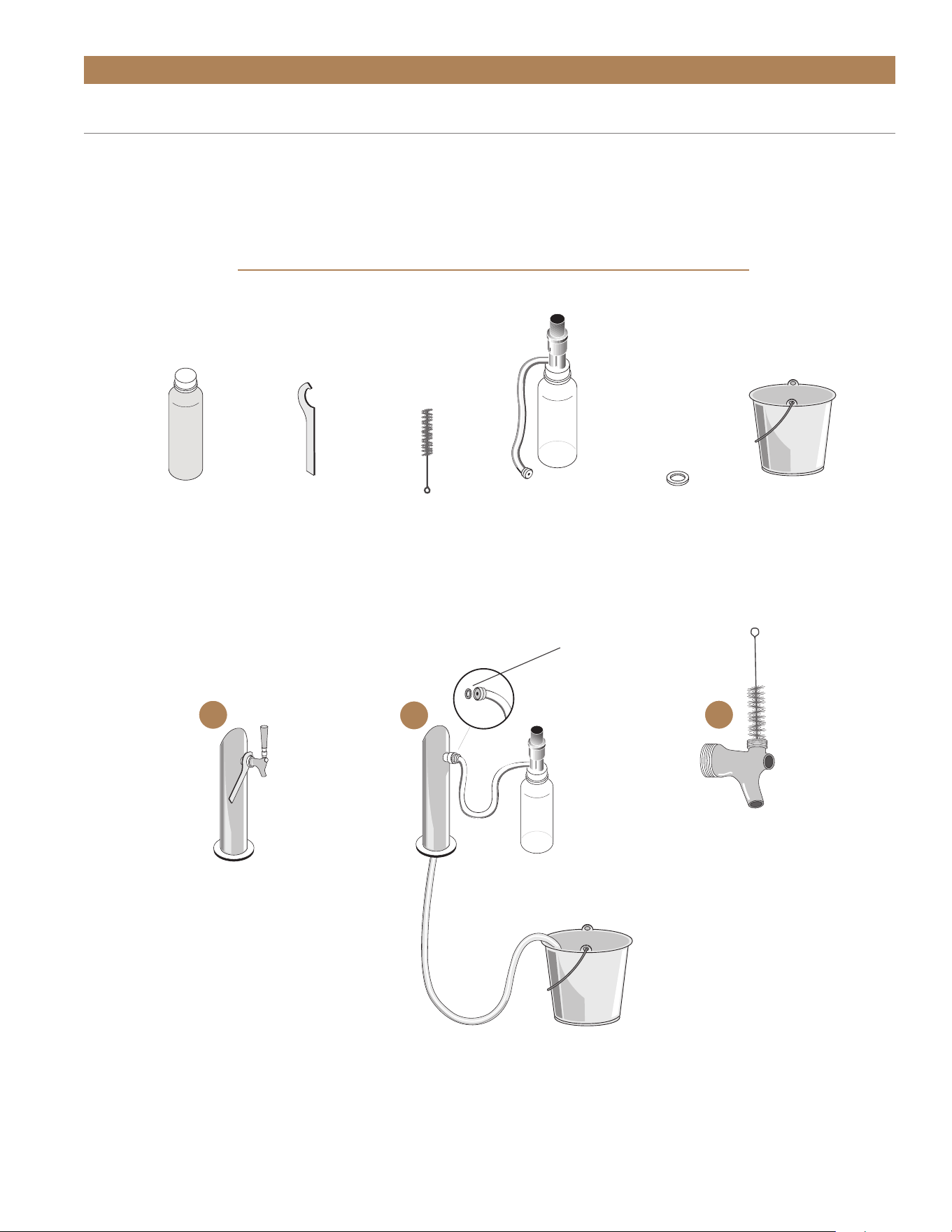
Beer Cleaning instructions:
1. Shut-off the CO
2
at the regulator.
2. Remove the tapping device (keg coupler)
from the keg.
3. Unscrew handle from faucet.
4. Remove beer faucet with spanner wrench
(turn clockwise to remove). See image 1.
5. Put tap and faucet parts in a bucket.
6. Thread hose from pump bottle to beer column tap
outlet (be sure rubber gasket is in place to prevent
leakage) – allow beer line to drain in bucket.
See Image 2.
7. Pump solution from bottle through the beer line(s)
into the bucket. Wait 10 minutes while cleaning
solution works through the lines.
8. Use supplied brush to clean beer faucet parts.
See Image 3.
9. Rinse parts thoroughly.
10. Rinse bucket, pump bottle and hose thoroughly
with clean cool water.
11. Fill pump bottle with clean cool water and pump
through lines until water runs clear. (repeat if
necessary)
12. When crystal clear water comes through, you’re
ready to assemble and reattach faucet and re-tap
the keg.
APPLIANCE SETUP
TEC_TM_156 | REV. G | EN 10/23/2023 Page 63 of 10015 & 24 INCH INSTALL GUIDE
BEER TAP CLEANING KIT REQUIRED TOOLS
BLC SYSTEM
CLEANER
SPANNER
WRENCH
BUCKET AND
FRESH WATER
DRAFT TOWER CLEANING (CONT.)
1
RUBBER
GASKET
2
3
APPLIANCE SETUP
BRUSH
PUMP BOTTLE
AND TUBE
RUBBER
GASKET

TRUE RESIDENTIAL
®
TEC_TM_156 | REV. G | EN10/23/2023Page 64 of 100
NOTES

TEC_TM_156 | REV. G | EN 10/23/2023 Page 65 of 10015 & 24 INCH INSTALL GUIDE
APPLIANCE OPERATION
PRESERVE THE MOMENT
®
NOTE: AN ELECTRONIC CONTROL DISPLAY MAY REFLECT THE
FLUCTUATING TEMPERATURES OF THE REFRIGERATION CYCLE,
NOT THE PRODUCT TEMPERATURE. THE MOST ACCURATE
METHOD TO DETERMINE AN APPLIANCE'S OPERATION IS TO
VERIFY THE PRODUCT TEMPERATURE.
TRUE PRECISION CONTROL
®
OPERATION & APPLIANCE
COMPONENTS (ALL MODELS)
24 INCH REFRIGERATOR & FREEZER
24 INCH DUAL ZONE
24 INCH REFRIGERATOR FREEZER / DRAWERS
15 INCH REFRIGERATOR
HOME ALARM SYSTEM
(DUAL ZONE WINE CABINET ONLY)
TRUE RESIDENTIAL
®
TEC_TM_156 | REV. G | EN10/23/2023Page 66 of 100
APPLIANCE OPERATION
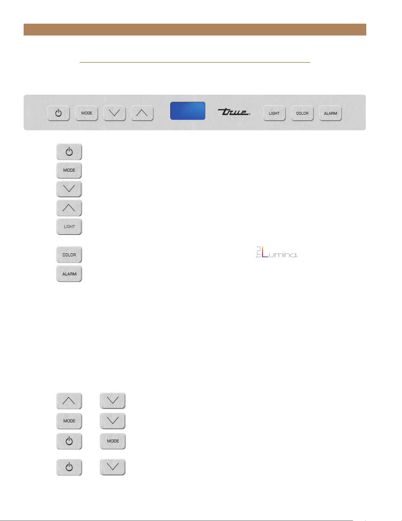
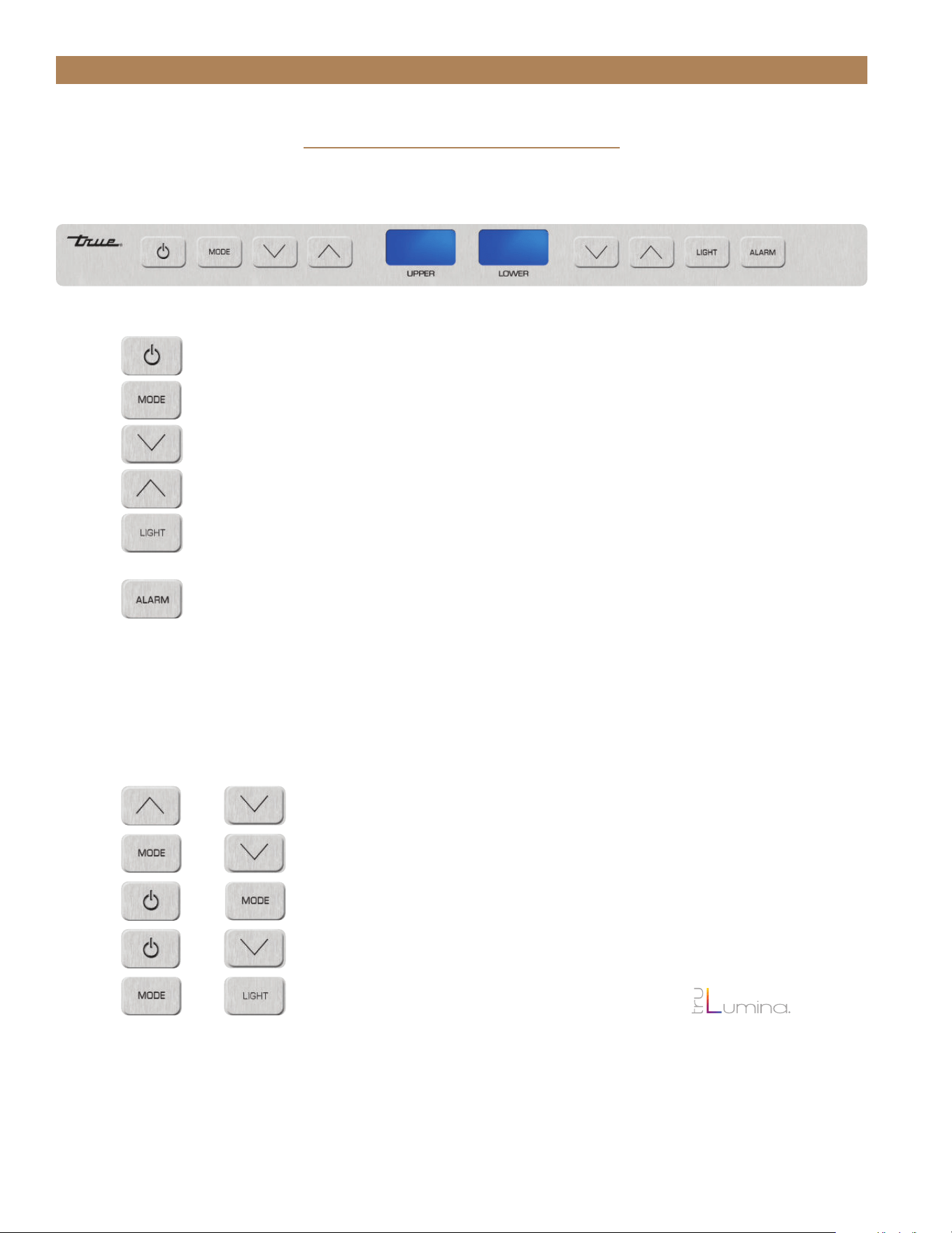
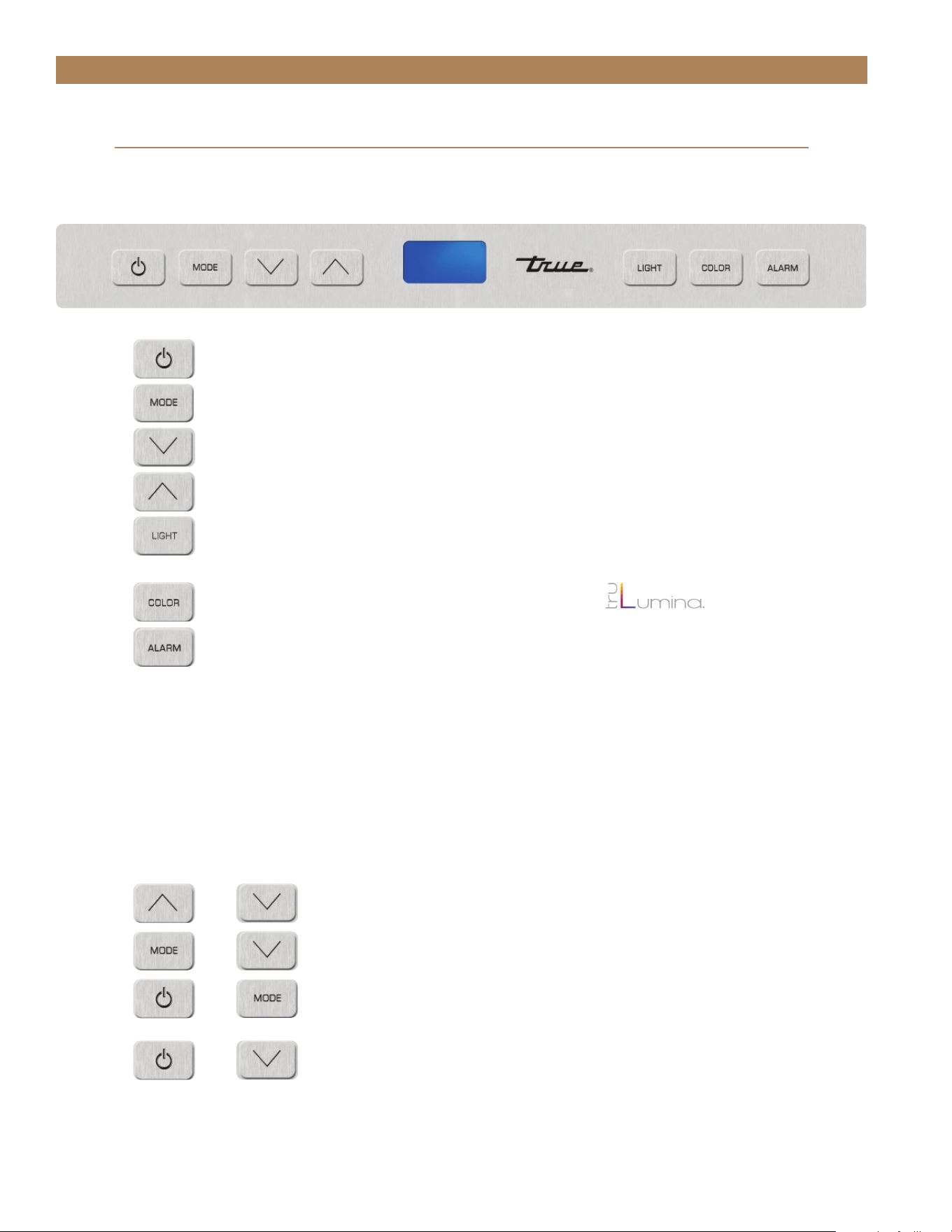
24 INCH REFRIGERATOR & FREEZER
(Freezer not available in glass door)
=
Power unit off / on cuts power to all relays
=
To display set point
=
Press to change set point down
=
Press to change set point up
=
To turn on accent light – This will leave light on all the time even when
the door is closed
=
To switch color LED’s – 14 color TruLumina
®
patent.
=
To turn on door ajar alarm & high temperature alarm – Door ajar alarm
activates after 7 minutes.
• Refrigerator – High temperature alarm activates after one consecutive hour
at or above 50°F.
• Freezer – High temperature alarm activates after one consecutive hour
at or above 20°F. Wine
• Wine Cabinet – High temperature alarm activates after one consecutive
hour at or above 70°F.
=
Lock / Unlock Keypad
=
Sabbath Mode
=
Showroom Mode – Shuts off all refrigeration components.
Displays set point. Lights are fully functional.
=
Toggle °C / °F
+
+
+
+
KEY COMBINATIONS
USER INTERFACE COMMANDS
TEC_TM_156 | REV. G | EN 10/23/2023 Page 67 of 10015 & 24 INCH INSTALL GUIDE
APPLIANCE OPERATION
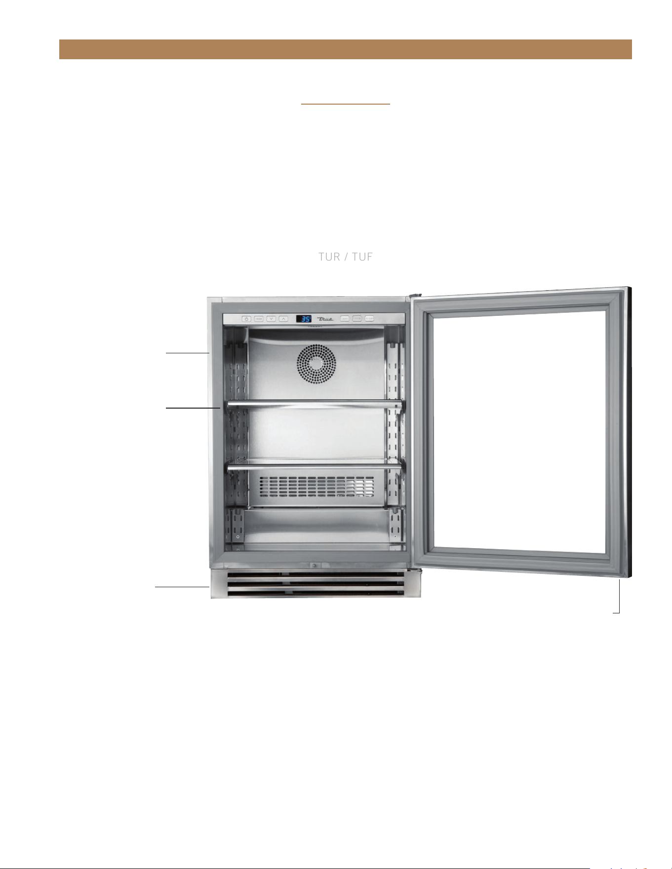
TRUE ALL REFRIGERATOR / FREEZER COMPONENTS
TUR / TUF
REMOVABLE KICK PLATE
FOR EASY CLEANING
DOOR LOCK
ADJUSTABLE STAINLESS
STEEL GLASS SHELVES (2)
LOCATION OF SERIAL TAG
24 INCH
TRUE RESIDENTIAL
®
TEC_TM_156 | REV. G | EN10/23/2023Page 68 of 100
APPLIANCE OPERATION
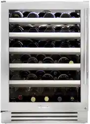
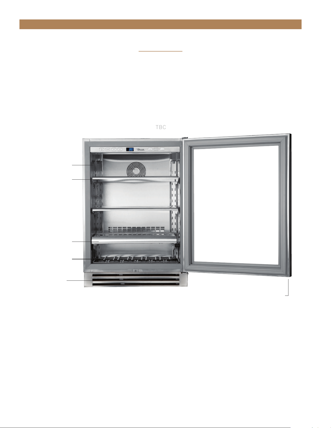
TRUE BEVERAGE CENTER COMPONENTS
TBC
REMOVABLE KICK PLATE
FOR EASY CLEANING
ADJUSTABLE STAINLESS
STEEL GLASS SHELVES (2)
SLIDE OUT WINE SHELF (1)
FLOOR WINE CRADLE (1)
LOCATION OF SERIAL TAG
DOOR LOCK
24 INCH
TEC_TM_156 | REV. G | EN 10/23/2023 Page 69 of 10015 & 24 INCH INSTALL GUIDE
APPLIANCE OPERATION
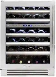
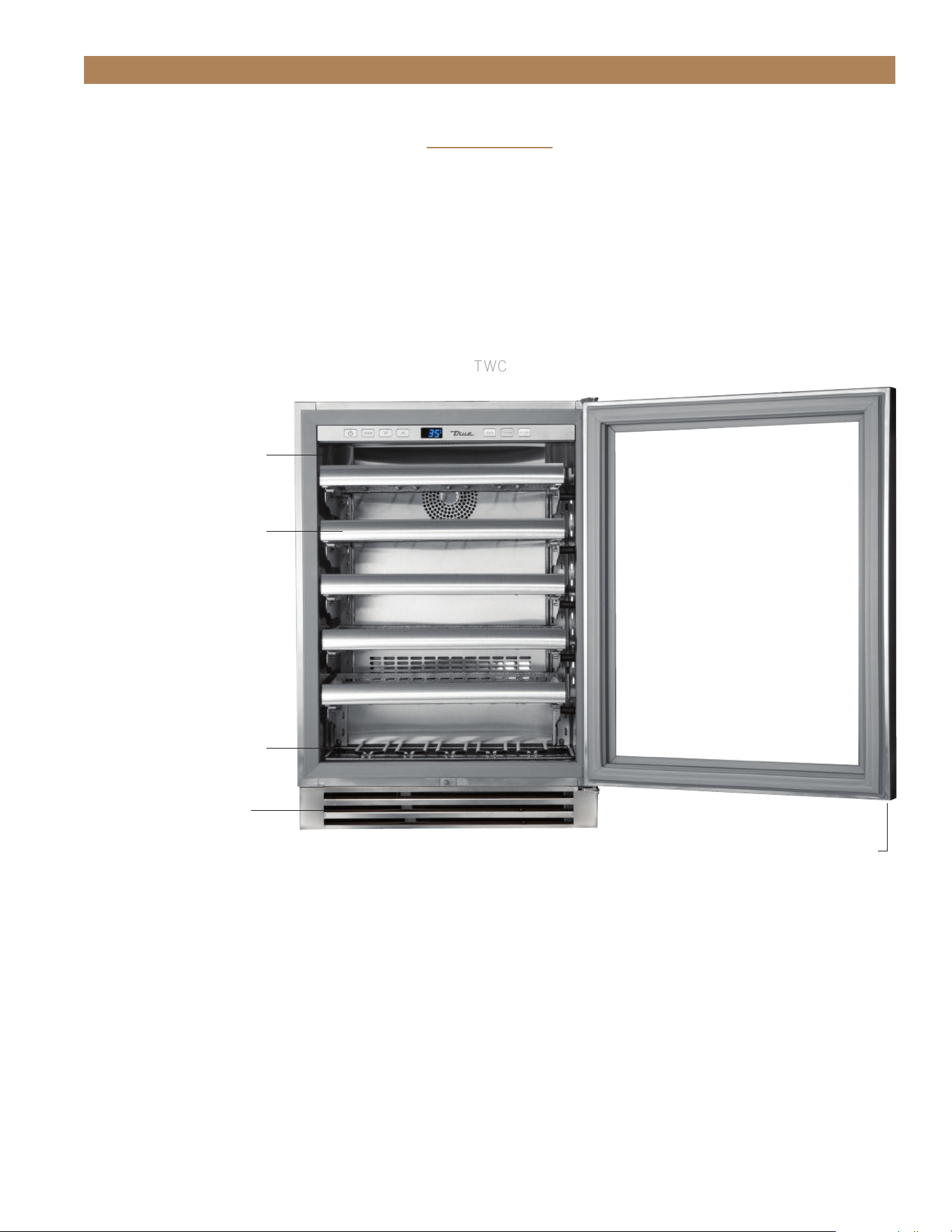
TRUE WINE CABINET COMPONENTS
TWC
REMOVABLE KICK PLATE
FOR EASY CLEANING
FLOOR WINE CRADLE (1)
ADJUSTABLE SLIDE OUT
WINE SHELVES (5)
LOCATION OF SERIAL TAG
DOOR LOCK
24 INCH
TRUE RESIDENTIAL
®
TEC_TM_156 | REV. G | EN10/23/2023Page 70 of 100
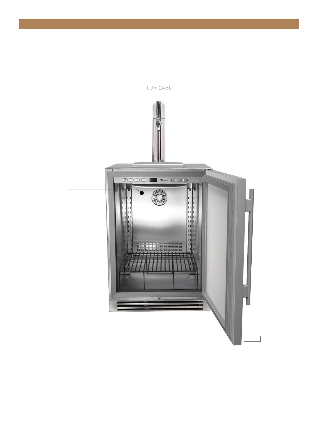
APPLIANCE OPERATION
TRUE BEVERAGE DISPENSER
TUR-24BD
REMOVABLE KICK PLATE
FOR EASY CLEANING
DOOR LOCK
SHELF (1)
FOR USE WITH 1/4
SHORT KEG ONLY
LOCATION OF SERIAL TAG
CHILL HOSE
SPILL GRATE (TOP)
DRIP PAN (BOTTOM)
DRAFT TOWER
24 INCH
TEC_TM_156 | REV. G | EN 10/23/2023 Page 71 of 10015 & 24 INCH INSTALL GUIDE
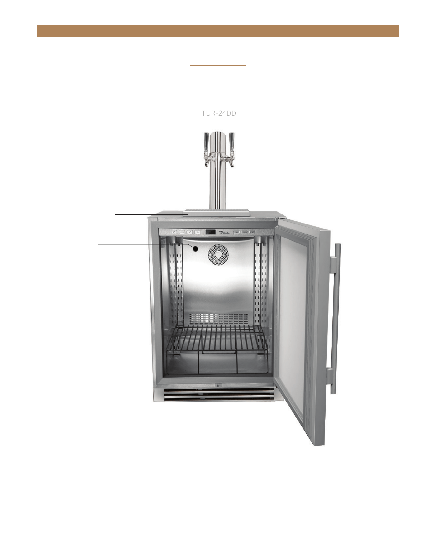
APPLIANCE OPERATION
TRUE DUAL BEVERAGE DISPENSER
TUR-24DD
DOUBLE
DRAFT TOWER
REMOVABLE KICK PLATE
FOR EASY CLEANING
DOOR LOCK
LOCATION OF SERIAL TAG
CHILL HOSE
SPILL GRATE (TOP)
DRIP PAN (BOTTOM)
24 INCH
TRUE RESIDENTIAL
®
TEC_TM_156 | REV. G | EN10/23/2023Page 72 of 100
APPLIANCE OPERATION
KEY COMBINATIONS
=
Lock / Unlock Keypad (UPPER)
=
Sabbath Mode (UPPER)
=
Showroom Mode – Shuts off all refrigeration components.
Displays set point. Lights are fully functional.
=
Toggle °C / °F
=
To switch color LEDs – 14 color TruLumina
®
patent.
+
+
+
+
+
24 INCH DUAL ZONE
USER INTERFACE COMMANDS
=
Power, cuts power to all relays, resumes pulldown.
=
To display set point
=
Press to change set point down, hold to scroll down.
=
Press to change set point up, hold to scroll up.
=
To turn on accent light – This will leave light on all the time even when
the door is closed
=
To turn on door ajar alarm & high temperature alarm – Door ajar alarm
activates after 7 minutes.
• High temperature alarm activates after one consecutive hour
at or above 70°F.
TEC_TM_156 | REV. G | EN 10/23/2023 Page 73 of 10015 & 24 INCH INSTALL GUIDE
APPLIANCE OPERATION
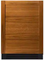
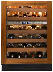
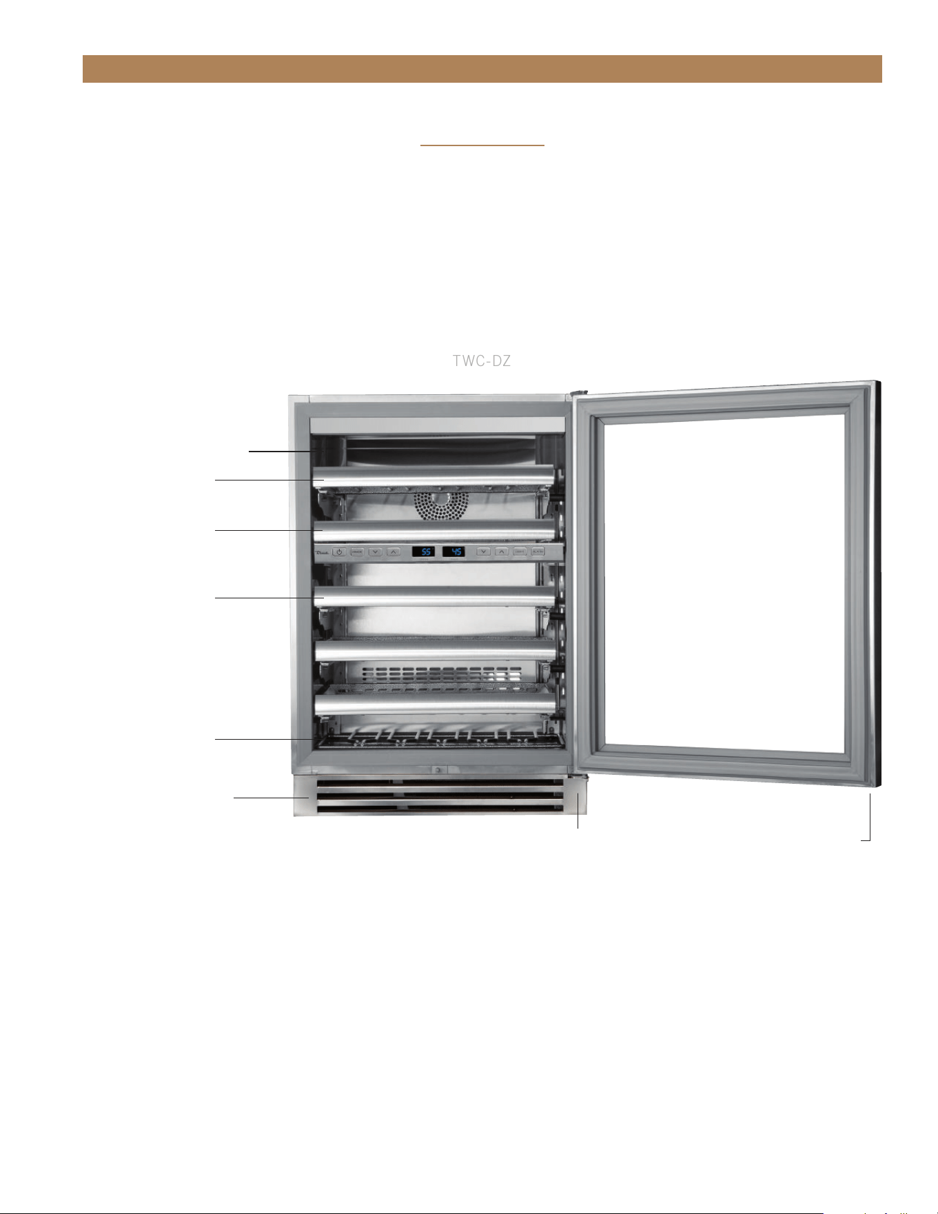
TRUE WINE CABINET - DUAL ZONE COMPONENTS
TWC-DZ
REMOVABLE KICK PLATE
FOR EASY CLEANING
HOME
SECURITY
TIE IN
REMOVABLE WINE
CRADLE (1)
NON-ADJUSTABLE
SHELF (1)
FULLY ADJUSTABLE
WINE SHELF (1)
FULLY ADJUSTABLE
WINE SHELVES (3)
LOCATION OF SERIAL TAG
DOOR LOCK
24 INCH
TRUE RESIDENTIAL
®
TEC_TM_156 | REV. G | EN10/23/2023Page 74 of 100
APPLIANCE OPERATION
24 INCH REFRIGERATOR / FREEZER DRAWERS
=
Power unit off / on cuts power to all relays
=
To display set point
=
Press to change set point down
=
Press to change set point up
=
To turn on accent light – This will leave light on all the time even when
the door is closed
=
To switch color LED’s – 14 color TruLumina
®
patent.
=
To turn on door ajar alarm & high temperature alarm – Door ajar alarm
activates after 7 minutes.
• Refrigerator – High temperature alarm activates after one consecutive hour
at or above 50°F.
• Freezer – High temperature alarm activates after one consecutive hour
at or above 20°F.
=
Lock / Unlock Keypad
=
Sabbath Mode
=
Showroom Mode – Shuts off all refrigeration components.
Displays set point. Lights are fully functional.
=
Toggle °C / °F
+
+
+
+
KEY COMBINATIONS
USER INTERFACE COMMANDS
TEC_TM_156 | REV. G | EN 10/23/2023 Page 75 of 10015 & 24 INCH INSTALL GUIDE
APPLIANCE OPERATION
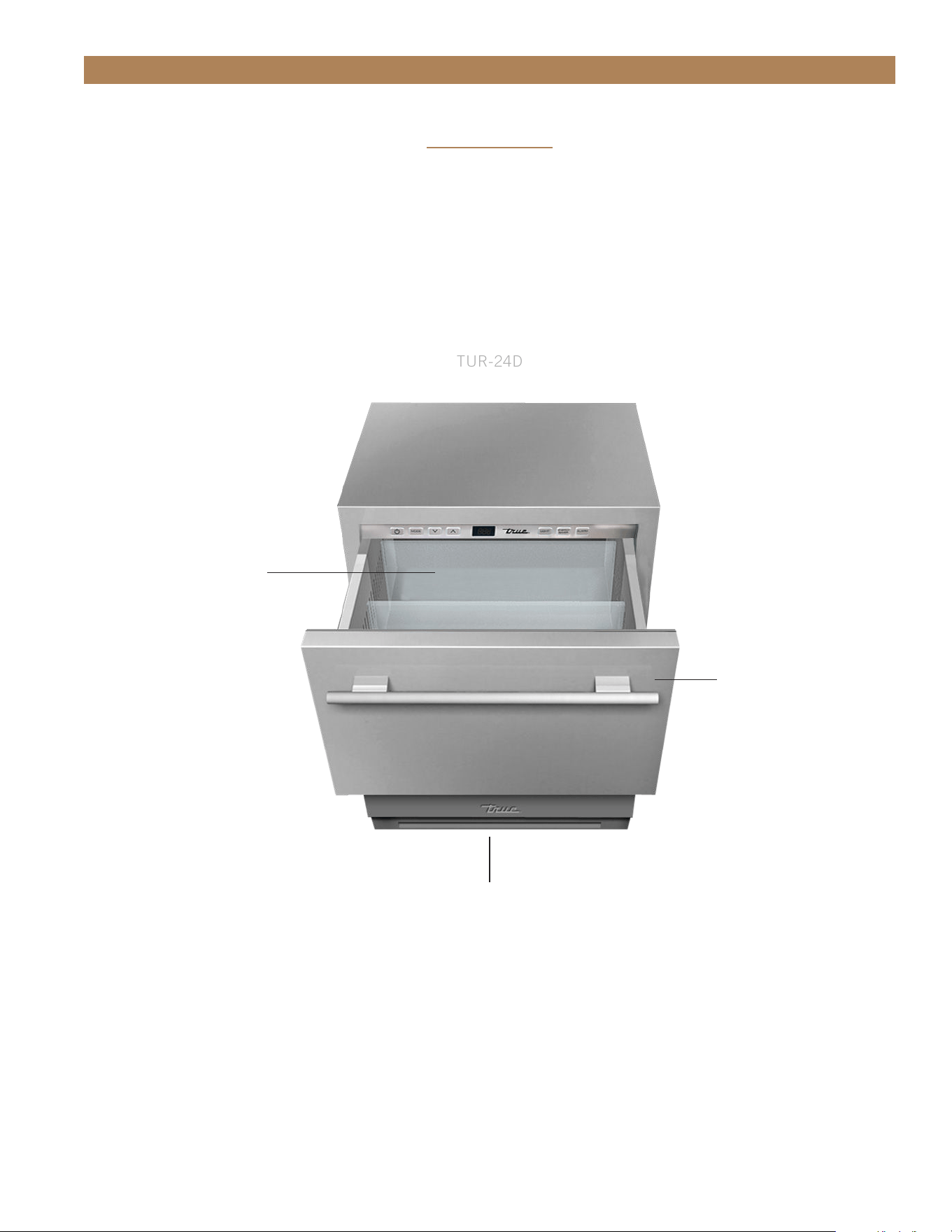
TRUE REFRIGERATED DRAWERS
TUR-24D
REMOVABLE KICK PLATE
FOR EASY CLEANING
EXCLUSIVE TRUE
®
-GLIDE
SOFT-CLOSE FEATURE
FOR BOTH DRAWERS
TWO HEAVY DUTY
LEXAN ORGANIZERS
PER DRAWER
24 INCH
TRUE RESIDENTIAL
®
TEC_TM_156 | REV. G | EN10/23/2023Page 76 of 100
APPLIANCE OPERATION
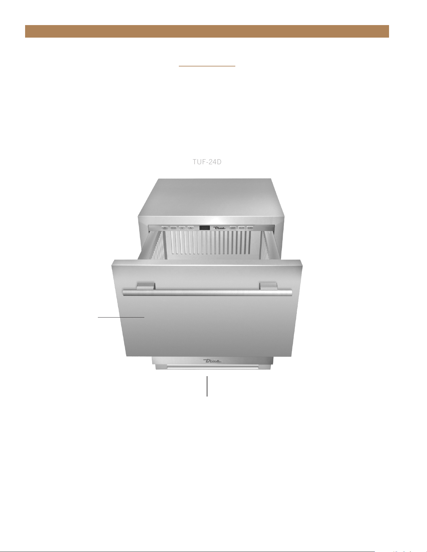
TRUE FREEZER DRAWERS
TUF-24D
EXCLUSIVE TRUE
®
-GLIDE
SOFT-CLOSE FEATURE
FOR BOTH DRAWERS
REMOVABLE KICK PLATE
FOR EASY CLEANING
24 INCH
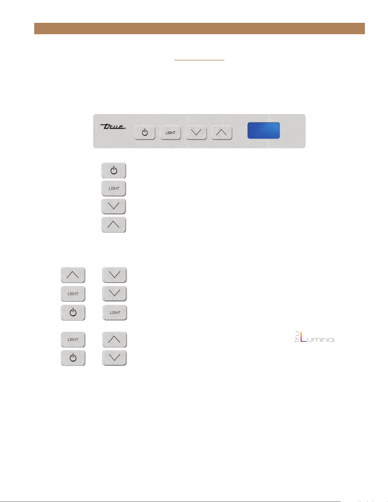
TEC_TM_156 | REV. G | EN 10/23/2023 Page 77 of 10015 & 24 INCH INSTALL GUIDE
APPLIANCE OPERATION
Control is located behind the user interface and can be accessed by removing 3 Phillips screws. This will also
give you access to the user interface, and LED driver. Control sequence is as follows:
USER INTERFACE COMMANDS
KEY COMBINATIONS
+
+
+
+
+
=
Lock / Unlock Keypad
=
Sabbath Mode
=
Showroom Mode – Shuts off all refrigeration components.
Displays set point. Lights are fully functional.
=
To switch color LEDs – 14 color TruLumina
®
patent.
=
To turn on door ajar alarm & high temperature alarm – Door ajar
alarm activates after 7 minutes.
• Refrigerator – High temperature alarm activates after one
consecutive hour at or above 50°F.
• Wine Cabinet – High temperature alarm activates after one
consecutive hour at or above 70°F.
=
Power, cuts power to all relays, resumes pulldown.
=
To turn on accent light.
=
Press to change set point down, hold to scroll down.
=
Press to change set point up, hold to scroll up.
15 INCH
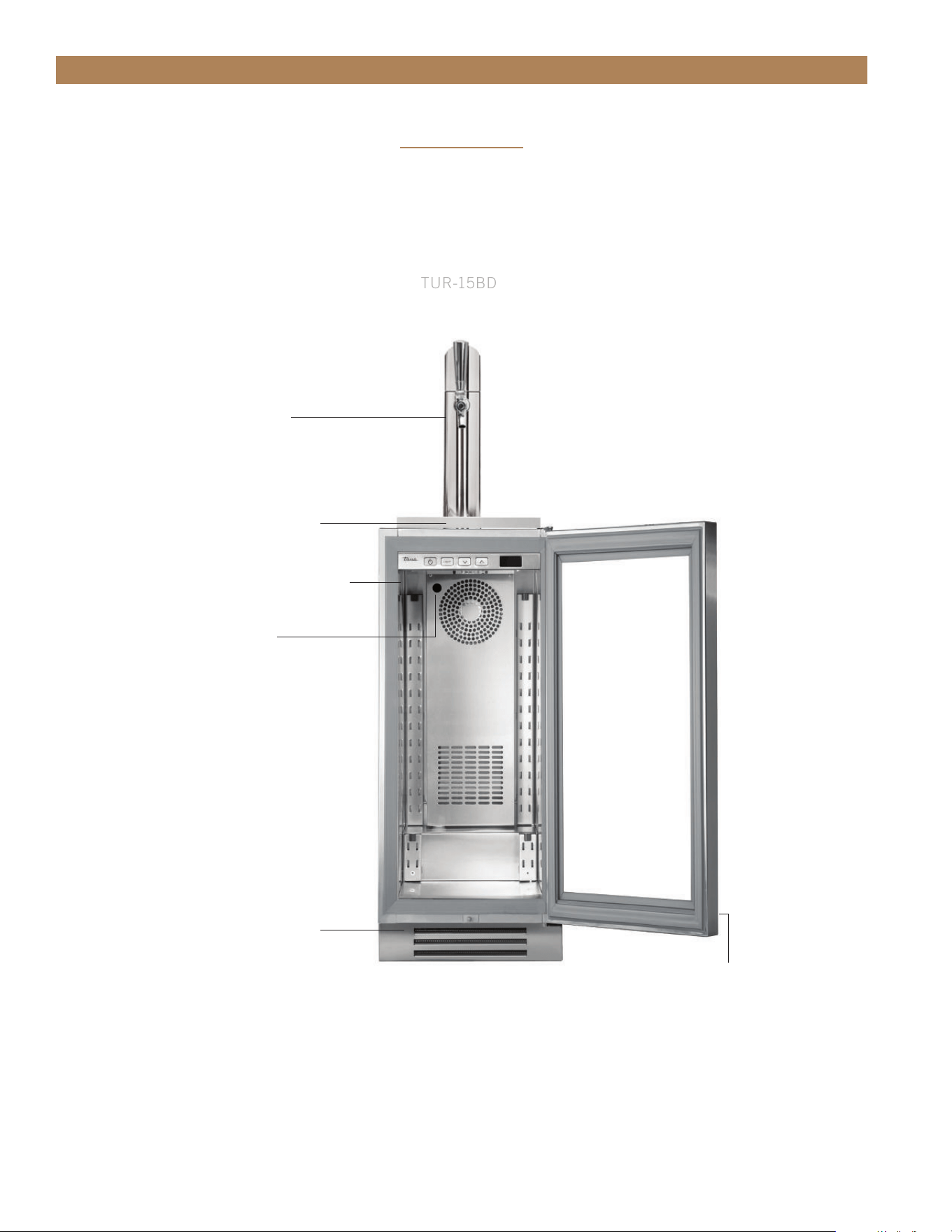
TRUE RESIDENTIAL
®
TEC_TM_156 | REV. G | EN10/23/2023Page 78 of 100
APPLIANCE OPERATION
TRUE BEVERAGE DISPENSER
TUR-15BD
LOCATION OF SERIAL TAG
CHILL HOSE
DRAFT TOWER
SPILL GRATE (TOP)
DRILL PAN (BOTTOM)
REMOVABLE KICK PLATE
FOR EASY CLEANING
DOOR LOCK
15 INCH
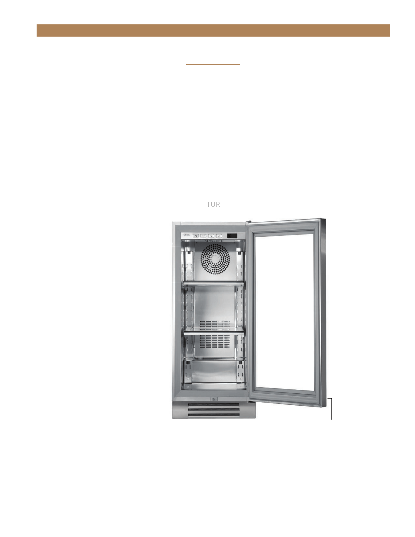
TEC_TM_156 | REV. G | EN 10/23/2023 Page 79 of 10015 & 24 INCH INSTALL GUIDE
APPLIANCE OPERATION
TRUE ALL REFRIGERATOR COMPONENTS
TUR
LOCATION OF SERIAL TAG
REMOVABLE KICK PLATE
FOR EASY CLEANING
ADJUSTABLE SPILL PROOF
GLASS SHELVES (2)
DOOR LOCK
15 INCH
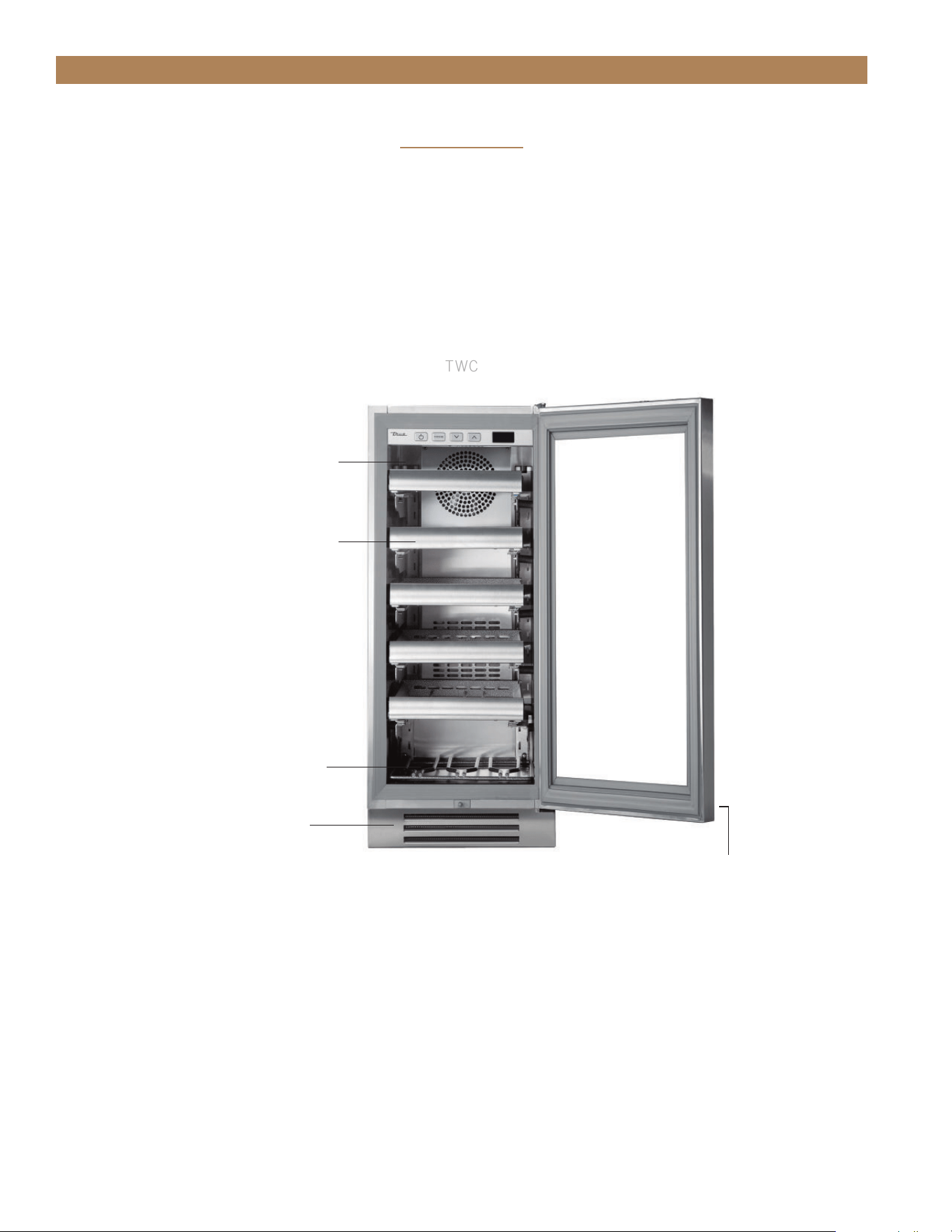
TRUE RESIDENTIAL
®
TEC_TM_156 | REV. G | EN10/23/2023Page 80 of 100
APPLIANCE OPERATION
TRUE WINE CABINET COMPONENTS
TWC
LOCATION OF SERIAL TAG
REMOVABLE KICK PLATE
FOR EASY CLEANING
ADJUSTABLE SLIDE OUT
WINE SHELVES (5)
FLOOR WINE CRADLE (1)
DOOR LOCK
15 INCH

TEC_TM_156 | REV. G | EN 10/23/2023 Page 81 of 10015 & 24 INCH INSTALL GUIDE
APPLIANCE OPERATION
HOME ALARM SYSTEM – DUAL ZONE WINE CABINET ONLY
Dual Zone wine units are provided with three wires located behind the kick-plate that may be connected to a
home alarm system. These connections are for low voltage, low current circuits similar to those used as signals
for alarms on doors and windows. Refer to the specifications of your alarm system to determine the type of
circuit used.
The color codes for the different circuits are as follows:
• Normally closed contacts: White with black and violet
• Normally open contacts: White with blue and black
• Common: White with black
CAUTION: ANY UNUSED TERMINALS SHOULD BE FULLY INSULATED AND ALL WIRES SHOULD BE
SECURED AWAY FROM MOVING PARTS AND SHARP EDGES.

TRUE RESIDENTIAL
®
TEC_TM_156 | REV. G | EN10/23/2023Page 82 of 100
NOTES

TEC_TM_156 | REV. G | EN 10/23/2023 Page 83 of 10015 & 24 INCH INSTALL GUIDE
GENERAL MAINTENANCE, CARE & CLEANING
PRESERVE THE MOMENT
®
CONDENSER COIL CLEANING
CONDENSATION
DRAWER REMOVAL, INSTALLATION & ADJUSTMENT
APPLIANCE CARE & CLEANING
TRUE RESIDENTIAL
®
TEC_TM_156 | REV. G | EN10/23/2023Page 84 of 100
GENERAL MAINTENANCE, CARE & CLEANING
CONDENSER COIL CLEANING
CAUTION – TAKE CARE DURING OPERATION, MAINTENANCE, OR REPAIRS TO AVOID CUTS OR
PINCHING FROM ANY APPPLIANCE PART/COMPONENT.
ATTENTION – LORS DE L’UTILISATION, DE L’ENTRETIEN OU DES RÉPARATIONS, IL FAUT
PRENDRE SOIN D’ÉVITER LES COUPURES ET LES PINCEMENTS POUVANT SURVENIR AU
CONTACT DES PIÈCES OU DES COMPOSANTES DE L’ARMOIRE.
Keeping the condenser coil clean minimizes required
servicing and lowers electrical cost. Warranty does not
cover cleaning the condenser coil.
WARNING – Electrical shock or burn
hazard. Unplug the unit or turn off the
power supply before proceeding. DO
NOT clean appliance with a pressure
washer or hose.
ATTENTION – Risque d’électrocution ou
de brûlure. Débranchez l’appareil ou
coupez l’alimentation électrique avant
de continuer. Ne nettoyez pas l’appareil
avec un nettoyeur haute pression ou un
tuyau.
CAUTION – Risk of eye injury from
debris. Eye protection is recommended.
ATTENTION – Les ailettes sont
coupantes. Soyez prudent pour éviter
les lésions oculaires. Une protection des
yeux est recommandée.
CAUTION – Coil fins are sharp. Gloves are
recommended.
ATTENTION – Les ailettes de la bobine
sont tranchantes. Les gants sont
recommandés.
REQUIRED TOOLS
Required tools include (but may not be limited to)
the following:
• Gloves
• Eye Protection
• Stiff Bristle Brush
• Vacuum Cleaner
• Flashlight
• Tank of Compressed Air
PROCEDURE
1. Remove the kickplate. See fig. 1.
2. With a stiff bristle brush, carefully clean
accumulated dirt from the front coil fins. See fig. 2.
3. With the dirt removed from the surface of the coil,
use a flashlight to verify you can see through the
coil and observe the condenser fan blade spinning.
See fig. 3.
4. If the view is clear, reinstall the kickplate, restore
power, and verify correct operation.
5. If the view is not clear, gently blow compressed air
or CO
2
through the coil until it is clean.
6. Carefully vacuum any dirt around the condensing
unit area.
7. Reinstall the kickplate, restore power, and verify
correct operation.
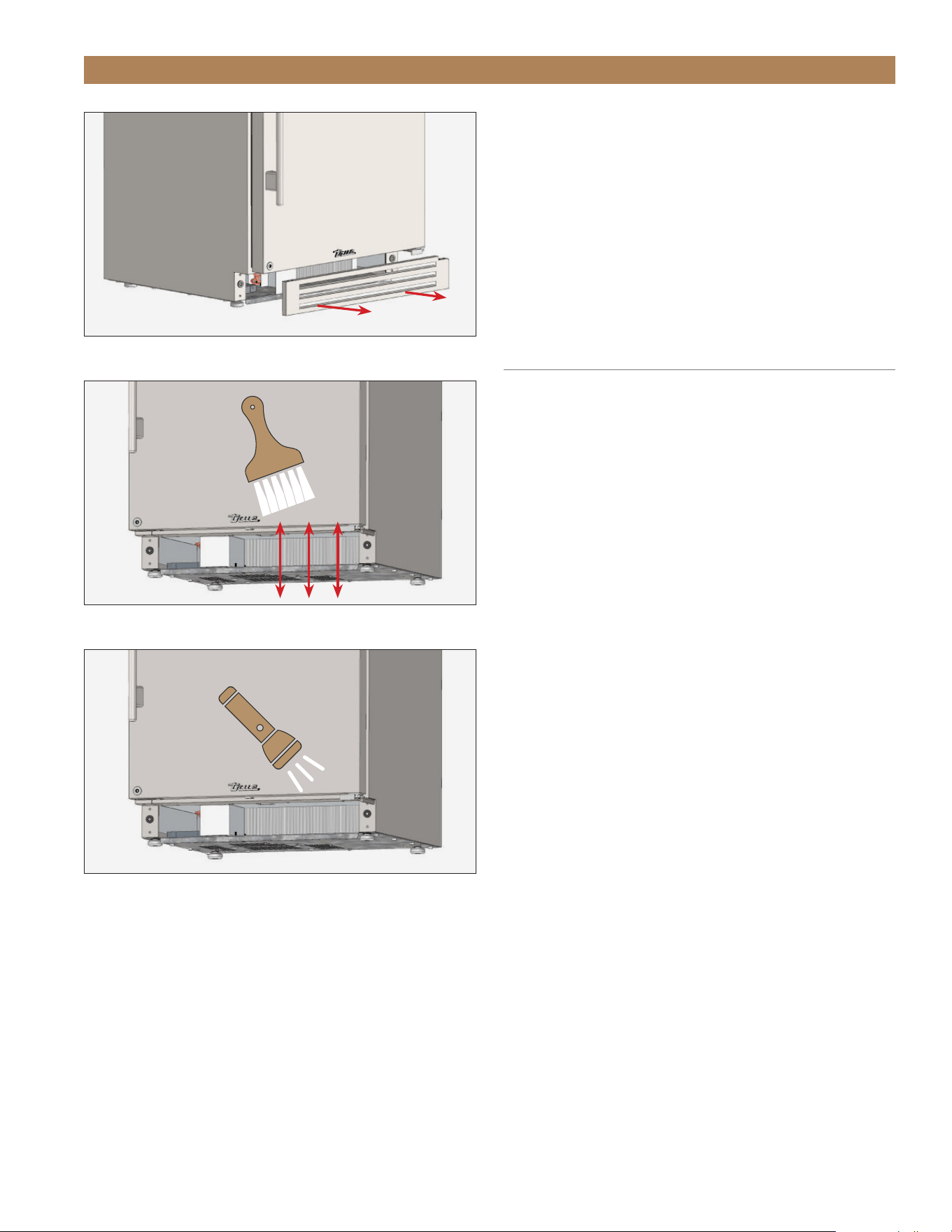
TEC_TM_156 | REV. G | EN 10/23/2023 Page 85 of 10015 & 24 INCH INSTALL GUIDE
GENERAL MAINTENANCE, CARE & CLEANING
ADDITIONAL INFORMATION
NOTE: THE CLEANING OF THE CONDENSER IS
NOT COVERED BY WARRANTY!
If you have any questions, please contact your local
TRUE Manufacturing Service Department. See contact
information on page 8 or 92.
• Do not place any filter material in front of the
condensing coil.
CONDENSATION
Excessive condensation can be caused by leaving the
door/drawer open for long periods of time or running
the appliance with little to no product inside.
FIG. 1.
Pull the kickplate off the magnets.
FIG. 2.
Never brush across coil fins.
FIG. 3.
Verify all blockages have been removed.
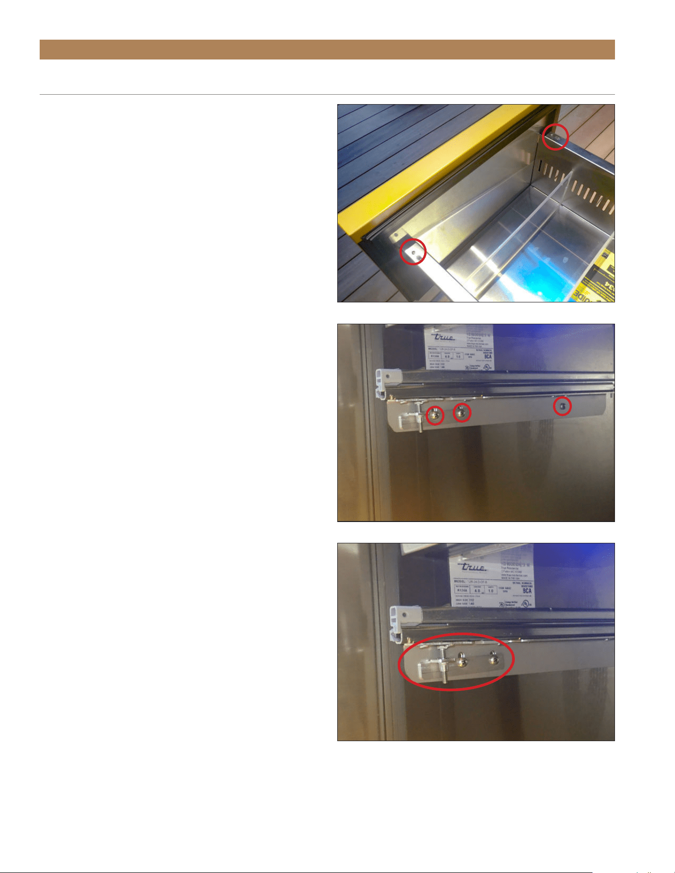
TRUE RESIDENTIAL
®
TEC_TM_156 | REV. G | EN10/23/2023Page 86 of 100
GENERAL MAINTENANCE, CARE & CLEANING
DRAWER REMOVAL, INSTALLATION & ADJUSTMENT
REQUIRED TOOLS
Required tools include (but may not be limited to)
the following:
• Phillips Scrrewdriver
REMOVAL
1. Open the drawer.
2. Remove the drawer screws. See fig. 1.
3. Lift the drawer from the slides.
4. Remove the slide adjustment bracket and drawer
slide assembly. See fig. 2.
5. Repeat step 4 on the opposite side.
INSTALLATION
1. Install the slide assembly and the adjustment
bracket. See fig. 3.
NOTE: DO NOT FULLY TIGHTEN THE ADJUSTMENT
BRACKET SCREWS.
2. Repeat step 1 on the opposite side.
3. Extend the drawer slides. See fig. 4.
4. Position the drawer. Then, install the drawer
screws.
NOTE: BE SURE THE DRAWER LOCKS INTO
PLACE.
5. Verify the drawer alignment. Adjust drawer
alignment as needed. See “Adjustment” (pg. 85).
6. Tighten the alignment bracket screws.
FIG. 1.
Drawer screw locations
FIG. 2.
Drawer slide and adjustment bracket screw locations.
FIG. 3.
Extend the drawer slides.
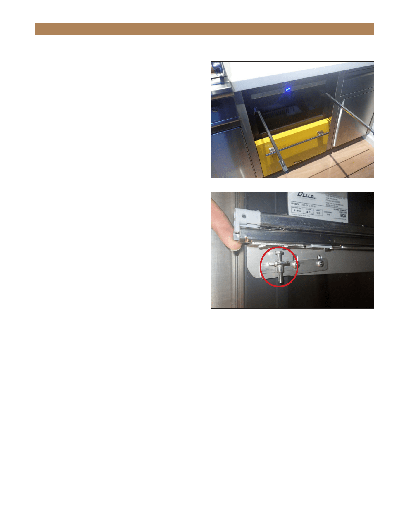
TEC_TM_156 | REV. G | EN 10/23/2023 Page 87 of 10015 & 24 INCH INSTALL GUIDE
GENERAL MAINTENANCE, CARE & CLEANING
DRAWER REMOVAL, INSTALLATION & ADJUSTMENT (CONT.)
ADJUSTMENT
1. Open the drawer.
2. With the adjustment bracket screws loosened, lift
the drawer slide and the side of the drawer. Then,
lower or raise the adjustment screw. See fig. 5.
NOTE: DO NOT LIFT THE DRAWER BY THE
HANDLE.
3. Close the drawer and verify the alignment.
4. Repeat steps 1-3 as needed.
5. Tighten the alignment bracket screws.
NOTE: DO NOT LIFT THE DRAWER BY THE
HANDLE.
FIG. 5.
Drawer adjustment screw location. Left side shown.
Drawer removed for illustration purposes.
FIG. 4.
Adjustment bracket orientation. Left side shown.

TRUE RESIDENTIAL
®
TEC_TM_156 | REV. G | EN10/23/2023Page 88 of 100
GENERAL MAINTENANCE, CARE & CLEANING
CAUTION: DO NOT USE ANY STEEL
WOOL, ABRASIVE OR CHLORINE
BASED PRODUCTS TO CLEAN
STAINLESS STEEL SURFACES.
STAINLESS STEEL OPPONENTS
There are three basic things which can break down
your stainless steel’s passivity layer and allow corrosion
to form.
• Scratches from wire brushes, scrapers, and steel
pads are just a few examples of items that can be
abrasive to stainless steel’s surface.
• Deposits left on your stainless steel can leave spots.
You may have hard or soft water depending on what
part of the country you live in. Hard water can leave
spots. Hard water that is heated can leave deposits
if left to sit too long. These deposits can cause the
passive layer to break down and rust your stainless
steel. All deposits left from food prep or service
should be removed as soon as possible.
• Chlorides are present in table salt, food, and water.
Household and industrial cleaners are the worst
type of chlorides to use.
STAINLESS STEEL CLEANING AND
RESTORATION
Stainless steel cleaners must be free of phosphates,
chlorine, chloride, and ammonia.
TRUE offers environmentally-friendly cleaner and
polish through our True Store at https://store.
trueresidential.com/products/stainless-steel-clean-
polish-kit
CUSTOM PAINTED APPLIANCES AND
HARDWARE
For painted doors and other surfaces, use a mild
solution of soap and water with a soft microfiber cloth.
APPLIANCE CARE & CLEANING

TEC_TM_156 | REV. G | EN 10/23/2023 Page 89 of 10015 & 24 INCH INSTALL GUIDE
GENERAL MAINTENANCE, CARE & CLEANING
8 TIPS TO HELP PREVENT RUST ON STAINLESS STEEL
• Maintain the Cleanliness of Your Equipment – Avoid
build-up of hard stains by cleaning frequently. Use
cleaners at the recommended strength (alkaline
chlorinated or non-chloride).
• Use the Correct Cleaning Tools – Use non-abrasive
tools when cleaning your stainless steel products.
The stainless steel’s passive layer will not be
harmed by soft cloths and plastic scouring pads.
• Clean Along Polishing Lines – Polishing lines ("grain")
are visible on some stainless steels. Always scrub
parallel to polishing lines when visible. Use a plastic
scouring pad or soft cloth when you cannot see the
grain.
• Use Alkaline, Alkaline-Chlorinated or Non-Chloride
Cleaners – While many traditional cleaners are
loaded with chlorides, the industry is providing an
ever increasing choice of non-chloride cleaners. If
you are not sure of your cleaner’s chloride content,
contact your cleaner supplier. If they tell you that
your present cleaner contains chlorides, ask if
they have an alternative. Avoid cleaners containing
quaternary salts, as they can attack stainless steel,
causing pitting and rusting.
• Rinse – When using chlorinated cleaners, you must
rinse and wipe dry immediately. It is better to wipe
standing cleaning agents and water as soon as
possible. Allow the stainless steel equipment to air
dry. Oxygen helps maintain the passivity film on
stainless steel.
• Never Use Hydrochloric Acid (Muriatic Acid) on
Stainless Steel – Even diluted, hydrochloric acid
can cause corrosion, pitting and stress corrosion
cracking of stainless steel.
• Water Treatment – To reduce deposits, soften hard
water when possible. Installation of certain filters
can remove corrosive and distasteful elements.
Salts in a properly maintained water softener can
also be to your advantage. Contact a treatment
specialist if you are not sure of the proper water
treatment.
• Regularly Restore & Passivate Stainless Steel –
Stainless steel gets its stainless properties from
the protective chromium oxides on its surface.
If these oxides are removed by scouring, or by
reaction with harmful chemicals, then the iron in
the steel is exposed and can begin to oxidize, or
rust. Passivation is a chemical process that removes
free iron and other contaminants from the surface
of stainless steel, allowing the protective chromium
oxides to re-form.
APPLIANCE CARE & CLEANING

TRUE RESIDENTIAL
®
TEC_TM_156 | REV. G | EN10/23/2023Page 90 of 100
NOTES

TEC_TM_156 | REV. G | EN 10/23/2023 Page 91 of 10015 & 24 INCH INSTALL GUIDE
SERVICING & REPLACING COMPONENTS
HANDLE TIGHTENING
CONTACT INFORMATION
SERIAL LABEL LOCATION
FREQUENTLY ASKED QUESTIONS
WARRANTY
PRESERVE THE MOMENT
®
SERVICING & ADJUSTMENTS
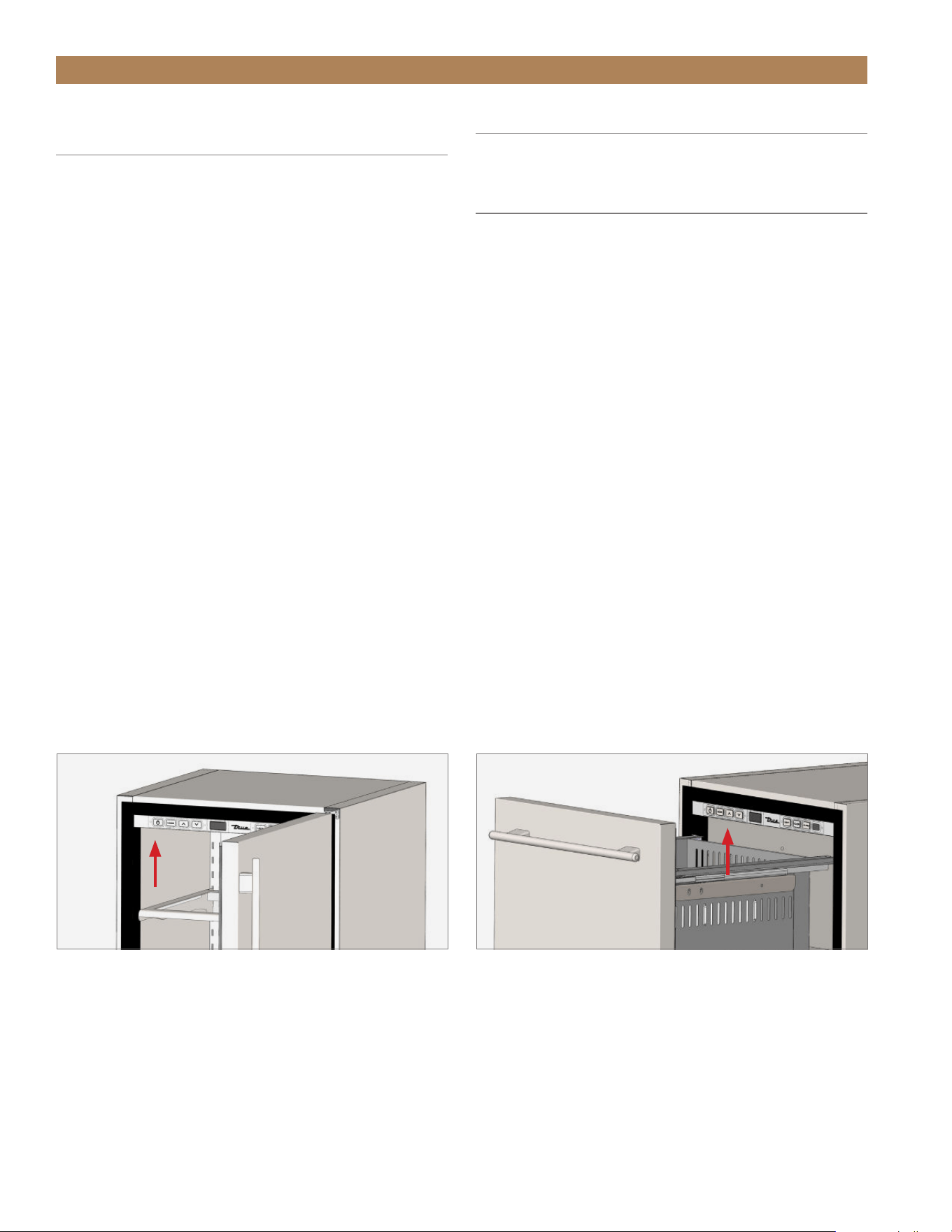
TRUE RESIDENTIAL
®
TEC_TM_156 | REV. G | EN10/23/2023Page 92 of 100
SERVICING & ADJUSTMENTS
HANDLE TIGHTENING
Tighten the handle with a 3/32” Allen wrench.
CONTACT INFORMATION
For any questions about installation, please contact
your TRUE dealer or TRUE Residential Technical
Service. Please have your model and serial number
(see serial label location below) available so we can
better assist you with your service- or parts-related
inquiries.
CUSTOMER SERVICE
Phone: 888-616-8783
info@true-residential.com
WARRANTY DEPARTMENT
Phone: 844-849-6179
TrueResidentialWarranty@truemfg.com
TECHNICAL SERVICE DEPARTMENT
Phone: 844-746-9423
TrueResidentialService@truemfg.com
SERIAL LABEL LOCATION
Your serial label contains important information such as your model name and serial number. The label is located
on the upper left interior wall.
SERVICING & REPLACING
COMPONENTS
NOTE: ANY APPLIANCE ADJUSTMENTS ARE TO
BE MADE AFTER THE APPLIANCE HAS BEEN
VERIFIED LEVEL AND PROPERLY SUPPORTED.
• Replace component parts with original equipment
manufacturer (OEM) components.
• Contact the dealer or our parts department at
844-849-6179 or TrueResidentialPart[email protected]
for replacement parts.
• Have a licensed service provider service your unit
to minimize the risk of possible ignition due to
incorrect parts or improper service and to ensure
the operator’s health and safety.
• Unplug the refrigerator/freezer before cleaning or
making any repairs. Powering off an electronic
control may not remove power from all components
(e.g., light circuits, perimeter heaters, and
evaporator fans).
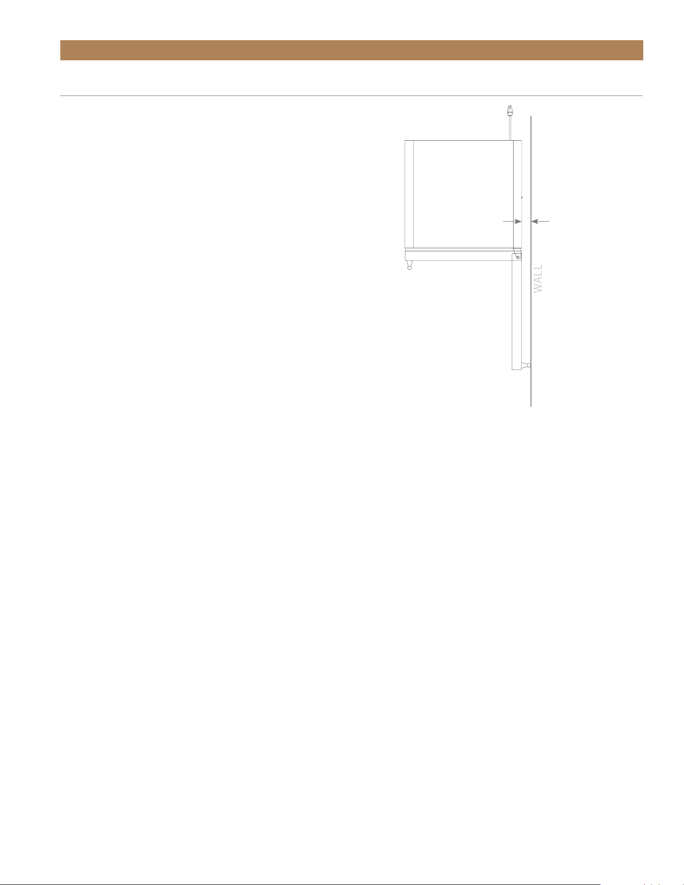
TEC_TM_156 | REV. G | EN 10/23/2023 Page 93 of 10015 & 24 INCH INSTALL GUIDE
SERVICING & ADJUSTMENTS
Q. How do I adjust the temperature?
A. Refer to True Precision Control
®
Operation listed
in Table of Contents on pg.64.
Q. Why does the evaporator fan motor run constantly?
A. This is a normal operation in wine units. The
evaporator fan motor will run continuously to ensure
even temperature throughout your appliance. This will
only stop when the door is opened to keep warm air
from being circulated throughout the appliance.
Q. Why isn’t my unit cooling properly?
A. Check to see that there are no obstructions to the
condenser coil (behind front grill). Confirm that the
condenser area is clean.
Q. How do I adjust or remove a shelf from my current
configuration?
A. Refer to Glass Shelf Adjustment listed in Table of
Contents on pg.52.
Q. Why is there warm air coming from the bottom/
front of the refrigerator (grill/kickplate area)?
A. This is normal as heat dissipation is part of the
refrigeration cycle.
Q. Why is there condensation forming on the inside
or outside of the unit?
A. Leaving the door open for a long period of time or a
unit that is running with little to no product inside may
also cause excessive condensation.
Q. What are the preset limits for the high
temperature alarm?
A. The electronic control will monitor temperatures and
activate an alert if unsafe product temperatures are
present for more than 60 minutes. For single and dual
zone wine cabinets, the alarm will activate at 70°F. For
all refrigerators, the alarm will activate at 50°F.
Q. How much distance is needed from the wall to
have the hinge on the wall side and still open 90
degrees?
A. 2 inches.
Q. Can I put 2 units flush against each other
without spacing?
A. When installing two or more True units side-by-
side, TRUE recommends installing one (1) foam
pad between the appliances (on either appliance) to
prevent moisture from developing.
To order foam pads, contact our parts department at
844-849-6226 or TrueResidentialParts@TrueMfg.com.
Q. Does True sell the wood doors on overlay?
A. No, for wood front doors, reach out to your cabinet
maker and provide them with the overlay template
available on the right hand side of our document
library: http://www.true-residential.com/Support/
Document-Library/
Q. Does the overlay come with the handle?
A. No, our handle can be ordered as an accessory,
or any pull can be added to your overlay drawer.
1
7/8
"
WALL
FREQUENTLY ASKED QUESTIONS

TRUE RESIDENTIAL
®
TEC_TM_156 | REV. G | EN10/23/2023Page 94 of 100
SERVICING & ADJUSTMENTS
FREQUENTLY ASKED QUESTIONS (CONT.)
Q. Do True units have a zero clearance hinge?
A. Yes. No spacing is needed on the either side of our
unit. It can be placed flush with adjoining cabinetry
and still open to 90°.
Q. Why doesn’t the warranty cover commercial units
in my home?
A. Due to Department of Energy regulations on
refrigerator energy use, we are not able to market
and sell our commercial units in homes. Providing
a warranty to home users is included in this.
Q. What is the Decibel rating of the units?
A. 42-47 db.
Q. How do I change the lighting?
A. For models that include a color button, simply push
the button until the desired color appears.
For 15 inch models without a color button press
+ at the same time until your desired
color is reached.
On 24 inch dual zone models press + .
Q. My display was reading “REF” What does that
mean?
A. The REF code is shown when the appliance doesn’t
reach the desired set temp in the allotted time. The
problem may be that the door was left open or very hot
product was loaded into the unit. To reset the code,
simply power off, and power on the refrigerator. If the
code returns, please contact True for service.
Q. I don’t see a service company in my area, who can
I call?
A. Please call True’s service line: 888.616.8783 or
email us: info@true-residential.com to have us help find
an appropriate servicer for your appliance.
Q. Does my refrigerator have to be covered outdoors?
A. No. All True undercounter are UL rated for
outdoor use.
True units are able to be installed free standing. If left
exposed to the elements throughout winter months,
a cover will help preserve the life and beauty of your
True product.
PLEASE NOTE: THE GASKETS DO NOT
PROVIDE A WATER TIGHT SEAL, SO IT IS
RECOMMENDED THAT THE UNIT IS INSTALLED
SO THAT THE COUNTERTOP OF YOUR
OUTDOOR KITCHEN COVERS THE DOOR OR
DRAWER GASKET.
Q. What should I do in the winter? Do I have to bring
it in? How cold can it get before it’s a problem?
A. In regions with cold winters (consistently below
32ºF), True refrigerators should be turned to off, and
emptied of all contents. If exposed to the elements,
covering your cooler will extend its life and beauty.
BEVERAGE DISPENSER QUESTIONS
Q. What type of tap system can be used with a
True unit?
A. Different tap systems can be used on 1/4 barrel
short kegs, but low profile taps are not available in the
non-sankey variety, and therefore will probably not fit
in our dispensers when used with tall kegs.
Q. Where can I get my CO
2
tank filled?
A. C0
2
is available at many sporting good stores as
well as paintball stores. C0
2
canisters can often be
exchanged (much like propane tanks) at many liquor
stores as well as nationally at AIRGAS locations.
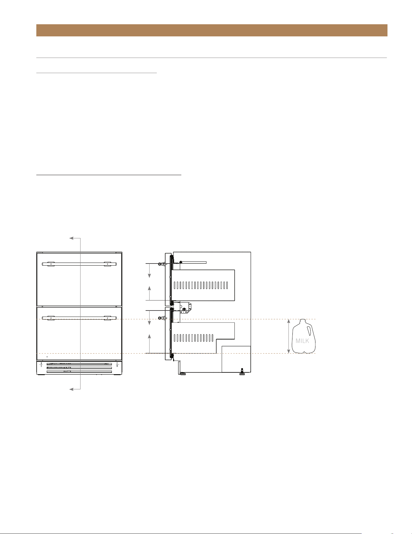
TEC_TM_156 | REV. G | EN 10/23/2023 Page 95 of 10015 & 24 INCH INSTALL GUIDE
SERVICING & ADJUSTMENTS
FREQUENTLY ASKED QUESTIONS (CONT.)
WINE CABINET QUESTIONS
Q. Can I store Magnum bottles?
A. Magnums will fit on our floor rack which holds
5 bottles. Also, our shelves are removable to create
additional space.
Q. Can I store pinot/Bordeaux/Riesling bottles?
A. Yes. Almost all bottle varieties will fit in your
True Wine Cabinet.
DRAWER APPLIANCE QUESTIONS
Q. How tall are the drawers? Can I store an upright
bottle of wine, or a gallon of milk?
A. In refrigerator drawers, yes. Please see the
drawing below.
10-9/32"
11-25/32"
A
A
Scale 1 : 8
10
"
MILK
REFRIGERATOR DRAWER

TRUE RESIDENTIAL
®
TEC_TM_156 | REV. G | EN10/23/2023Page 96 of 100
TRUE RESIDENTIAL
®
SERIES LIMITED WARRANTY STATEMENT
LIMITED 30 DAY COSMETIC WARRANTY
Stainless steel doors, handles, and shelves are warranted to be free from defective materials or workmanship for a period of th
irty (30) days from the date of
original retail purchase. Any defects must be reported to the selling dealer within thirty (30) days from the date of original
retail purchase. This limited warranty
excludes any type of freight / concealed damage.
THREE-YEAR PARTS & LABOR WARRANTY *FOR UNITS PURCHASED AFTER FEB 1, 2013
TRUE
®
warrants to the original purchaser of every new TRUE refrigerated unit, the cabinet and all parts thereof, to be free from def
ects in material or workmanship
under normal and proper use and maintenance as specified by TRUE and upon proper installation and start-up in accordance with th
e instruction packet supplied
with each TRUE unit. TRUE’s obligation under this warranty is limited to a period of three (3) years from the date of original installation or thirty nine (39) months
after shipment date from TRUE, whichever occurs first. Contact TRUE Warranty regarding warranty for installations in a commercial/light commercial application.
SIX-YEAR SEALED SYSTEM WARRANTY – PARTS & LABOR *FOR UNITS PURCHASED AFTER FEB 1, 2013
TRUE warrants its hermetically sealed system: compressor, evaporator coil, condenser coil, drier, metering device and connecting tubing to be free from defects
in both material and workmanship under normal and proper use and maintenance service for a period of six (6) years from the dat
e of original installation but
not to exceed six (6) years and three (3) months after shipment from the manufacturer, whichever occurs first.
SEVEN THROUGH TWELVE-YEAR SEALED SYSTEM WARRANTY – PARTS ONLY
For units shipped from TRUE after Feb 1, 2017 and REGISTERED via TRUE’s Product Registration Page – TRUE warrants its hermetically sealed system:
compressor, evaporator coil, condenser coil, drier, metering device and connecting tubing to be free from defects in both material and workmanship under normal
and proper use and maintenance service period of Twelve (12) years from the date of original installation but not to exceed twelve (12) years and three (3) months
after shipment from the manufacturer, whichever occurs first. Product must be registered with TRUE within 12 months of the unit’s installation to qualify for this
warranty. Factory seconds, ADA models, and clear Ice machines are excluded from this warranty.
DISPLAY PRODUCTS
TRUE Residential Products on showroom display that are sold more than 3 years (36 months) from the invoice date to the dealer
would carry a 1 year parts and
labor warranty, along with an additional 4 year sealed system, parts only warranty.
TERMS APPLICABLE TO EACH WARRANTY
Any part covered under the above warranties that is determined by TRUE to have been defective within the time frame is limited
to the repair or replacement,
including labor charges, of defective parts or assemblies. The labor warranty shall include standard straight time labor char
ges only and reasonable travel time,
as determined by TRUE. Units must be purchased through an authorized TRUE Residential dealer in order to qualify for warranty.
WARRANTY CLAIMS
All claims for labor or parts must be made directly through TRUE. All claims should include: model number and serial number of cabinet, proof
of purchase, and date of installation. In case of warranted compressor, the compressor model tag must be returned to TRUE along with the above
listed information.
WHAT IS NOT COVERED BY THIS WARRANTY
This limited warranty does not cover any damage due to: (a) transportation; (b) storage; (c) installation; (d) improper use; (
e) failure to follow the product
instructions or to perform any preventive maintenance; (f) modifications or alterations; (g) neglect; (h) unauthorized repair; (
i) normal wear and tear; or (j) external
causes such as accidents, abuse, act of God, or other actions or events beyond our reasonable control.
NO CONSEQUENTIAL DAMAGES
TRUE is not responsible for economic loss, profit loss; or special, indirect or consequential damages, including without limitat
ion, losses or damages arising from
food or product spoilage claims whether or not on account of refrigeration failure.
WARRANTY IS NOT TRANSFERABLE
This warranty is not assignable and applies only in favor of the original purchaser/user to whom delivered. Any such assignment
or transfer shall void the
warranties herein made and shall void all warranties, express or implied, including any warranty or merchantability or fitness for a particular purpose.
IMPROPER ELECTRICAL CONNECTIONS
TRUE is not responsible for the repair or replacement of failed or damaged components resulting from electrical power failure,
high or low voltage, use of
extension cords, or improper grounding of the unit.
REMEDY LIMITATIONS
TRUE’s sole obligation under this warranty is limited to either repair or replacement of parts. This warranty neither assumes nor authorizes any person to assume
obligations other than those expressly covered by this warranty.The remedies described in this warranty statement are the sole and exclusive remedies and TRUE’s
entire liability for any breach of this limited warranty. TRUE’s liability shall under no circumstances exceed the actual amount paid for the defective product, nor
shall TRUE under any circumstances be liable for any consequential, incidental, special or punitive damages or losses, whether direct or indirect.
LIMIT ON IMPLIED WARRANTIES
TRUE limits the duration and remedies of all implied warranties, including without limitation the warranties of merchantability
and fitness for a particular purpose
to the duration of this express limited warranty statement.
YOUR RIGHTS UNDER STATE LAW
This warranty gives you specific legal rights and you may have other rights that vary from state to state. Some states do not al
low the exclusion or limitation of
consequential damages or a limitation on how long an implied warranty lasts, so the above exclusion or limitation may not apply to you.
ENVIRONMENTAL ATTRIBUTES
Any and all environmental attributes, including environmental offset credit rights, with respect to TRUE refrigeration units m
anufactured after September 1,
2015, shall remain the property of TRUE Manufacturing Co., Inc. and are not transferred.
OUTSIDE U.S./CANADA
This warranty does not apply to, and TRUE is not responsible for, any warranty claims made on products sold or used outside the United States or Canada.
SUBMIT WARRANTY CLAIMS TO: True Residential
2001 East Terra Lane
O’Fallon, MO 63366 TrueResidentialClaims@TrueMfg.com
DF_210682_04.23

TEC_TM_156 | REV. G | EN 10/23/2023 Page 97 of 10015 & 24 INCH INSTALL GUIDE
NOTES

TRUE RESIDENTIAL
®
TEC_TM_156 | REV. G | EN10/23/2023Page 98 of 100
NOTES

TEC_TM_156 | REV. G | EN 10/23/2023 Page 99 of 10015 & 24 INCH INSTALL GUIDE
NOTES

TRUE RESIDENTIAL
®
10/23/2023Page 100 of 100
BC_219031_9.23
838155-G
CONTACT US
true-residential.com
636.240.2400
|
toll free 888.616.8783
PRESERVE THE MOMENT
®