EN
Please read the Important Information for the User in the product
box for product warnings and other important safety information.
Pedaling Monitor Sensor
SGY-PM910H
Installation Manual (for dealers)

2
EN
Introduction
Table of Contents
Introduction
Features ....................................................................3
Manuals ...........................................................................3
Compatibility ..............................................................4
Getting Ready
Product Conguration ................................................5
Accessories ......................................................................5
Before Starting Installation ........................................6
Installation Procedure ......................................................6
Eliminating Static Electricity during Installation ................6
Checking Operation of the Sensors ..........................7
Installing the Magnets................................................9
Checking the Position of the Magnets and Magnetic
Sensors ............................................................................9
Selecting the Type of Magnets .........................................9
Installing Patch Type Magnets .......................................11
Installing Arm Type Magnets ..........................................13
Calibrating the Magnets and Fixing Them in Place
.................................................................................15
Pairing and Calibrating
Before Pairing and Calibrating ................................18
Pairing and Calibrating Procedure .................................18
Placing the Bicycle in a Secure Work Position ..............18
Pairing the Pedaling Monitor Sensor .......................19
Specifying the Device Number to Pair it ........................21
Checking Device Numbers ............................................22
Calibrating the Zero Point ..............................................23
Calibration ...............................................................23
Checking the Calibration .........................................24
Troubleshooting
Troubleshooting .......................................................25
Error codes ....................................................................31
Assembling the Chainring and Installing the Right
Transmitter ..............................................................32
Specications and Support
Care, Maintenance, and Storage ............................34
Specications ..........................................................35
Introduction

3
EN
Introduction
Features
This product is a sensor system that analyzes the pedaling of a bicycle in real time. It calculates the direction and
intensity of the force acting on the pedals and calculates pedaling efciency.
Description of components
Strain gauge unit:• Detects the strain on the crank and calculates the direction and intensity of the force on the crank.
Magnet:• Used to detect the angle of rotation.
Transmitters:• Send information from the strain gauge unit and the magnet to the Cyclocomputer.
Switching modes
The push switch in the right transmitter changes the system to the following modes.
Pedaling monitor mode:•
Used in combination with the Cyclocomputer SGX-CA500/CA900.
This mode calculates pedaling efciency and maximizes the functionality of the product.
In this User’s Manual, the case when it is used with SGX-CA500 is described as example.
Power meter mode:•
Used with a Cyclocomputer that supports ANT+™.
This product is ANT+ certied.
Visit http://www.thisisant.com/directory/ for a list of compatible products and apps.
Manuals
The product’s manuals consist of this User’s Manual and an Installation Manual.
User’s Manual:•
Explains how to pair the product with the Cyclocomputer and calibrate the sensors.
Installation Manual (for dealers):•
[For American Users] http://www.pioneerelectronics.com
[For Canadian Users] http://www.pioneerelectronics.ca
[For European Users] http://www.pioneer.eu
Explains details about handling methods. The product installation methods (for dealers) are also described as references.
Important Information for the User:•
Important Information for the User provides detailed information related to safety.
4
EN
Introduction
Compatibility
Crank sets
The product is compatible with the following crank sets.
Crank sets Remarks
SHIMANO FC-9000 Crank lengths of 165 mm, 167.5 mm, 170 mm, 172.5 mm, 175 mm, crank set of 50-34T, 52-•
36T, 52-38T, 53-39T, 54-42T, 55-42T are compatible. *
SHIMANO FC-6800 Crank lengths of 165, 170, 172.5, 175 mm, crank set of 50-34T, 52-36T, 53-39T are •
compatible. *
* Descriptions in this manual are for a 170 mm crank set.
This product is designed to be used for recreational cycling and cycle training applications only and is not designed to withstand
racing conditions.
Additionally, this product is designed to be used while cycling on paved roads only. Any damage or malfunction arising from
use in racing or riding on dirt roads, cobblestone or any other unpaved roads will not be covered by the manufacturer’s limited
warranty.
Installing, pairing, and calibrating the product requires specialized techniques and tools. Ask the shop where you
bought the product to install, pair, and calibrate it.
5
EN
Getting Ready
Getting Ready
Product Conguration
Accessories
This product contains the following parts.
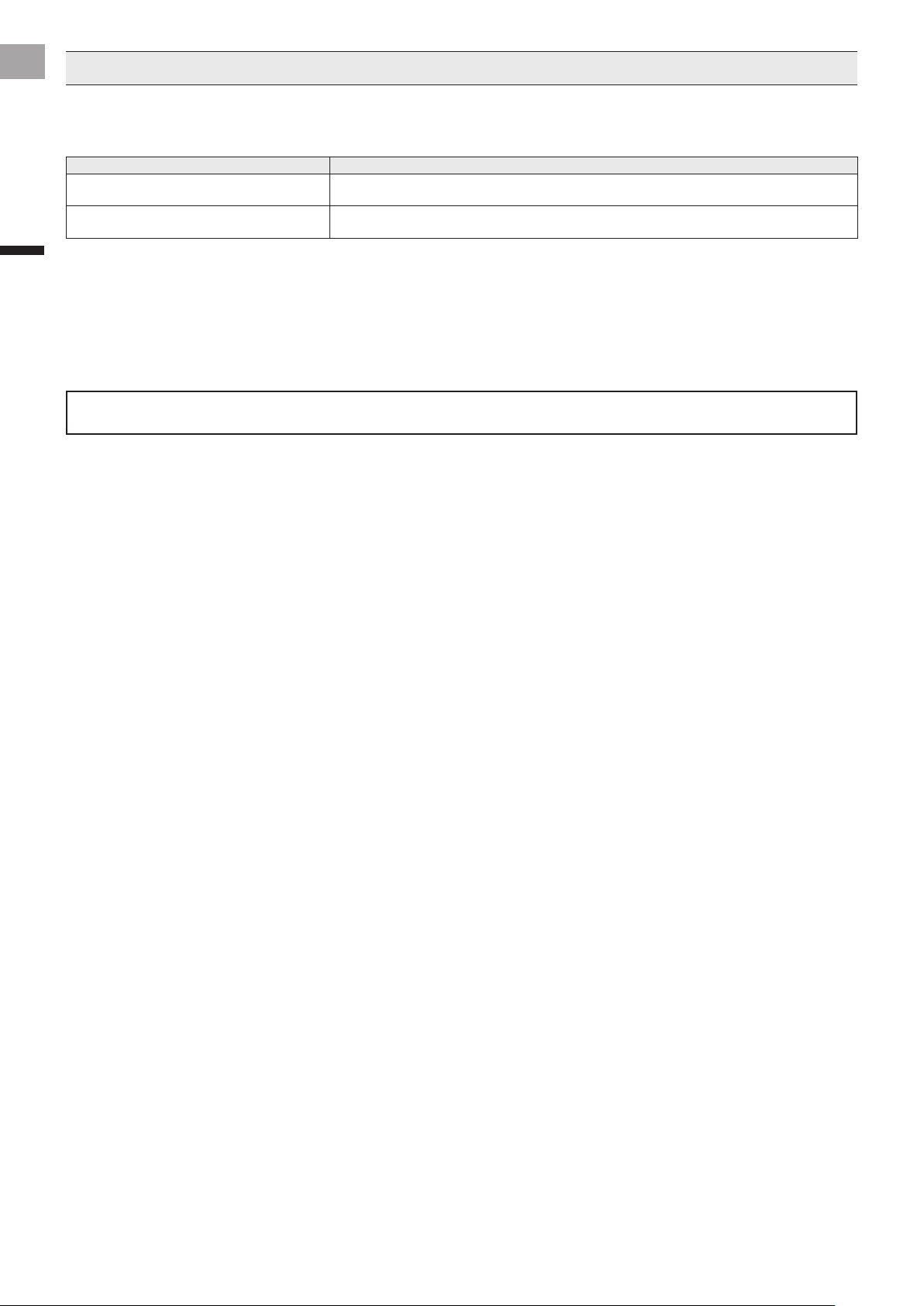
Pedaling monitor sensor (right side)
Right transmitter
Junction cable
Strain gauge unit
Junction box
Pedaling monitor sensor part (right side)
For FC-9000
For FC-6800
Chain ring adapter
Strain gauge unit cover x 1 for each type
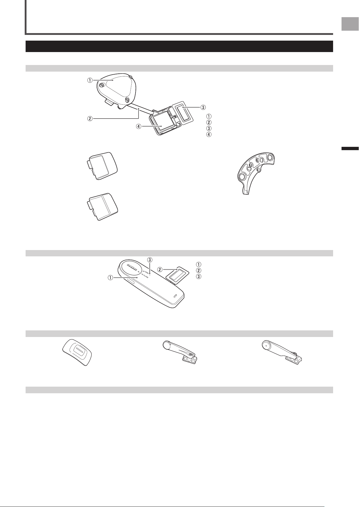
Pedaling monitor sensor (left side)
Left transmitter
Strain gauge unit
LED
Pedaling monitor sensor part (left side)
Magnet
Patch type x 2 Arm type (right side) Arm type (left side)
Others
User’s Manual (this document)•
Warranty Card•
Important Information for the User•
Batteries (CR2032) x 2•
(pre-installed in the left and right sensors)
Right transmitter cover (metallic gray)•
Hex screws (M2.6 x 8mm) x 3•
(for the right transmitter x 3)
Hex screws (M2.6 x 5mm) x 3•
(spare for the right transmitter cover x 3)
Cable ties x 10•
(for the left magnet x 2, for the right magnet
x 2, spare x 6)
Cushions for the arm type magnet installation x 2•

6
EN
Getting Ready
Before Starting Installation
Installing, pairing, and calibrating the product requires specialized techniques and tools. Ask the shop where you
bought the product to install, pair, and calibrate it.
Installation Procedure
The product is installed in the order shown here.
1. Checking operation of the sensors (page 7)
2. Installing the magnet rings (page 9)
3. Calibrating the magnets and xing them in place (page 15)
Eliminating Static Electricity during Installation
Before starting the installation, touch a large metal object (such as a door knob or metal table) to discharge any static electric
charge in your body.
Eliminate static electric charge occasionally while installing the product.
7
EN
Getting Ready
Before installing the sensors, conrm that they operate correctly.
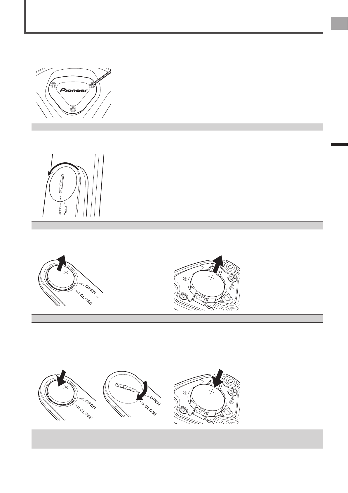
1
Remove the right transmitter’s cover.
Use a hex wrench (2 mm) to loosen the screw and remove the cover.
Be careful not to lose the removed screw.•
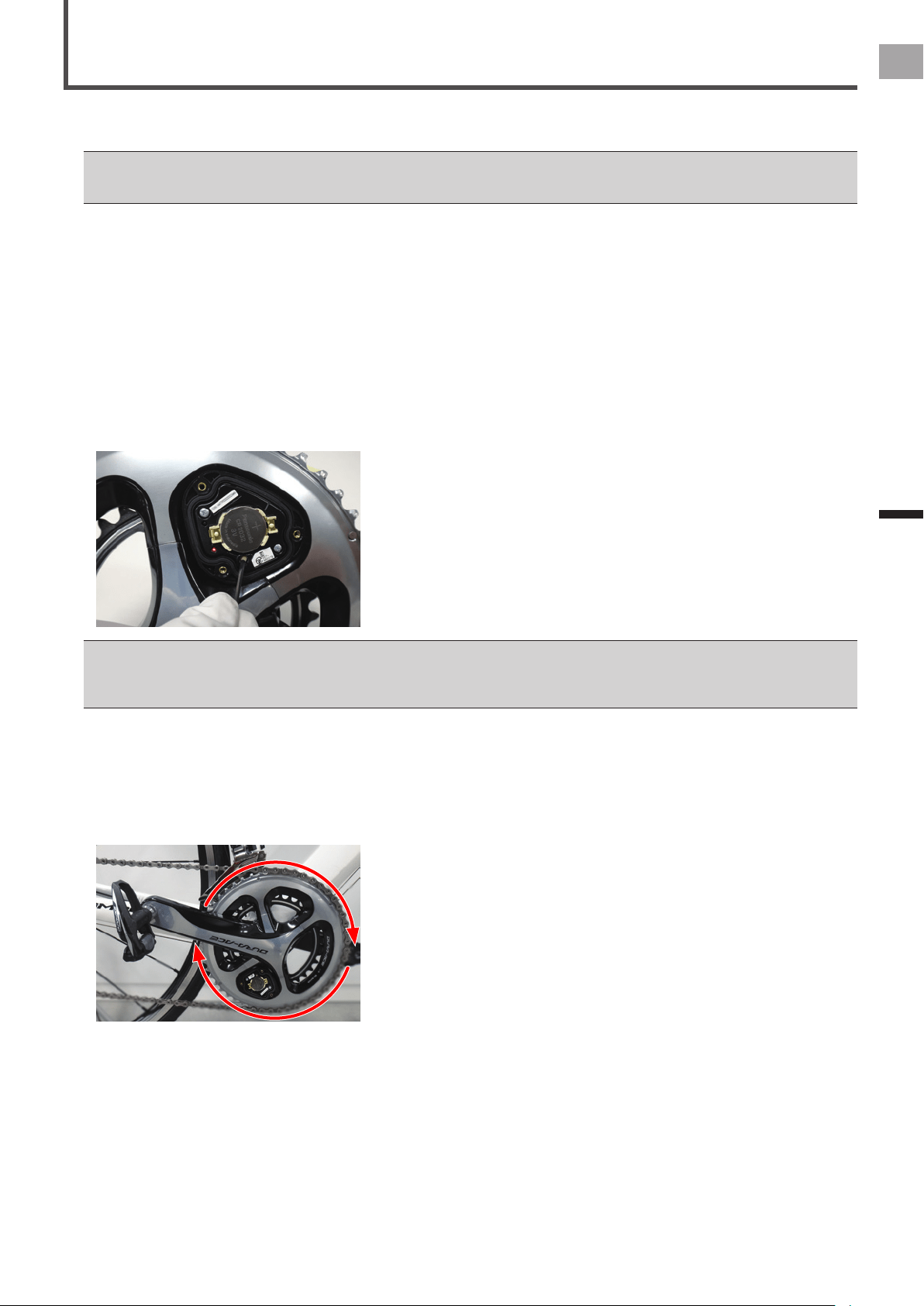
2
Remove the left transmitter’s cover.
Turn the cover to the left so the triangular arrow points to [OPEN] and remove it.
Be careful not to drop or lose the battery when removing the cover.•
3
Remove the batteries to check the conditions of the LEDs.
Left side Right side
After removing the batteries, do not re-install immediately, wait at least one minute and then install them again.•
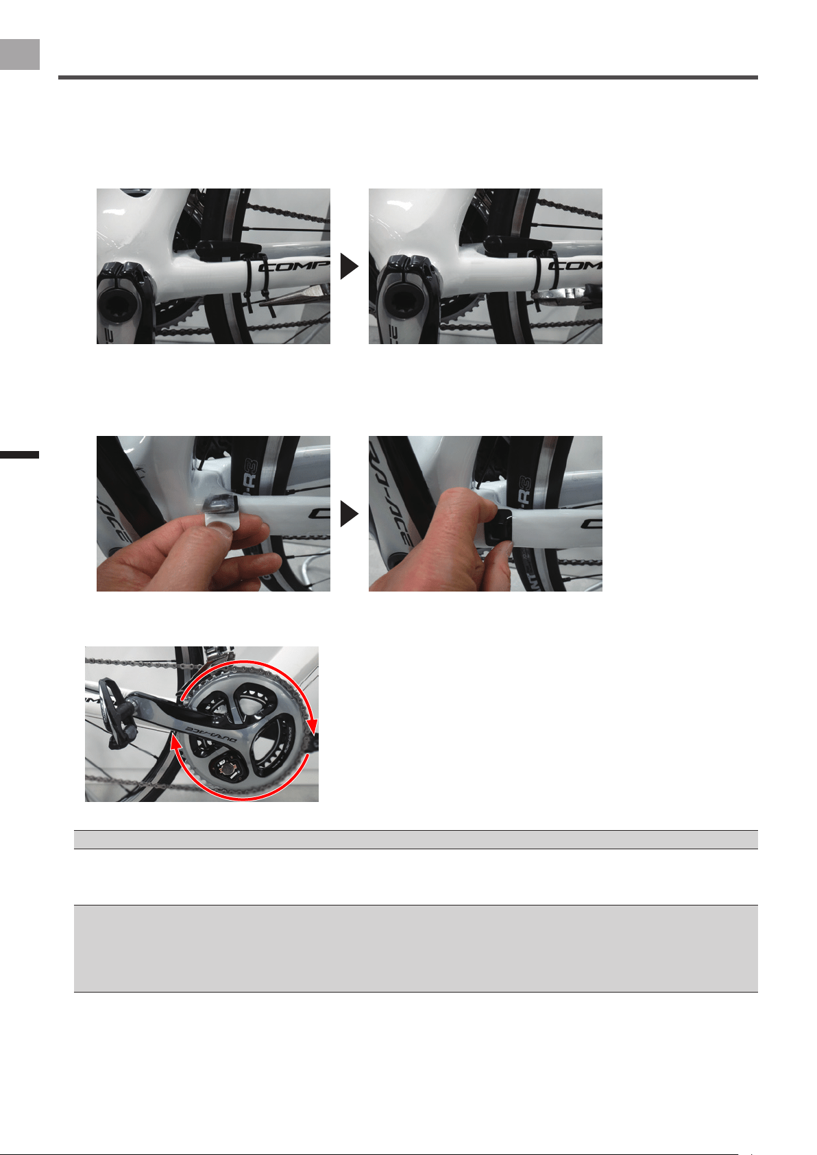
4
Install the batteries, and conrm that the LEDs light green for 10 seconds.
Right transmitter: Install the battery. However, do not install the battery cover at the moment, so you can check the LED.•
Left transmitter: After installing the battery, place the cover with the triangular arrow pointing to [OPEN], and turn it with •
coin to [CLOSE].
Left side Right side
Be careful not to drop or lose the battery when installing it.•
Do not use batteries other than CR2032.•
Install the cover rmly to ensure water resistant performance.•
Checking Operation of the Sensors
8
EN
Getting Ready
Checking Operation of the Sensors
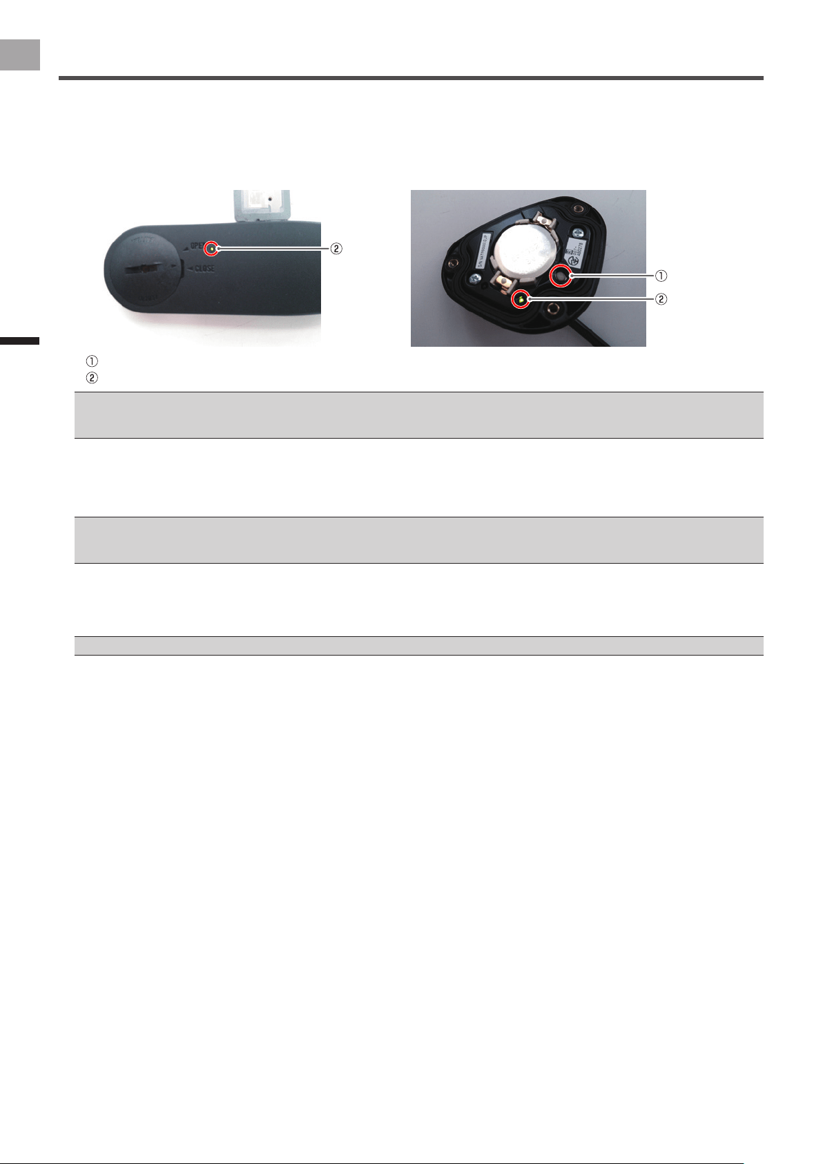
5
Push the push switch in the right transmitter for less than 2 seconds to conrm the sensor mode is set
to the pedaling monitor mode.
By pushing the push switch in the right transmitter for less than 2 seconds, the LEDs on the right transmitter blink green.
After that, if the LEDs light green for 10 seconds, the sensor is set to pedaling monitor mode.
Left side Right side
Push switch
LED
If the LEDs do not light for more than 5 seconds after installing the batteries, remove the batteries once, and after more than 1 minute, •
install them again. If the LEDs still do not light, the battery may be almost empty. Replace the battery with a new one.
If the LEDs light red, refer to Troubleshooting (page 25).•
If the LEDs light orange for 10 seconds, the sensor is set to power meter mode.
By pushing the push switch in the right transmitter for more than 2 seconds, the LEDs on the right transmitter blink green.
After conrming the blink, release the push switch. When the blinking stops, the LEDs on the left and right transmitters light
green for 10 seconds and the sensor mode changes to pedaling monitor mode.
If the pairing between the left and right transmitters fails, the LEDs blink red 5 times.•
Please do not push the push switch for more than 5 seconds. Doing so changes the mode to calibrate the magnet position.•
It may take about 10 seconds to switch the sensor mode depending on the radio transmission conditions.•
6
Install the right transmitter cover.
Use a tool that can measure the torque to tighten the screws.
Tightening torque: 30 cN•m•
Install the cover rmly to ensure water resistant performance.•
9
EN
Installing the Magnets
Installing the Magnets
Install the magnets on the bicycle.
There are two types of magnets, install one type on the bicycle.
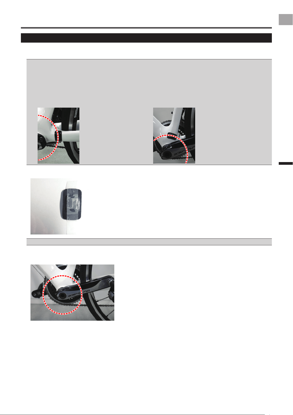
Checking the Position of the Magnets and Magnetic Sensors
This system measures the rotations of the cranks by magnets passing over magnetic sensors in the left and right transmitters.
Check the position of the magnets and the left and right magnetic sensors before installing the magnets on the bicycle.
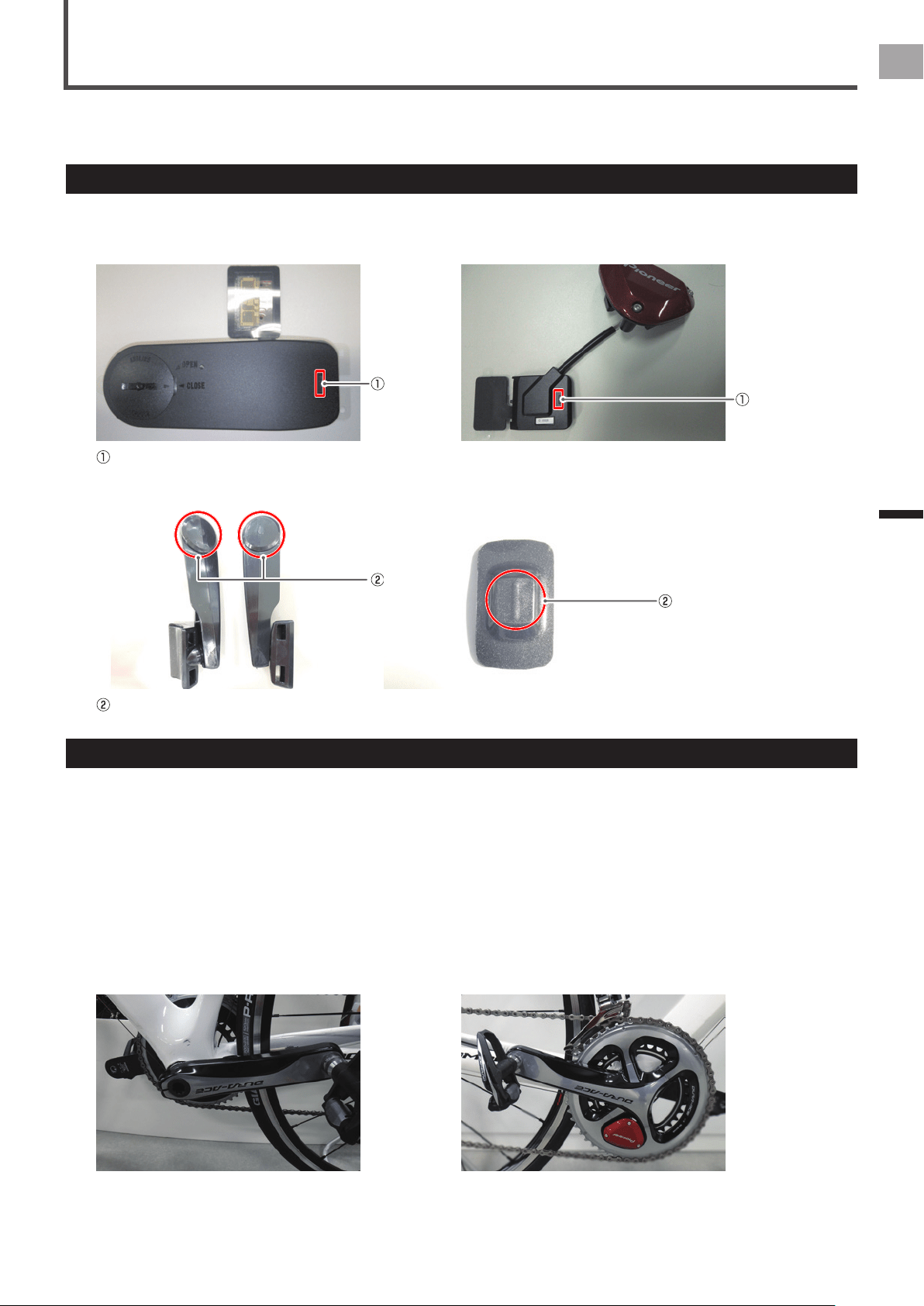
Magnetic sensor (left transmitter) Magnetic sensor (right-side junction box)
Magnetic sensors
Magnet (arm type) Magnet (patch type)
Magnets
Selecting the Type of Magnets
There are arm type and patch type magnets. The type that you can install on the chain stay depends on the shape of the bicycle.
This section explains how to chose the type of magnets to use.
1
Install the crank set, on which you have installed the sensors, on the bicycle.
Refer to the instruction manual for the crank set you are using for the procedure to install the crank set.
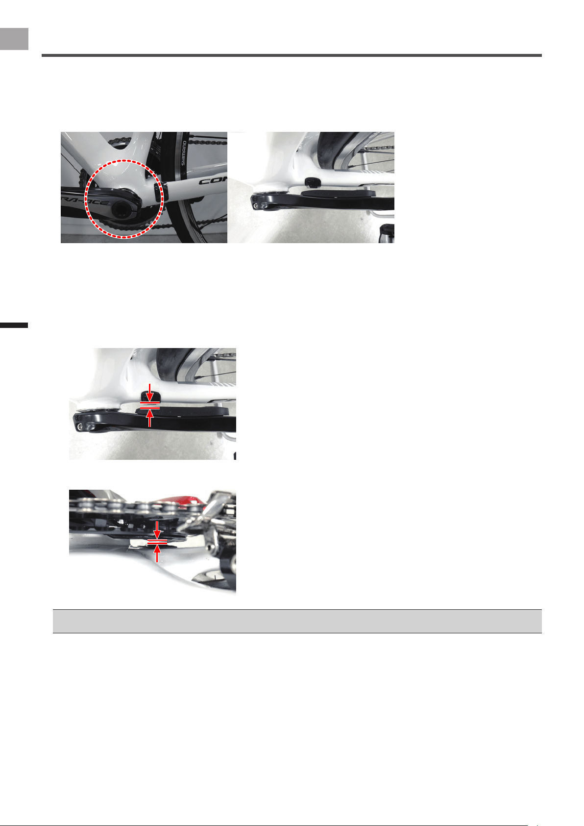
2
Adjust the position of the cranks.
Left side: Rotate the crank to the position where the crank lines up with the chain stay when looking at the crank from the •
side.
Right side: Rotate the crank to the position where the right transmitter lines up with the chain stay when looking at the •
crank from the side.
Left transmitter Right transmitter
10
EN
Installing the Magnets
Installing the Magnets
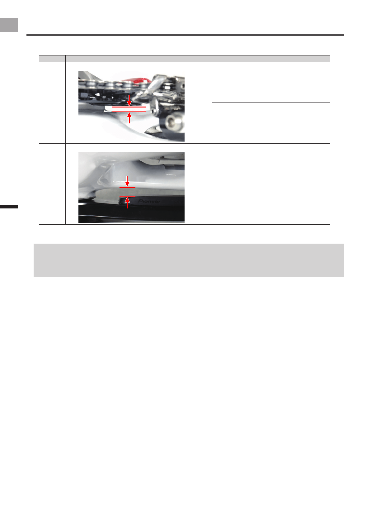
3
Select a type of magnet according to the following table.
Crank Position to measure Measured results Type of magnet
Right
Distance between chainring adapter and chain stay
Over 4.5 mm
Under 9.1 mm
Patch type
Over 1.5 mm Arm type
(*1)
Left
Distance between left transmitter and chain stay
Over 6 mm
Under 13.7 mm
Patch type
Over 3 mm Arm type
(*2)
*1 The chainring adapter and the arm type magnet must be installed so the distance between them is under 5.0 mm.
*2 The left transmitter and the arm type magnet must be installed so the distance between them is under 9.6 mm.
The patch type magnet may not be installable, depending on the shape of the chain stay. If this is the case, install the patch type magnet •
on the seat tube, or choose the arm type magnet.
If you install the patch type magnet on the seat tube, conrm that the position and results of the measurement are as shown below.•
Right side: Distance between chainring adapter and seat tube: Between 4.5 mm and 9.1 mm
-
Left side: Distance between left transmitter and seat tube: Between 6 mm and 13.7 mm
-
11
EN
Installing the Magnets
Installing the Magnets
Installing Patch Type Magnets
This section explains how to Install patch type magnets (temporarily).
The left crank is used as an example for this explanation, but the right crank uses the same procedure.
If the position in which you will install the patch type magnet is dirty, remove any dirt with cleaner before you install it.•
The patch type magnets can also be installed on the seat tube. If you install the patch type magnet on the seat tube, conrm that the •
position and results of the measurement are as shown below.
Right side: Distance between chainring adapter and seat tube: Between 4.5 mm and 9.1 mm
-
Left side: Distance between left transmitter and seat tube: Between 6 mm and 13.7 mm
-
The procedure to install the magnet on the seat tube is basically the same as installing it on the chain stay. However, if you install the •
magnet on the seat tube, be careful of its orientation. Install the magnets so their long sides align with the circle along which the magnetic
sensors pass.
Installed on chain stay Installed on seat tube
1
Apply masking tape to temporarily hold the magnet.
Do not remove the non-adhesive backing paper from the back of the magnet at this time.•
2
Rotate the crank set to conrm the position the magnetic sensor passes over.
The position to install the magnets is along the circle around which the magnetic sensors pass.
12
EN
Installing the Magnets
Installing the Magnets
3
Temporarily install the magnet on the chain stay.
Install the magnet on the chain stay so it is positioned on the circle conrmed in step 2.
Guideline for installation position (position over which magnetic sensors pass)•
Left side: Position on a radius about 53 mm from the center of the BB
Right side: Position on a radius about 42 mm from the center of the BB
4
Slowly rotate the crank set one rotation.
Conrm that the magnets do not interfere with the crank, transmitter or chainring adapter.
5
Conrm the position of the magnets.
Conrm that the magnets are positioned on a line square to the magnetic sensors. After that, measure the distance between
the magnet and magnetic sensor and the chainring adapter, and conrm it is within the following range.
Left side:•
Distance between the magnet and magnetic sensor: Between 3 mm and 10.7 mm
Right side:•
Distance between magnet and chainring adapter: Between 1.5 mm and 6.1 mm
If you cannot install it on a line square to the magnetic sensor, because the chain stay is angled or for some other reason, use a patch •
type magnet and install it on the seat tube.
This completes the temporary installation of the magnet on the chain stay.
After you have completed the temporary installation of the right and left magnets, calibrate the magnets and x them in
place (page 15).
The magnets are only temporarily attached, they must be calibrated and xed in place.
13
EN
Installing the Magnets
Installing the Magnets
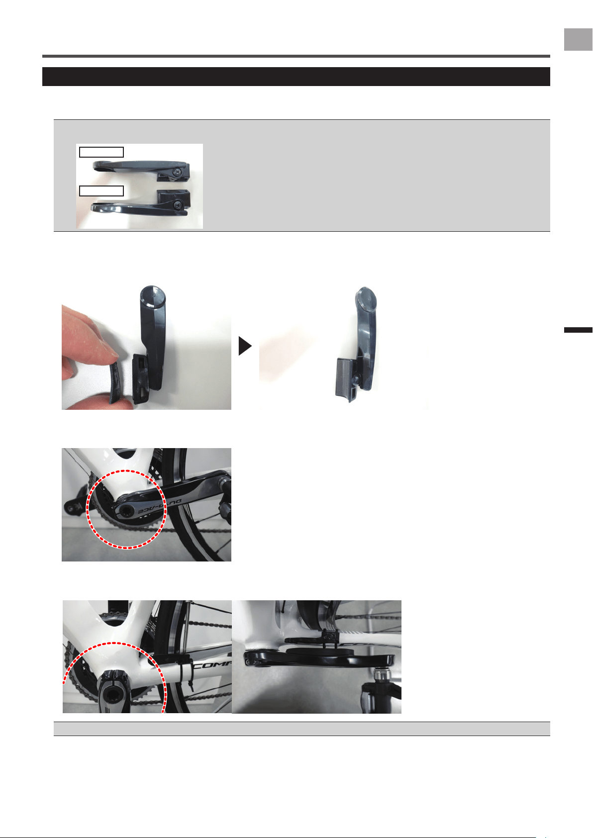
Installing Arm Type Magnets
This section explains how to install arm type magnets (temporarily).
The left side of the bicycle is used as an example for this explanation, but the right side uses the same procedure.
The position of the arm type magnets must be checked periodically.•
The left and right side arm type magnets have different shapes. They do not operate correctly if they are installed reversed left to right.•
Left side
Right side
1
Attach the cushion provided to the magnet’s arm.
Remove the non-adhesive backing paper from the cushion and stick it to the base of the arm (the part that touches the
chain stay).
2
Rotate the crank set to conrm the position the magnetic sensor passes over.
The position to install the magnets is along the circle around which the magnetic sensors pass.
3
Temporarily install the magnet on the chain stay.
Use the cable ties provided to install the magnet on the chain stay so it is positioned on the circle conrmed in step 2.
You need to adjust the position of the magnets to conrm their operation, so do not tighten the cable ties too much.•
14
EN
Installing the Magnets
Installing the Magnets
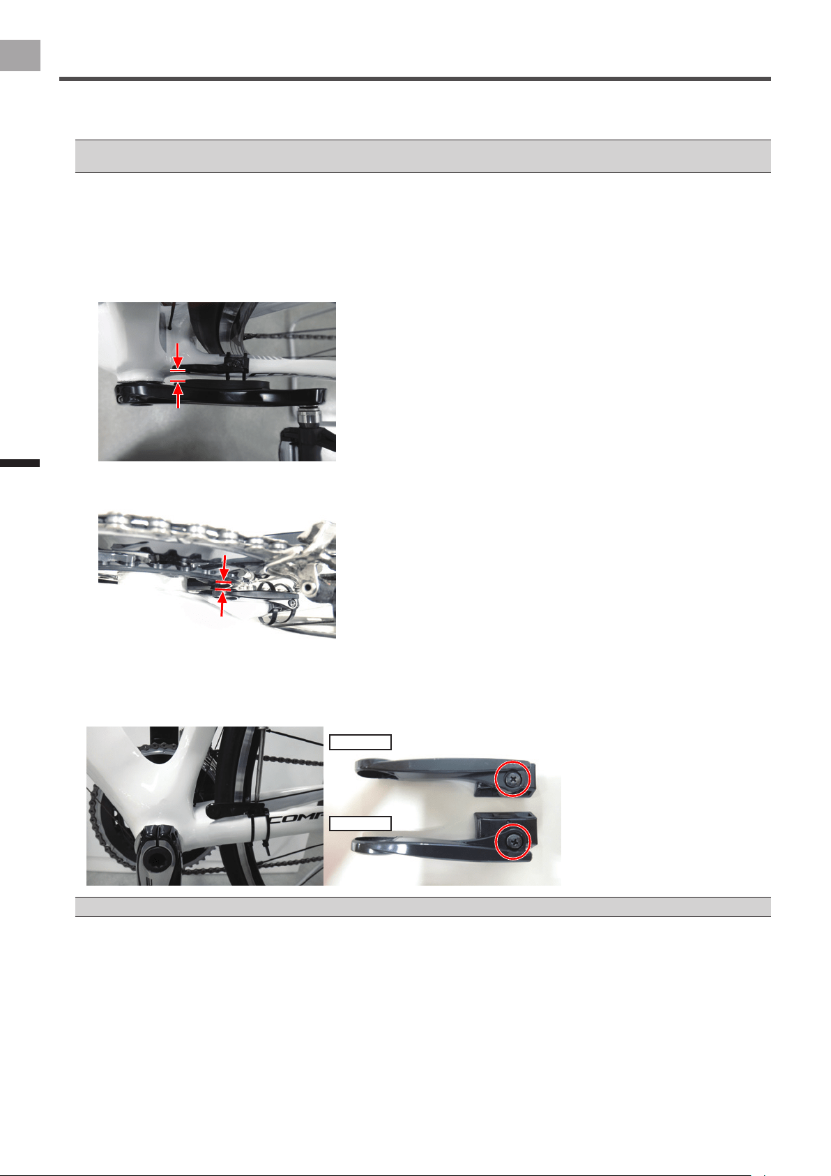
4
Slowly rotate the crank set one rotation.
Conrm that the magnets do not interfere with the crank, transmitter or chainring adapter.
Use a pair of snips to cut the excess parts off the magnet's cable ties if they interfere with the crank, transmitter or chainring adapter. •
When you do this, remember to leave a long enough piece of the cable tie so you can tighten it.
5
Adjust the position of the magnets.
Adjust the position of the magnets so they are positioned on a line square to the magnetic sensors.
After that, measure the distance between the magnet and magnetic sensor and the chainring adapter, and conrm it is
within the following range.
Left side:•
Distance between the magnet and magnetic sensor: Between 3 mm and 9.6 mm
Right side:•
Distance between magnet and chainring adapter: Between 1.5 mm and 5.0 mm
If the chain stay is angled, or for some other reason, loosen the screw on the base of the magnet to adjust the angle. After
adjusting the angle, tighten the screw to the specied torque.
Tightening torque: 30 cN•m•
Left side
Right side
Do not adjust the angle of the arm type magnet to more than XX° from the chain stay.•
This completes the temporary installation of the magnet on the chain stay.
Lightly tighten the cable ties so the temporarily installed magnet does not move.
After you have completed the temporary installation of the right and left magnets, calibrate the magnets and x them in
place (page 15).
The magnets are only temporarily attached, they must be calibrated and xed in place.
15
EN
Installing the Magnets
Calibrating the Magnets and Fixing Them in Place
Switch the sensors to magnet calibration mode, then conrm that the temporarily attached magnets are operating correctly. After
you conrm the magnets are operating correctly, x the magnets in place and then calibrate them.
The patch type magnets cannot be removed and re-attached once they are xed in place. Before you x the magnets in place, carefully •
conrm the positions where they are installed.
The position of the arm type magnets must be checked periodically after they are xed in place.•
1
Place the bicycle in a level place and mount it on something like a trainer.
Adjust the front wheel so that the front and back wheels are the same height.
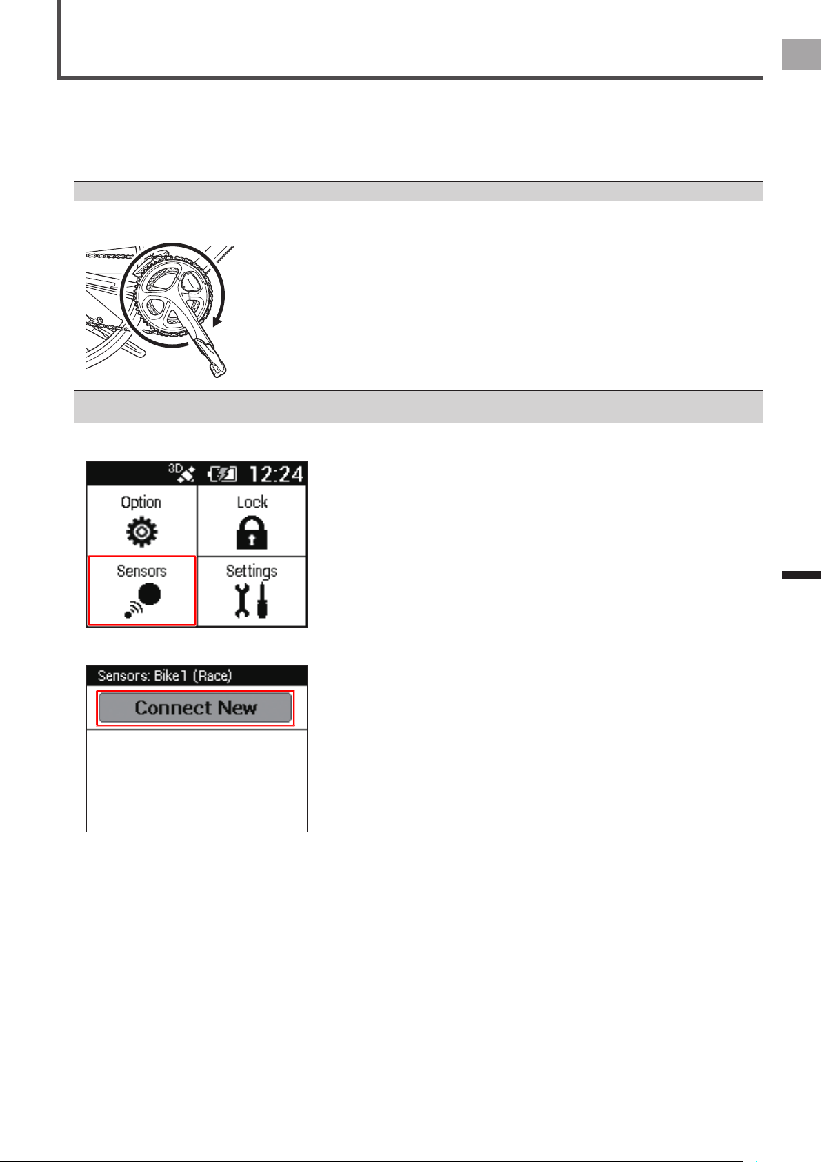
2
Rotate the bicycle’s crank set at least three rotations to activate the left and right transmitters.
3
Conrm that right and left transmitters are in the “Pedaling Monitor” mode.
See “Checking Operation of the Sensors” (page 7) regarding how to conrm the modes.
Next, leave the right transmitter’s cover, which you removed to conrm the mode, off and continue to the next step.
4
Press and hold down the switch on the right transmitter for at least 5 seconds.
The LED ashes orange 3 times, and the sensor switches to the magnet calibration mode.
The sensor stays in the magnet calibration mode for 30 minutes after the LED ashes. If you do not nish calibrating the
magnets within 30 minutes, switch the sensor to the magnet calibration mode again.
If the left and right transmitters cannot communicate, the right transmitter's LED ashes red ve times.•
Power cannot be measured while the sensor is in the magnet calibration mode.•
If you briey press the switch while in the magnet calibration mode, the left and right transmitter's LEDs ash orange 5 times, and the •
sensor exits the magnet calibration mode. The calibration data is destroyed when this happens.
5
Rotate the bicycle’s crank set slowly at about 30 rpm, and conrm that the LED lights green for each
rotation.
If the LED lights green, then the magnet sensors are correctly recognizing the magnets. Continue to the next step.
If the LED lights red, then you are turning the crank set too fast. Turn it slowly at about 30 rpm.
If the LED does not light, then the magnet sensors are not correctly recognizing the magnets. Refer to “Installing the
Magnets” (page 9), and check if the magnets are installed in the correct positions.
6
Rotate the bicycle’s crank set at least four more rotations.
Conrm that the LED lights green for each rotation.
Continue to the next step to x the magnets in place.
16
EN
Installing the Magnets
Calibrating the Magnets and Fixing Them in Place
7
Fix the magnets in place.
Be careful not to move the magnets from their adjusted positions when you x them in place.
Arm type•
Use needle nose pliers to tighten the cable ties to x the magnets in place, then use snips to cut off the excess parts of
the cable ties.
Patch type•
Keep the magnet attached to the tape as you lift up the tape. When you do this, leave one side of the masking tape
attached, so the magnets remain in their adjusted positions.
Remove the non-adhesive backing paper from the back of the magnet, and then re-stick the masking tape back the way
it was. Press on the magnet, through the masking tape, to x it in place, then remove the masking tape.
8
Rotate the bicycle’s crank set slowly at about 30 rpm, and conrm that the LED lights green for each
rotation.
Conrm that the left and right LEDs light green for at least seven rotations.
If the LED lights red, then you are turning the crank set too fast. Turn it slowly at about 30 rpm.•
9
Press and hold down the switch on the right transmitter for at least 5 seconds.
The LEDs light green for 10 seconds. The calibration data is saved and the sensor exits the magnet calibration mode.
In step 8, if you rotate the crank fewer than 6 rotations or if there are vibrations while calibrating the magnet, the LED lights red for 10 •
seconds and the sensor exits the magnet calibration mode. You must re-calibrate the magnets.
To exit the magnet calibration mode while calibrating, briey press the switch during the calibration. The left and right transmitters' LEDs •
ash orange 5 times, the calibration data is destroyed and the sensor exits the magnet calibration mode.
In addition, 30 minutes after switching to the magnet calibration mode, the calibration data is destroyed and the sensor exits the magnet
calibration mode.

17
EN
Installing the Magnets
Calibrating the Magnets and Fixing Them in Place
10
Install the right transmitter’s cover.
Use a tool to measure the torque when you tighten the screws on the right transmitter’s cover.
Tightening torque: 30 cN•m•
Install the cover rmly to ensure water resistant performance.•
This completes the calibration of the magnets and xing them in place.

18
EN
Pairing and Calibrating
Pairing and
Calibrating
Before Pairing and Calibrating
This section describes how to pair and calibrate the pedaling monitor sensor that is installed on the bicycle to the Cyclocomputer
SGX-CA500.
See the User’s Manual or the User’s Guide (online manual) of the Cyclocomputer SGX-CA500 regarding how to operate it.•
Pairing and Calibrating Procedure
Use the following procedure to pair and calibrate the product.
1. Placing the bicycle in a secure work position (page 18)
2. Pairing the pedaling monitor sensor (page 19)
3. Calibrating the zero point (page 23)
4. Checking the calibration (page 24)
Placing the Bicycle in a Secure Work Position
Place the bicycle in a level location, such as on a repair stand or indoor trainer.
Be sure to secure it so that it will not fall while you are working.
19
EN
Pairing and Calibrating
Pairing the Pedaling Monitor Sensor
This section describes how to pair the pedaling monitor sensor to the Cyclocomputer SGX-CA500.
It is necessary to pair the sensors on both the left and right sides. The right-side pedaling monitor sensor is used as an example
in this description. The procedure to pair the left side is the same as for the right side.
1
Check that the right transmitter and the left transmitter are in “Pedaling monitor mode”.
See page 7 to switch the modes.•
2
Rotate the bicycle’s crank set more than three rotations to start the left and right transmitters.
You have only 5 minutes to pair to the Cyclocomputer. If the transmitter stops while you are pairing, turn the crank set one revolution to •
start the transmitter and continue the pairing.
3
Press the [MENU] button on the SGX-CA500 and then tap [Sensors].
4
Tap [Connect New].
20
EN
Pairing and Calibrating
Pairing the Pedaling Monitor Sensor
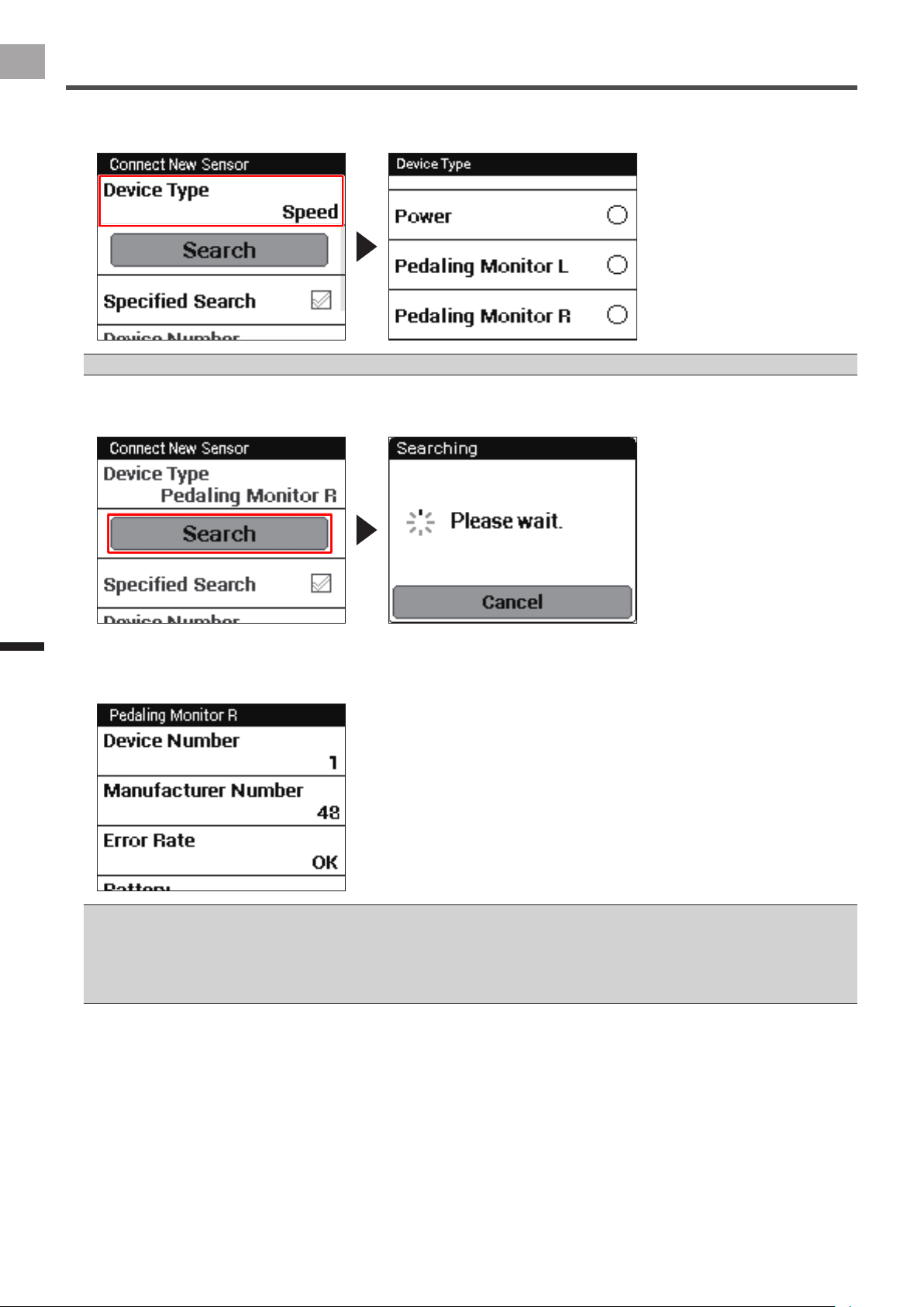
5
Tap [Device Type] and then [Pedaling Monitor R].
A list appears when you tap [Device Type]. Scroll down the list and then tap [Pedaling Monitor R].
For the left pedaling monitor sensor, press [Pedaling Monitor L].•
6
Tap [Search].
A [Searching. Please wait.] message appears. The information about the sensor appears when the sensor is found.
7
Check the information about the sensor.
The pairing is successful if the transmitters’ device numbers and the number in [Device Number] match and if “OK” appears
in [Error Rate].
See page 22 regarding the device numbers of the transmitters.•
If “Processing…” appears in [Error Rate], the information from the sensor is not being received correctly because transmission conditions •
are bad. Make sure that the sensor you are pairing is activated, then bring the SGX-CA500 closer to the sensor and do the pairing
operation again.
Pairing may fail because of interference in the 2.4 GHz band. If “Processing…” appears even while holding the sensor near the SGX-•
CA500 during pairing, try pairing it again in a location separated from any microwave ovens, wireless LAN, Wi-Fi, or other interference.
You may not be able to pair the sensor you want to pair if multiple sensors are activated. If this is the case, bring the SGX-
CA500 closer to the sensor you want to pair, or specify the device number. (page 21)
21
EN
Pairing and Calibrating
Pairing the Pedaling Monitor Sensor
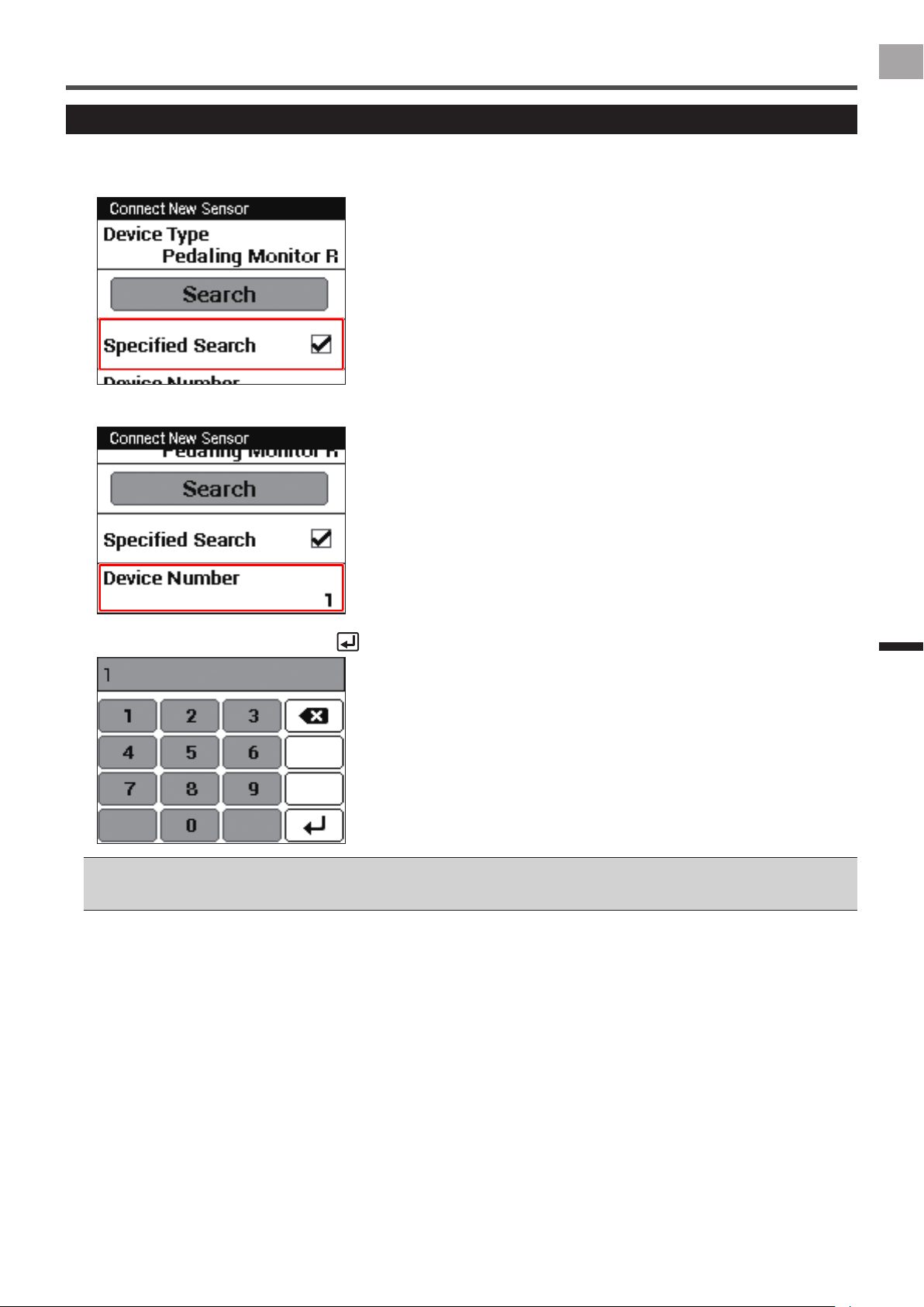
Specifying the Device Number to Pair it
To specify the device number of the sensor, do the following procedure before searching for the sensor.
1
Check [Specied Search] in the sensor’s pairing menu.
2
Tap [Device Number].
3
Enter the device number and tap .
See page 22 regarding the device numbers of the transmitters.•
When you input the device number, make sure that the number you specify is displayed in [Device Number] on the sensor’s information •
conrmation screen.
22
EN
Pairing and Calibrating
Pairing the Pedaling Monitor Sensor
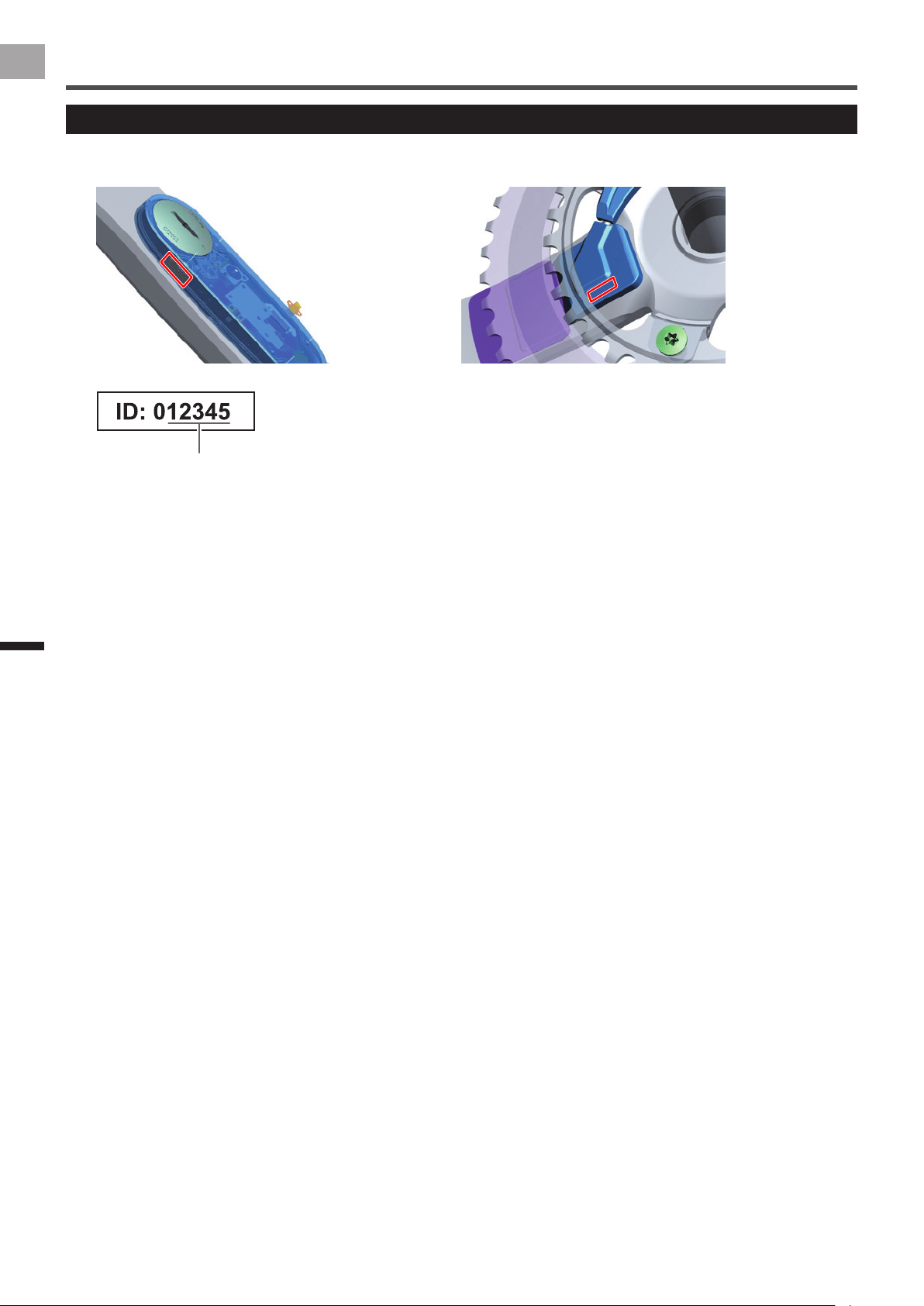
Checking Device Numbers
Device numbers are used when you specify the sensor’s device number to pair it to the Cyclocomputer.
Left side: Transmitter Right side: Junction box
Device number

23
EN
Pairing and Calibrating
Calibrating the Zero Point
This section describes how to use the Cyclocomputer SGX-CA500 to calibrate the zero point of the pedaling monitor sensor that
is installed on the bicycle. Zero point calibration is a function to store the zero point (no-load), where no forces act on the crank,
in the sensor memory.
The right-side pedaling monitor sensor is used as an example in this description. The procedure to calibrate the left side is the same as •
for the right side.
Please do not push the push switch in the right transmitter while calibrating the sensor or showing [Force Preview] with the •
Cyclocomputer SGX-CA500.
1
Mount the bicycle on a trainer or some other safe stand.
2
Position the crank arm so it is perpendicular to the ground, pointing downward.
3
In the sensor screen of the SGX-CA500, tap [Pedaling Monitor R] and then [Calibration (Zero)] in order.
4
Tap [Start Calibration].
The calibration starts.
If the calibration is successful, “Success” appears in the [Result] eld.
If “Failure” is displayed, the sensor may be calibrated in unstable condition that the crank is moving. Calibrate again with the
crank stopped.
This product has a correction function for the zero point uctuation caused by varying temperatures. The accuracy of this function •
improves when the sensor is calibrated in different temperatures. This function cannot measure correctly if you calibrate or check the
sensor before it is acclimated to the outside temperature.
The right side pedaling monitor sensor calibration is nished. Calibrate the left side in the same way.
After nishing the calibration of the pedaling monitor sensors on both sides, check the calibration (page 24).
Calibration
24
EN
Pairing and Calibrating
Checking the Calibration
Check that the sensors were calibrated correctly.
It is necessary to check the calibration of the sensors on both the left and right sides. The right-side pedaling monitor sensor is
used as an example in this description. The procedure to check the left side is the same as for the right side.
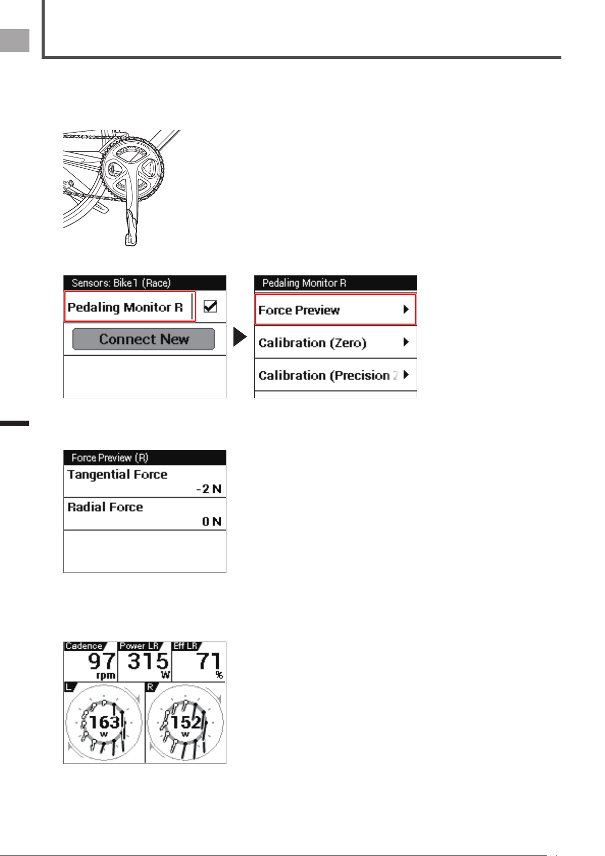
1
Position the crank arm so it is perpendicular to the ground, pointing downward.
2
In the sensor screen of the SGX-CA500, tap [Pedaling Monitor R] and then [Force Preview] in order.
3
Conrm that the values that appear on the SGX-CA500 Force Preview are within the range shown below.
Tangential Direction Force: 0 ± 3 N•
Radial Direction Force: 0 ± 3 N•
Checking the calibration of the right side is nished. Check the calibration of the left side in the same way.
After nishing the calibration, pedal a bicycle to conrm that the pedaling vector display appears. If the vector is not displayed,
perform the calibration again.

25
EN
Troubleshooting
Troubleshooting
Troubleshooting
Refer to the following suggestions if you have any problems installing or using the product.
If you cannot solve the problem, please contact your dealer or visit our web site.
Installation
Symptom Cause
Solution
User Dealer
A sensor installed on the crank
set is coming into contact with
the frame, Di2 battery, brake,
or other provided component.
The frame is not supported.
Depending on the shape of
the frame being used, a crank
that has sensors installed may
not be installable because it
comes into contact with the
frame. Even when two frames
have the same model number,
a difference in size and/or
year may make installation
impossible.
When the Di2 battery is under
the chain stay, installation that
provides contact with the Di2
battery may not be possible.
Take your bicycle to your retailer and have its size measured to check whether
the frame is supported. Since actual measurement is required, a judgment
about whether a frame is supported cannot be made before the frame is sold.
The crank set is obstructing
the transmitter and cover.
The crank set is not supported. Contact your dealer. Before selling the product, conrm that
the crank set is supported.
Shimano genuine chainrings are
supported.
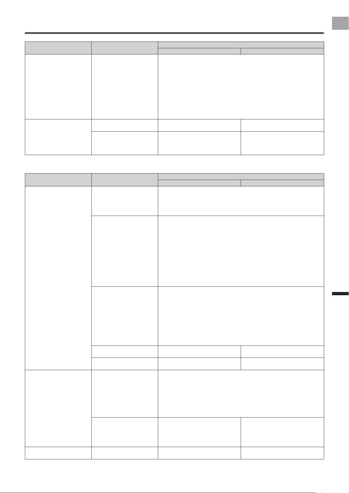
I cannot assemble the outer
chainring correctly.
The installation has been done
incorrectly.
Contact your dealer. The gap between the junction box and
the outer chainring is too narrow.
Refer to the documentation for the
crank set when assembling the chain
ring, and install it so the spider arm
does not contact the junction box.
There is a noise when I am
riding. The transmitter and
cover rattle.
The screws for installing the
sensor have become loose.
The double-sided tape or the
parts of the sensors have
deteriorated.
Contact your dealer.
You may need to replace the double-
sided tape or the parts of the sensors
if they deteriorate. (This is a paid
service.)
Check the screws for xing the right
transmitter, and then retighten them.
Check if the parts of the sensors are
installed correctly.
If replacements are needed, please
visit our website.
The chain ring rattles. The crank set is not correctly
assembled. The chain ring
adapter is not correctly
installed. The chain ring bolt
has become loose.
Contact your dealer. Check if the chain ring adapter is
installed correctly. Press on the
chainring in a clockwise direction
to eliminate any play as you tighten
the chainring bolts to the specied
torque. Retorque the chain ring bolt
periodically. Refer to the documentation
for the crank set.
Fix the position of the right transmitter
after assembling the chainring.
When the right transmitter’s
cover and left battery’s cover
were installed, the seal was
weak.
The rubber gasket is
deteriorating.
We recommend periodically replacing
the rubber gaskets inside the right
transmitter and left transmitter’s battery
cover. (This is a paid service.)
Using the equipment while the rubber
gaskets have deteriorated may
damage the product.
Contact your dealer.
Replace the rubber gaskets.
If replacements are needed, please
visit our website.
There is sand or oil on
the rubber gasket in the
transmitter.
― It is necessary to replace the rubber
gaskets if bicycle oil, cleaner, mud, or
sand has gotten on them, even if they
are not deteriorated. (This is a paid
service.)
Contact your dealer.
Replace the rubber gaskets.
If replacements are needed, please
visit our website.

26
EN
Troubleshooting
Troubleshooting
Magnet
Symptom Cause
Solution
User Dealer
I cannot install the magnet on
the chainstay.
The installation of the magnet
or the selected magnet type is
incorrect.
― There are two types of magnets, patch
type and arm type.
You need to choose the appropriate
type depending on the distance
between the magnet and the left
transmitter or the junction box, and the
shape of the frame.
The left transmitter and chain
ring adapter are obstructing
the magnet.
The installation of the magnet
or the selected magnet type is
incorrect.
― Measure the distance from the sensor
to the magnet, and install the magnet
correctly.
The arm type magnet rattles. The cable ties for xing the
magnet arm in place have
become loose. Or, the screws
for adjusting it have become
loose. Or, the cushions for
installation have deteriorated.
Contact your dealer. Check if the magnet is installed
correctly. The cable ties and cushions
are consumables. Replace them if
they have stretched or become loose
because of age or deterioration.
If replacements are needed, please
visit our website.
The magnet is rubbing. A stone or something is stuck
in the gap between the magnet,
transmitter, and junction box.
Remove any stones or other things stuck in the gap and use a damp rag to
clean the magnet and the sensor.
Stones or other things stuck in the equipment may damage it.
Magnet calibration fails. The magnet calibration was not
nished while in the magnet
calibration mode.
― Check the magnet calibration
mode. The system exits this mode
automatically after 30 minutes. Also,
pushing the push switch on the
right transmitter during the magnet
calibration mode cancels this mode
and the LEDs blink orange 5 times.
The left and/or right LEDs
light red when the magnet
calibration is nished.
The magnet has been detected
correctly less than 6 times.
― Conrm that the LEDs of the left and
right transmitters light green more than
7 times.
During magnet calibration, the
red LED lights when a magnet
passes a sensor.
Crank rotation is too fast. ― The crank rotation speed should be
less than one rotation per second.
During magnet calibration, the
LED does not light when a
magnet passes a sensor.
The installation of the magnet
has been done incorrectly.
― Check the magnet installation. The
LED will not light when the crank is
rotated if magnets are not positioned
correctly and/or if they are too far from
the sensor.
A magnet other than the
provided magnets is attached
to the frame.
― Check if there is a magnet other than
the provided magnets attached to the
frame. This product will not operate
properly if there are magnets installed
for another brand of power meter, etc.

27
EN
Troubleshooting
Troubleshooting
Sensor Connection
Symptom Cause
Solution
User Dealer
The pedaling monitor
sensor cannot pair to the
Cyclocomputer.
The sensor is in sleep state. Activate the transmitter by rotating the bicycle’s crank set at least three times.
The sensor automatically enters a sleep state if it is still for ve minutes.
There are no batteries in the
sensors.
Or, the positive and negative
terminals of the batteries are
reversed.
Conrm that the batteries (CR2032, 3V) are correctly installed in the left and
right pedaling monitor sensors. Insert the batteries with the + mark up. Press
on the right transmitter until you hear a click. After loading a battery into the
left transmitter, rotate the battery cover to its proper position. After loading
batteries, check to conrm that the LED is lit green.
The sensors’ batteries are
dead.
Replace the batteries. If the LED does not light for more than ve seconds after
batteries are loaded, remove the batteries, wait for at least one minute, and
then re-load them. If the LED still remains unlit, it means that battery power is
low. Replace the batteries with new ones.
Use Cyclocomputer sensor information to check the batteries. If the battery
level is 2.5 V or less under normal temperature, replace the batteries.
Battery voltage is reduced by low temperatures, which may result in unstable
operation.
The sensor’s operating mode
is not correct.
Check the operating modes of the left and right pedaling monitor sensors.
The device numbers are not
set correctly.
Check the device numbers of the left and right sensors, and then pair them
again.
There is a different 2.4 GHz
wireless device or a microwave
nearby.
Pairing may fail or require a long time because of the interference from
microwave ovens or other wireless devices. Move away from any other wireless
devices and move the sensor closer to the Cyclocomputer.
The attempt to pair to the sensor times out after 30 seconds. If they do not pair
after 30 seconds, move to a location where there is no electronic interference
and try to pair again.
The sensor and Cyclocomputer
are too far apart.
The sensors have a wireless range of about 10 meters, but this could be limited
by the existing radio wave environment. Move the sensor as close as possible
to the Cyclocomputer.
The Cyclocomputer does not
operate normally.
Check the Cyclocomputer’s charge and operations.
Conrm if a different ANT+ sensor can be paired.
The magnet is not installed
correctly.
Contact your dealer. Replace the batteries and check the
connection.
Wait for at least ve minutes until the
sensor enters the sleep state. Next,
rotate the crank at least three times
and check the connection again.
If a magnet is detected but does not
result in activation, check to make sure
that the magnet is installed correctly.
An incorrectly installed magnet may
result in improper operation.
The magnetic eld of the
magnet is weakening.
Contact your dealer. Check the distance between magnets
and the sensor.
Magnetism may have gotten weaker
due to age-related deterioration.
If operation is possible only when
the distance between magnets and
the sensor is closer than what is
prescribed, replace the magnets with
new ones.
Please visit our website for more
information.
The magnetic eld detector is
broken.
The junction cable of the right
sensor has been cut.
Contact your dealer. See “Calibrating the Magnets and
Fixing Them in Place” (page 15) of the
Installation Manual (for dealers).
If the sensor’s LED does not light,
please visit our website.
The circuit board in the
transmitter is broken.
Contact your dealer. See “Checking Operation of the
Sensors” (page 7) of the Installation
Manual (for dealers) .
If the sensor’s LED does not light,
please visit our website.
28
EN
Troubleshooting
Troubleshooting
Symptom Cause
Solution
User Dealer
The pedaling monitor sensor in
the power meter mode cannot
pair to a different company’s
cyclocomputer.
The other company’s
cyclocomputer does not
support ANT+ power meter.
Check that the Cyclocomputer being used supports pairing with the ANT+
power meter.
If it does, check the sensor operation mode. If the sensor is in the pedaling
monitor mode, set it to the power meter mode and connect it.
When the sensor is connected to another brand of Cyclocomputer, total power
and left/right balance can be displayed. Applied forces and pedal direction at
each rotation angle, and left/right pedaling efciency cannot be displayed. For
more information about this type of conguration, refer to the other brand of
Cyclocomputer’s user documentation.
The pairing of the left and right
sensors failed.
Press the right transmitter switch and check the sensor operation mode. After
conrming that the left/right LEDs light orange, connect the sensor to the
Cyclocomputer. If the LEDs do not light orange, change the operation mode.
After you load batteries, the sensors start in the pedaling monitor mode.
The red LEDs light for 10
seconds when batteries are
inserted.
Something is wrong with the
strain gauge unit.
The circuit board in the
transmitter is broken.
There is something wrong with
the circuit board of the junction
box or junction cable for the
right sensor.
Contact your dealer. Please visit our website.
Calibration
Symptom Cause
Solution
User Dealer
Zero point calibration fails. There are loads on the cranks
or pedals.
Stop the bicycle, remove any load from the cranks and pedals, and then
calibrate it. It may fail if a load is applied.
Water inside the sensors. Water can get into the sensors when the right transmitter cover and/or the left
transmitter battery cover are not attached correctly. Remove the batteries. After
the interior of the sensors are sufciently dry, perform zero point calibration
again.
Something is wrong with the
strain gauge unit.
The circuit board in the
transmitter is broken.
There is something wrong with
the circuit board of the junction
box or junction cable for the
right sensor.
Contact your dealer. Please visit our website.
Zero point calibration does not
nish.
The sensor and Cyclocomputer
pairings are not stable.
Information may not be sent correctly to the sensor depending on the radio
wave environment and the distance between the Cyclocomputer and the
sensor. Stop the zero point calibration and move the Cyclocomputer closer
to the sensor or do the calibration again in a location with a better radio wave
environment.
The force preview is not near
0 N after calibrating the zero
point in pedaling monitor mode.
There are loads on the cranks
or pedals.
Stop the bicycle, remove any load from the cranks and pedals, and then
calibrate it. The zero point may be incorrect if a load is applied.
Zero point calibration fails in
power meter mode.
There are loads on the cranks
or pedals.
Position either the left or right crank at 6 o’clock before calibrating from the
Cyclocomputer. For more information about calibration, refer to the other brand
of Cyclocomputer’s user documentation.
Check that there are no loads on either the left or right cranks or pedals.
Calibration fails if there is a load on either the left or right cranks or pedals,
because the left and right zero point is calibrated at the same time for the
power meter mode.
This is a problem with either
the left or right sensor.
Contact your dealer. The zero point calibrations are done
at the same time for the power meter
mode. The zero point calibrations may
fail if either the left or right sensor is
faulty.
Please visit our website.
29
EN
Troubleshooting
Troubleshooting
Symptom Cause
Solution
User Dealer
The torque chart is not near 0
N after calibrating zero point in
power meter mode.
There are loads on the cranks
or pedals.
Position either the left or right crank at 6 o’clock before calibrating from the
Cyclocomputer. For more information about calibration, refer to the other brand
of Cyclocomputer’s user documentation.
Remove any load from the left and right cranks and pedals, and then calibrate
the zero point. The zero point may be incorrect if a load is applied.
The zero point may be incorrect if there is a load on either the left or right
cranks or pedals. Because the left and right zero point is calibrated at the same
time for the power meter mode.
The value that is displayed following calibration with another brand of
Cyclocomputer is the total of the left/right calibration values. Values may vary
somewhat due to temperature and the crank angle, but this is normal.
The torque value does not
appear correctly if there are
loads on the cranks or pedals
when paired to a different
company’s cyclocomputer
while in the power meter mode.
The crank length is not set
correctly.
Contact your dealer. Please visit our website.
The calibration may not have
been done correctly.
Contact your dealer. Please visit our website.
Display
Symptom Cause
Solution
User Dealer
The power value is not correct.
The left and right sides of
the vector chart or efciency
display are obviously different.
The proportions of the left
and right power values are
obviously different.
When pedaling with only one
leg, the side not being pedaled
is extremely far from 0 W.
The zero point is incorrect. Installing the cranks and pedals can cause a slight change in the zero point.
Be sure to calibrate the zero point after installing cranks and pedals.
When using the pedaling monitor mode, calibrate the zero point for both the left
and right sensors.
Calibrate the zero point with pedals installed.
Temperature (air temperature)
learning is not performed.
If there has been a change in temperature of 4°C or more since the last zero
point calibration, calibrate the zero point again. Also, accurate measurement
will not be possible if calibration is performed before the sensor is acclimated to
external air temperature. It takes at least 20 minutes for the sensor to become
acclimated to the current outside temperature.
This device uses a temperature (air temperature) learning function to
automatically calibrate its zero point as the temperature changes. This
function maintains accuracy as the temperature changes during a ride. As the
temperature varies, it is necessary to calibrate the zero point more than twice,
so the most recent six times are used for calibrating using this function. The
results of the zero point calibration are recorded if the temperature varies more
than 4°C from the zero point calibration recorded previously.
There is a problem with the
temperature (air temperature)
learning result.
Check if a change in temperature has caused a change in the zero point.
After the crank has become sufciently acclimated to the external temperature,
check the Force Preview. Next, move to a location where the external
temperature is different, wait for 20 minutes, and then check the Force Preview
again.
If there is a major difference between the zero points, it could mean there is a
problem with the learning function. If this happens, use the ZeroCal application
to initialize the sensor whose zero point is off. Learning function results are
stored in a log le, and can be checked using the Cyclo-Sphere screen and the
device information window.
The calibration under load may
not have been done correctly.
Contact your dealer. Please visit our website.
This is a problem with either
the left or right sensor.
Contact your dealer. Please visit our website.
The power value and/or vector
are not displayed occasionally.
The sensors’ batteries are
dead.
Replace the batteries. If the LED does not light for more than ve seconds after
batteries are loaded, remove the batteries, wait for at least one minute, and
then re-load them. If the LED still remains unlit, it means that battery power is
low. Replace the batteries with new ones.
Use Cyclocomputer sensor information to check the batteries. If the battery
level is 2.5 V or less under normal temperature, replace the batteries.
Battery voltage is reduced by low temperatures, which may result in unstable
operation. Frequent replacement of batteries is recommended during winter.
A magnet other than the
provided magnets is attached
to the frame.
Contact your dealer. Check if there is a magnet other than
the provided magnets attached to the
frame. This product will not operate
properly if there are magnets installed
for another brand of power meter, etc.
The vector chart is rotating. The magnet calibration may
not have been done correctly.
Contact your dealer. Check if the magnets are installed
correctly. Correctly calibrate magnets.

30
EN
Troubleshooting
Troubleshooting
Symptom Cause
Solution
User Dealer
The vector data does not
update every few seconds.
The sensor and Cyclocomputer
pairings are not stable.
The sensor information may not be received correctly, depending on the
radio wave environment. Conrm it in a location that has a good radio wave
environment.
When one of the pedals is
pushed, the vector display
of the other pedal becomes
inconsistent.
This is according to the
specications.
A vector may be displayed based on the pedal’s weight and centrifugal force.
There is a deviation of several
watts when compared to the
power values from a different
brand of power meter.
This is according to the
specications.
Certain measurement methods and/or use conditions may generate deviation
with another brand of power meter.
The cadence does not appear
on the Cyclocomputer when
rotating the cranks slowly.
This is according to the
specications.
It is not possible to measure the cadence if cranks are rotating very slowly.
The display remains on the
Cyclocomputer even when the
bike is stopped and the cranks
are stopped.
This is according to the
specications.
Information may be displayed for 2 to 3 seconds after stopping.
The display does not appear on
the Cyclocomputer immediately
after I start pedaling.
This is according to the
specications.
When you start pedaling, the crank needs to rotate to detect the magnet more
than two times. After that, a packet of data is sent for every rotation of the crank
when the crank is pointing directly up (12 o’clock). Also, a maximum of a 2
second delay may occur from when data is sent to the Cyclocomputer to when
it is displayed.
Occasionally, only the left/
right power value is displayed,
without vector data on the
Cyclocomputer and/or Cyclo-
Sphere.
This is according to the
specications.
The product uses three ANT transmissions to send power values and vector
data. The rst transmission sends the power value, while the second and third
transmissions send vector data. The Cyclocomputer refreshes information
every second. If data for all three transmissions is available both the power
value and vector data are displayed, but transmission timing may result in only
the power value being displayed. This is because the product is designed to
display and record information as quickly as possible, even if only a power
value is available. When pedaling starts out after a stop at a trafc light or
after the crank is paused while riding, only the power value may be displayed
due to poor wireless LAN connection conditions. Depending on the crank start
position when pedaling is started, display of either the left or right pedal may be
delayed.
The initial display of the left
and right sensors are different
on the Cyclocomputer.
This is according to the
specications.
The left and right displays may be 1 to 2 seconds out of sync depending on the
angle when pedaling starts.
The display does not update
every second when rotating
the cranks slowly.
This is according to the
specications.
If the cranks are rotating at less than 60 rpm the update will not happen every
second because data is sent for each rotation.
The display of the length of the
vectors is not consistent.
This is according to the
specications.
The reference for the maximum length of the vector is the largest force applied
in one rotation. The vector display may not be consistent if the force is small.
The efciency value falls if I
pedal on the outside of the
pedals.
This is according to the
specications.
Pedaling with your weight on the inside or outside of the pedal reduces the
accuracy of the measurement of the force in the radial direction because
the reference is the length of the pedal that was set when calibrating (radial
direction) with load. The efciency value may drop when pedaling with your
weight on the outside because the force measured in the radial direction is
larger than normal.

31
EN
Troubleshooting
Troubleshooting
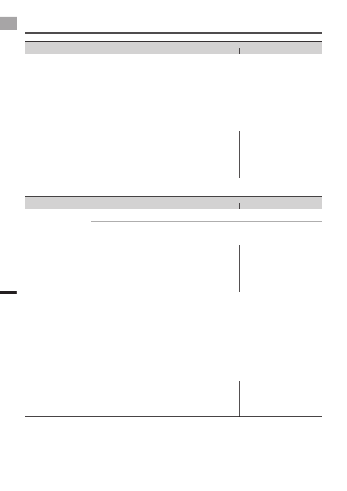
Error codes
An error code is displayed if an error occurs while setting the crank length or doing calibrations.
Code Description of error Data (radial) Data (tangential)
1 Parameter deviation (mass of load is 0) - -
2 Insufcient battery power - -
3 Failed to calibrate zero point (tangential and radial) 1: Error
0: Normal
1: Error
0: Normal
4 The zero point calibration is very different from the desired
value.
Multiple of detected value of force Multiple of detected value of force
5 Not used - -
6 Large disruption detected due to vibration during calibration Degree of instability of detected
value of force
Degree of instability of detected
value of force
7 Calibration with load was done before high accuracy zero point
calibration
- -
8 Exceeded measurement limit during load calibration Multiple of detected value of force Multiple of detected value of force
32
EN
Troubleshooting
Assembling the Chainring and Installing the Right Transmitter
Install the right transmitter on the right crank as you assemble the chainring.
If the chainring and chainring adapter have been removed, assemble the chainring and fasten the right transmitter according to
the following procedure.
Refer to the instruction manual for the crank set you are using for the procedure to assemble the chainring.•
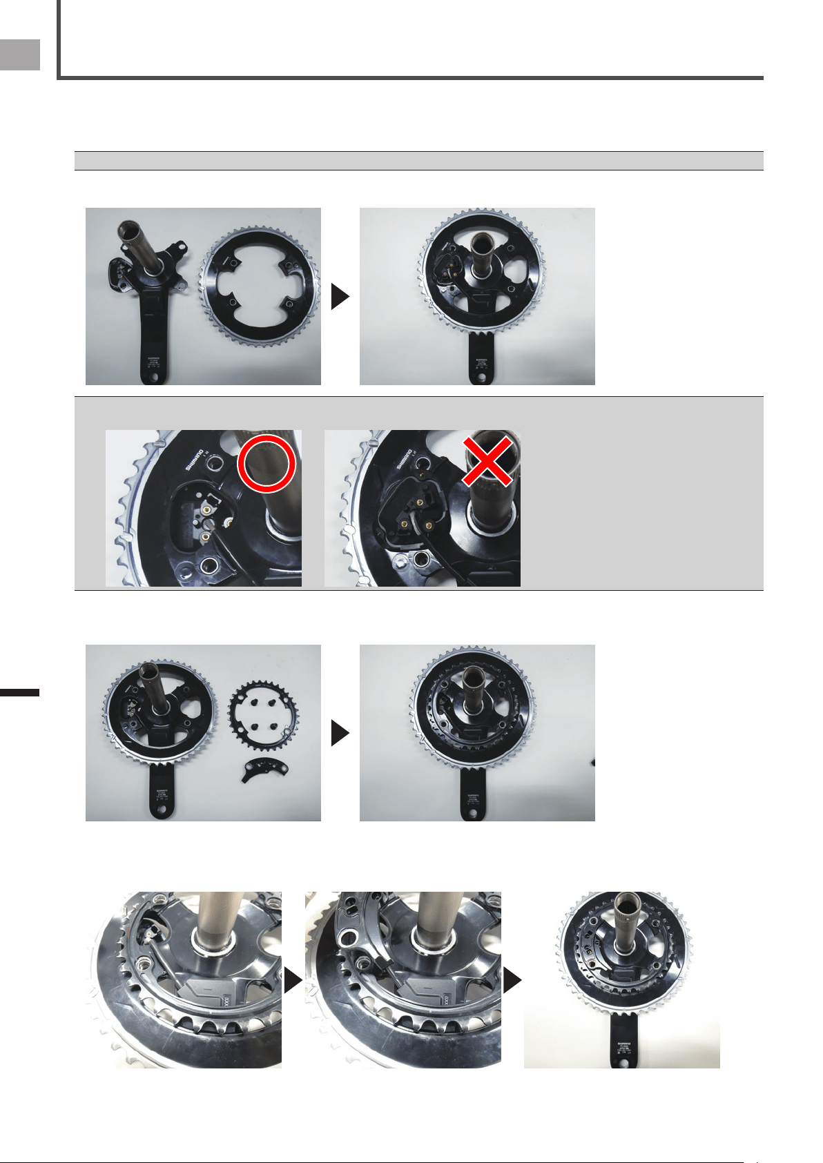
1
Install the outer chainring on the spider arm.
Install the right transmitter so it is on the outside of the chainring.•
Do not install the right transmitter on the inside of the chainring.
2
Install the inner chainring.
Do not insert the chainring bolt at this time.
3
Install the chainring adapter.
Run the junction cable along the guide of the chainring adapter, line up the bolt holes as you overlay the chainring adapter
over the inner chainring.
33
EN
Troubleshooting
Assembling the Chainring and Installing the Right Transmitter
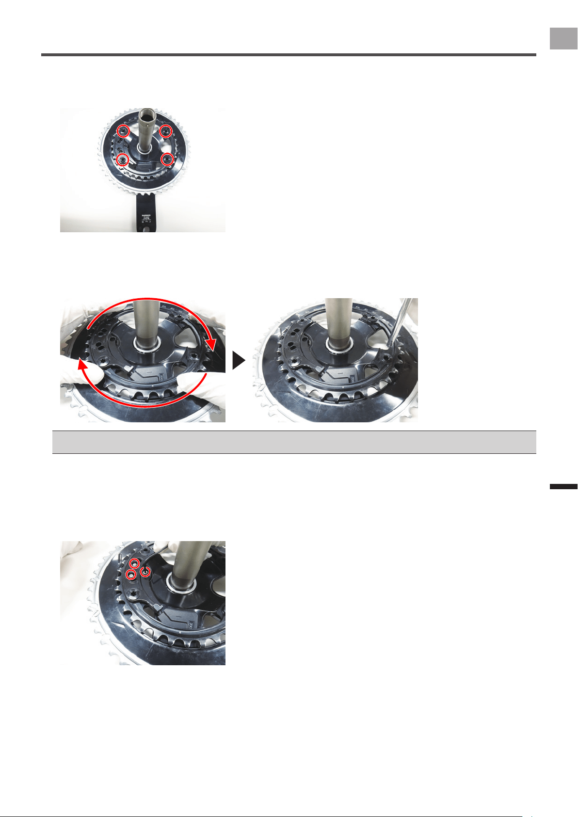
4
Insert the chainring bolts into the bolt holes and temporarily install the chainring adapter on the
chainring.
Do not tighten the chainring bolts too tightly when you temporarily tighten them.
5
Press on the chainring in a clockwise direction to eliminate any play as you tighten the chainring bolts
to the specied torque.
Tighten the chainring bolts in order in a kitty-corner pattern.
Tightening torque: 14 N•m•
Refer to the instruction manual for the crank set you are using for the torque at which to tighten the chainring bolts.•
Periodically inspect and re-torque the bolts on the chainring.•
6
Install the right transmitter on the chainring adapter with the 8-mm screws provided.
Check that the right transmitter is installed so it lines up with the chainring.
Press on the right transmitter from the outer side of the outer chainring as you insert the 3 screws, then tighten them to the
specied torque.
Use a tool to measure the torque when you tighten the screws.
Tightening torque: 30 cN•m•
This completes the installation of the sensors on the right crank set.

34
EN
Specications and Support
Specications
and Support
Care, Maintenance, and Storage
Use a soft dry cloth or a cloth that has been dampened and wrung out to wipe dirt from the left and right transmitters, the •
strain gauge unit cover, the magnet, and other accessories.
Do not use benzene, paint thinner, or other volatile chemicals, cleansers, or chemically treated cloths. Doing so could •
damage the product or cause the paint to peel off.
If you are not going to use the product for a long period of time, remove the batteries.•

35
EN
Specications and Support
Specications
Weight: About 66 g
Dimensions: Pedaling monitor sensor (right side):
Right transmitter:•
58.3 mm(W) × 46.1 mm(H) × 21.3 mm(D)
Junction box, Strain gauge unit cover:•
78 mm(W) × 36.7 mm(H) × 7.3mm(D)
Pedaling monitor sensor (left side):
92.5 mm(W) × 34.7 mm(H) × 8.6 mm(D)
Water resistant: This device has a water resistance rating of IPX-6/IPX-7.
Communications method (sensors): ANT+ wireless
Battery: CR2032
Operation temperature: −10 °C to 50 °C
ANT+ is a Wireless Personal Network protocol with very low power requirements using 2.4GHz frequency band.•
For more information, visit http://www.thisisant.com/
Specications and design are subject to possible modications without notice.•
Illustrations used in this manual may be different from actual ones.•

©2012 PIONEER CORPORATION.
All rights reserved.
<2013/7 A> EU
http://www.pioneerelectronics.com
http://www.pioneerelectronics.ca
http://www.pioneer.eu
Visit www.pioneer.eu to register your product.
Visitez www.pioneer.eu pour enregistrer votre appareil.
Si prega di visitare il sito www.pioneer.eu per registrate il prodotto.
Visite www.pioneer.eu para registrar su producto.
Zum Registrieren Ihres Produktes besuchen Sie bitte www.pioneer.eu.
Bezoek www.pioneer.eu om uw product te registreren.
PIONEER CORPORATION
1-1, Shin-ogura, Saiwai-ku, Kawasaki-shi, Kanagawa 212-0031, JAPAN
PIONEER ELECTRONICS (USA) INC.
P.O. Box 1540, Long Beach, California, 90801-1540, U.S.A.
TEL: (800) 421-1404
PIONEER ELECTRONICS OF CANADA INC.
340 Ferrier Street, Unit 2, Markham, Ontario, L3R 2Z5, Canada
TEL: 1-877-283-5901
TEL: 905-479-4411
PIONEER EUROPE NV
Haven 1087, Keetberglaan 1, B-9120 Melsele, Belgium/Belgique
TEL: +32 (0)3 570 05 11