Version 07/11 - Page 1
PELLICANO
Under Cabinet Rangehood
READ AND SAVE THESE INSTRUCTIONS
READ THESE INSTRUCTIONS BEFORE YOU START INSTALLING THIS RANGEHOOD
WARNING: - TO REDUCE THE RISK OF A RANGE TOP GREASE FIRE: a) Never leave surface units unattended at high settings. Boilovers cause
smoking and greasy spillovers that may ignite. Heat oils slowly on low or medium setting. b) Always turn hood ON when cooking at high heat
or when ambeing food (i.e. Crepes Suzette, Cherries Jubilee, Peppercorn Beef Flambé). c) Clean ventilating fans frequently. Grease should not
be allowed to accumulate on fan or lter. d) Use proper pan size. Always use cookware appropriate for the size of the surface element.
WARNING: - TO REDUCE THE RISK OF INJURY TO PERSONS IN THE EVENT OF A RANGE TOP GREASE FIRE, OBSERVE THE FOLLOWING *: SMOTHER
FLAMES with a close-tting lid, cookie sheet, or metal tray, then turn off the burner. BE CAREFUL TO PREVENT BURNS. If the ames do not go out
immediately EVACUATE AND CALL THE FIRE DEPARTMENT. NEVER PICK UP A FLAMING PAN - You may be burned. DO NOT USE WATER, including
wet dishcloths or towels - a violent steam explosion will result. Use an extinguisher ONLY if: 1. You know you have a Class ABC extinguisher, and
you already know how to operate it. 2. The re is small and contained in the area where it started. 3. The re department is being called. 4. You
can ght the re with your back to an exit. * Based on "Kitchen Firesafety Tips" published by NFPA
LISEZ BIEN CETTE FICHE AVANT D'INSTALLER LA HOTTE
AVERTISSEMENT - POUR MINIMISER LE RISQUE D’UN FEU DE GRAISSE SUR LA TABLE DE CUISSON : a) Ne jamais laisser
un élément de la table de cuisson fonctionner sans surveillance à la puissance de chauffage maximale; un renversement/
débordement de matière graisseuse pourrait provoquer une inammation et le génération de fumée. Utiliser toujours une
puissance de chauffage moyenne ou basse pour le chauffage d’huile. b) Veiller à toujours faire fonctionner le ventilateur
de la hotte lors d’une cuisson avec une puissance de chauffage élevée ou lors de la cuisson d’un mets à amber (i.e.
Crepes Suzette, Cherries Jubilee, Peppercorn Beef Flambé). c) Nettoyer fréquemment les ventilateurs d’extraction. Veiller
à ne pas laisser de la graisse s’accumuler sur les surfaces du ventilateur ou des ltres. d) Utiliser toujours un ustensile
de taille appropriée. Utiliser toujours un ustensile de taille adapté à la taille de l’élément chauffant.
AVERTISSEMENT: - POUR PRÉVENIR LES BLESSURES EN CAS DE FEU SUIVRE LES RECOMMANDATIONS SUIVANTES:
ÉTOUFFEZ LE FEU avec un couvercle métallique et fermez le brûleur. Si le feu ne s'éteint pas tout de suite, QUITTEZ
LES LIEUX ET APPELEZ LES POMPIERS. NE TOUCHEZ JAMAIS UNE CASSEROLE EN FLAMMES. N'UTILISEZ JAMAIS
DE L'EAU ou un torchon mouillé pour éteindre le feu - ce qui pourrait causer une explosion de vapeur. N'utilisez un
extincteur que si: 1. Vous avez un modèle ABC et vous connaissez bien son mode d'emploi. 2. Le feu est petit et peu
répandu. 3. Les pompiers sont déjà prévenus. 4. Vous avez une sortie derrière vous.
VENTING REQUIREMENTS
Flexible ductwork is not recommended. If it is used,
each foot of exible ductwork used is equivalent to
two feet of straight metal ductwork when calculating
the ductrun length. Thus, a exible elbow equals two
standard elbows.
WARNING - To Reduce The Risk Of Fire, Use Only Metal
Ductwork.
ELECTRICAL REQUIREMENTS
WARNING - TO REDUCE THE RISK OF FIRE OR ELEC-
TRIC SHOCK, do not use this fan with any solid-state
speed control device.
WARNING - TO REDUCE THE RISK OF FIRE, ELECTRI-
CAL SHOCK, OR INJURY TO PERSONS, OBSERVE
THE FOLLOWING: Use this unit only in the manner
intended by the manufacturer. If you have any ques-
tions, contact the manufacturer.
Before servicing or cleaning unit, switch power off at
service panel and lock the service disconnecting means
to prevent power from being switched on accidentally.
When the service disconnecting means cannot be
locked, securely fasten a prominent warning device,
such as a tag, to the service panel.
CAUTION: For General Ventilating Use Only. Do Not
Use To Exhaust Hazardous or Explosive Materials
and Vapors.
WARNING - TO REDUCE THE RISK OF FIRE, ELECTRI-
CAL SHOCK, OR INJURY TO PERSONS, OBSERVE THE
FOLLOWING: Installation Work And Electrical Wiring
Must Be Done By Qualied Person(s) In Accordance
With All Applicable Codes And Standards, Including
Fire-Rated Construction.
Sufcient air is needed for proper combustion and
exhausting of gases through the ue (chimney) of
fuel burning equipment to prevent backdrafting. Fol-
low the heating equipment manufacturer's guideline
and safety standards such as those published by the
National Fire Protection Association (NFPA), and the
American Society for Heating, Refrigeration and Air
Conditioning Engineers (ASHRAE), and the local code
authorities.
When cutting or drilling into wall or ceiling, do not
damage electrical wiring and other hidden utilities.
Ducted fans must always be vented to the outdoors.
WARNING
WARNING
For residential use only.
!
!
Cold Weather installations
CAUTION
RÈGLEMENTS D'ÉVACUATION
Utilisez un tuyau d'évacuation rigide lorsque possible.
Un tuyau exible égale deux fois plus qu'un tuyau rigide,
ce qui réduit la puissance d'évacuation.
AVERTISSEMENT - Pour Ne Pas Risquer Un Feu, Utilisez
Seulement Les Matériaux Métalliques.
AVERTISSEMENT - POUR RÉDUIRE LE RISQUE
D'INCENDIE OU DE CHOC ELECTRIQUE, ne pas utiliser
ce ventilateur en conjonction avec un dispositif de réglage
de vitesse à semi-conducteurs.
AVERTISSEMENT – POUR MINIMISER LES RISQUES
D’INCENDIE, CHOC ÉLECTRIQUE OU DOMMAGES
CORPORELS, OBSERVER LES PRESCRIPTIONS
SUIVANTES: Suivez les recommandations du fabricant
et entre en communication avec lui pour toute
information.
Fermez le courant avant tout entretien et veillez a ce qu'il
reste fermé. Si on ne peut pas verrouiller le panneaux
du service électrique, afchez un avis de danger sur la
porte.
AVIS: Pour L'évacuation Générale - Veillez à Ne Pas
Evacuer Des Matériaux Ou Vapeurs Explosif.
AVERTISSEMENT – POUR MINIMISER LES RISQUES
D’INCENDIE, CHOC ÉLECTRIQUE OU DOMMAGES
CORPORELS, OBSERVER LES PRESCRIPTIONS
SUIVANTES: L'installation Et Le Raccordement Electrique
Doivent Se Faire Par Un Technicien Qualié Selon Tous
Les Codes Municipaux.
An d'obtenir un rendement maximal en ce qui a trait à la
combustion ainsi qu'à l'évacuation des gaz par la conduite
de cheminée, une bonne aération est nécessaire pour
tous les appareils à combustion. Suivez les conseils et
mesures de sécurité du fournisseur tels que ceux publiés
par l'Association Nationale de la Sauvegarde contre
l'Incendie et l'Association Américaine d'Ingénieurs de
Chauffage, Frigorifaction et Air Climatisé ainsi que les
codes municipaux.
En perçant un mur veillez à ne pas perforer un autre l
électrique.
Une ventilateur à évacuation extérieure doit être
raccordée à l'extérieur.
AVERTISSEMENT
FICHE TECHNIQUE ÉLECTRIQUE
AVERTISSEMENT
Uniquement pour usage menager.
!
!
Installations pour régions à climat froid
TOOLS NEEDED FOR INSTALLATION
PARTS SUPPLIED FOR INSTALLATION
PARTS NEEDED FOR INSTALLATION
OPTIONAL ACCESSORIES AVAILABLE
Charcoal Filter Kit
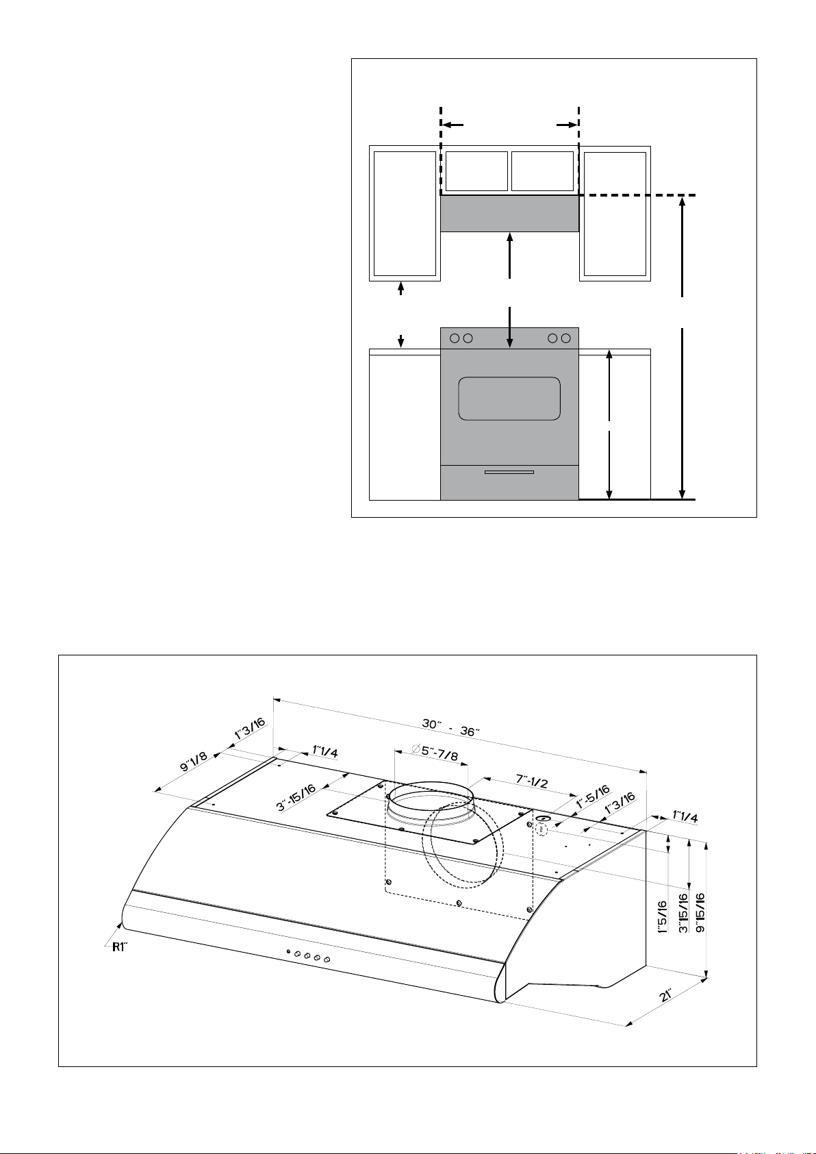
24” minimum
30” suggested maximum
bottom of hood to cooking surface
18” minimum
clearance upper
cabinet to
countertop
36”
70 5/16” minimum
76
5/16” maximum
to bottom of cabinet frame
24” or 30” or 36”
cabinet opening width
INSTALLATION CLEARANCES
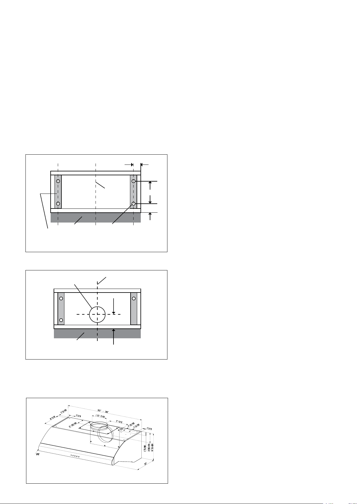
PRODUCT DIMENSIONS
• Recirculating Kit (4" tall recirculation grill + charcoal lter)
- part# DUCTGRT30 for Pellicano 30"
- part# DUCTGRT36 for Pellicano 36"
For best results, use no more than three 90°
elbows. Make sure that there is a minimum
of 24" of straight duct between elbows if more
than one is used. Do not install two elbows
together. If you must elbow right away, do it
as far away from the hood's exhaust opening
as possible.
FIGURE 5
FIGURE 4
CALCULATE THE DUCTRUN LENGTH
FIGURE 4
FIGURE 5
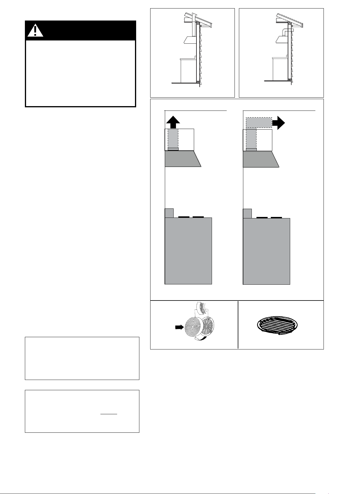
PLAN THE DUCTWORK
FIGURES 1 and 2
FIGURE 3
-
WARNING!
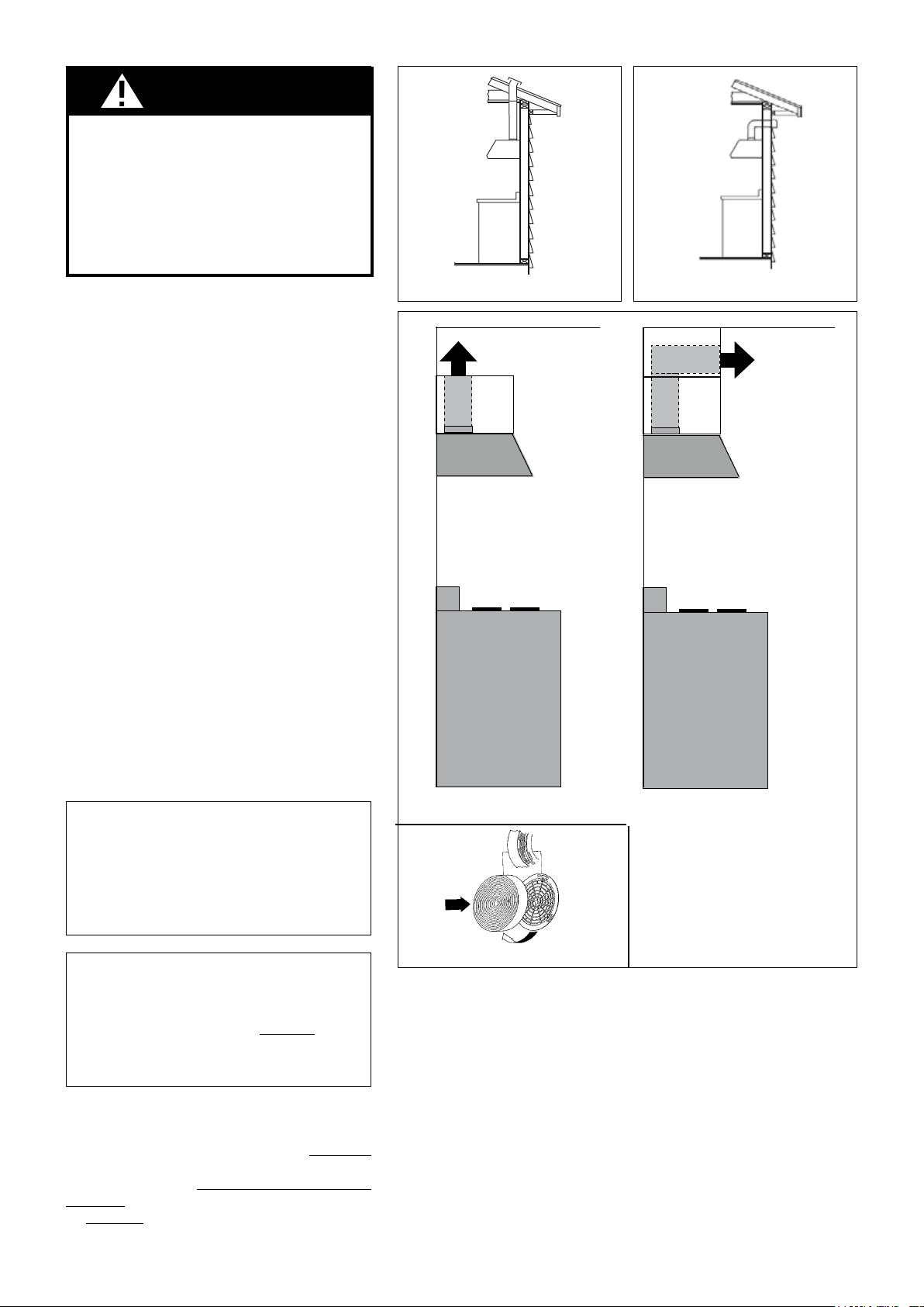
FIGURE 1 FIGURE 2
ceiling
enclosed soffit
side view
rangehood
cooking surface
upper
cabinet
ceiling
open space
side view
rangehood
cooking surface
upper
cabinet
FIGURE 3A FIGURE 3B
FIGURE 3C
WARNING
!
RECIRCULATING INSTALLATIONS
For recirculating installations, Charcoal Filters are necessary. Remove all
grease lters and set aside. Attach one charcoal lter to each end of the
blower. Each charcoal lter attaches to the black grid on the side of the
blower. Rotate the lter clockwise to install and counterclockwise to remove
(FIGURE 3C). Replace all grease lters.
There are 2 ways to recirculate the Pellicano :
1)Use the Recirculation Kit (sold seperately), refer to installation instructions
inside the Recirculation Kit.
2)Some ductwork must be installed to exhaust the rangehood back into the
kitchen, either at the top of the cabinet (FIGURE 3A) or at the face or side
of the soft (FIGURE 3B). Install at least 15" of metal ducting (g. 3A and
3B) at the air exit. Run the duct vertically and secure it at the opening cut
out at the top or side of the cabinet or soft. Installation of a metal grill is
recommended. This duct work must not terminate into a dead air space.
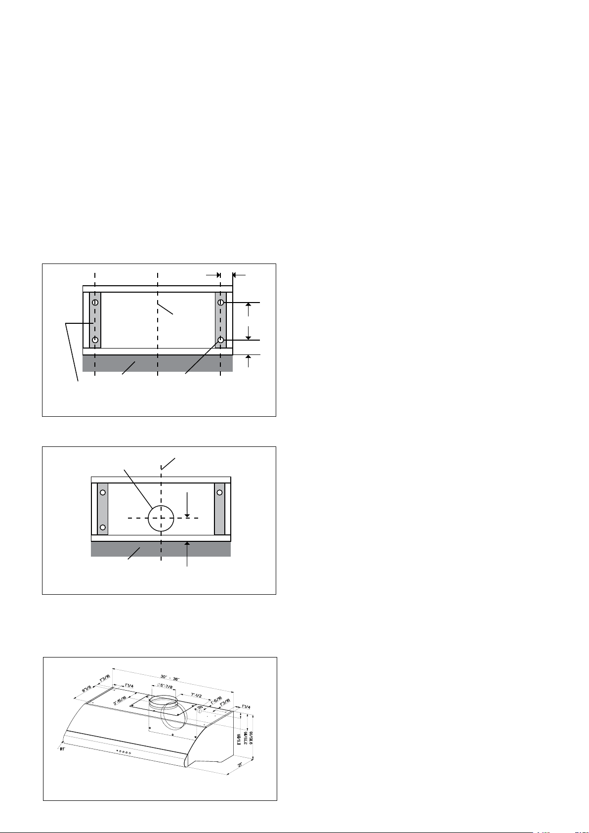
PREPARE THE CABINET
1.
2.
3.
4.
5.
FIGURE 6
7.
FIGURE 7
FIGURE 8
8.
9.
10. -
-
INSTALL THE RANGEHOOD
1.
2.
3.
4.
5.
6.
7.
6
centerline
wall
3 15/16”
6 1/2” diameter hole
centerline
wall
wood filler strips
(recessed cabinet
bottoms only)
3/16”
clearance
holes
9 1/8”
1 3/16”
1 1/4”
Version 07/11 - Page 7
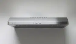
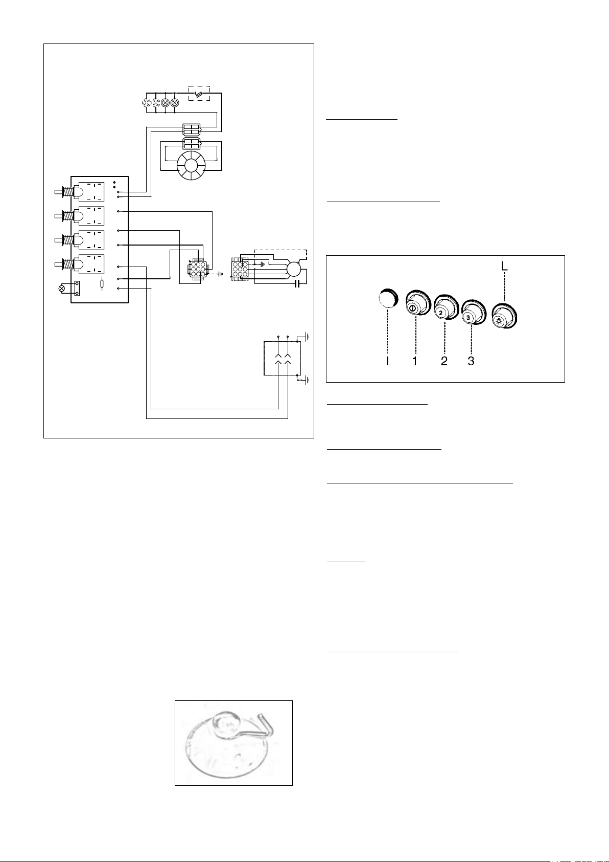
Rangehood Control Panel
in FIGURE 9
Light On/Off Button ( L )
Blower Indicator Light ( I )
Blower On/Off and Speed Buttons ( 1, 2, 3 )
Cleaning
Replacing the Halogen Lamps
FIGURE 10
WIRING DIAGRAM
FIGURE 9
USE AND CARE INFORMATION
For Best Results
0 1 2 3 4 5 6 7 8 9
Creato da.
Rev :
Ver :
DOLCE CORRADO
Materiali: non deveno contenere Pb, Cr6+, Hg, PBB, pbde, ai sensi della direttiva 2002/95 CE
SCHEMA ELETT.M8-4V 3V PULS.SALD. FAR. UL
Non rilevare quote dal grafico non apportare modifiche senza l'autorizzazione d'ufficio p rogettazione
a termini di legge ci riserviamo la pro prieta' del presente disegno con divieto di riproduzione totale o parziale
Code :
Disegno N :
Data:
15.Set.2010
436005057
H90_056
BLK
WHT
Y-G
WIRING BOX
WHT
BLK
N
L
Y-G
LINE IN
120Vac
60Hz ~
FABER
R1
SW4
SW3
SW2
SW1
LP1
N
WHT
BLU
A
BLU
123
6 5 4
789
1 2 3
654
987
RED
M8 4V
120V ~
WHT
BRW
BLU
L
BRW
0-1
BLK
ORG
Y-G
GR
GRY
MID
BK/BR
BLK
MAX
WH/O
ORG
V
RED
0-1 LIGHT
R
VLT
TOROIDAL
TRANSFORMER
WHT
4
3
BLK
RED
2
1
BLK
RED
2
1
RED
VLT
4
3
VLT
HALOGEN
LAMPS
FUSE
FIGURE 10
FUSE REPLACEMENT (IF NEEDED)

FABER WARRANTY & SERVICE (SAVE FOR YOUR RECORDS)
The Following is not covered by Faber's warranty:
Record Your Information Below:
Serial #: __________________________
Date of Purchase: ______________

OUTILS NÉCESSAIRES À L’INSTALLATION
PIÈCES FOURNIES POUR L’INSTALLATION
PIÈCES NÉCESSAIRES POUR L’INSTALLATION
ACCESSOIRES POUR L’INSTALLATION
• Filtres au Charbon
• Recyclage du kit (4" ; gril de recyclage + ltre de
charbon de bois grands)
- partie# DUCTGRT30 for Pellicano 30"
- partie# DUCTGRT36 for Pellicano 36"
24” minimum
30” maximum
distance suggérée entre
le bas de la hotte et
la table de cuisson
18” minimum
distance entre le
placard mural et
le plan de travail
36”
70 5/16” minimum
76
5/16” maximum
jusquʼau
bas du cadre
du placard
24” ou 30” ou 36”
largeur de
lʼouverture du placard
DÉGAGEMENTS DE SÉPARATION À RESPECTER
DIMENSIONS DU PRODUIT
Version 07/11 - Page 10
PLAN DU CONDUIT
-
FIGURES 1 et 2
AVERTISSEMENT!
FIGURE 4
FIGURE 5
CALCUL DE LONGUEUR DU CONDUIT
FIGURE 4
FIGURE 5
Pour de meilleurs résultats, ne pas utiliser plus
de trois coudes de 90
o
. S’assurer qu’il y ait un
minimum de 24 po de conduit droit entre les
coudes si l’on utilise plus d’un coude. Ne pas
installer deux coudes ensemble.
INSTALLATION POUR RECIRCULATION D'AIR
FIGURE 1 FIGURE 2
plafond
soffit inclus
vue de côté
hotte
cuisine de la surface
lʼarmoire
plafond
lʼespace ouvert
vue de côté
hotte
cuisine de la surface
lʼarmoire
FIGURE 3A FIGURE 3B
FIGURE 3C FIGURE 3D
AVERTISSEMENT
!
Pour recycler des installations, les ltres de charbon de bois sont nécessaires.
Enlevez tous les ltres de graisse et les mettez de côté. Attachez un ltre de
charbon de bois à chaque extrémité du ventilateur. Attachés de chaque ltre
de charbon de bois à la grille noire du côté du ventilateur. Tournez le ltre
dans le sens des aiguilles d'une montre pour installer et pour enlever dans
le sens contraire des aiguilles d'une montre (FIGURE 3C). Remplacez tous
les ltres de graisse. Il y a 2 manières de recycler le Pellicano : 1) Employez
le kit de recyclage (vendu séparément), référez-vous aux instructions
d'installation à l'intérieur du kit de recyclage. 2) De la canalisation doit être
installée pour épuiser le rangehood de nouveau dans la cuisine, au dessus
du coffret (FIGURE 3A) ou au visage ou au côté du softe (FIGURE 3B).
Installez au moins 15" ; de la canalisation en métal (g. 3A et 3B) à la sortie
d'air. Courez le conduit verticalement et xez-le à l'ouverture coupée au
dessus ou au côté du coffret ou du softe. L'installation d'un gril en métal
est recommandée. Ce travail de conduit ne doit pas se terminer dans un
espace aérien mort.
Version 07/11 - Page 11
PRÉPARATION DE L'ARMOIRE
1.
2.
3.
4.
5.
FIGURE 6
6
7.
FIGURE 7
FIGURE 8
8.
9.
10.
INSTALLATION DE LA HOTTE
1.
2.
3.
4.
-
5.
6.
7. -
centerline
wall
3 15/16”
6 1/2” diameter hole
centerline
wall
wood filler strips
(recessed cabinet
bottoms only)
3/16”
clearance
holes
9 1/8”
1 3/16”
1 1/4”
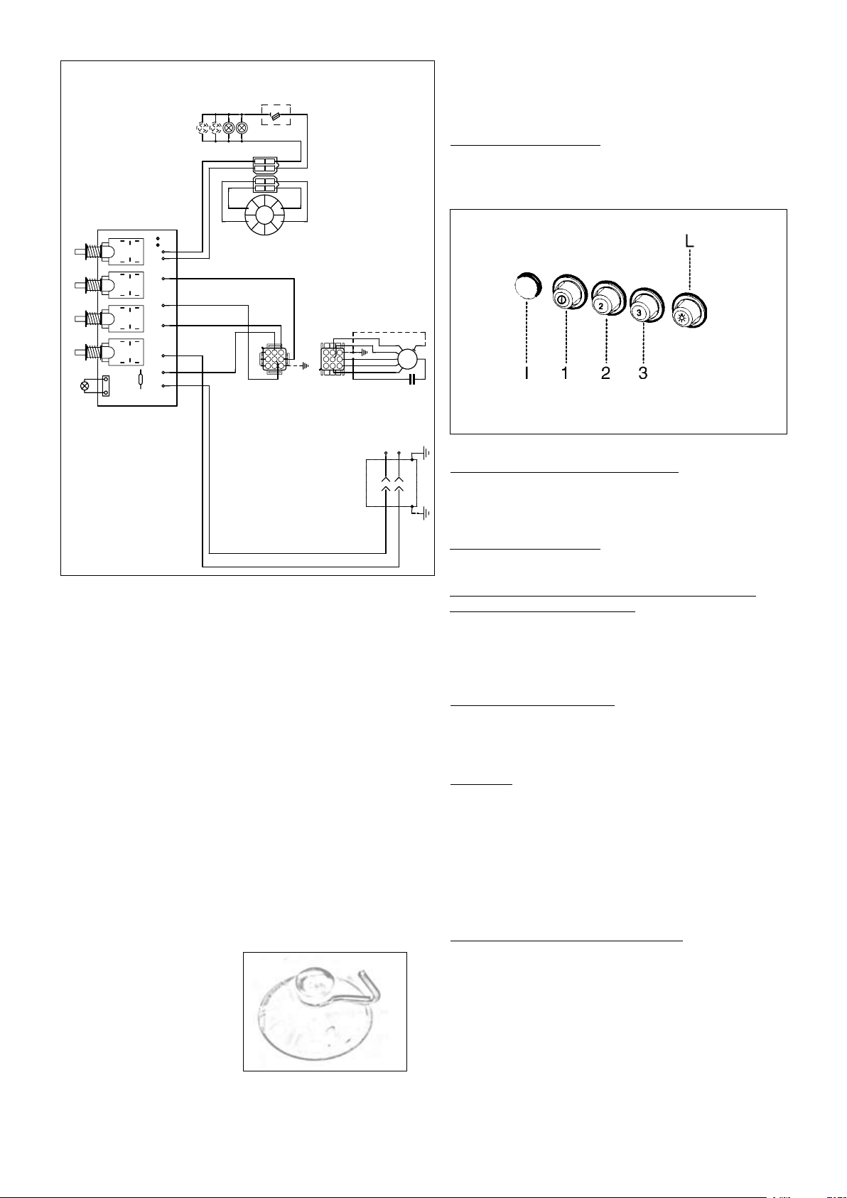
DIAGRAMME DE CÂBLAGE
FIGURE 9
UTILISATION ET ENTRETIEN
Panneau de commandes
FIGURE 9
Bouton marche-arrêt de la lumière (L)
Led allumage moteur ( I )
Bouton marche-arrêt du ventilateur et Boutons de
vitesse du ventilateur ( 1, 2, 3 )
Pour de meilleurs résultats
Nettoyage
Remplacement de la lumière halogène
(de la FIGURE 10)
FIGURE 10
0 1 2 3 4 5 6 7 8 9
Creato da.
Rev :
Ver :
DOLCE CORRADO
Materiali: non deveno contenere Pb, Cr6+, Hg, PBB, pbde, ai sensi della direttiva 2002/95 CE
SCHEMA ELETT.M8-4V 3V PULS.SALD. FAR. UL
Non rilevare quote dal grafico non apportare modifiche senza l'autorizzazione d'ufficio p rogettazione
a termini di legge ci riserviamo la pro prieta' del presente disegno con divieto di riproduzione totale o parziale
Code :
Disegno N :
Data:
15.Set.2010
436005057
H90_056
BLK
WHT
Y-G
WIRING BOX
WHT
BLK
N
L
Y-G
LINE IN
120Vac
60Hz ~
FABER
R1
SW4
SW3
SW2
SW1
LP1
N
WHT
BLU
A
BLU
123
6 5 4
789
1 2 3
654
987
RED
M8 4V
120V ~
WHT
BRW
BLU
L
BRW
0-1
BLK
ORG
Y-G
GR
GRY
MID
BK/BR
BLK
MAX
WH/O
ORG
V
RED
0-1 LIGHT
R
VLT
TOROIDAL
TRANSFORMER
WHT
4
3
BLK
RED
2
1
BLK
RED
2
1
RED
VLT
4
3
VLT
HALOGEN
LAMPS
FUSE
CHANGEMENT DES FUSIBLES

FABER GARANTIE ET SERVICE (
ÉCONOMISER POUR VOS ENREGISTREMENTS
)
Les frais suivants ne sont pas couverts par la garantie Faber :
Enregistrez Votre Information Ci-dessous:
Séquentiel #: __________________________
Date d'achat: ______________