The safe use of this product requires an understanding of the information on the tool and in this operator’s manual as well as a knowledge of the project you are attempting. Before use of this product, familiarize yourself with all operating features and safety rules.
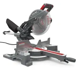
Blade: A 10 in. (254 mm) blade is included with your miter saw. It will cut materials up to 12 in. (304.8 mm) wide, depending upon the angle at which the cut is being made. Carrying Handle: For convenience when carrying or transporting the miter saw from one place to another, a carrying handle has been provided on top of the saw arm. To transport, turn oV and unplug the saw, then lower the saw arm and lock it in the down position by depressing the head lock pin towards the saw housing.
NOTICE: DO NOT perform any cutting operation with the saw in the locked position.
Depth Stop: The depth stop allows the depth of cut of the blade to be limited. The depth stop is useful for applications such as grooving and tall vertical cuts.
Bevel Lock Knob: The bevel lock knob securely locks your compound miter saw at desired bevel angles. two positive stop adjustment screw have been provided on back of the saw.
These adjustment screws are for making łne adjustments at 0° . Miter Lock Handle: The miter lock handle securely locks the saw at desired miter angles. Tighten the handle to lock the saw in place. To release the saw, loosen the handle and squeeze the miter latch lever.
Miter Scale: The miter scale has nine index points provides at 0°, 15°, 22.5°, 31.6°, 45° (left) and 0°, 15°, 22.5°, 31.6°, 45°, 60° (right).
Bevel Scale: The bevel scale has index points provided at 0°, 22.5°, 33.6° and 45° left.
Lower Blade Guard: The lower blade guard is made of shock resistant, see-through plastic that provides protection from each side of the blade. It retracts over the upper blade guard as the saw is lowered into the workpiece.
Slide Bar: When unlocked, the saw arm will glide forward and backward the length of the slide bar for cutting various workpiece widths.
Sliding Fence: The sliding fence provided with this saw help hold the work piece securely when making most cuts. The sliding feature allows for clearance of the saw blade when making bevel or compound cuts. Some cuts may require that the sliding fence be removed completely to avoid interference between the fence and the blade.
Arbor Lock: A arbor lock has been provided for locking the arbor (keeping the saw blade from turning). Depress and hold the lock pin only while installing, changing, or removing the saw blade.
Slide Lock Knob: The slide lock knob locks and unlocks the sliding feature of this tool.
Workpiece Clamp: The workpiece clamp is mounted on the left or right base to securely clamp the workpiece.
Base: Supports the table, holds accessories and allows for workbench or leg set mounting.
Mounting Holes: To mount the miter saw to a stable surface. Trigger Switch: To start the tool, squeeze the trigger. Release the trigger to turn oV the miter saw.
Detent Override: allows the miter table to move freely to any desired angle. With the miter lock handle 1 loosened and the miter latch lever 2 squeezed (step. 1), pull the detent override
3 up (step. 2) and release the miter latch lever 2 (step. 3) to bypass the positive stops on the miter scale. To release the detent override and allow the miter table to engage the
positive stops, squeeze and release the miter latch lever 2 .
Head Lock Pin: Locks the miter saw in the lowered position for storage and transportation.
Switch Handle: The switch handle contains the trigger switch. The blade is lowered into the workpiece by pushing down on the handle. The saw will return to its upright position when the handle is released.
Wrench: One end of the wrench is a hex wrench and the other end is a cross screwdriver. It is used for changing the blade.
The storage area for the wrench is located in the rear of base. Wrench Storage: Convenient storage to prevent misplacing the wrench.
Arbor: The arbor on which a blade is mounted
Arbor Lock: Allows the user to stop the blade from rotating while tightening or loosening the arbor bolt during blade replacement or removal.
Workpiece: The item being cut. The surfaces of a workpiece are commonly referred to as faces, ends and edges.
Table Insert: A plate inserted in the miter saw’s table that allows for blade clearance.
Non-through Cut: Any cutting operation where the blade does not extend completely through the thickness of the workpiece.
Through Sawing: Any cutting operation where the blade extends completely through the thickness of the workpiece. Bevel Cut: A cutting operation made with the blade at any angle other than 90° to the table surface.
Miter Cut: A cutting operation made with the work piece at any angle other than 90° to the blade.
Compound Cut: A crosscut made with both a miter angle and a bevel angle.
Freehand: Performing a cut without the workpiece being guided by a fence, miter gauge, or other aid.
LOOSE PARTS
The following items are included with your miter saw:
ASSEMBLY
Unpacking your miter saw
This product requires assembly.
•Carefully lift saw from the carton by the carrying handle located at the top of the saw body, and place it on a level work surface.
CAUTION: This tool is heavy. To avoid back injury, lift with your legs, not your back, and get help when needed.
•This saw has been shipped with the miter table 60° right & saw head 0° and the saw head secured in the down position.
•To release the saw head, push down the switch handle and pull out the head lock pin.
•Raise the saw head by the handle. Hand pressure should remain on the switch handle to prevent sudden rise upon release of the head lock pin.
•Inspect the tool carefully to make sure that no breakage or damage occurred during shipping.
•Do not discard the packing material until you have carefully inspected and satisfactorily operated the tool.
•The saw is factory set for accurate cutting. After assembling it, check for accuracy. If shipping has influenced the settings, refer to specific procedures explained in this Operator’s Manual.
•If any part is missing or damaged, do not attempt to assemble the miter saw, plug in the power cord, or turn the switch ON until the missing or damaged part is obtained and is installed correctly.
WARNING: The use of attachments or accessories not listed in this manual might be hazardous and could cause serious personal injury.
WARNING: Do not attempt to modify this tool or create accessories not recommended for use with this tool. Any such alteration or modiłcation is misuse, and could result in a hazardous condition leading to possible serious personal injury.
WARNING: Do not connect to the power supply until assembly is complete. Failure to comply could result in accidental starting and possible serious personal injury.
WARNING: Do not start the miter saw without checking for interference between the saw blade and the sliding fences. Damage could result to the blade if it strikes the sliding fence during operation of the saw.
WARNING: This saw can tip over if the saw head is released suddenly and the saw is not secured to a work surface. Always make sure the miter saw is securely mounted to a workbench or approved workstand. Failure to heed this warning can result in serious personal injury.
WARNING: Many of the illustrations in this manual show only portions of the miter saw. This is intentional so that we can clearly show points being made in the illustrations. Never operate the saw without all guards securely in place and in good operating condition.
Unlocking and locking the saw head (Fig. 5a-5c)
Unlocking the saw head:
•To raise the saw head from its storage transport position.
•Firmly grasp the switch handle and apply downward pressure while at the same time pulling the head lock pin 1 .
•Slowly raise the saw head to the up position.
Locking the saw head:
When transporting or storing the miter saw, the saw head should always be locked in the down position.
•Firmly grasp the switch handle and push the saw head down to its lowest position.
•Push the head lock pin 1 into the locking hole and check that the head lock knob is locked in place by turning the knob clockwise.
CAUTION: To avoid injury and damage to the saw, transport and store the miter saw with the saw head locked in the down position. Never use the head lock pin to hold the saw head in a down position for cutting operations.
NOTICE: To avoid damage, never carry the miter saw by the blade guard, power cord, miter lock handle or saw head. ALWAYS use the designated carrying handle 2 located on the top of the saw body or the hand holds 3 on each side underneath of the base (Fig. 4b)
•Loosen the miter lock handle 4 by turning it counter- clockwise and squeeze the miter latch lever 5 , move the table to 0°, release the miter latch lever 5 tighten the miter lock handle 4 .
Mounting the miter saw (Fig. 6a-6c)
WARNING: To avoid injury from unexpected saw movement:
•Disconnect the power cord from the outlet and lock the saw head in the lower position using the head lock pin.
•Lock the slide bars in place by tightening slide lock knob.
•To avoid back injury, lift the saw by using designated carrying handle located on the top of the saw head or the hand holds on each side underneath of the base.
•Never carry the miter saw by the blade guard, power cord, miter lock hand or saw arm. Carrying the tool by the plug cable could cause damage to the insulation or wire connections resulting in electric shock or łre.
•To avoid injury from flying debris, do not allow visitors to stand near the saw during any cutting operations.
WARNING: Before starting any cutting operation, clamp or bolt your miter saw to a workbench or an approved miter saw stand. If a miter saw stand is used, read operator’s manual and follow the instructions for the miter saw stand. Never operate your miter saw on the łoor or in a crouched position. Failure to heed this warning can result in serious personal injury.
Mounting instructions (Fig. 6a-6b):
•For stationary use, place the saw in the desired location, directly on a workbench where there is room for handling and proper support of the workpiece. The base of the saw has four mounting holes 1 (Fig. 6a). Bolt the base of the miter saw to the work surface, using the recommended fastening method as shown in Fig. 6b.
NOTICE: Mounting hardware is not included with this tool. Bolts, nuts, washers and screws must be purchased separately.
For portable use (Fig. 6a, 6c):
•Place the saw on a 3/4" (19 mm) thick piece of plywood 2 (Fig. 6c). Bolt the base of the miter saw securely to the plywood using the mounting holes 1 (Fig. 6a) on the base. Use C-clamps (not included) to clamp this mounting board to a stable work surface at the worksite. (Fig. 6c)
WARNING: Carefully check the workbench or stand after mounting to make sure that no movement can occur during use. If any tipping, sliding, or walking is noted, secure the workbench or stand to the łoor before operating.
Adjusting leveling foot (Fig. 7)
NOTICE: For stabilizing the tool the height of leveling foot 1 can be adjusted. Turn the leveling foot 1 clockwise or counterclockwise depending on the amount of support needed for making sliding cuts.
NOTICE: Many of the illustrations in this manual show only portions of the compound miter saw. This is intentional so that we can clearly show points being made in the illustrations. Never operate the saw without all guards securely in place and in good operating condition.
Install the workpiece clamp (Fig. 8)
NOTICE: There are two mounting holes for the workpiece clamp. These are located just behind the miter fence on the left and right side of the base.
The workpiece clamp provides greater control by clamping the workpiece to the miter table. It also helps to prevent the workpiece from creeping toward the saw blade. This is very helpful when cutting compound miters. Depending on the cutting operation and the size of the workpiece, it may be necessary to use a C-clamp (not included) instead of the workpiece clamp to secure the workpiece prior to making the cut. The workpiece clamp can be installed and used on either side of the blade
To install the workpiece clamp:
•Place the workpiece clamp shaft 1 in one of the holes 2 located behind the miter fence.
•Rotate the workpiece clamp knob 3 to move it up or down as needed to secure the workpiece.
WARNING: In some operations, the workpiece clamp assembly may interfere with the operation of the blade guard assembly. Always make sure there is no interference with the blade guard prior to beginning any cutting operation to reduce the risk of serious personal injury.
Install the dust bag (Fig. 9)
A dust bag 1 is provided for use on this miter saw. It ts over the dust outlet 2 on the back of the saw
NOTICE: The dust outlet also accepts 11/2 " (38.1 mm) vacuum hose.
WARNING: Do not use this saw to cut and/or sand metals. The hot chips or sparks may ignite sawdust from the bag material.
Wrench (Fig. 10)
A wrench 1 is included with this saw. One end of the wrench 1 is a phillips screwdriver and the other end is a hex key. Use the hex key end when installing or removing blade and the phillips end when removing or loosening screws. A storage area 2 for the wrench is located on the left back of the miter saw base.
Remove and install sliding fence (Fig. 11)
Remove sliding fence:
• Loosen the fence lock knob 1 counter-clockwise.
• Slide the sliding fence 2 to the end of the slot and remove it from the slot.
Install sliding fence:
• Loosen the fence lock knob 1 counter-clockwise.
• Insert the sliding fence 2 into the slot and slide the fence to the desired position.
• Tighten the fence lock knob 1.
Unlocking the slide bar (Fig. 12)
• Loosen the slide lock knob 1 counterclockwise, then push the slide bar 2 forward or backward. The slide bar should always be locked in position by tightening it clockwise when transporting or storing.
• The slide lock knob 1 is located on the right of the bevel arm.
Remove and install the table insert (Fig. 13)
To remove / install:
• Unplug the saw.
• Loosen and remove the six screws 1 securing the table insert 2.
• Lift the table insert 2 from the saw.
• To reinstall the table insert 2, reposition the left and right side inserts on either side of the cut line, replace the six screws 1 and tighten, being careful not to overtighten which can cause the table insert to bow or bend.
• Check for blade clearance by moving the slide bar through full motion the blade in table slot. If either side of the table insert hits the saw blade, loosen the three screws for that side and adjust. Tighten the screws and check again for blade clearance.
Removing and installing the blade (Fig. 14a-14c)
WARNING: Only use a 10" (254 mm) diameter blade. Never use a blade that is too thick to allow the outer flange to engage with the flats on the arbor. Larger blades will come in contact with the blade guards, while thicker blades will prevent the arbor bolt from securing the blade on the arbor. Either of these situations could result in a serious accident and can cause serious personal injury. To avoid injury from an accidental start, make sure the switch is in the OFF position and the plug is not connected to the power source outlet.
WARNING: Make sure the arbor lock is not engaged before reconnecting saw to power source. Never engage arbor lock when blade is rotating
• Unplug the saw.
• Raise the lower blade guard 1 out of the way and hold it up.
• Loosen the screw 2 until it disengages the guard plate 3.
NOTICE: Do not remove the screw .
•Swing the guard plate 3 up and out of the way. (Fig. 14a)
•Press in the arbor lock 4 on the back of the saw’s head and hold it in. (Fig. 14b)
•Loosen the arbor bolt 5 with wrench 6 (supplied), Remove the arbor bolt 5 , flat washer 7 and outer flange 8 . (Fig. 14c)
NOTICE: The arbor bolt has a left-handed thread and removes by turning clockwise.
NOTICE: Make sure the inner łange 9 stays in place on the arbor 10.
•If replacing a used blade, remove the blade 11 . Install the new blade. Make sure that the blade’s rotation arrow points in the same direction as the rotation arrow on the upper blade guard.
•Replace the outer flange 8 , flat washer 7 and arbor bolt 5 . Position the cupped side of the outer flange against the blade. Hold in the arbor lock 4 and use wrench to tighten the arbor bolt by turning it counter-clockwise. Release the arbor lock.
•Rotate the guard plate back into place and secure it with the guard plate screw.
WARNING: Make sure the lower blade guard operates smoothly and properly protects from the blade before using the saw.
WARNING: To avoid injury, never use the saw without the guard plate securely in place. It keeps the arbor bolt from falling out if it accidentally loosens and helps prevent the spinning blade from coming off the saw.
WARNING: Make sure the flanges are clean and properly arranged. Lower the blade into the lower table and check for any contact with the metal base or the miter table.
ADJUSTMENT
CAUTION: Your product's miter cut and bevel cut angles have been preset at the factory but can and will be misaligned by rough handling and transportation. It is essential that your new miter saw be realigned before use. Please adhere to the following resetting instructions.
Squaring the blade to the fence (Fig. 15a-15b)
•Unplug the saw.
•Set the bevel and miter angles to 0°.
•Lower and lock the saw head in the “DOWN” position.
•Removing the sliding fence.
•Place a framing square 1 against the fence 2 and saw blade 3 .
NOTICE: Do not touch the tips of the blade teeth with the square.
•If the blade is not 90° to the fence, loosen the four fence locking bolts 4 with the wrench 5 (supplied).
•Adjust the fence to be 90° to the blade and tighten the four fence locking bolts 4 .
CAUTION: If the saw has not been used recently, recheck blade squareness to the fence and readjust if necessary.
•After fence has aligned, replace the sliding fence, using a scrap piece of wood, make a cut at 90° then check squareness on the piece. Readjust if necessary.
Bevel stop adjustment (Fig. 16a-16c)
WARNING: To avoid injury from an accidental start, make sure the switch is in the OFF position and the plug is not connected to the power source outlet.
90° (0°) Bevel adjustment (Fig. 16a-16b)
•Unplug the saw.
•Set the miter table at 0°.
•Pull out the lock button 1 and loosen bevel lock knob 2 , tilt the cutting arm completely to the right. Tighten the bevel lock knob 2 .
•Pull down the cutting head until the blade just enters the table insert.
•Place a framing square 3 on the miter table 4 and up against the saw blade 5 .
•If the blade is not 90° (0°) square with the miter table, loosen the bevel lock knob 2 , tilt the cutting head completely to the left, loosen two bolts 6 on back of saw with a 5 mm hex key (not supplied).
•Tilt the cutting arm back to the right at 90° (0°) bevel and recheck for alignment.
•Repeat above steps if further adjustment is needed.
•Tighten bevel lock knob 2 and two bolts 6 when alignment is achieved.
90° (0°) Bevel pointer adjustment (Fig. 16c)
•When the blade is exactly 90° (0°) to the table, loosen the bevel indicator screw 7 using the wrench (supplied).
•Adjust bevel indicator 8 to the “0” mark on the bevel scale 9 and retighten the screw.
45° Bevel adjustment
• If the 90° (0°) bevel have been set correctly, you do not need to adjust the 45° bevel.
MAINTENANCE
WARNING: Before performing any adjustment, make sure the tool is unplugged from the power supply.
Failure to heed this warning could result in serious personal injury.
WARNING: When servicing, use only identical replacement parts. Use of any other part can create a hazard or cause product damage.
WARNING: To reduce the risk of serious personal injury, DO NOT touch the sharp points on the blade with łngers or hands while performing any maintenance.
WARNING: Always wear eye protection with side shields marked to comply with ANSI Z87.1 during product operation. If operation is dusty, also wear a dust mask.
General maintenance
WARNING: Do not at any time let brake łuid, gasoline, petroleum-based products, penetrating oils, etc., come in contact with plastic parts. They contain chemicals that can damage, weaken, or destroy plastic.
•All bearings are sealed. They are lubricated for life and need no further maintenance.
•Periodically clean all dust and wood chips from around and under the base and the rotary table. Even though slots are provided to allow debris to pass through, some dust will accumulate.
•The brushes are designed to give you several years of use. If they ever need replacement, return the tool to the nearest service center for repair.
Worklight cleaning
•For the best worklight performance, perform the following maintenance regularly.
•Carefully clean sawdust and debris from worklight lens with a cotton swab.
•DO NOT use solvents of any kind, they may damage the lens.
•Dust build-up can block the worklight and prevent it from accurately indicating the line of cut.
•Follow miter saw’s instruction manual to remove and install blade.
•With blade removed from saw, clean pitch and build-up from blade. Pitch and debris can interfere with the worklight and prevent it from accurately indicating the line of cut.
Dust duct cleaning
Depending on your cutting environment, saw dust can clog the dust duct and may prevent dust from flowing away from the cutting area properly. With the saw unplugged and the saw head raised fully, low pressure air or a large diameter dowel rod can be used to clear the dust out of the dust duct.
TROUBLESHOOTING
WARNING: To avoid injury from an accidental start, turn the switch OFF and always remove the plug from the power source before making any adjustments.
All electrical or mechanical repairs should be done only by qualiłed service technicians. Contact CRAFTSMAN Authorized Service Center.
Consult CRAFTSMAN Authorized Service Center if for any reason the motor will not run.
PROBLEM
CAUSE
SOLUTION
Saw will not start.
•Saw not plugged in.
•Fuse blown or circuit breaker tripped.
•Cord damaged.
•Brushes worn out.
•Plug in saw.
•Replace fuse or reset circuit breaker.
•Have cord replaced by authorized service center.
•Service brushes.
Blade does not come up to speed.
•Extension cord too light or too long.
•Low house current.
•Replace with adequate size cord.
•Contact your electric company.
Saw makes unsatisfactory cuts.
•Dull blade.
•Blade mounted backwards.
•Gum or pitch on blade.
•
•
•Incorrect blade for work being done.
•Replace blade.
•Turn blade around.
•Remove blade and clean with coarse steel wool and turpentine or household oven cleaner.