Owner’s Manual
4” Submersible Pumps
Two & Three Wire, 1/2 through 1-1/2 HP
Pump Selection . . . . . . . . . . . . . . . . . 2-3
General Safety . . . . . . . . . . . . . . . . . . . . 4
Electrical . . . . . . . . . . . . . . . . . . . . . . . 5-6
Installation . . . . . . . . . . . . . . . . . . . . . 7 - 9
Troubleshooting . . . . . . . . . . . . . . . . . . .10
Repair Parts . . . . . . . . . . . . . . . . . . . . . .11
Warranty . . . . . . . . . . . . . . . . . . . . . . . . 12
TABLE OF CONTENTS

2
Important Safety Instructions
Carefully read and follow all safety
instructions in this manual and on pump.
SAVE THESE INSTRUCTIONS – This manual
contains important instructions that should be
followed during installation, operation, and main-
tenance of the product. Save this manual for
future reference.
Safety Labels
This is the safety alert symbol. When you
see this symbol on your pump or in this manual,
look for one of the following signal words and be
alert to the potential for personal injury!
Indicates a hazard which, if
not avoided, will result in death or serious injury.
Indicates a hazard which,
if not avoided, could result in death or serious
injury.
Indicates a hazard which, if
not avoided, could result in minor or moderate
injury.
NOTICE indicates practices not related to
personal injury.
Keep safety labels in good condition. Replace
missing or damaged safety labels.
Under certain conditions,
submersible pumps can
develop extremely high
pressure. Install a pressure relief valve capable of
passing entire pump ow at 100 PSI (690 kPa).
Do not allow pump, pressure
tank, piping or any other
system component containing water to freeze.
Freezing may damage system, leading to injury
or ooding. Allowing pump or system compo-
nents to freeze will void warranty.
Can shock, burn or cause
death. To avoid dangerous
or fatal electric shock
hazard, use pump only in a
water well.
Do not install this pump in a pond, river or
other open body of water that could be used
for swimming or recreation. Do not swim,
wade or play in a body of water in which a
submersible pump has been installed.
Install ground and wire
pump according to local
and Canadian Electrical Code or National
Electrical Code requirements that apply.
Disconnect electrical
power supply before
installing or servicing pump.
Make sure line voltage
matches pump voltage
and frequency.
Install pump according to all plumbing, pump
and well code requirements.
Test well water for purity before using well.
Call your local health department for testing
procedure.
During installation, keep well covered to pre-
vent leaves and foreign material from falling
into the well. Foreign objects in well can con-
taminate water and cause serious mechani-
cal damage to pump.
Pipe joint compound can cause cracking in
plastics. Use only Teon tape when sealing
joints in plastic pipe or connecting pipe to
thermoplastic pumps.
HAZARDOUS
HAZARDOUS
VOLTAGE
GENERAL SAFETY

3
Selecting the Correct Pump
Before you remove and reinstall your submersible well pump, let’s review
your well condition and the pumps capabilities.
WELL LOG INFORMATION
The driller that drilled your well should have given you a ‘well log’
summarizing the:
A. Depth that the well was drilled, ie 170 ft. from the surface.
B. Depth to what level the water rose in well, ie 130 ft. from the
surface
C. Depth to what level the water dropped to with the test pump
pumping in your well, ie dropped 20’ to 150’ from the surface
when pumping continuously
D. The gallons per minute your pump pumped, ie 10 GPM
In some counties this information is recorded at the health oce or other
oces of the county and/or the driller may have retained the information in
the driller’s le.
You need a copy of the well log or this information from the well log.
If you can not nd the well log, you will need to drop a weighted string in
the well to:
A. Record the depth when it hits the bottom of the well.
B. The depth at which water is standing in the well, ie the length of
string from the weighted end of the string that is wet.
NOTE, your pump needs to be installed at minimum 5’ above the bottom of
the well and 15-20’ below the surface of the water column in the well.
STOP
Before you start

4
4” PUMP DESIGN AND OPTIMUM PERFORMANCE
VOLTAGE
NUMBER OF PUMP WIRES AND CONTROL BOXES
CONFIRMATION OF SELECTION
This pump is designed to pump 10 gallons per minute (10
GPM), which is the average size home’s (3-4 bedroom)
use of water per minute. Larger homes will require larger
pumps.
4” pumps are oered in either 2-wire or 3-wire, indicating
the number of wires running from the pump motor.
2-wire motors have 3 wires running from the motor, 2 to
provide electric service and 1 ground wire. The motor
controls are in the motor in the well.
3-wire motors have 4 wires running from the motor, 3 to
provide electric service and 1 ground wire. These motors
require a motor control box mounted on the wall near your
water pressure tank.
2-wire motors are typically only used in wells less than
300’ depths and 3-wire motors can be used in wells at any
depth.
Some users prefer their motor controls be readily available
for service. A 3-wire pump with control box mounted near
the tank provides ease of serviceability.
Knowing the above and prior to installing or removing and
reinstalling your 4” pump, please conrm the following:
• The correct HP for the depth the pump will be in the well.
• The correct GPM (gallons per minute) for your
application.
• The correct voltage
• The correct number of wires
• The correct control box (if applicable)
3-wire start components including capacitors and relays
are located in the control box for ease of service. 2-wire
start components are inside the hermetically sealed pump
motor and rarely fail. If failure does occur, the pump must
be replaced.
NOTE: Control box voltage and horsepower must match
pump voltage and horsepower.
PUMP CONTROL BOX
HP VOLTAGE HP VOLTAGE
1/2 115 1/2 115
1/2 230 1/2 230
3/4 230 3/4 230
1 230 1 230
1-1/2 230 1-1/2 230
4” submersible pumps are oered in two voltages, 115 or 230V. Be sure
you select a pump whose motor voltage matches the voltage at the well
Deeper wells require higher horsepower to deliver water
to the home. See chart at right to ensure you have chosen
the correct horsepower for your application.
PROPER 4” PUMP SELECTION
HP GPM PUMP DEPTH IN WELL
1/2 10 60-100’
3/4 10 100-175’
1 10 175-250’
1-1/2 10 greater than 250’
PRE-INSTALLATION

Can shock, burn or cause
death. Permanently ground
pump, motor and
submersible motor control
before connecting power supply to motor.
5
Ground submersible motor in accordance with all codes
and ordinances that apply. Use copper ground wire at
least as large as wires carrying current to motor.
Motor is supplied with copper ground wire. Splice to cop-
per conductor that matches motor wire size specied in
Table 3. See “cable splicing” under installation.
Permanently ground pump, motor and submersible motor
control before connecting power cable to power supply.
Connect ground wire to approved ground rst, then con-
nect equipment being installed.
Do not ground to a gas supply line.
PLANNING INSTALLATION
Inspect the pump and motor for delivery damage. Report
any damage immediately to the shipping carrier or to your
dealer.
The well driller should pump out all ne sand and foreign
matter before the pump is installed. See the Initial Start-
Up section of this manual.
Pump performance is based on pumping clear, cold, liquid
water with no entrained air. Warranty is void in the follow-
ing conditions:
• If the pump has pumped excessive sand - excessive
sand can cause premature wear to pump.
GROUNDING THE PUMP
• If water is corrosive
• If entrained gas or air are present in water being
pumped - these can reduce ow and cause cavitation
which can damage pump.
• If pump has been operated with discharge valve
closed - severe internal damage will result.
Install the pump at least 15 to 20 ft. (4.5 to 6 m) below the
lowest water level reached with the pump running (lowest
draw-down water level), and at least 5 ft. (1.5M) above the
bottom of the well.
To avoid over-heating wire and excessive voltage drop at
motor, be sure wire size is sucient per NEC standards for
the pump horsepower and length of wire run.
NOTICE: See installation Wiring Diagrams for typical wiring
hookups and submersible motor control identication.
PRE-INSTALLATION
WIRING CONNECTIONS
All wiring must meet National Electrical Code or Canadian
Electrical Code and local code requirements.
Use only copper wire for connections to pump and sub-
mersible motor control.
Table 1: Recommended Fusing Data -
60 Hz, Single Phase, 3 Wire Submersible Pump Motors
Table 2: Recommended Fusing Data -
60 Hz, Single Phase, 2 Wire Submersible Pump Motors
Fuse Size
HP Volts Standard Dual Element
1/2 230 20 10
3/4 230 25 15
1 230 30 20
1-1/2 230 35 20
Fuse Size
HP Volts Standard Dual Element
1/2 115 35 20
3/4 230 20 10
1 230 25 15
1-1/2 230 30 20
HAZARDOUS
PRESSURE
Risk of shock or re. Can shock, burn or kill. Permanently ground the pump,
motor and control box before connecting the power supply to the motor.

WIRING CONNECTIONS
6
Ensure the ground control box, all metal plumbing and
motor frame with copper wire are in compliance with local
codes. Use a ground wire at least as large as the wires
supplying power to the motor.
Permanently close all unused openings in this and other
equipment.
Disconnect power to the control box before working on or
around the control box, pipes, cable or pump.
INSTALLATION WIRING - SINGLE PHASE, 3 WIRE
For motors of 1-1/2 HP and above, use a magnetic starter to avoid damage to
the pressure switch. Consult factory for wiring information.
Risk of electric shock. Can shock, burn or kill.
Copper Cable Length in Ft. (Service to Motor) G-Series Motors: 1 Ph, 2-Wire Cable, 60 Hz. Wire Size
Copper Cable Length in Ft. (Service to Motor) G-Series Motors: 1 Ph, 3-Wire Cable, 60 Hz. Wire Size
HP Volt Wire Size, AWG
14 12 10 8 6 4 3 2 1 0 00
0.5 115
0.5 230 466 742 1183 1874 2915 4648 5843 7379 9295 11733
0.75 230 353 562 891 1420 2210 3523 4429 5594 7046 8895 11222
1 230 271 430 686 1087 1692 2697 3390 4281 5394 6808 8590
HP Volt Wire Size, AWG
14 12 10 8 6 4 3 2 1 0 00
0.5 230 359 571 912 1444 2246 3581 4502 5685 7162 9040
0.75 230 281 447 713 1129 1757 2800 3521 4446 5601 7070 8920
1 230 233 371 592 937 1458 2324 2921 3689 4648 5867 7402
All cable lengths meet NEC for jacketed 60ºC copper cable. Based on 3-Wire Induction Run requirements; Capacitor
Run requirements may vary. Local code requirements may vary. For aluminuncable, go up two sizes from chart (for
example, if the chart calls for No. 10AWG (6mm
2
) for copper, go to No. 8 AWG (10mm
2
) for aluminum; the smaller the
number, the larger the cable). Use oxidation inhibitors on the connections.
HP Voltage Motor Number Control Box Number
1/2 115
1/2 230 FM4300531A-01 FM005CB-IR2-01
3/4 230 FM4300731A-01 FM007CB-IR2-01
1 230 FM4301031A-01 FM010CB-IR2-01
Match the motor to the control box as shown below:
INSTALLATION
7
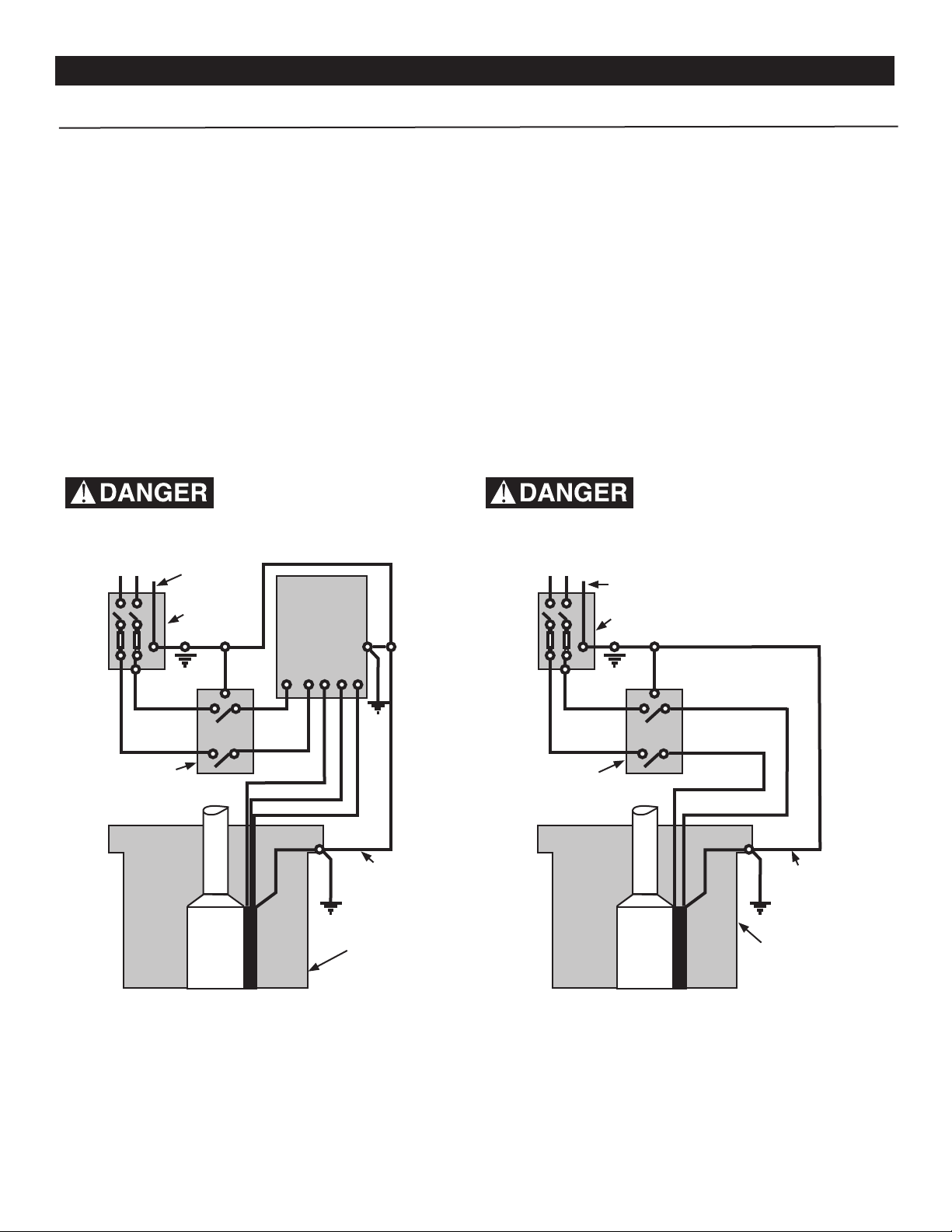
115V or
230V Line
Ground
Ground
Well Casing
Red
Yellow
Black
Fused
Disconnect
Switch
Pressure
Switch
L1 L2 R Y B
L1
L2 M2
M1
{
Submersible
Motor
Control
To Line
Ground
Ground
(Green)
Well Casing
Black
Black
Fused
Disconnect
Switch
Pressure
Switch
L1
L2 M2
M1
{
Three Wire- 1/2 through 2 HP Submersible Motor Con-
trol. Follow color coding when connecting submersible
motor control. (Yellow to Y, Red to R, Black to B)
Figure 1-A Figure 1-B
Two-wire pumps have two power supply wires (Black/
Black) and one ground wire. Submersible motor control
is not required.
Disconnect power before working on or around submers-
ible motor control, pipes, cable, pump or motor.
Ground submersible motor control, all metal plumbing and
motor frame with copper wire in compliance with National
Electrical Code or Canadian Electrical Code and local
code requirements. Use ground wire at least as large as
the wires supplying power to motor.
At well head, connect ground wire to grounding terminal
that meets Canadian Electrical Code or National Electri-
cal Code requirements that apply. For more information,
contact local code ocials.
Permanently close all unused openings in this and other
equipment.
INSTALLATION WIRING INSTRUCTIONS
Single Phase, 3 Wire Installation
Single Phase, 2 Wire Installation
Note:
Install submersible motor control vertically on wall with top
side up. 3-Wire pumps have three power supply wires
(Red/Black/Yellow) and one ground wire (Green)
3 wire pumps will not operate without submersible motor
control; attempting to do so will burn out motor.
Installations must include circuit and component protection
in compliance with U.S. National Electrical Code or
Canadian Electrical Code, Par 1.
If main overload trips, look for:
1. Shorted Capacitor
2. Voltage Problems
3. Overload or locked pump
Hazardous voltage.
Can shock, burn or kill.
Hazardous voltage.
Can shock, burn or kill.
INSTALLATION
8
NOTICE:
Since the tightly wound tape is the only means
of keeping water out of the splice, the eciency of the
splice will depend on the care used in wrapping the tape.
NOTICE: For wire sizes larger than #8, (7mm
2
) use a sol-
dered joint rather than Scotchl putty.
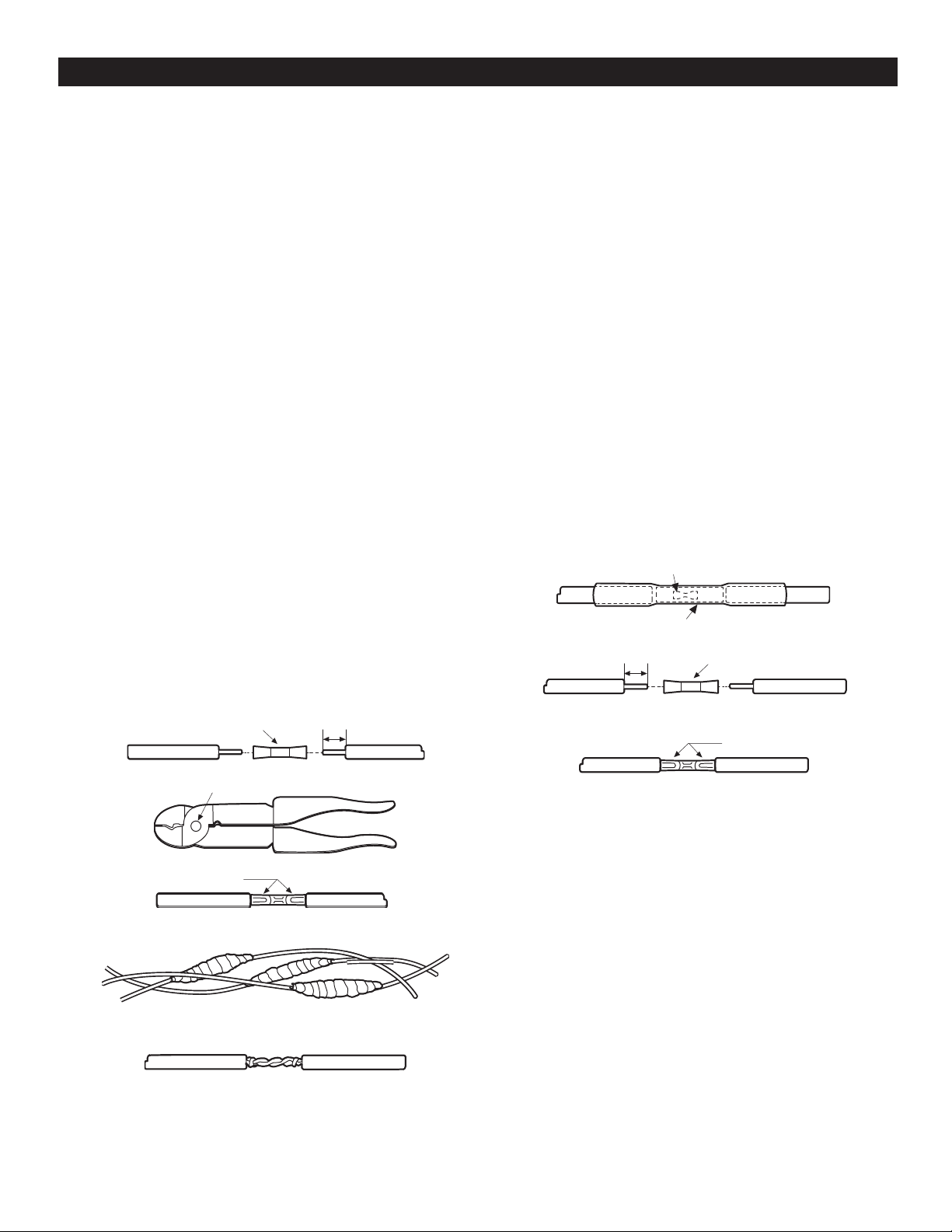
Wire Splicing
Splice wire to motor leads using only copper wire for
connections to pump motor and control box.
1. Tapered splice (Wire sizes No. 8 and larger):
A. Cut motor lead staggering lead and wire length
so that second lead is 2” longer than rst lead and
third lead is 2” longer than second.
B. Cut o power supply wire ends. Match colors and
lengths of the wires to colors and lengths of motor
leads.
C. Trim installation back 1/2” from supply wire and
motor lead ends.
D. Insert motor lead ends and supply wire ends into
butt connectors. Match wire colors between supply
wires and motor leads.
E. Using crimping pliers, indent butt connector lugs to
attach wire.
F. Cut electrical “Scotchl™” or equivalent insulation
putty into three equal parts and form tightly around
butt connectors. Be sure Scotchl™ overlaps
insulted part of wire.
G. Using #33 Scotch™ or equivalent tape, wrap each
joint tightly; cover wire for about 1-1/2” on each
side of joint. Make four passes with the tape. When
nished you should have four layers of tape tightly
wrapped around the wire. Press edges of tape
rmly down against the wire.
NOTICE: Since tightly wound tape is the only
means of keeping water out of splice, eciency of
splice will depend on the care used in wrapping the
tape.
NOTICE: For wire sizes larger than No. 8, use
soldered joint rather than Scotchl™ putty.
2. Heat shrink splice
[for wire sizes #14, 12 and AWG (2,3 and 5mm)]
A. Remove 3/8” insulation from ends of motor leads
and power supply wires.
B. Put plastic heat shrink tubing over motor leads
between power supply and motor.
C. Match wire colors and lengths between power
supply and motor.
D. Insert supply wire and lead ends into butt
connector and crimp. Match wire colors between
power supply and motor. Pull leads to check
connections.
E. Center tubing over butt connector and apply heat
evenly with torch (match or lighter will not supply
enough heat).
NOTICE: Keep torch moving. Too much concen-
trated heat may damage tubing.
3. Mechanical Splice Kit with plastic insulators (for 14, 12
and 10 Gauge AWG Wire (2, 3 and 5mm):
A. Cut motor leads staggering lead and wire length so
that 2nd lead is 4” (101.6mm) longer than 1st lead and
3rd lead is 4” (101.6mm) longer than second.
B. Cut wire ends matching colors and lengths of wires
between power supply and motor.
C. Trim insulation back 1/2” (12.7mm) from power supply
wire and motor lead ends.
D. Unscrew plastic caps from insulators. Place a cap
and neoprene gasket sleeve on each wire to be
spliced.
E. Slide insulator body onto one wire end.
F. Insert wire end into butt connector and crimp.
Match wire colors between power supply and motor
G. Center insulator body over splice and slide gasket
sleeves into body as far as they will go. Screw caps
onto insulator body and tighten by hand for a strong,
waterproof splice.
Notch
1/2” (12.7mm)
1/2” (12.7mm)
Indent here
Connector
Butt Connector
Heat Shrink Tubing
Butt Connector
Indent here
Completed Splice
Alternate Method
twist and solder

INSTALLATION
9
Mechanical Splice Kit with Plastic Insulators
(for 14, 12 and 10 Gauge AWG Wire, or 2, 3 and
5.5mm
2
Wire)
1. Cut o motor leads. Stagger the lead and wire length so
that the second lead is 4 inches (101.6mm) longer than
the rst lead and the third lead is 4 inches
(ioi.6mm) longer than the second.
2. Cut o wire ends. Match colors and lengths of the power
supply wires to colors and lengths of the motor leads.
3. Trim insulation back 1/2” (13mm) from the cable ends
and motor lead ends.
4. Unscrew plastic caps from insulators. Place a cap
and a neoprene gasket sleeve on each wire end to be
spliced. Slide the insulator body onto wire end.
5. Insert the wire end into the butt connector and crimp.
Match cable and motor wire colors.
6. Center the insulator body over splice and slide the
neoprene sleeves into the body as far as they will go.
Screw caps onto the insulator body and tighten by hand
for a strong, waterproof splice.
Insulator Body
Butt Connector or Crimp or Solder
End Cap
Gasket
Gasket Sleeve
in Place
Cap screwed onInsulator
Body
Centered
Over Splice
1/2” 1/2”
12.7mm 12.7mm

INSTALLATIONS
10
Discharge outlet is 1-1/4” FNPT threaded. Use 100 PSI
(689.5kPa) rated polyethylene plastic pipe for installations
up to 100’ (30.5M) depth.
Use 160 PSI (1103.2 kPa) rated polyethylene plastic for
installations up to 220’ (67.1M) depth.
For depths beyond 220’ (67.1M) use galvanized steel
pipe for the entire drop pipe.
INITIAL START-UP/NEW WELLS
NOTICE: NEVER operate pump with gate valve completely
closed. Pump can destroy itself if run with valve shut o
(“dead- headed”) and warranty will be void.
NOTICE:
To avoid sand-locking pump, follow procedure below
when starting pump for the rst time. NEVER start a pump
with gate valve completely open unless you have done this
procedure rst.
1. Connect a pipe elbow, a short length of pipe and a
gate valve to pump discharge at well head (see Fig. 3).
2. Mount submersible motor control (3-wire pump) or
fused disconnect switch (2-wire pump) in a perma
nently weatherproof place. Make sure that controls
will not be subjected to extreme heat or excess
moisture.
3. Make sure controls are in OFF position.
4. Connect motor leads and power supply to
submersible motor control or magnetic starter
(see Installation Wiring Diagrams).
DO NOT START PUMP YET.
5. Set gate valve on discharge 1/3 open; start pump
(see Fig. 3).
6. Keep gate valve at this setting while water pumps
out on ground. Let run until water is clear of sand or
silt. (To check solids in water, ll a glass from pump
and let solids settle out).
7. When water is completely clear at 1/3 setting, open
gate valve to approximately 2/3 open and
repeat process.
8. When water is completely clear at 2/3 setting, open
gate valve completely and run pump until water is
completely clear.
9. Remove gate valve for permanent installation near
tank (Fig. 4).
10. Install sanitary well seal or pitless adapter unit, well
unit, electrical conduit and surface piping. Installa-
tion must meet all code requirements that apply.
.
Pipe joint compound can cause
cracking in plastics. Use only Teon
tape on joints in plastic pipe.
NOTICE:
Allowing pump or piping system to freeze may severely
damage pump and will void warranty. Protect pump and
entire piping system (including pressure tank) from freezing.
Pre-Charged Pressure Tank Hookup
See Fig. 4 for piping connections to pre-charged pressure tank.
NOTICE:
Check air pre-charge in tank before starting pump. Adjust
pre-charge to 2 PSI (13.8kPa) below pump cut-in setting,
(ie, a pre-charge tank used with a 30-50 switch should be
pre-charged with air to 28 PSI (193.1 kPa). Adjust pre-charge
by adding or bleeding air through schrader valve located
on top of tank. Check pre-charge annually and adjust as
needed.
Gate valve
Electrical
disconnect
box
Temporary
wiring to
disconnect
box
Temporary
piping
Pump in well
FIG. 3
Connecting To Tank/Water System
Hazardous pressure. Submersible
pumps can develop very high pressure
in some situations. To prevent tank blowup, install a pressure relief
valve able to pass full pump ow at 100 PSI (690 kPa).
TEMPORARY CONNECTIONS WHILE CLEANING
WELL FOR START-UP
Power Supply Wire Installation
1. To test submersible, momentarily (no more than 5
seconds) connect it to proper power supply. Power
supply frequency and voltage must match motor name
plate frequency and voltage to within ±10%.
2. Fasten power supply wire leads securely to pump
discharge section; leave 4-5” (100-125mm) of slack in
leads at this point. Securely fasten leads to plastic pipe
within 6” (150mm) of the pump discharge section. Use
centering guides to protect wire and pipe from rubbing
well casing.
3. Connect copper ground wire to motor bracket. Ground
wire must be as large as wires supplying current to
motor. Consult current Canadian Electrical Code and
local codes for grounding information.
4. Most 4” pumps have an eyelet on the pumps discharge
for attaching a rope to assist in lowering into and
pulling the pump from the well. Attach a nylon rope of
adequate length to eyelet
5. Do not use submersible power supply wires supplied
by pump manufacturer to lower or lift pump. When
lowering pump into well use only the rope and/or
discharge pipe, secure supply wires to discharge pipe
at 10 ft. (3M) intervals with Scotch™ #33 or equivalent
electrical tape. DO NOT damage pump wires.
NOTICE:
To avoid dropping pump down well or damaging wires
or splices, NEVER allow pump wires to support weight
of pump.

11
(Figure 4)
Typical Pre-Charge Tank Connections
Pre-charged Tank
CUT IN CUT OFF PRE-CHARGE TANK
PSI (kPa) PSI (kPa) PSI (kPa)
20 (137.9) 40 (275.8) 18 (124.2)
30 (206.8) 50 (344.7) 28 (193.1)
40 (275.8) 60 (413.7) 38 (262)
To house
Gate valve
Relief valve Union
Vent well cap
Submersible
power cable
Check valve
Pump
Plastic Pipe
Adapter
Centering
Guide
Pitless
adaptor
Nylon tape
attached to
pipe
Electrical
disconnect
Submersible
motor control
(3 wire models)
Pressure Switch
Pressure Gauge
Important Electrical Grounding Information
Hazardous voltage. Can shock,
burn, or kill. To reduce the risk
of electrical shock during pump operation, ground and
bond the pump and motor as follows:
A. To reduce risk of electrical shock from metal parts of
the assembly other than the pump, bond together all
metal parts accessible at the well head (including
metal discharge pipe, metal well casing, and the
like). Use a metal bonding conductor at least as large
as the power cable conductors running down the
well to the pump’s motor.
B. Clamp or weld (or both if necessary) this bonding
conductor to the grounding means provided with the
pump, which will be the equipment-grounding
terminal, the grounding conductor on the pump
housing, or an equipment-grounding lead. The
equipment-grounding lead, when provided, will be
the conductor having green insulation; it may also
have one or more yellow stripes.
C. Ground the pump, motor, and any metallic conduit
that carries power cable conductors. Ground these
back to the service by connecting a copper
conductor from the pump, motor, and conduit to
the grounding screw provided within the supply-
connection box wiring compartment. This conductor
must be at least as large as the circuit conductors
supplying the pump
SAVE THESE INSTRUCTIONS.
INSTALLATIONS

12
TROUBLE SHOOTING
PROBLEM CHECK CORRECTIVE ACTION
MOTOR WILL NOT START BUT No voltage at submersible motor control or disconnect switch. Replace blown fuses.
FUSES DO NOT BLOW
No voltage at pressure switch. Replace faulty pressure switch.
No voltage at submersible motor control box. Rewire supply to submersible motor control.
Cable or splices bad. Consult licensed electrician or serviceman.
Submersible motor control box incorrectly wired. Reconnect submersible motor control correctly
(see Wiring Installation Diagrams).
FUSES BLOW OR TRIPS Wrong size fuse or wrong time delay fuse. Check fuse size against chart, Page 4. Install correct fuse or
WHEN MOTOR STARTS size time delay fuse.
Wire size too small. Check wire size against chart, Page 4. Install correct size wire.
Starting capacitor defective, or blown Check submersible motor control box to see if starting capacitor
has blown out. Replace starting capacitor.
Voltage is too low or high voltage. Check that line voltage is within ±10% of nameplate. If voltage
variation is greater than ±10%, call power
company or local hydro authority to adjust voltage.
Power supply wire leads not correctly connected to Check submersible motor control wiring diagram against
submersible motor control box. incoming power hookup. Check power supply wire
motor control cover. Reconnect power supply wires so
wire color code matches motor lead color code.
Broken wire in submersible motor control box. Examine all connections and wiring in submersible. Disconnect
power and repair or replace faulty wire.
Pump or motor stuck or binding. Check for locked shaft in pump. If necessary, pull pump (make all
possible above ground checks first). If pump is locked, replace it.
Clean well of all sand or lime before reinstalling pump.
FUSES BLOW OR OVERLOAD The voltage is either too high or too low. Check that line voltage is within ±10% of rated nameplate
PROTECTOR TRIPS WHEN MOTOR voltage while motor is running. If voltage variation is more
IS RUNNING than ±10%, call power voltage while motor is running.
High ambient (atmospheric) temperature is too high. Check temperature of submersible motor control. Do not mount
submersible motor control in direct sunlight.
Submersible motor control with wrong voltage or horsepower rating. Compare voltage and horsepower on motor nameplate
with those given on control box nameplate or on the
circuit diagram inside submersible motor control cover. Replace the
control box if the numbers do not match.
Wire size too small. Check wire size against the table in the wiring section of this
manual. Install the correct size wire.
Cable splices or motor leads grounded, shorted or open. Consult a licensed electrician or qualified serviceman. Do not
attempt to disassemble the pump or motor.
PUMP STARTS TOO FREQUENTLY Leaks in system. Check all tank connections with soapsuds for air leaks. System
must be air and water tight.
The pressure switch is defective. Check for defective switch or switch out of adjustment. Re-adjust
or replace pressure switch.
Tank waterlogged. Pre-charged tanks: check tank pre-charge air pressure and check
for leak in bladder. Adjust air pressure to 2 PSI (13.8kPa)
less than pump cut-in pressure (when there is no water
pressure on system). Replace bladder if necessary.
Air over water tanks: check for air leaks. Check Air Volume Control
(AVC). Check snifter valve operation. Repair or replace tanks;
replace snifter valves if necessary.
Leak in drop pipe. Raise drop pipe one length at a time until water stands in pipe.
Replace the pipe above that point.
Pressure switch too far from tank. Measure distance from pressure switch to tank. Move switch to
within 1’ (.3M) of tank.
LITTLE OR NO WATER DELIVERED The bleeder orifice check valve is stuck or installed backwards Examine valve. If stuck, free valve; if installed backwards, reverse it.
(standard tank only).
Low water level. Determine lowest water level in well while pump is running and
compare to pump depth setting. Lower pump further into well (but
at least 5’ (1.6M) above bottom of well). Throttle pump discharge
until discharge equals recovery rate of well.
NOTICE: Running pump while airlocked can cause loss of
prime and seriously damage pump.
Low voltage. Check voltage at submersible motor control with pump running.
Check incoming wire size and power supply wire size against
the tables in the wiring section of this manual. Install larger wire
from meter to submersible motor control. Install larger wire from
submersible motor control to pump.
If necessary, have power company raise supply voltage.
Plugged intake screen. Pull pump and check condition of screen. Clean or replace as necessary.
Check valve at pump if discharge is stuck. Pull pump and examine check valve. Free check valve.
Impellers and diffusers are worn. Make sure system is clear of obstructions and pump is in solid
water and operating normally.
AIR OR MILKY WATER DISCHARGE Gas in well water. Check for presence of gas in well water. Remove bleeder orifices;
FROM FAUCETS Remove bleeder orifices; plug tees. Be sure plugged tees
do not leak. If necessary, separate gas from air before
it enters pressure tank.
Air volume control not working (standard tanks only) Make sure ports and ball check valves are clear. Replace control if
necessary
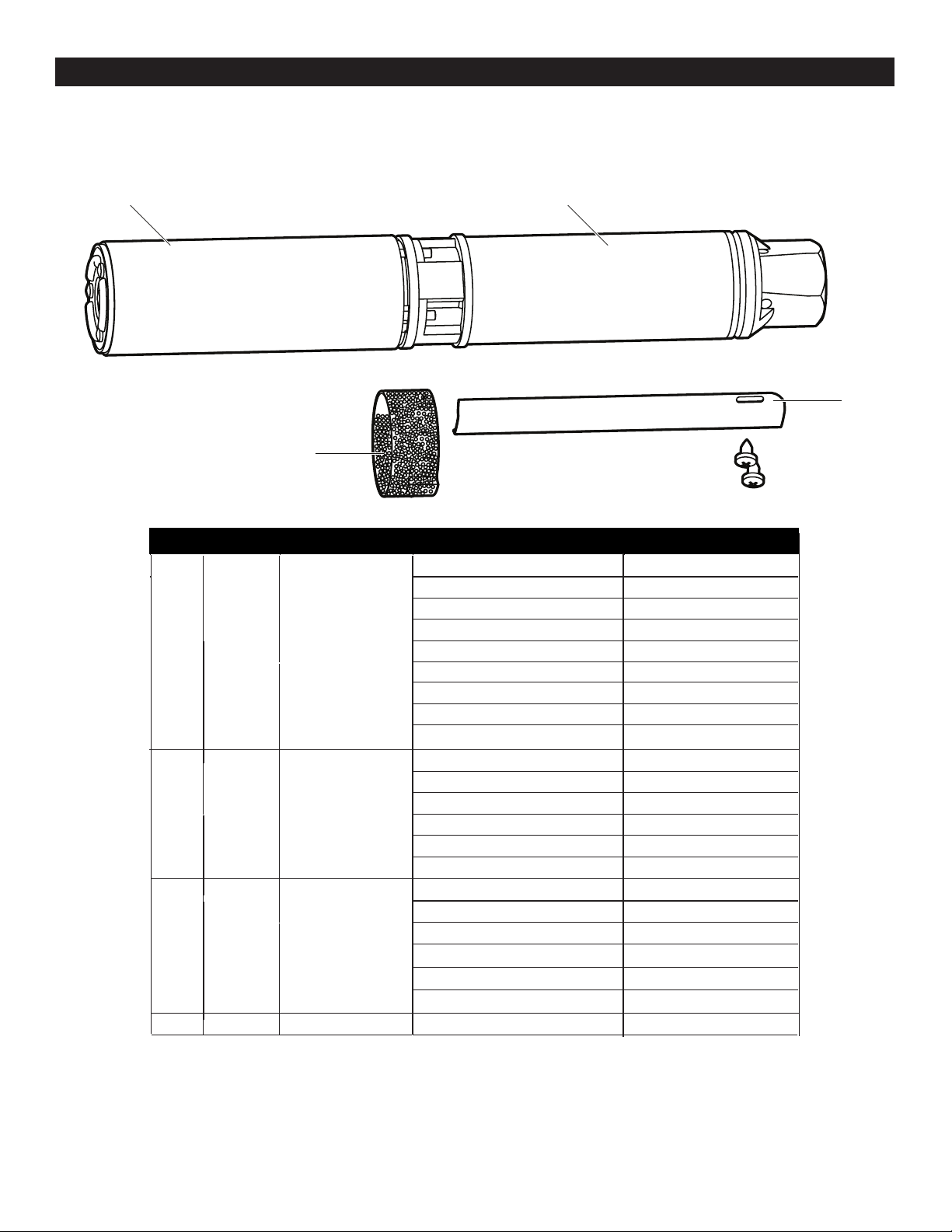
SUBMERSIBLE PUMP REPAIR PARTS
11
1
4
3
2
NO. QUANTITY PART NUMBER DESCRIPTION
PART NAME
1
2
3
4
1 Motor
1/2HP 2W 230V EFSUB0502
1/2HP 3W 230V EFSUB0503
3/4HP 2W 230V EFSUB0751
3/4HP 3W 230V EFSUB0752
1HP 2W 230V EFSUB1001
1HP 3W 230V EFSUB1002
1 Pump End
1/2HP 12GPM EFSUB0506
1HP 25GPM EFSUB1004
1HP 12GPM EFSUB1003
1 Suction Screen EFSUB0509
3/4HP 12GPM EFSUB0753
1 Wire Guard
1/2HP 2W 115V EFSUB0501
1.5HP 3W 230V EFSUB1501
1.5HP 2W 230V EFSUB1502
EFSUB1504
EFSUB1503
1.5HP 12GPM
1.5HP 25GPM
1/2HP 12GPM EFSUB0508
1HP 25GPM EFSUB1006
1HP 12GPM EFSUB1005
3/4HP 12GPM EFSUB0754
EFSUB1506
EFSUB15051.5HP 12GPM
1.5HP 25GPM

12
WARRANTY
Retain Original Purchase Receipt for Warranty Eligibility
Limited Warranty
Manufacturer warrants to the original consumer purchaser (“Purchaser” or “You”) that its products are free from defects in
material and workmanship for a period of twelve (12) months from the date of the original consumer purchase. If, within
twelve (12) months from the original consumer purchase, any such product shall prove to be defective, it shall be repaired
or replaced at manufacturer’s option, subject to the terms and conditions set forth herein. Note that this limited warranty
applies to manufacturing defects only and not to ordinary wear and tear. All mechanical devices need periodic parts and
service to perform well. This limited warranty does not cover repair when normal use has exhausted the life of a part or
the equipment.
The original purchase receipt and product warranty information label are required to determine warranty eligibility. Eligibil-
ity is based on purchase date or original product – not the date of replacement under warranty. The warranty is limited to
repair or replacement of original purchased product only, not replacement product (i.e. one warranty replacement allowed
per purchase).
Purchaser pays all removal, installation, labor, shipping, and incidental charges.
Claims made under this warranty shall be made by returning the product to the retail outlet where it was purchased or to
the factory immediately after the discovery or any alleged defect. Manufacturer will subsequently take corrective action as
promptly as reasonably possible. No requests for service will be accepted if received more than 30 days after the warranty
expires. Warranty is not transferable and does not apply to products used in commercial/rental applications.
General Terms and Conditions; Limitations of Remedies
You must pay all labor and shipping charges necessary to replace product covered by this warranty. This warranty does
not apply to the following: (1) acts of God; (2) products which, in manufacturer’s sole judgment, have been subject to
negligence, abuse, accident, misapplication, tampering, or alteration; (3) failures due to improper installation, operation,
maintenance or storage; (4) atypical or unapproved application, use or service; (5) failures caused by corrosion, rust or
other foreign materials in the system, or operation at pressures in excess of recommended maximums.
This warranty sets forth manufacturer’s sole obligation and purchaser’s exclusive remedy for defective products.
MANUFACTURER SHALL NOT BE LIABLE FOR ANY CONSEQUENTIAL, INCIDENTAL, OR CONTINGENT DAMAGES
WHATSOEVER. THE FOREGOING LIMITED WARRANTIES ARE EXCLUSIVE AND IN LIEU OF ALL OTHER EXPRESS
AND IMPLIED WARRANTIES, INCLUDING BUT NOT LIMITED TO IMPLIED WARRANTIES OF MERCHANTABILITY
AND FITNESS FOR A PARTICULAR PURPOSE. THE FOREGOING LIMITED WARRANTIES SHALL NOT EXTEND
BEYOND THE DURATION PROVIDED HEREIN.
Some states do not allow the exclusion or limitation of incidental or consequential damages or limitations on how long an
implied warranty lasts, so the above limitations or exclusions may not apply to You. This warranty gives You specic legal
rights and You may also have other rights which vary from state to state.
1899 Cottage Street
Ashland, Ohio 44805
Telephone: 1-844-394-2604