Loading ...
Loading ...
Loading ...
31
Version 02/12 - Page 8
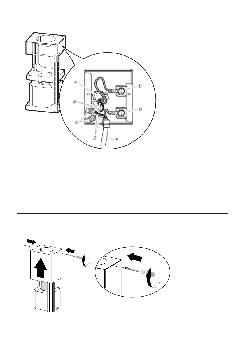
FIGURE 13
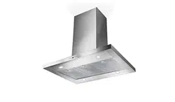
MAKE THE ELECTRICAL CONNECTION
Remove the cover from the eld wiring compartment. (SEE
FIGURE 11) DO NOT turn on the power until installation is
complete! Connect the Power Supply Cable to the rangehood.
Connect the Green (Green and Yellow) ground wire under the
Green grounding screw. Attach the White lead of the power
supply to the White lead of the rangehood with a twist-on type
wire connector. Attach the Black lead of the power supply
to the Black lead of the rangehood with a twist-on type wire
connector.
1. The UPPER CHIMNEY
COVER (C in FIGURE 13)
attaches to the top of the
support structure using two
screws provided (G in FIGURE
13). If using the High Ceiling
Chimney Kit, use the UPPER
CHIMNEY COVER supplied
with the kit. Slide up and
attach the UPPER CHIMNEY
COVER.
2. Attach the duct work to the
DAMPER (M in FIGURE 1).
Make sure to seal all joints with
duct tape to prevent leaks.
3. The LOWER CHIMNEY
COVER (B in FIGURE 13)
attaches using two screws
provided (G in FIGURE 13).
Install the LOWER CHIMNEY
COVER by sliding it up over
the support and the UPPER
CHIMNEY COVER.
For ductless installations, line up the DUCTLESS DIVERTER
EXTENSIONS HORIZONTAL (B in FIGURE 12) with the holes
in the LOWER CHIMNEY COVER (D in FIGURE 12) and snap
in the VENT GRIDS (C in FIGURE 12).
INSTALLING THE RANGEHOOD
A. Home power supply cable
B. Black wires
C. UL listed wire connectors
D.White wires
E. Green (or bare) ground wire from home power supply
connected to green ground screw
F. Range hood power supply cable
G.Range hood power supply cable connected to green
ground screw
FIGURE 11
Ductless installations require
a Ductless Conversion
Kit whose components are
pictured in FIGURE 12. Do
not use the DAMPER (M
in FIGURE 1) for ductless
installations. The LOWER
CHIMNEY COVER ( B
in FIGURE 1) should be
discarded and replaced by
the new one with holes from
the Ductless Conversion Kit
(D in FIGURE 12).
As indicated in FIGURE
12, place the DUCTLESS
DIVERTER (A) over the
exhaust opening of the EASY
CUBE (E). Fit the DUCTLESS
DIVERTER EXTENSIONS
HORIZONTAL (B) into the
DIVERTER (A).
FIGURE 12
FOR DUCTLESS INSTALLATIONS
10
Placez la section supérieure de la cheminée et xez la
partie supérieure au châssis à l'aide des 2 vis enlevées
précédemment.
9
Réalisation des
branchements
Retirez le couvercle du comparti-
ment des câblages externes.
NE METTEZ PAS l'alimentation
sous tension avant d'avoir
terminé l'installation!
Branchez le câble d'alimentation
à la hotte.
Branchez le l vert (vert et jaune)
de mise à la terre sous la vis de
mise à la terre verte. Branchez
le l blanc de l'alimentation
au l blanc de la hotte à l'aide
d'un connecteur verrouillé par
rotation.
Branchez le l noir de
l'alimentation au l noir de la
hotte à l'aide d'un connecteur
verrouillé par rotation.
Remettez le couvercle du compar-
timent des câblages externes et les
ltres à graisse en place.
A. Câble d'alimentation du réseau domestique
B. Fils noirs
C. Serre-lshomologuéUL
D. Fils blancs
E. Fildemiseàlaterrevert(oulnu)del'alimentationdomestiquebranchéàlavisdemiseà
la terre verte
F. Câble d'alimentation de la hotte
G. Câble d'alimentation de la hotte branché à la vis de mise à la terre verte
Loading ...
Loading ...
Loading ...