
Installation Manual
Electric Range
LRE30955S / LRE30855S
LRE30755S / LRE30451S
LRE30757S / LRE30453S
Please read these instructions thoroughly before
installing and operating the range.
P/No.: MFL37118101
Website: http://us.lge.com
2
Part 1 SAFETY
1
BEFORE YOU BEGIN
Remove all tape and packing materials before using the range.
Dispose of all plastic bags after unpacking the range. Never allow children to play with packing materials.
IMPORTANT SAFETY INSTRUCTIONS
Read and follow all instructions before using your oven to prevent the risk of fire, electric shock, personal injury, or
damage when using the range. This guide does not cover all possible conditions that may occur. For further
assistance contact your service agent or manufacturer.
This is the safety alert symbol. This symbol alerts you to potential hazards that can cause personal injury to
you and others. All safety messages will follow the safety alert symbol with either the word “WARNING” or
“CAUTION”.
This symbol will alert you to hazards or unsafe practices which could cause serious
bodily harm or death.
WARNING
This symbol will alert you to hazards or unsafe practices which could cause bodily
injury or property damage.
CAUTION
WARNING
• The information in this manual should be followed exactly.
- A fire or electrical shock may result causing property damage, perasonal injury or death.
• DO NOT step or sit on oven door. Install the Anti-Tip Bracket supplied with the range.
- The range could be tipped and injury might result from spilled hot liquid, food, or the range itself.
- If the range is pulled away from the wall for cleaning, service, or any other reason, ensure that the Anti-Tip Device is properly
reengaged when the range is pushed back against the wall.
• New branch-circuit installations (1996 NEC) for mobile homes, recreational vehicles, and
installations where local codes do not allow grounding through the neutral wire require a 4-
conductor UL listed range cord or 4 wire conduit connection.
• The middle (neutral or ground) wire of a 3 wire power cord or a 3 wire conduit has to be connected
to the middle post of the main terminal block. The remaining two wires of the power cord or
conduit have to be connected to the outside posts of the main terminal connection block.
- Failure to do so can result in electrical shock, severe personal injury or death.
• Only a 4-conductor power-supply cord kit rated 120/240 volts, 50 amperes and marked for use with
ranges with closed-loop connectors or open-end spade lugs with upturned ends shall be used.
The middle (neutral) wire of the power cord or 4-wire conduit has to be connected to the middle
post of the main terminal block. The other two wires of the power cord or conduit have to be
connected to the outside posts of the main terminal connection block. The 4th ground wire must
be connected to the frame of the range with the ground screw.
- Failure to do so can result in electrical shock, severe personal injury or death.
CAUTION
• Make sure that the wall covering, countertop and cabinets around the range can withstand
the heat (up to 194°F) generated by the range.
- Discoloration, delamination or melting may occur.
- This range has been designed to comply with the maximum allowable wood cabinet temperatures of 194°F.
• Cabinet storage space located above the surface units should be avoided.
• Install a range hood that projects horizontally a minimum of 5 inches beyond the bottom of
the cabinets If cabinet storage is to be provided.
- The risk of burns or fire by reaching over the heated surface elements can be reduced.
3
Part 1 SAFETY
PARTS PROVIDED
NOTE
• Read all instructions contained in these installation
instructions before installing range.
• Remove all packing materials from the oven
compartments before connecting the electrical
supply to the range.
• Observe all governing codes and ordinances.
•
Be sure to leave these instructions with the consumer.
NOTE
Keep these instructions with your owner’s manual for
future reference.
• As when using any appliance generating heat, there
are certain safety precautions you should follow.
• Be sure your range is installed and grounded
properly by a qualified installer or service technician.
• Make sure the wall coverings around the range can
withstand the heat generated by the range.
• To eliminate the need to reach over the surface
elements, cabinet storage space above the elements
should be avoided.
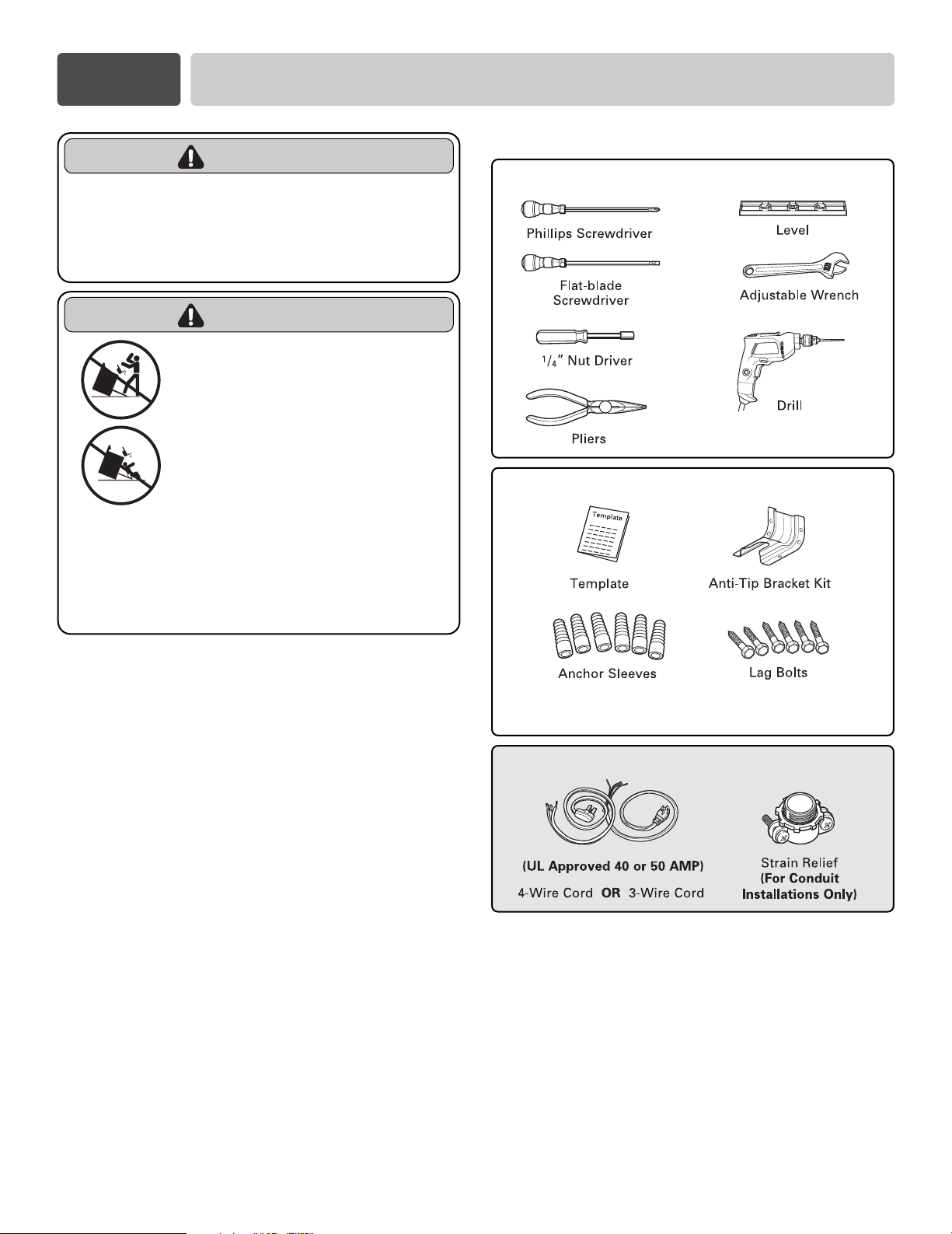
TOOLS NEEDED
PREPARE TO INSTALL THE RANGE
PARTS NOT PROVIDED
WARNING
• The information in this manual
should be followed exactly.
- A fire or electrical shock may result causing
property damage, perasonal injury or death.
WARNING
• DO NOT step or sit on oven
door. Install the Anti-Tip
Bracket supplied with the
range.
- The range could be tipped and
injury might result from spilled hot
liquid, food, or the range itself.
- If the range is pulled away from the
wall for cleaning, service, or any
other reason, ensure that the Anti-
Tip Device is properly reengaged
when the range is pushed back
against the wall.
(For Anti-Tip Bracket Mounted
on Concrete Floors and Walls)
INSTALLATION DRAWINGS
NOTE
SAVE FOR THE USE OF THE LOCAL ELECTRICAL INSPECTOR.
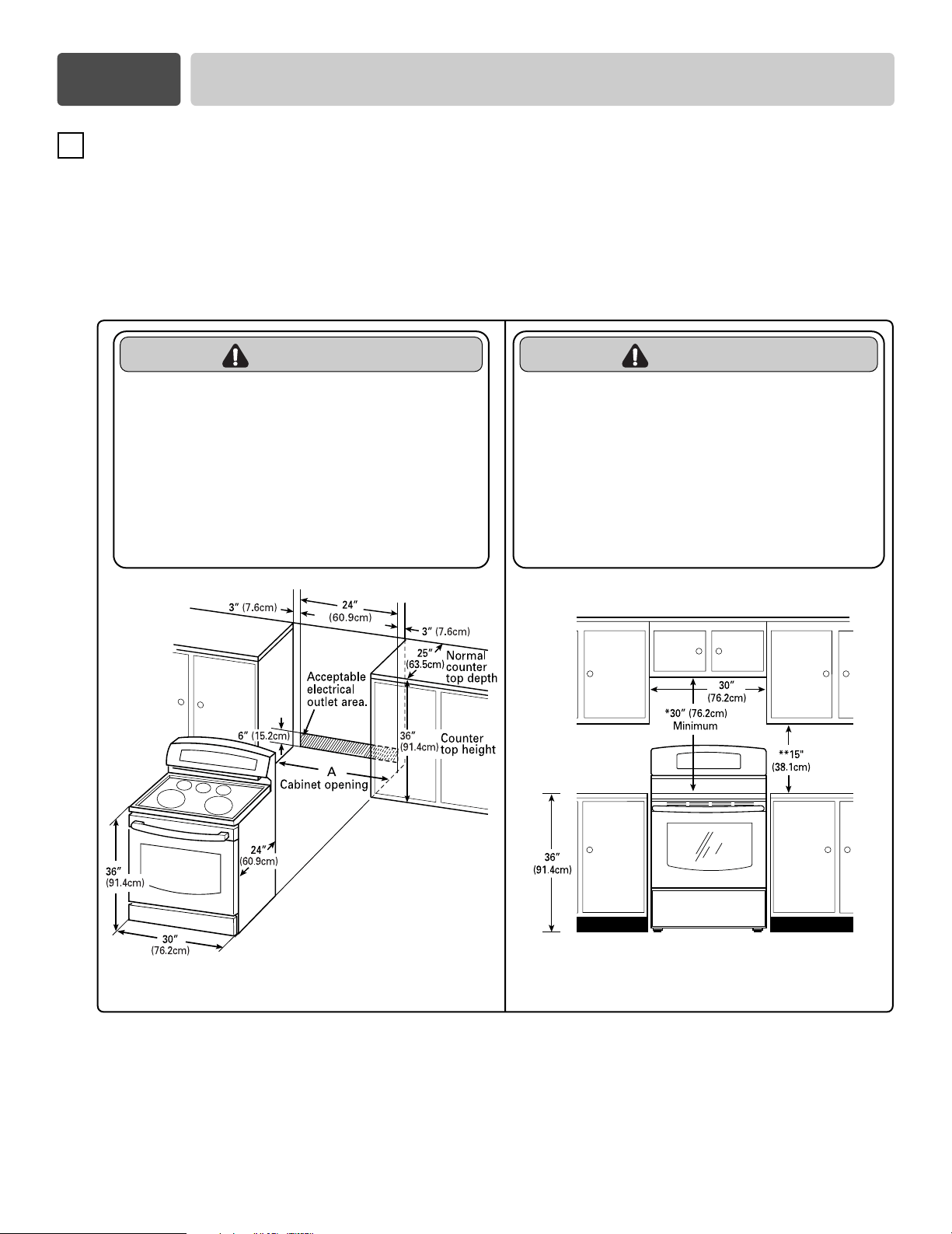
CLEARANCES AND DIMENSIONS (Figure 1)
To install range refer to the following Figure 1.
For installation in CANADA, a Free-standing range is not to be installed closer than
15
/
32 (12mm) from any
adjacent surface.
MINIMUM DIMENSIONS (Figure 2)
* 30”(76.2 cm) minimum clearance between the top of the cooking surface and the bottom of an
unprotected wood or metal cabinet; or 24”(60.9 cm) minimum when bottom of wood or metal cabinet is
protected by not less than
1
/
4”(6.4 cm) flame retardant millboard covered with not less than no. 28 MSG
sheet steel, 0.015”(0.381 mm) stainless steel, 0.024”(0.610 mm) aluminum or 0.020”(0.508 mm) copper.
** 15”(38.1 cm) minimum between countertop and adjacent cabinet bottom.
FIGURE 1 FIGURE 2
A = 30”(76.2 cm) For U.S.A
= 30”(76.2 cm) ~ 31”(78.7 cm) For CANADA
CAUTION
• Make sure that the wall covering,
countertop and cabinets around the
range can withstand the heat (up to
194°F) generated by the range.
- Discoloration, delamination or melting may occur.
- This range has been designed to comply with the
maximum allowable wood cabinet temperatures
of 194°F.
CAUTION
• Cabinet storage space located above
the surface units should be avoided.
• Install a range hood that projects
horizontally a minimum of 5 inches
beyond the bottom of the cabinets If
cabinet storage is to be provided.
- The risk of burns or fire by reaching over the
heated surface elements can be reduced.
4
2
Part 2 PREPARE TO INSTALL THE RANGE
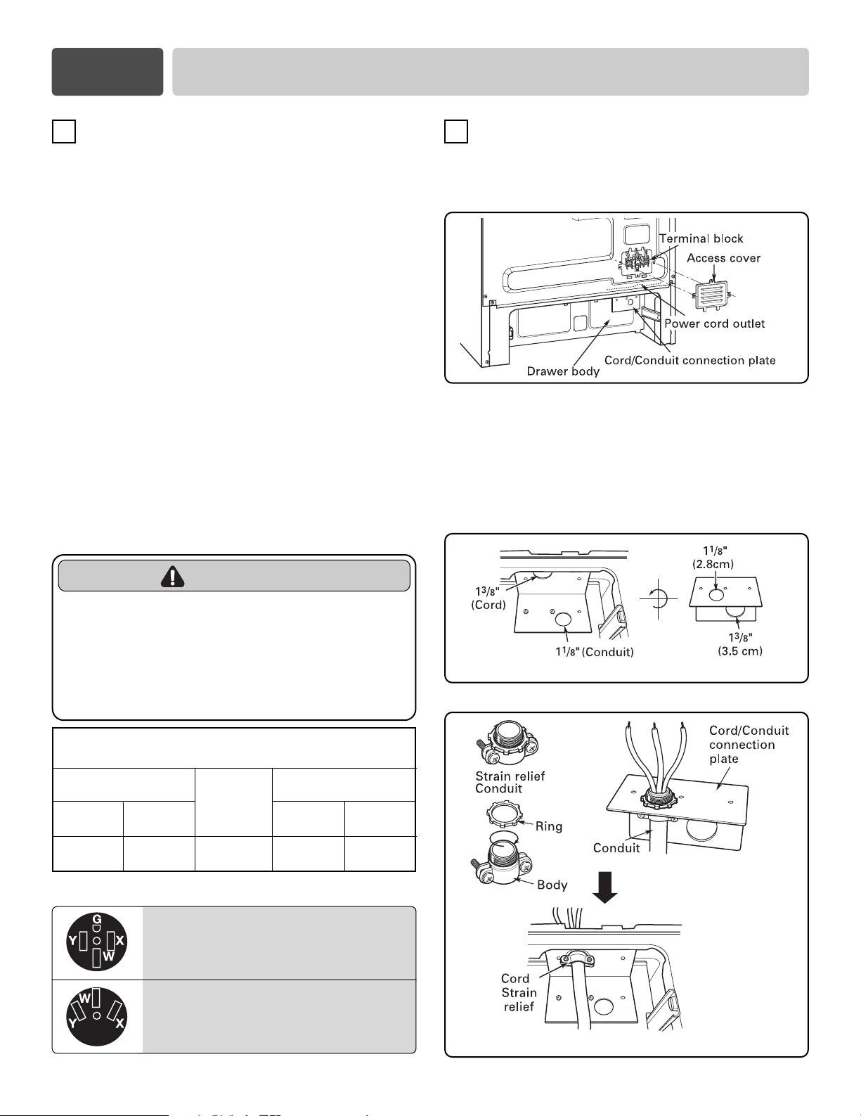
The Cord/Conduit connection plate is used for the
installation of power cord or conduit. For power cord,
install it with the connection plate as INSTALLED. For
conduit, remove the connection plate located below
the rear of the drawer body and use the conduit hole
(1
1
/
8
”) instead of power cord hole (1
3
/
8
”).
(Refer to Figure 5 and 6.)
3, 4 - Wire electrical wall Receptacle
5
3
CONNECT RANGE CORD
The Rear Access cover must be removed. Loosen the
three screws with a screwdriver. The terminal block
will then be accessible.
4
FIGURE 3
FIGURE 4
Range rating, watts
Specified rating
of power-supply-
cord kit, amperes
120/240 volts
3-wire
8,750 - 16,500
16,501 - 22,500
120/208 volts
3-wire
7,801 - 12,500
12,501 - 18,500
40 or 50A
50
Diameter (inches) of Range
connection Opening
Conduit
1
1
/
8
”
1
1
/
8
”
Power cord
1
3
/
8
”
1
3
/
8
”
Specified power-supply-cord kit rating
Part 3 ELECTRICAL CONNECTIONS
ELECTRICAL CONNECTION
REQUIREMENTS
This appliance must be installed and grounded on a
branch circuit by a qualified technician in accordance
with the National Electrical code ANSI/NFPA NO. 70 -
latest edition.
All wiring should conform to Local and NEC. This
range requires a single-phase, 3 wire, A.C 120/208V or
120/240V 60Hz electrical system. Use only a 3-conductor
or a 4-conductor UL-listed range cord with closed-
loop terminals, open-end spade lugs with upturned
ends or similar terminations. DO NOT install the
power cord without a strain relief.
A range cord rated at 40 amps with 120/240 minimum
volt range is required. If a 50 amp range cord is used,
it should be marked for use with 1
3
⁄8
” diameter
connection openings.
This appliance may be connected by means of conduit
or power cord. If conduit is being used, go to page 7
3 wire conduit connections or page 8 for 4 wire
conduit connections.
4 Wire receptacle (14-50R)
3 Wire receptacle (10-50R)
WARNING
• New branch-circuit installations (1996 NEC)
for mobile homes, recreational vehicles,
and installations where local codes do not
allow grounding through the neutral wire
require a 4-conductor UL listed range cord
or 4 wire conduit connection.
FIGURE 5
FIGURE 6
Remove the Conduit connection plate
Assemble the
strain relief hole
Reinstall the Cord/Conduit connection plate
6
Part 3 ELECTRICAL CONNECTIONS
FIGURE 7
FIGURE 8
3-wire connection
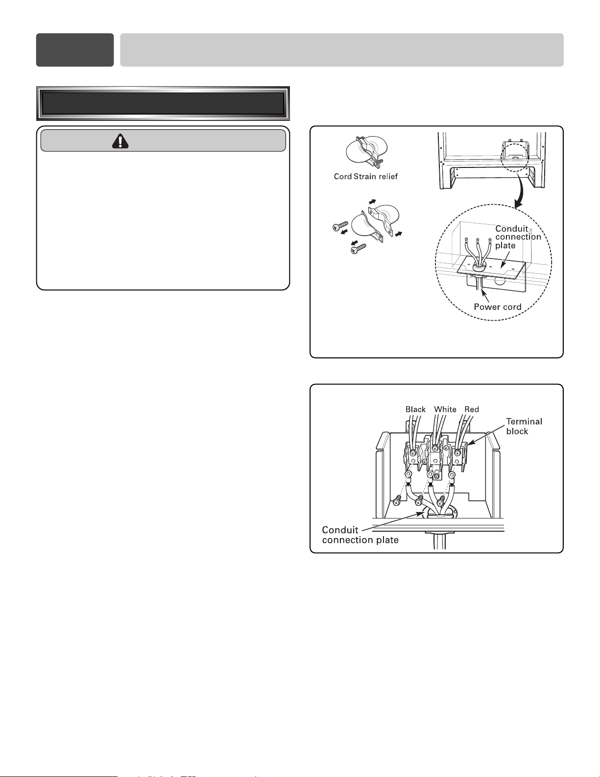
Assemble the strain relief
to the 1
3
/
8
” opening in
Conduit connection plate
Separate Strain Relief
before installation
3-wire connection with a power supply cord
WARNING
• The middle (neutral or ground) wire of a 3
wire power cord or a 3 wire conduit has to
be connected to the middle post of the
main terminal block. The remaining two
wires of the power cord or conduit have to
be connected to the outside posts of the
main terminal connection block.
- Failure to do so can result in electrical shock, severe
personal injury or death.
Install the power cord as follows:
For power cord installations, Hook the strain relief
over the power cord hole (1
3
/
8
”) located below the rear
of drawer body. Insert the power cord through the
strain relief and tighten it. (Refer to Figure 7.)
DO NOT install the power cord without a strain relief.
1. Remove the lower 3 screws from the terminal block
and retain them. (Refer to Figure 8.)
2. Insert the 3 screws through each power cord
terminal ring and into the lower terminals of the
terminal block.
Make sure that the center wire (white/neutral) is
connected to the center lower position of the
terminal block.
3. Tighten 3 screws securely into the terminal block.
Do not remove the ground strap connections.
4. Go to page 9.
7
Part 3 ELECTRICAL CONNECTIONS
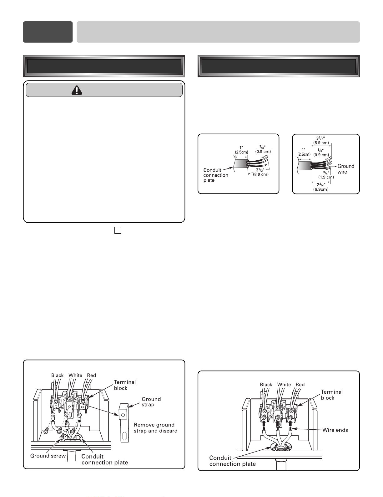
Follow the instructions under “
CONNECT RANGE
CORD
” on page 5 to correctly install the strain relief.
1. Remove the lower 3 screws from the terminal block
and retain them. (Refer to Figure 9.)
Remove the ground screw and retain it.
2. Remove ground strap and discard as shown
in Figure 9.
Do not discard any screws.
3. Insert the ground screw into the power cord ground
wire terminal ring and secure it to the range frame.
4. Insert the 3 screws through each power cord
terminal ring and into the lower terminals of the
terminal block. Make sure that the center wire
(white/neutral) is connected to the center lower
position of the terminal block.
Tighten 3 screws securely into the terminal block.
5. Go to page 9.
Install the conduit as follows:
Remove the Conduit connection plate from the rear of
drawer body and rotate it as shown in Figure 5. The
conduit hole (1
1
/
8
”) must be used.
First, prepare conduit wires as shown in Figure 10.
Second, install conduit as shown in Figure 6.
For conduit installations, after purchasing a strain
relief, insert it in the conduit hole (1
1
/
8
”). Then install
the conduit through the body of strain relief and
fasten the strain relief with its ring. Reinstall the
bracket.
For conduit connections :
If the wire in the conduit is copper it must be 8 or 10
AWG wiring.
If the wire in the conduit is aluminum it must be 6 or 8
AWG wiring.
1. Loosen the lower 3 screws from the terminal block.
(Refer to Figure 11.)
2. Insert the bare wire (white/neutral) end through the
center terminal block opening.
Do not remove ground strap connections.
3. Insert the two side bare wire ends into the lower left
and the lower right terminal block opening.
Tighten the 3 screws securely into the terminal block.
(approximately 35 - 50 IN-LB)
4. Go to page 9.
FIGURE 10
3-wire connection: conduit
or
3 wire 4 wire
FIGURE 9
4-wire connection
4-wire connection with a power supply cord
WARNING
• Only a 4-conductor power-supply cord kit
rated 120/240 volts, 50 amperes and
marked for use with ranges with closed-
loop connectors or open-end spade lugs
with upturned ends shall be used. The
middle (neutral) wire of the power cord or
4-wire conduit has to be connected to the
middle post of the main terminal block. The
other two wires of the power cord or
conduit have to be connected to the
outside posts of the main terminal
connection block. The 4th ground wire
must be connected to the frame of the
range with the ground screw.
- Failure to do so can result in electrical shock, severe
personal injury or death.
4
FIGURE 11
3-wire connection
8
Part 3 ELECTRICAL CONNECTIONS
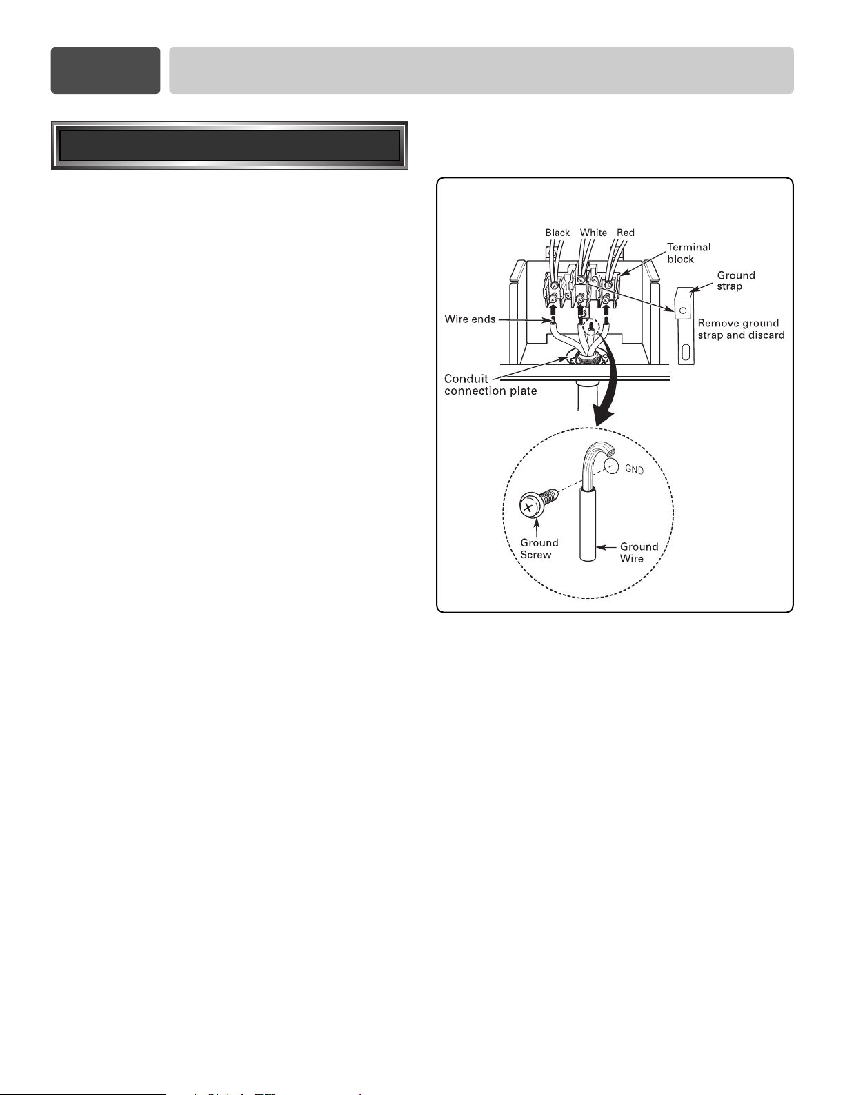
1. Follow the instructions under “Install the conduit as
follows” on page 7 to correctly install the strain
relief.
DO NOT install the conduit without a strain relief.
2. Loosen the 2 lower left and right screws from the
terminal block. (Refer to Figure 12.)
Remove the lower 2 center screws.
3. Remove ground strap and discard as shown
in Figure 12.
Do not discard any screws.
4. Attach the ground bare wire end to range frame
and secure it in place with the ground screw (Refer
to figure 12.)
5. Insert the bare wire (white/neutral) end through the
center terminal block opening.
6. Insert the two side bare wire ends into the left and
the right terminal block opening.
Tighten the 3 screws securely into the terminal
block. (approximately 35 - 50 IN-LB)
7. Go to page 9.
FIGURE 12
4-wire connection
4-wire connection: conduit
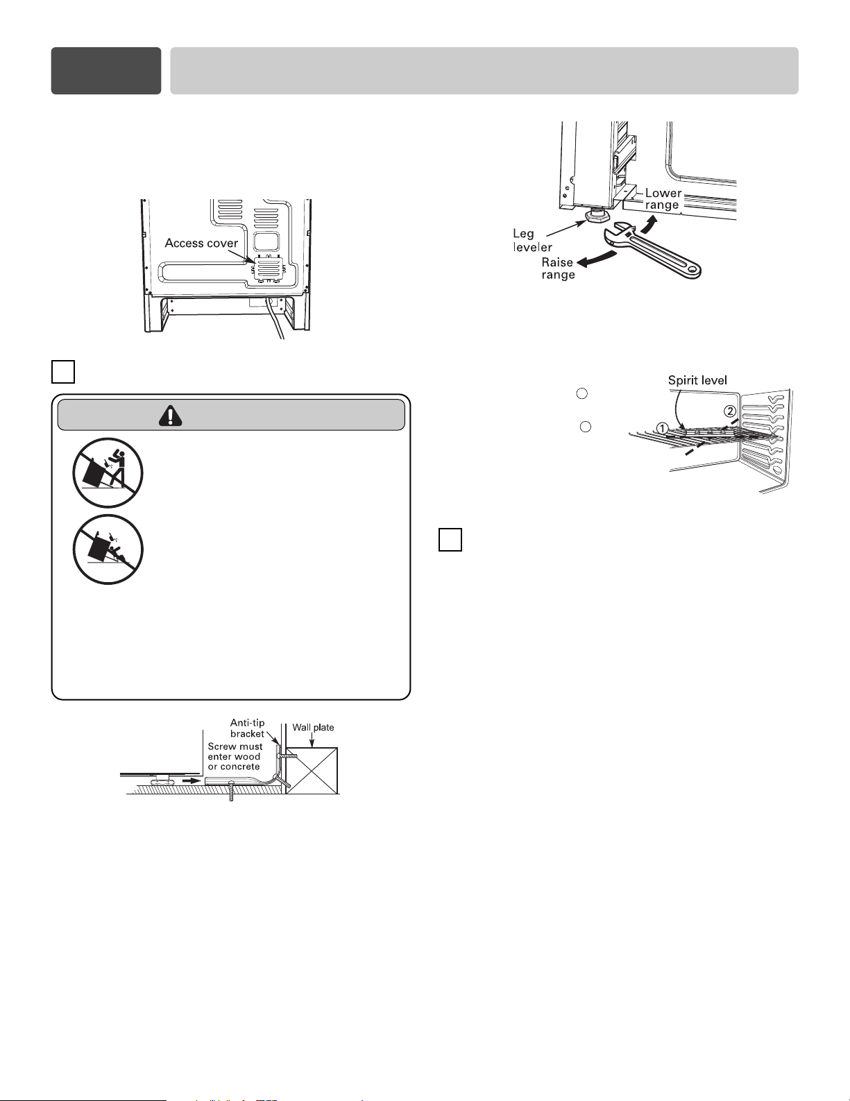
Replace the access cover on the range back. To
replace the wire cover, insert double projections in the
pockets located below the opening and tighten the
three screws.
ANTI-TIP DEVICE INSTALLATION
1. Locate the bracket using the template
An Anti-tip bracket is packaged with template. The
instructions include necessary information to
complete the installation.
Read and follow range installation instruction sheet
(template).
2. Level the range
Level the range by adjusting the leveling legs with a
wrench.
9
Use a spirit level to check your adjustments. Place the
level diagonally on the oven rack, and check each
direction for level.
First check direction 1
.
After check direction
2
.
If the spirit level doesn’t show
level on the rack, adjust the
leveling legs with a wrench.
FINAL INSTALLATION
• Move range close enough to the opening to plug
into the receptacle.
• Slide range into position insuring that the left back
leg slides under the anti-tip bracket. Range will sit 0”
away from the back wall when properly installed.
• Carefully tip range forward to insure that the anti-tip
bracket engages the range back brace and prevents
tip-over.
• Turn on electrical power. Check range for proper
operation as described in owner’s manual.
5
6
Part 4 INSTALL THE RANGE
WARNING
• DO NOT step or sit on oven
door. Install the Anti-Tip
Bracket supplied with the
range.
- The range could be tipped and
injury might result from spilled hot
liquid, food, or the range itself.
- If the range is pulled away from the
wall for cleaning, service, or any
other reason, ensure that the Anti-
Tip Device is properly reengaged
when the range is pushed back
against the wall.


Manual de instalación
Estufa eléctrica
LRE30955S / LRE30855S
LRE30755S / LRE30451S
LRE30757S / LRE30453S
Sírvase leer cuidadosamente estas instrucciones
antes de instalar y poner a funcionar la estufa.
Número de pieza : MFL37118101
Sitio Web: http://us.lge.com
ANTES DE COMENZAR
Quite todas las cintas y materiales de embalaje antes de usar la cocina.
Elimine todas las bolsas de plástico después de desempacar la cocina. Nunca permita que los niños jueguen con los
materiales de empaque.
INSTRUCCIONES IMPORTANTES DE SEGURIDAD
Lea y siga todas las instrucciones antes de utilizar su cocina para evitar el riesgo de incendio, descarga eléctrica,
lesiones personales o daños cuando use la cocina. Esta guía no cubre todas las condiciones posibles que pueden
ocurrir. Para mayor asistencia, comuníquese con su agente de servicios o fabricante.
2
Sección 1
SEGURIDAD
1
Este es el símbolo de alerta de seguridad. Este símbolo lo alerta sobre peligros potenciales que pueden
matarlo a lastimarlo a usted o a otros. Todos los mensajes de seguridad se encontrarán después de los
símbolos de alerta de seguridad y de las palabras "ADVERTENCIA" O "PRECAUCIÓN".
Este símbolo lo alerta sobre peligros o prácticas poco seguras que podrían
provocar lesiones personales graves o la muerte.
ADVERTENCIA
Este símbolo lo alerta sobre peligros o prácticas poco seguras que podrían
provocar lesiones personales o daños a la propiedad.
PRECAUCIÓN
ADVERTENCIA
PRECAUCIÓN
• Verifique que el empapelado, la mesada y los gabinetes ubicados alrededor de la cocina soporten el
calor (hasta 194°F) generado por la cocina.
- Puede provocarse decoloración, delaminación o derretimiento.
- Esta cocina ha sido diseñada para cumplir con las temperaturas máximas permitidas de gabinetes de madera de 194°F.
•
Debe evitarse la colocación de espacios de almacenamiento de gabinetes sobre las unidades de superficie.
• Instale una campana de cocina que se proyecte de manera horizontal en un mínimo de 5 pulgadas
más allá de la parte inferior de los gabinetes, si es que debe incluirse almacenamiento de gabinetes.
- Puede reducirse el riesgo de quemaduras o incendios por inclinarse sobre los elementos de superficie calientes.
• La información de este manual debe seguirse al pie de la letra.
- Puede provocarse una descarga eléctrica generando daños a la propiedad, lesiones personales o la muerte.
•
NO se pare o siente en la puerta del horno. Instale el soporte anti-volcaduras incluido con la cocina.
- La cocina puede volcarse y puede provocar lesiones debido al derrame de líquidos y alimentos calientes o la cocina misma.
- Cuando se jala la estufa de la pared por motivos de limpieza, servicio u otra razón, asegúrese de volver a embonar correctamente
el Dispositivo Antivolcadura al volver a empujar la estufacontra la pared.
• Las instalaciones nuevas en circuitos derivados (1996 NEC) para casas rodantes, vehículos
recreativos e instalaciones donde los códigos locales no permiten la conexión a tierra a través del
cable neutral requieren un cable de cocina listado UL de cuatro conductores o una conexión de
conductores de 4 cables.
• El cable medio (neutral o a tierra) de un cable de energía de 3 clavijas o un conducto de 3 clavijas
debe conectarse a la posición media del bloque terminal principal. Las dos clavijas restantes del
cable de energía o conducto deben estar conectados a las posiciones externas del bloque de
conexión terminal principal.
-
No hacerlo puede provocar una descarga eléctrica, lesiones personales graves o la muerte.
•
Sólo deberá utilizarse un equipo con cable de energía de 4 conductores clasificado 120/240 voltios, 50
amperios y marcado para utilizar con cocinas con conectores de bucle cerrado o pernos de pala de
extremos abiertos con bordes elevados. La clavija media (neutral) del cable de energía o conducto de 4
clavijas debe conectarse a la posición media del bloque terminal principal. Las otras dos clavijas del
cable de energía o conducto deben conectarse a las posiciones externas del bloque de conexión terminal
principal. La cuarta clavija a tierra debe conectarse al marco de la cocina con el tornillo a tierra.
- No hacerlo puede provocar una descarga eléctrica, lesiones personales graves o la muerte.
3
PIEZAS PROVISTAS
NOTA
• Antes de instalar la estufa lea todas las instrucciones
incluidas en estas instrucciones de instalación.
• Antes de conectar la fuente de alimentación
eléctrica debe quitar todos los materiales de
empaque del compartimiento del horno.
• Cumpla con todos los códigos y ordenanzas vigentes.
•
Siempre deje estas instrucciones con el consumidor.
NOTA
Conserve estas instrucciones junto con su manual del
propietario para cualquier consulta en el futuro.
• Al igual que cuando se utiliza cualquier artefacto que
genera calor, deben seguirse ciertas precauciones de
seguridad.
• Cerciórese de que su estufa sea instalada y conectada
a tierra correctamente por un instalador o técnico de
servicio calificado.
• Cerciórese de que todos los adornos o recubrimientos
de la pared que están alrededor de la estufa tienen
la capacidad de resistir el calor generado por la
misma.
• Se debe evitar el uso de gabinetes de
almacenamiento encima de la estufa para no tener
que alcanzarlos por encima de los elementos de
cocción.
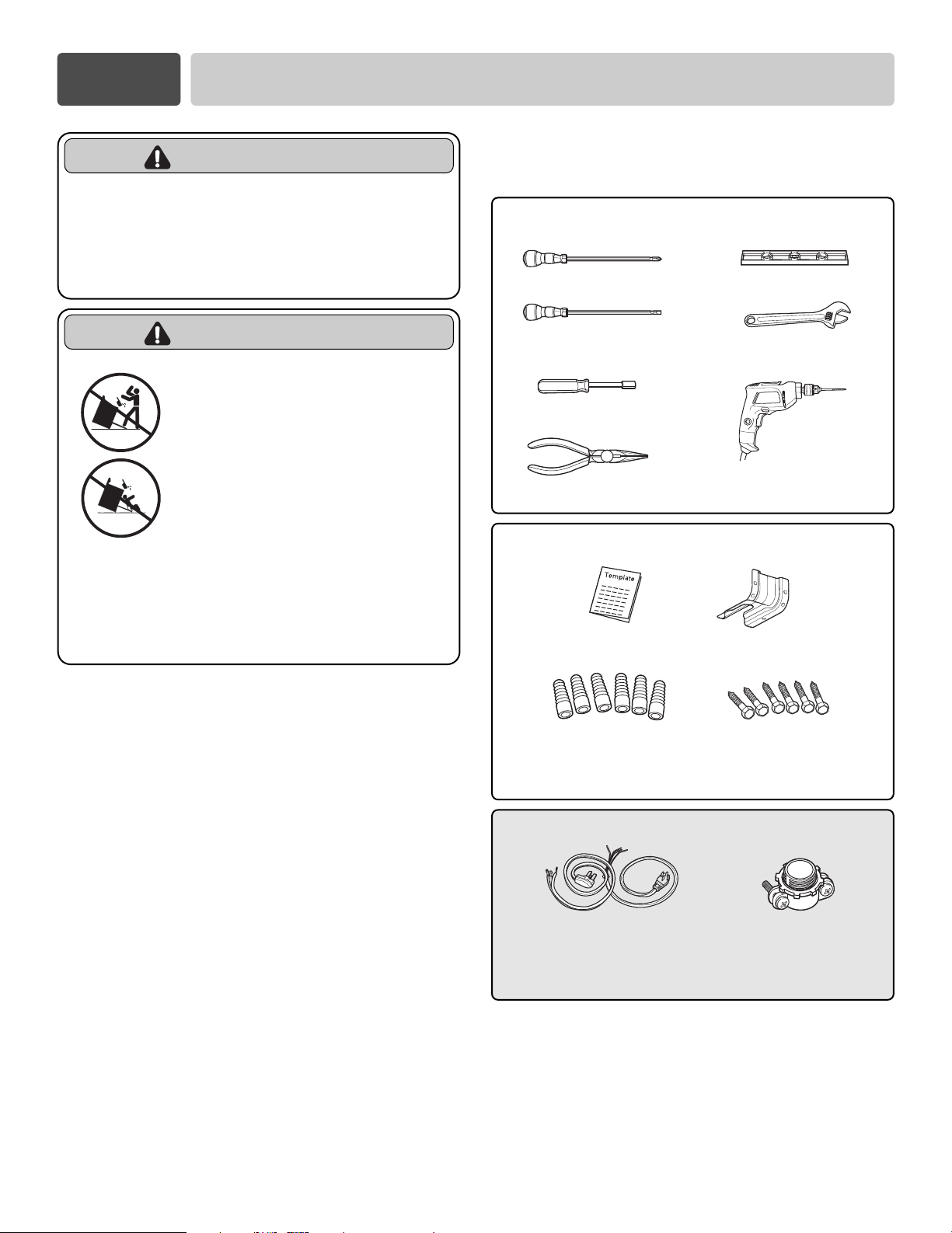
HERRAMIENTAS NECESARIAS
Sección 1
SEGURIDAD
PREPARATIVOS PARA INSTALAR LA
ESTUFA
PIEZAS NO PROVISTAS
Destornillador Phillips
Nivel
Llave de
tuercas ajustable
Taladro
Destornillador
de hoja plana
Llave de caja de 1/4”
Alicates
Plantilla
Manguitos de anclaje
(Aprobado por la UL
para 40 0 50 AMPS)
Tensor de alivio
(Solamente para
instalaciones con
conducto portacables)
Cable de 4 alambres o de 3
alambres
(Solamente cuando se instala la ménsula
de anti-volcadura en pisos de concreto)
Juego de ménsula
anti-volcaduras
Pernos de fijación
ADVERTENCIA
• La información de este manual debe
seguirse al pie de la letra.
- Puede provocarse una descarga eléctrica
generando daños a la propiedad, lesiones
personales o la muerte.
• NO se pare o siente en la
puerta del horno. Instale el
soporte anti-volcaduras
incluido con la cocina.
- La cocina puede volcarse y puede
provocar lesiones debido al derrame
de líquidos y alimentos calientes o la
cocina misma.
- Cuando se jala la estufa de la pared
por motivos de limpieza, servicio u
otra razón, asegúrese de volver a
embonar correctamente el
Dispositivo Antivolcadura al volver a
empujar la estufacontra la pared.
ADVERTENCIA
4
ILUSTRACIONES DE INSTALACIÓN
NOTA
GUÁRDELO PARA EL USO DEL INSPECTOR LOCAL DE INSTALACIONES ELÉCTRICAS.
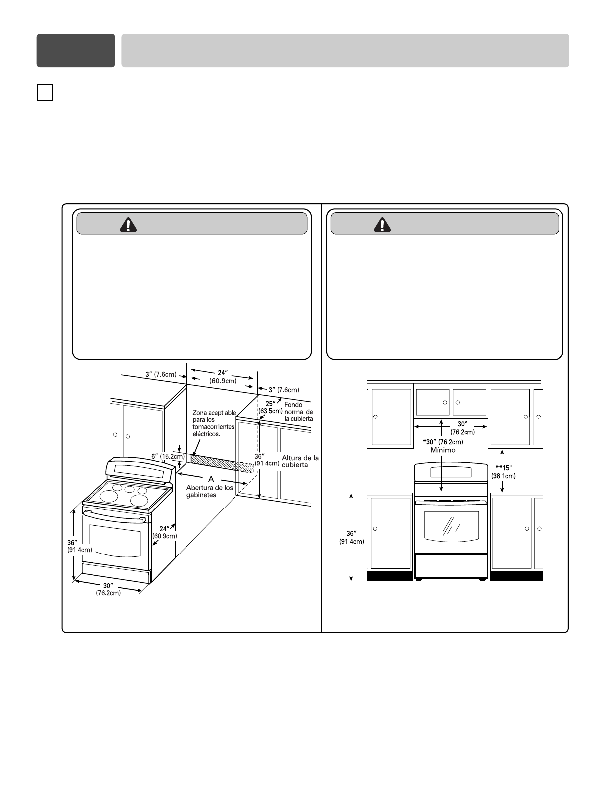
HOLGURAS Y DIMENSIONES (Figura 1)
Consulte la figura 1 a continuación para la instalación de la estufa.
Si se va a instalar en CANADÁ, una estufa autónoma no podrá instalarse a menos de
15
/
32 (12mm) de
cualquier superficie adyacente.
DIMENSIONES MÍNIMAS (Figura 2)
* 30”(76.2 cm) de holgura mínima entre la cubierta de la superficie de cocción y la base de un gabinete de
madera o de metal sin protección; o 24”(60.9 cm) como mínimo cuando la parte inferior de un gabinete
de madera o de metal está protegida por una capa de
1
/
4”(6.4 mm) de cartón gris resistente al fuego y
recubierta cuando menos con lámina de acero no. 28 MSG , 0.015”(0.381 mm) de acero inoxidable,
0.024”(0.610 mm) de aluminio o 0.020”(0.508 mm) de cobre.
** 15” (38.1 cm) como mínimo entre la cubierta de los gabinetes y la parte inferior del gabinete adyacente.
2
FIGURA 1
FIGURA 2
A = 30” (76.2 cm) Para EE.UU.
= 30” (76.2 cm) ~ 31” (78.7 cm) Para CANADÁ
Sección 2
PREPARATIVOS PARA INSTALAR LA ESTUFA
PRECAUCIÓN
•
Verifique que el empapelado, la mesada
y los gabinetes ubicados alrededor de
la cocina soporten el calor (hasta 194°F)
generado por la cocina.
- Puede provocarse decoloración, delaminación o
derretimiento.
- Esta cocina ha sido diseñada para cumplir con
las temperaturas máximas permitidas de
gabinetes de madera de 194°F.
PRECAUCIÓN
• Debe evitarse la colocación de espacios de
almacenamiento de gabinetes sobre las
unidades de superficie.
• Instale una campana de cocina que se
proyecte de manera horizontal en un
mínimo de 5 pulgadas más allá de la parte
inferior de los gabinetes, si es que debe
incluirse almacenamiento de gabinetes.
- Puede reducirse el riesgo de quemaduras o incendios por
inclinarse sobre los elementos de superficie calientes.
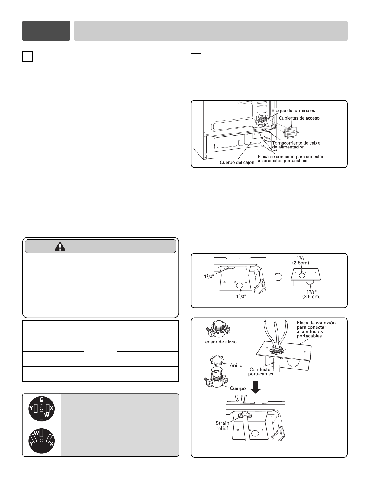
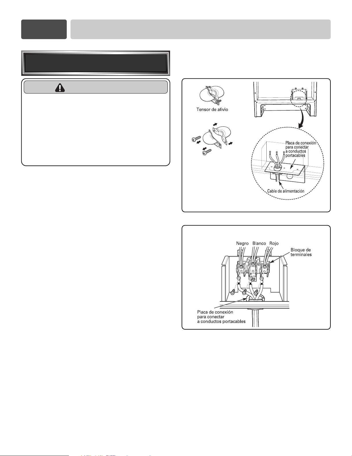
Para la instalación del cable de alimentación o de
conducto portacables se deben usar placas de conexión
para conectar a conductos portacables. El cable de
alimentación deberá instalarse con la placa de conexión
de conductos portacables provista por el fabricante. En
el caso de conductos portacables, quite la placa de
conexión de conductos portacables que está ubicada
debajo de la parte posterior del cuerpo del cajón y use el
orificio del conducto portacables (1
1
/
8
” (2.8 cm)) en lugar
del orificio del cable de alimentación (1
3
/
8
” (3.5 cm)).
(Consulte la Figura 8.)
3, Tipos de tomacorriente de pared de 4 alambres.
5
3
CÓMO CONECTAR EL CABLE DE LA
ESTUFA
Debe quitarse la cubierta de acceso posterior. Use un
destornillador para aflojar los tres tornillos. Entonces se
podrá tener acceso a un bloque de terminales.
4
FIGURA 3
FIGURA 4
Capacidad nominal de la
estufa. Vatios
Clasificación
nominal
especificada para
el juego de cable
de alimentación,
amperios
120/240 voltios
3 alambres
8,750 - 16,500
16,501 - 22,500
120/208 voltios
3 alambres
7,801 - 12,500
12,501 - 18,500
40 o 50A
50
Diámetro (en pulgadas) de la
abertura de conexión de la estufa
Conducto
portacables
1
1
/
8
”
1
1
/
8
”
Cable de
alimentación
1
3
/
8
”
1
3
/
8
”
Clasificación nominal especificada para el
juego del cable de alimentación
Sección 3
CONEXIONES ELÉCTRICAS
REQUISITOS DE LAS CONEXIONES
ELÉCTRICAS
Este artefacto deberá instalarse y conectarse a tierra en un
circuito de red por un técnico certificado, de acuerdo con la
edición más reciente del código de la National Electrical
code ANSI/NFPA NO. 70
Todo el alambrado deberá conformarse a Local y NEC. Esta
estufa requiere de un sistema eléctrico monofásico, de 3
alambres, 120/208 V C.A. o 120/240 V 60Hz. Use solamente
un cable de 3 o 4 alambres para estufa reconocido por la UL,
con terminales de ojillo cerrado, lengüetas de pala con
extremos doblados o terminales parecidas. NO instale el
cable de alimentación sin un protector.
Es necesario un cable para estufa con capacidad nominal de
120/240 V a 40 amps. Si se llegara a usar un cable de estufa
de 50 amps., deberá estar marcado como para ser utilizado
en aberturas de conexión de 13.8” (3.5 cm) de diámetro.
Este artefacto puede conectarse usando un conductor de
cable o cable de alimentación. Si se utilizan conductos
portacables, consulte la página 7.
Conexiones de conductos portacables con 3 alambres o la
página 8 para las conexiones de conductos portacables con
4 conductores.
Tomacorriente de
4 alambres (14-50R)
Tomacorriente de
3 alambres (10-50R)
ADVERTENCIA
• Las instalaciones nuevas en circuitos
derivados (1996 NEC) para casas
rodantes, vehículos recreativos e
instalaciones donde los códigos locales
no permiten la conexión a tierra a través
del cable neutral requieren un cable de
cocina listado UL de cuatro conductores o
una conexión de conductores de 4 cables.
FIGURA 5
FIGURA 6
Quite la placa de conexión de conductos portacables
Ensamble el orificio
del tensor de alivio
Vuelva a instalar la placa de conexión para
conectar a conductos portacables
6
Instale el cable de alimentación como sigue:
Para las instalaciones del cable de alimentación, enganche
el tensor de alivio al orificio del cable de alimentación (1
3
/
8
”
(3.5 cm)) ubicado debajo de la parte posterior del cuerpo del
cajón. Inserte el cable de alimentación a través del tensor de
alivio y apriételo. (Consulte la Figura 7.)
NO instale el cable de alimentación sin un protector.
1. Quite los tres tornillos inferiores del bloque de terminales
y consérvelos. (Ver Figura 8).
2. Introduzca los 3 tornillos a través del anillo de cada
terminal del cable de energía y dentro de las terminales
inferiores del bloque de terminales. Verifique que el cable
central (blanco/neutral) esté conectado en la posición
inferior central del bloque de terminales.
3. Ajuste bien los 3 tornillos al bloque de terminales.
No retire las conexiones de descarga a tierra.
4. Diríjase a la página 9.
Sección 3
CONEXIONES ELÉCTRICAS
FIGURA 7
FIGURA 8
Conexión de 3 alambres
Monte el aliviador de tensión
en el orificio de
1
3
/
8
”
(3.5 cm)
de la placa de conexión del
conducto portacables
Separe el aliviador de
tensión antes de instalarlo.
Conexión de 3 alambres
con un cable de alimentación
ADVERTENCIA
• El cable medio (neutral o a tierra) de un cable
de energía de 3 clavijas o un conducto de 3
clavijas debe conectarse a la posición media
del bloque terminal principal. Las dos clavijas
restantes del cable de energía o conducto
deben estar conectados a las posiciones
externas del bloque de conexión terminal
principal.
- No hacerlo puede provocar una descarga eléctrica,
lesiones personales graves o la muerte.
7
Sección 3
CONEXIONES ELÉCTRICAS
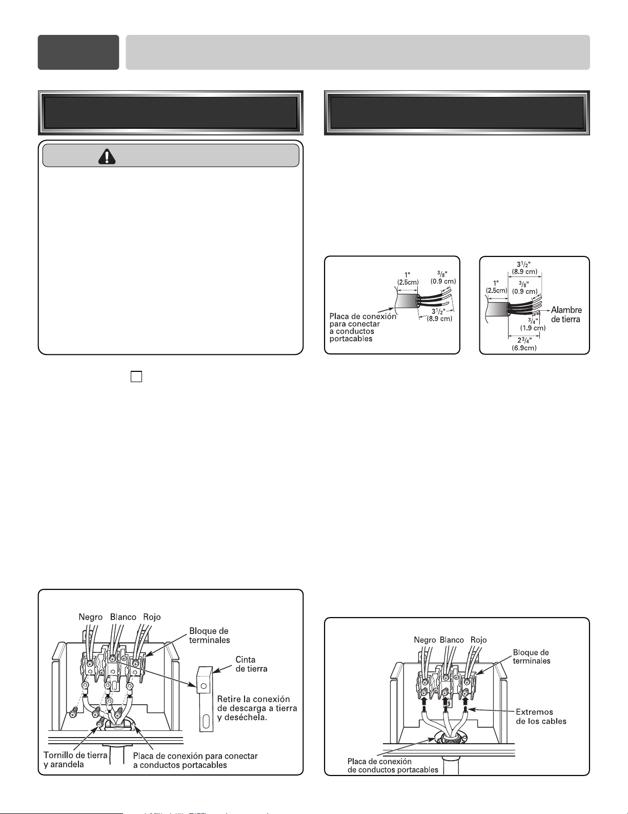
Para instalar correctamente el tensor de alivio, siga
las instrucciones “ CÓMO CONECTAR EL CABLE
DE LA ESTUFA ” en la página 5.
1.
Quite los tres tornillos inferiores del bloque de
terminales y consérvelos. (Ver Figura 9).
Quite el tornillo a tierra y consérvelo.
2. Retire la conexión de descarga a tierra y deséchela
como puede verse en la Figura 9.
No deseche los tornillos.
3. Introduzca el tornillo a tierra en el anillo de terminal
de tierra del cable de energía y fíjelo al marco.
4. Introduzca los 3 tornillos a través de los anillos de
las terminales del cable de energía y dentro de las
terminales inferiores del bloque de terminales.
Verifique que el cable central (blanco/neutral) esté
conectado en la posición inferior central del bloque
de terminales. Ajuste bien los 3 tornillos al bloque
de terminales.
5. Diríjase a la página 9.
Instale el conducto portacables de la
manera siguiente:
Q
uite la placa de conexión de conductos portacables de la parte
posterior del cuerpo del cajón y déle vuelta como se muestra en
la figura 5. Debe usarse el orificio de conducto portacables (1
1
/
8
”
(2.8 cm)).
En primer término, prepare los cables del conducto como
puede verse en la Figura 10.
En segundo término, instale el conducto pasacables como
puede verse en la Figura 6.
Para instalar conductos pasacables, después de adquirir un
aliviador de tensión, introdúzcalo en el orificio del conducto
pasacables (1
1
/
8
” (2.8 cm)). Luego instale el conducto a través
del cuerpo del aliviado de tensión y sujete el aliviador de
tensión con su anillo. Vuelva a instalar el soporte.
Para la conexión de conductos portacables :
Si el cable del conducto es cobre, la conexión eléctrica debe ser
de 8 o 10 AWG.
Si el cable del conducto es aluminio, la conexión eléctrica debe
ser de 6 o 8 AWG.
1. Afloje los 3 tornillos inferiores del bloque de terminales. (Ver
Figura 11).
2. Introduzca el extremo del cable desnudo (blanco/neutral) a
través del centro del orificio del bloque de terminales.
No quite las conexiones de descarga a tierra.
3. Introduzca los dos extremos de cable desnudo en los orificios
del bloque de terminales inferiores izquierdo y derecho.
Ajuste bien los 3 tornillos en el bloque de terminales
(aproximadamente 35 - 50 pul/lb)
4. Diríjase a la página 9.
FIGURA 10
or
3 alambres 4 alambres
Conexión de 3 alambres
conducto portacables
FIGURA 7
Conexión de 4 alambres
Conexión de 4 alambres
con un cable de alimentación
ADVERTENCIA
• Sólo deberá utilizarse un equipo con cable de
energía de 4 conductores clasificado 120/240 voltios,
50 amperios y marcado para utilizar con cocinas con
conectores de bucle cerrado o pernos de pala de
extremos abiertos con bordes elevados. La clavija
media (neutral) del cable de energía o conducto de 4
clavijas debe conectarse a la posición media del
bloque terminal principal. Las otras dos clavijas del
cable de energía o conducto deben conectarse a las
posiciones externas del bloque de conexión terminal
principal. La cuarta clavija a tierra debe conectarse al
marco de la cocina con el tornillo a tierra.
- No hacerlo puede provocar una descarga eléctrica,
lesiones personales graves o la muerte.
4
FIGURA 11
Conexión de 3 alambres
8
Sección 3
CONEXIONES ELÉCTRICAS
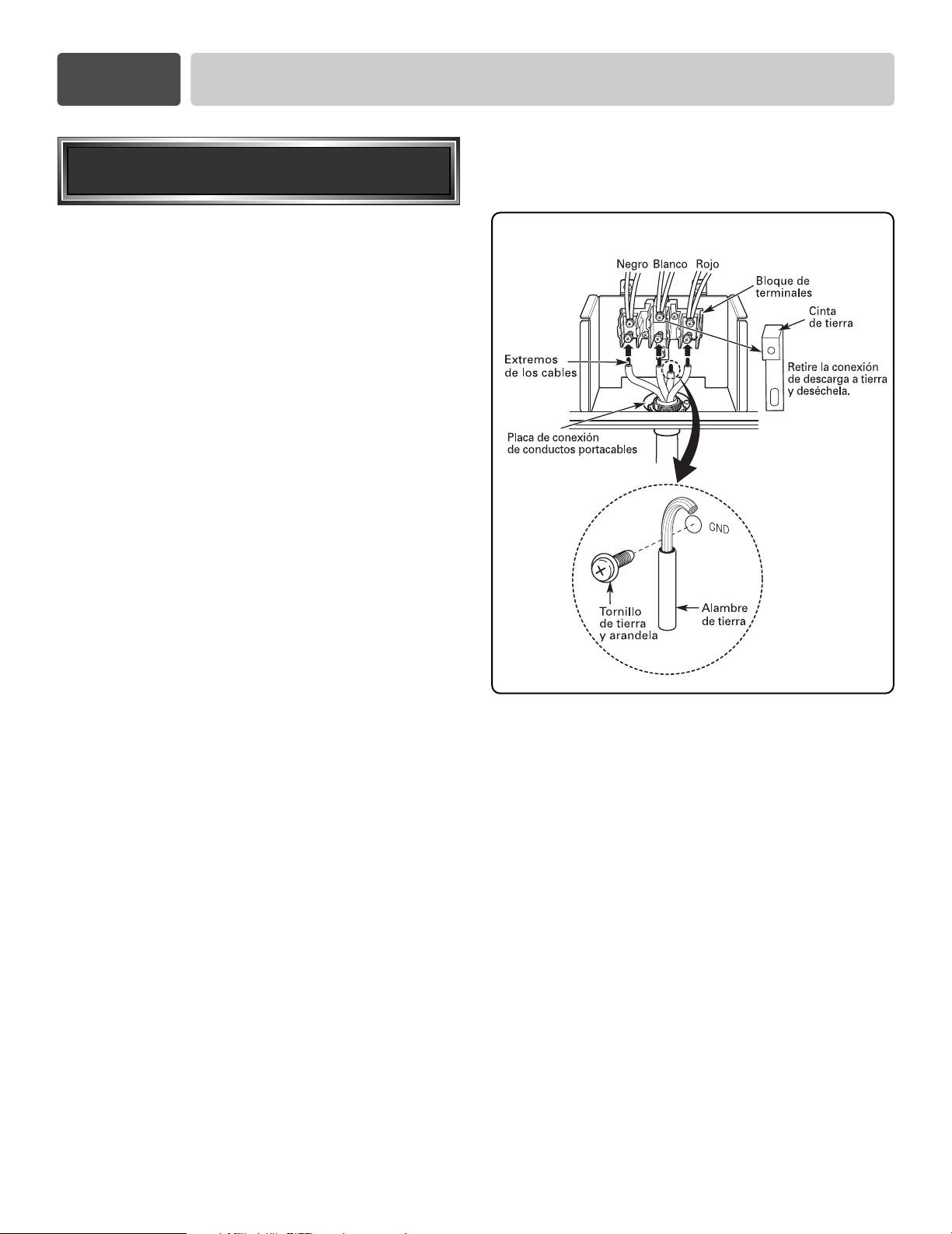
1. Siga las instrucciones de “Cómo instalar el
conducto pasacables” de la página 7 para instalar el
aliviador de tensión de manera correcta.
NO instale el conducto sin un protector.
2. Afloje los 2 tornillos inferiores izquierdo y derecho
del bloque de terminales. (Ver Figura 12).
Quite los 2 tornillos centrales inferiores.
3. Retire la conexión de descarga a tierra y deséchela
como puede verse en la Figura 12.
No deseche los tornillos.
4. Conecte el extremo del cable desnudo con
conexión a tierra al marco y asegúrelo en su lugar
con el tornillo a tierra. (Ver Figura 12).
5. Introduzca el extremo del cable desnudo
(blanco/neutral) a través del orificio central del
bloque de terminales.
6. Introduzca los dos extremos de cable desnudo en
los orificios del bloque de terminales izquierdo y
derecho. Ajuste bien los 3 tornillos en el bloque de
terminales (aproximadamente 35 - 50 pul./lb).
7. Diríjase a la página 9.
FIGURA 12
Conexión de 4 alambres
Conexión de 4 alambres
conducto portacables
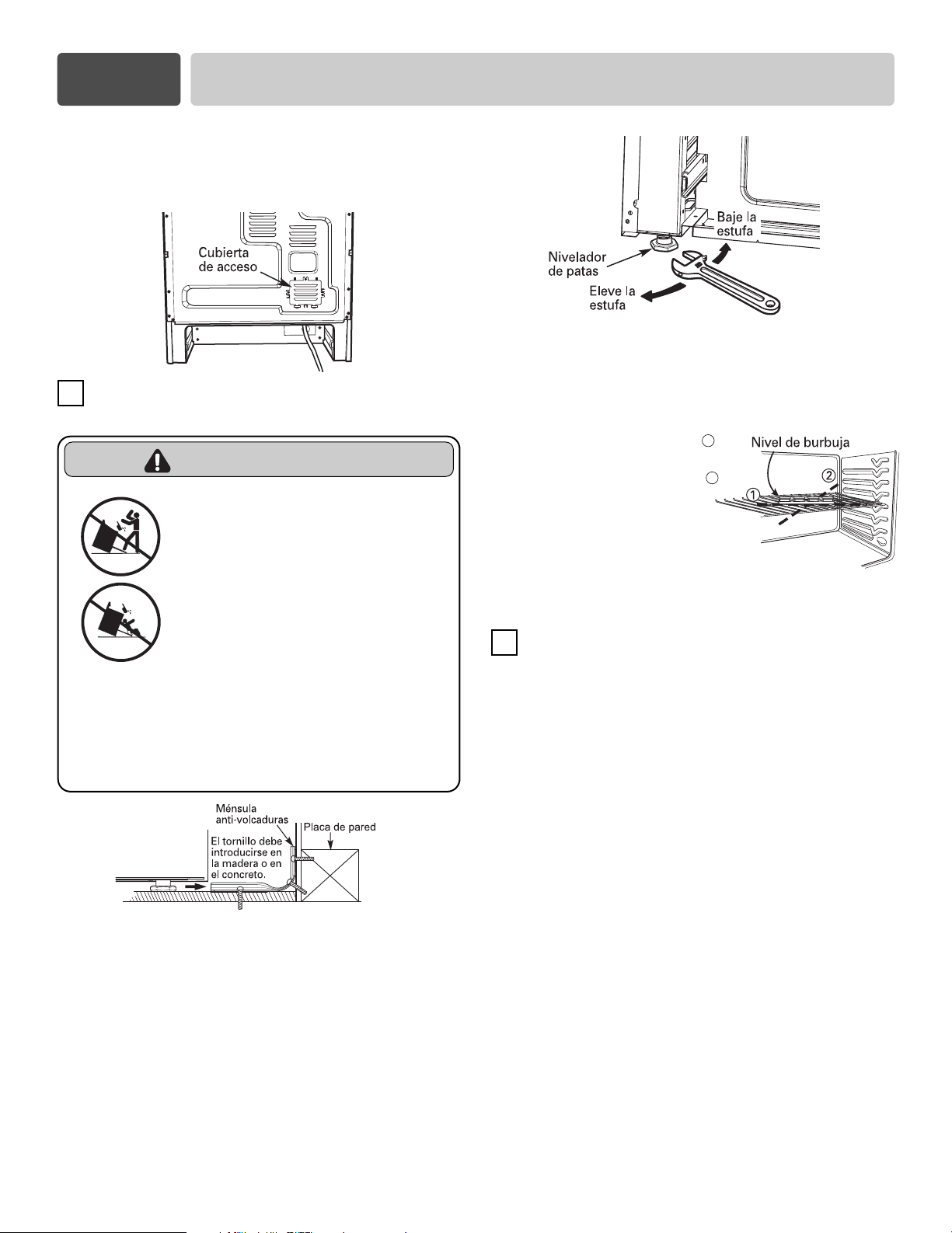
Reponga la cubierta de acceso en la parte posterior de
la estufa. Para reponer la cubierta de alambre, inserte
las salientes dobles en las cavidades ubicadas debajo
de la abertura y apriete los tres tornillos.
INSTALACIÓN DEL DISPOSITIVO
ANTI-VOLCADURAS
1. Ubique la ménsula utilizando la plantilla.
La plantilla viene empacada con cada ménsula anti-
volcaduras. Las instrucciones incluyen la
información necesaria para llevar a buen término la
instalación.
Lea y obedezca el contenido de la hoja de
instrucciones (plantilla) de la estufa.
2. Nivele la estufa
Nivele la estufa ajustando las patas niveladoras con
una llave de tuercas.
9
Utilice un nivel de burbuja para verificar sus ajustes.
Coloque el nivel en la parrilla del horno de la estufa en
forma diagonal y verifique el nivel en cada dirección.
Primero verifique la dirección 1
.
Después verifique la dirección
2
.
Si el nivel de burbuja no
muestra que la parrilla está
nivelada, ajuste las patas
niveladoras con una llave de tuercas.
INSTALACIÓN FINAL
• Acerque la estufa lo suficiente a la abertura para
poder enchufarla en el tomacorriente.
• Acomode la estufa en su puesto cerciorándose de
que la pata posterior izquierda se desliza debajo de
la ménsula anti-volcaduras. Una vez que esté
instalada correctamente, la estufa quedará a 0” de
distancia de la pared trasera.
• Con cuidado, incline la estufa hacia adelante para
comprobar que la ménsula anti-volcaduras
engancha con el tirante posterior de la estufa e
impide que la estufa se vuelque.
• Encienda la alimentación de energía eléctrica.
Verifique que la estufa está orientada correctamente
tal como se describe en el manual del propietario.
5
6
Sección 4
CÓMO INSTALAR LA ESTUFA
• NO se pare o siente en la
puerta del horno. Instale el
soporte anti-volcaduras
incluido con la cocina.
- La cocina puede volcarse y puede
provocar lesiones debido al derrame
de líquidos y alimentos calientes o la
cocina misma.
- Cuando se jala la estufa de la pared
por motivos de limpieza, servicio u
otra razón, asegúrese de volver a
embonar correctamente el
Dispositivo Antivolcadura al volver a
empujar la estufacontra la pared.
ADVERTENCIA


