Loading ...
Loading ...
Loading ...
4. IF THE HOOD IS TO BE “BACK VENTED”, PROCEED DIRECTLY TO STEP 5.
Consult the connection diagrams (following) for further details on exhaust outlet placement.
Method 1: Install the duct(s) from the outside of the home down to the location of the exhaust
outlet(s) on the top of the hood or to the transition (if applicable).
• If a transition is used, install duct down to the location of the transition outlet plus 1”.
This will allow the transition to engage 1” inside of duct.
Method 2: Install the duct(s) from the outside of the home to the ceiling over the exhaust
outlet(s) on the hood. The end of the duct(s) should extend 1” below the ceiling.
• Use foil HVAC tape (not grey cloth duct tape) to seal all joints. See “VENT ACCESSORIES” on
page18 for a listing of available Hestan ducting materials.
TRANSITION HEIGHTS:TRANSITION HEIGHTS:
Dual Blower (WM2L = 600 CFM): none - 8” round duct will connect directly to the top of the
hood.
Single and Dual Blower (WM1L + WM2L = 900 CFM): 6” round duct will connect directly to the
top of the hood; 8” round will connect directly to the top of the hood.
If using the optional multi-blower transition (AKVT6810, sold seperately), a 10”
round duct connects to it 17-1/2” above top of hood. See “VENT ACCESSORIES” on
page18 for details.
Two Dual Blowers (Two WM2Ls = 1200 CFM):
Two 8” round ducts connect directly to the top of the hood.
If using the optional multi-blower transition (AKVT8812, sold seperately), a 12” round
duct connects to it 16-1/2” above top of hood.
See “VENT ACCESSORIES” on page18 for details.
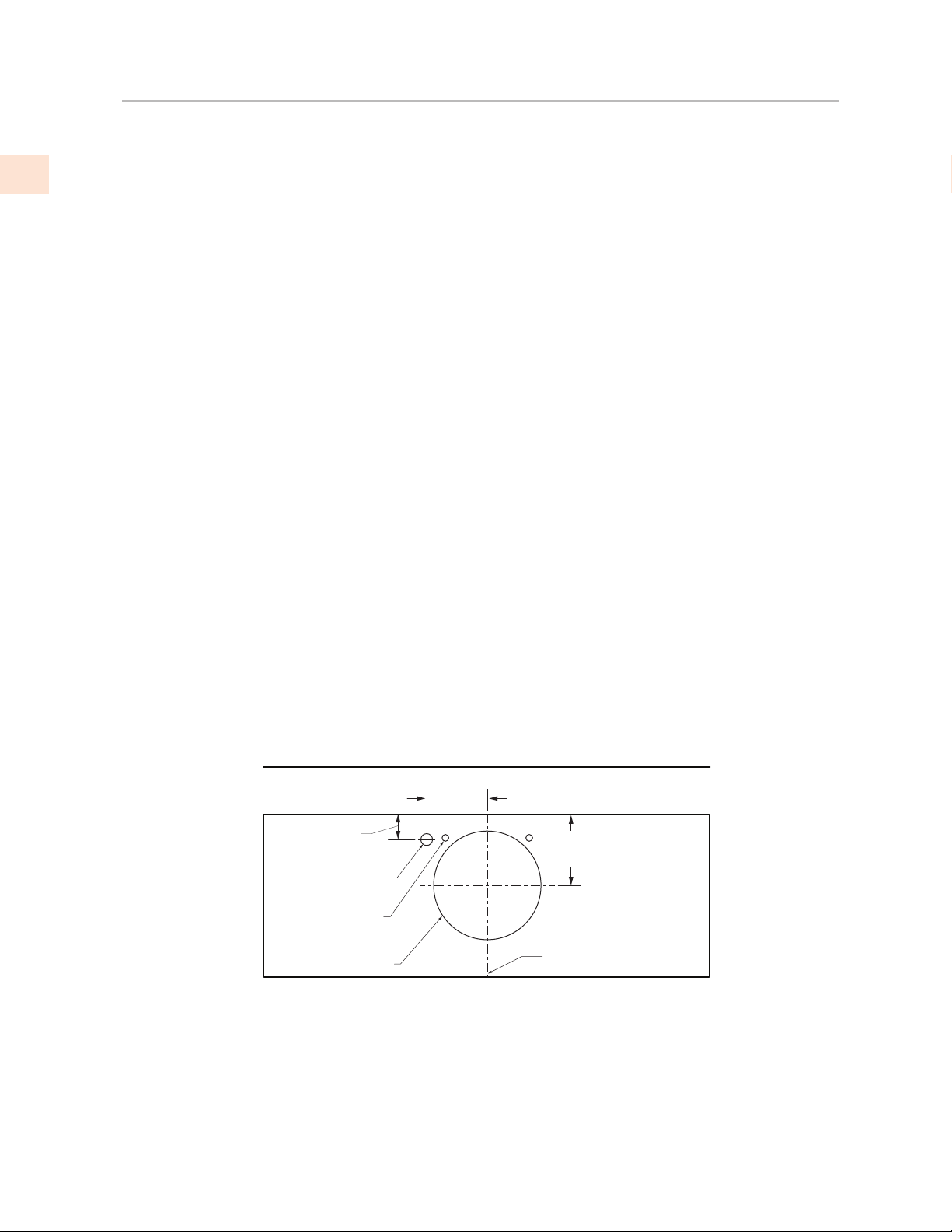
CONNECTION DIAGRAMS CONNECTION DIAGRAMS
Motor
Cooling
Vent (2)
Electrical
WM2L Dual Blower (600 CFM ) (Top View)
(Wall Side)
Centerline
of Hood
Connection Diagram (30-36” width)
8" [20.3 cm] Round
5-1/2"
[14 cm]
1-3/4"
[4.4 cm]
5-1/4"
[13.3 cm]
INSTALLATION
(CONT.)
©2020 Hestan Commercial Corporation
12
EN
Loading ...
Loading ...
Loading ...