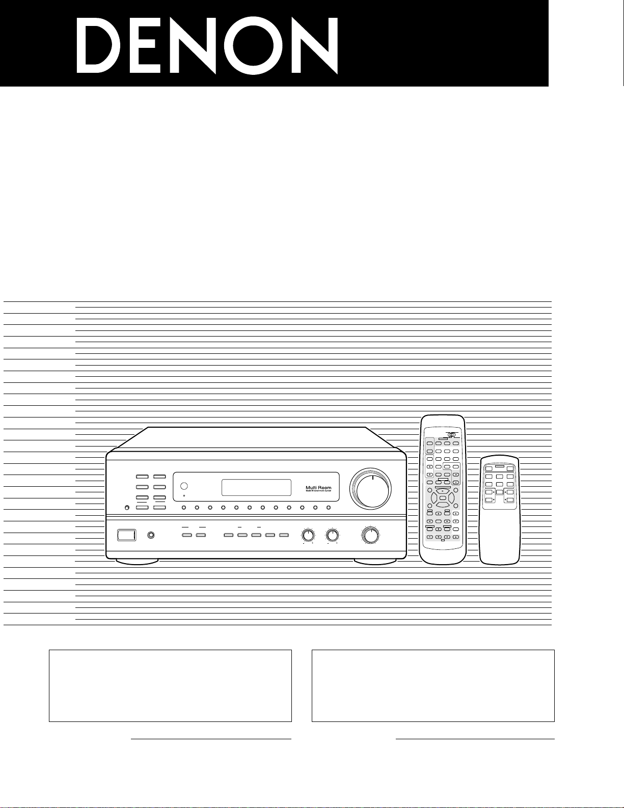
AM-FM STEREO RECEIVER
DRA
-
685
OPERATING INSTRUCTIONS
MODE D’EMPLOI
98
B
CD DVD/VDP
VCR
V.AUX
TUNER
SHIFT
REMOTE CONTROL UNIT RC-872
VOLUME
CHANNEL
DISPLAY
MUTING
VOLUME
TITLE
DISC SKIP+
MULTI
MULTI
VOL.
TAPE
MONITOR
CD·MD/CDR·DVD/ VDP
TV
SET UP
SELECT
MENU
CHANNEL
ON
OFF
RECEIVER
DVD/VDP
TV VCR
PHONO
0
0
2
2
3
AUDIO
CD
MD/CD-R
VIDEO
POWER
DECK
·
VCR
6
7
6
7
VIDEO SELECT
SP-A SP-B
STATUS
RETURN
VOLUME
MODEBAND SHIFTMEMORY 12345678
ON / STANDBY
REMOTE
SENSOR
B
PHONES
ON / STANDBY
BALANCE
MULTI SOURCE
LOUDNESS
MODE
SELECT
VIDEO
SELECT
A
B
TONE
DEFEAT
SPEAKER
BASS TREBLE
LR
DRA-685
PRECISION AUDIO COMPONENT / AM-FM STEREO RECEIVER
TUNING
UPDOWN
PHONO
TUNER
VCR
CD
DVD / VDP
V. AUX
TAPE
MONITOR
AUTO
TUNER
.
B
MULTI SOURCE REMOTE CONTROL UNIT
RC-873
POWER
PHONO CD
DVD/VDP
OFF
ON
VCR V.AUX
TUNER
PRESET VOLUME
TAPE
MONITOR
“SERIAL NO.
PLEASE RECORD UNIT SERIAL NUMBER ATTACHED TO
THE REAR OF THE CABINET FOR FUTURE REFERENCE”
2 We greatly appreciate your purchase of this unit.
2 To be sure you take maximum advantage of all the
features this unit has to offer, read these instructions
carefully and use the set properly. Be sure to keep this
manual for future reference should any questions or
problems arise.
“NO. DE SERIE
PRIERE DE NOTER LE NUMERO DE SERIE DE L’APPAREIL
INSCRIT A L’ARRIERE DU COFFRET DE FAÇON A POUVOIR LE
CONSULTER EN CAS DE PROBLEME.”
2 Nous vous remercions pour l’achat de cet appareil.
2 Pour être sûr de profiter au maximum de toutes les
caractéristiques qu’offre cet appareil, lire avec soin ces
instructions et bien utiliser l’appareil. Toujours
conserver ce mode d’emploi pour s’y référer
ultérieurement en cas de question ou de problème.
FOR ENGLISH READERS PAGE 02 ~ PAGE 29 POUR LES LECTEURS FRANCAIS PAGE 2, 30 ~ PAGE 55
2
2
SAFETY PRECAUTIONS
This device complies with Part 15 of the FCC Rules. Operation is
subject to the following two conditions: (1) This device may not
cause harmful interference, and (2) this device must accept any
interference received, including interference that may cause
undesired operation.
This Class B digital apparatus meets all requirements of the
Canadian Interference-Causing Equipment Regulations.
Cet appareil numérique de la classe B respecte toutes les
exigences du Règlement sur le matériel brouilleur du Canada.
2
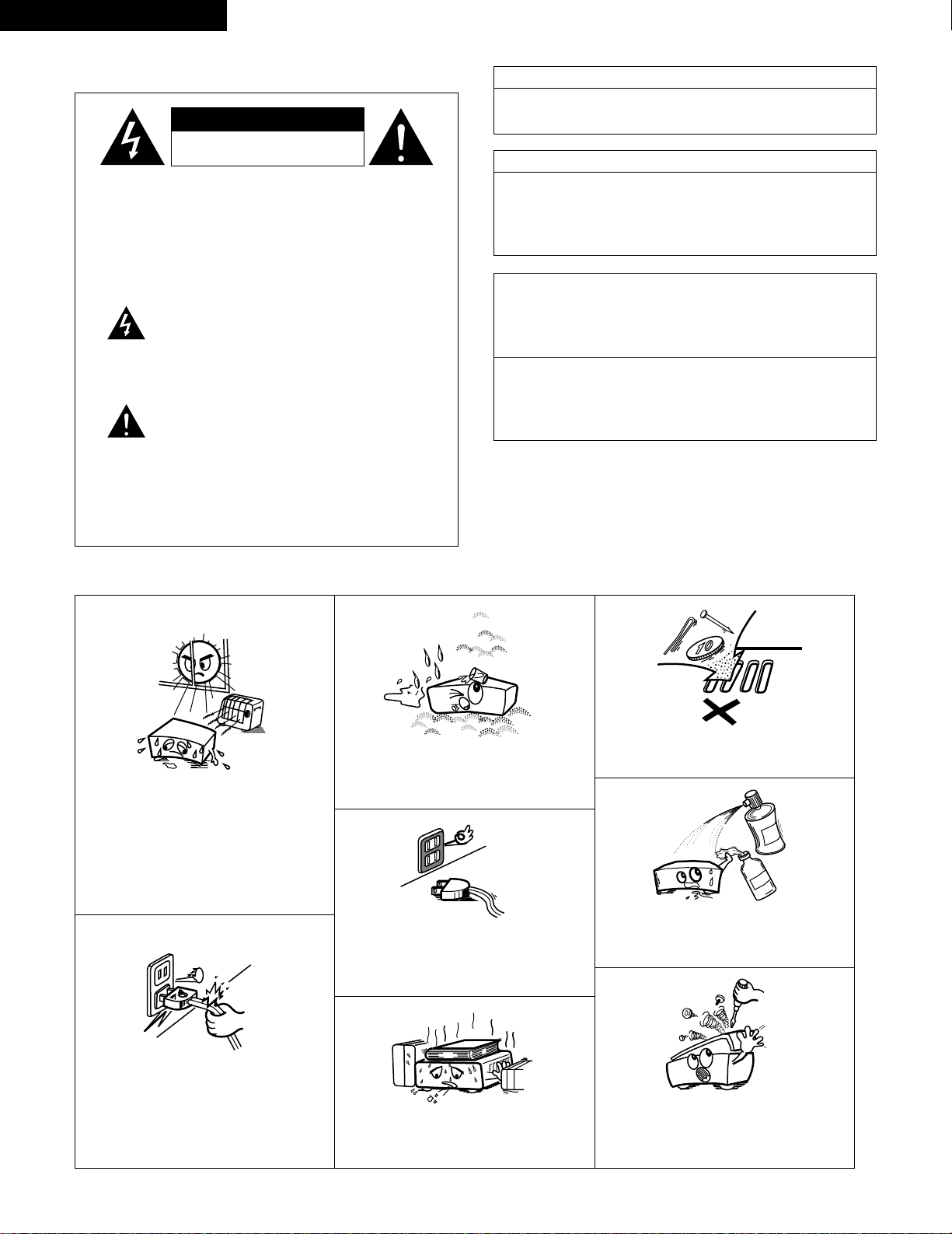
NOTE ON USE / OBSERVATIONS RELATIVES A L’UTILISATION
• Avoid high temperatures.
Allow for sufficient heat dispersion when
installed on a rack.
• Eviter des températures élevées
Tenir compte d’une dispersion de chaleur
suffisante lors de l’installation sur une étagère.
• Keep the set free from moisture, water, and
dust.
• Protéger l’appareil contre l’humidité, l’eau et la
poussière.
• Do not let foreign objects in the set.
• Ne pas laisser des objets étrangers dans
l’appareil.
• Do not let insecticides, benzene, and thinner
come in contact with the set.
• Ne pas mettre en contact des insecticides, du
benzène et un diluant avec l’appareil.
• Never disassemble or modify the set in any
way.
• Ne jamais démonter ou modifier l’appareil
d’une manière ou d’une autre.
• Unplug the power cord when not using the set
for long periods of time.
• Débrancher le cordon d’alimentation lorsque
l’appareil n’est pas utilisé pendant de longues
périodes.
* (For sets with ventilation holes)
• Do not obstruct the ventilation holes.
• Ne pas obstruer les trous d’aération.
• Handle the power cord carefully.
Hold the plug when unplugging the cord.
• Manipuler le cordon d’alimentation avec
précaution.
Tenir la prise lors du débranchement du
cordon.
CAUTION
RISK OF ELECTRIC SHOCK
DO NOT OPEN
CAUTION:
REDUCE THE RISK OF ELECTRIC
SHOCK, DO NOT REMOVE COVER (OR
BACK). NO USER-SERVICEABLE PARTS
INSIDE. REFER SERVICING TO
QUALIFIED SERVICE PERSONNEL.
The lightning flash with arrowhead symbol,
within an equilateral triangle, is intended to alert
the user to the presence of uninsulated
“dangerous voltage” within the product’s
enclosure that may be of sufficient magnitude to
constitute a risk of electric shock to persons.
The exclamation point within an equilateral
triangle is intended to alert the user to the
presence of important operating and
maintenance (servicing) instructions in the
literature accompanying the appliance.
WARNING: TO REDUCE THE RISK OF FIRE OR
ELECTRIC SHOCK, DO NOT EXPOSE
THIS APPLIANCE TO RAIN OR
MOISTURE.
ENGLISH FRANCAIS
CAUTION
TO PREVENT ELECTRIC SHOCK, MATCH WIDE BLADE OF
PLUG TO WIDE SLOT, FULLY INSERT.
ATTENTION
POUR ÉVITER LES CHOCS ÉLECTRIQUES, INTERODUIRE LA
LAME LA PLUS LARGE DE LA FICHE DANS LA BORNE
CORRESPONDANTE DE LA PRISE ET POUSSER JUSQU’ AU
FOND.
3
SAFETY INSTRUCTIONS
1. Read Instructions – All the safety and operating instructions
should be read before the product is operated.
2. Retain Instructions – The safety and operating instructions
should be retained for future reference.
3. Heed Warnings – All warnings on the product and in the
operating instructions should be adhered to.
4. Follow Instructions – All operating and use instructions should
be followed.
5. Cleaning – Unplug this product from the wall outlet before
cleaning. Do not use liquid cleaners or aerosol cleaners.
6. Attachments – Do not use attachments not recommended by
the product manufacturer as they may cause hazards.
7. Water and Moisture – Do not use this product near water – for
example, near a bath tub, wash bowl, kitchen sink, or laundry
tub; in a wet basement; or near a swimming pool; and the like.
8. Accessories – Do not place this product on an unstable cart,
stand, tripod, bracket, or table. The product may fall, causing
serious injury to a child or adult, and serious damage to the
product. Use only with a cart, stand, tripod, bracket, or table
recommended by the manufacturer, or sold with the product.
Any mounting of the product should follow the manufacturer’s
instructions, and should use a
mounting accessory
recommended by the
manufacturer.
9. A product and cart
combination should be
moved with care. Quick
stops, excessive force,
and uneven surfaces may
cause the product and cart
combination to overturn.
10. Ventilation – Slots and openings in the cabinet are provided for
ventilation and to ensure reliable operation of the product and
to protect it from overheating, and these openings must not be
blocked or covered. The openings should never be blocked by
placing the product on a bed, sofa, rug, or other similar
surface. This product should not be placed in a built-in
installation such as a bookcase or rack unless proper
ventilation is provided or the manufacturer’s instructions have
been adhered to.
11. Power Sources – This product should be operated only from
the type of power source indicated on the marking label. If
you are not sure of the type of power supply to your home,
consult your product dealer or local power company. For
products intended to operate from battery power, or other
sources, refer to the operating instructions.
12. Grounding or Polarization – This product may be equipped with
a polarized alternating-current line plug (a plug having one
blade wider than the other). This plug will fit into the power
outlet only one way. This is a safety feature. If you are unable
to insert the plug fully into the outlet, try reversing the plug. If
the plug should still fail to fit, contact your electrician to replace
your obsolete outlet. Do not defeat the safety purpose of the
polarized plug.
13. Power-Cord Protection – Power-supply cords should be routed
so that they are not likely to be walked on or pinched by items
placed upon or against them, paying particular attention to
cords at plugs, convenience receptacles, and the point where
they exit from the product.
15. Outdoor Antenna Grounding – If an outside antenna or cable
system is connected to the product, be sure the antenna or
cable system is grounded so as to provide some protection
against voltage surges and built-up static charges. Article 810
of the National Electrical Code, ANSI/NFPA 70, provides
information with regard to proper grounding of the mast and
supporting structure, grounding of the lead-in wire to an
antenna discharge unit, size of grounding conductors, location
of antenna-discharge unit, connection to grounding electrodes,
and requirements for the grounding electrode. See Figure A.
16. Lightning – For added protection for this product during a
lightning storm, or when it is left unattended and unused for
long periods of time, unplug it from the wall outlet and
disconnect the antenna or cable system. This will prevent
damage to the product due to lightning and power-line surges.
17. Power Lines – An outside antenna system should not be
located in the vicinity of overhead power lines or other electric
light or power circuits, or where it can fall into such power
lines or circuits. When installing an outside antenna system,
extreme care should be taken to keep from touching such
power lines or circuits as contact with them might be fatal.
18. Overloading – Do not overload wall outlets, extension cords, or
integral convenience receptacles as this can result in a risk of
fire or electric shock.
19. Object and Liquid Entry – Never push objects of any kind into
this product through openings as they may touch dangerous
voltage points or short-out parts that could result in a fire or
electric shock. Never spill liquid of any kind on the product.
20.
Servicing – Do not attempt to service this product yourself
as opening or removing covers may expose you to
dangerous voltage or other hazards. Refer all servicing to
qualified service personnel.
21.
Damage Requiring Service – Unplug this product from the
wall outlet and refer servicing to qualified service
personnel
under the following conditions:
a) When the power-supply cord or plug is damaged,
b) If liquid has been spilled, or objects have fallen into the
product,
c) If the product has been exposed to rain or water,
d) If the product does not operate normally by following the
operating instructions. Adjust only those controls that are
covered by the operating instructions as an improper
adjustment of other controls may result in damage and will
often require extensive work by a qualified technician to
restore the product to its normal operation,
e) If the product has been dropped or damaged in any way,
and
f) When the product exhibits a distinct change in performance
– this indicates a need for service.
22. Replacement Parts – When replacement parts are required, be
sure the service technician has used replacement parts
specified by the manufacturer or have the same characteristics
as the original part. Unauthorized substitutions may result in
fire, electric shock, or other hazards.
23. Safety Check – Upon completion of any service or repairs to
this product, ask the service technician to perform safety
checks to determine that the product is in proper operating
condition.
24. Wall or Ceiling Mounting – The product should be mounted to
a wall or ceiling only as recommended by the manufacturer.
25. Heat – The product should be situated away from heat sources
such as radiators, heat registers, stoves, or other products
(including amplifiers) that produce heat.
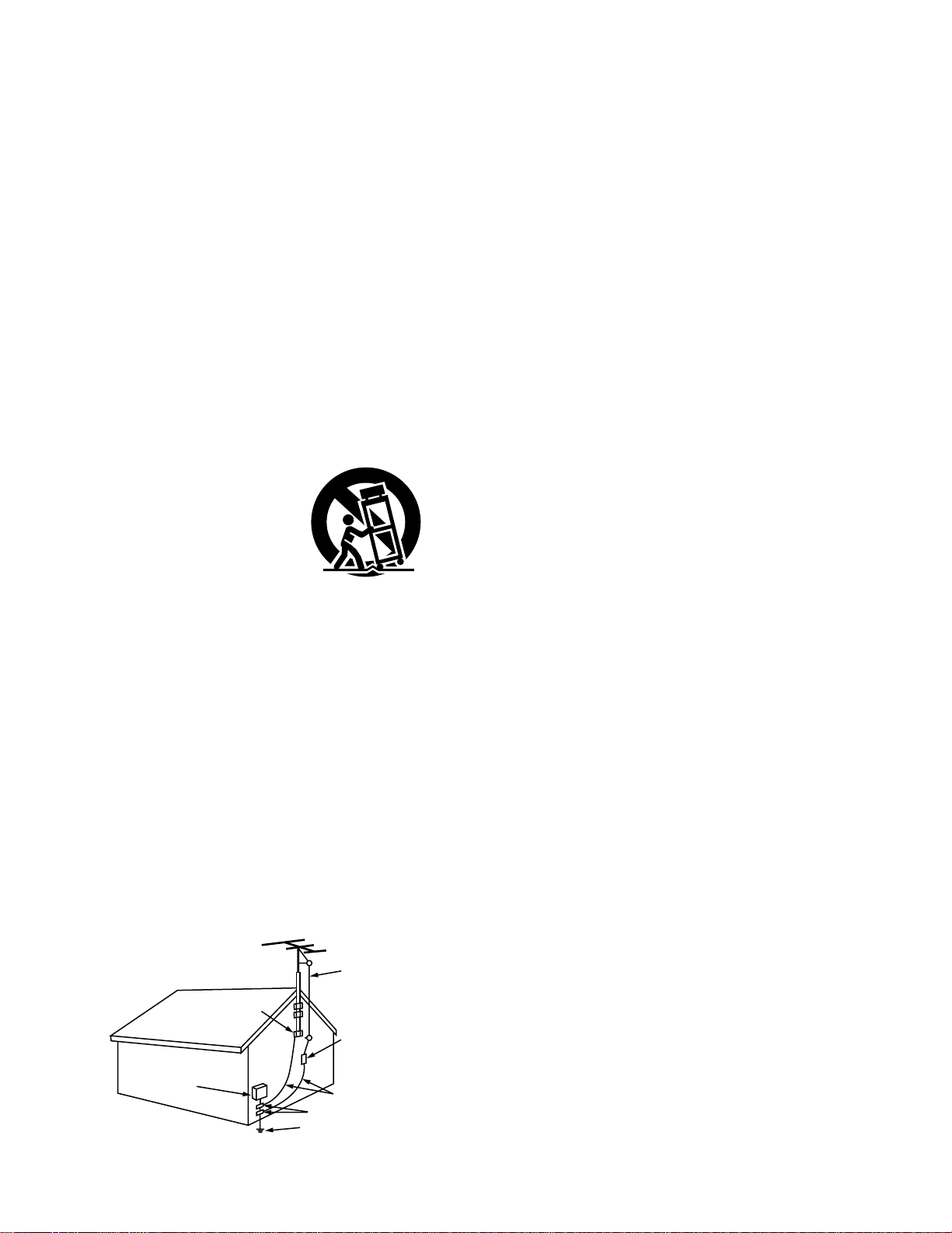
FIGURE A
EXAMPLE OF ANTENNA GROUNDING
AS PER NATIONAL
ELECTRICAL CODE
ANTENNA
LEAD IN
WIRE
GROUND
CLAMP
ELECTRIC
SERVICE
EQUIPMENT
ANTENNA
DISCHARGE UNIT
(NEC SECTION 810-20)
GROUNDING CONDUCTORS
(NEC SECTION 810-21)
GROUND CLAMPS
POWER SERVICE GROUNDING
ELECTRODE SYSTEM
(NEC ART 250, PART H)
NEC - NATIONAL ELECTRICAL CODE
4
ENGLISH
TABLE OF CONTENTS
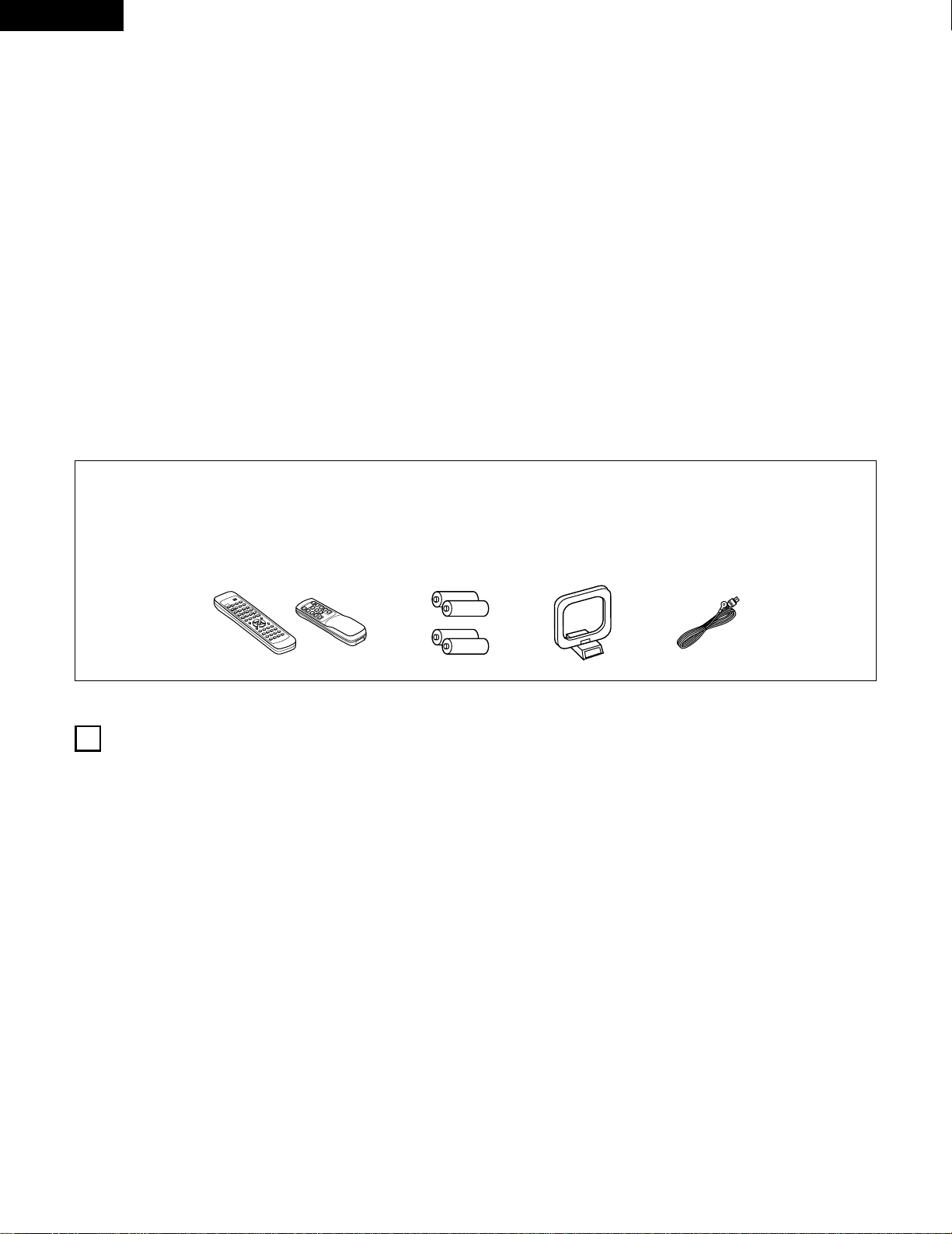
2 ACCESSORIES
Check that the following parts are included in addition to the main unit:
r
9
8
B
0
0
2
2
3
6
7
6
7
t yu
B
z
Before Using …………………………………………………………4
x
Cautions on Installation ………………………………………………5
c
Cautions on Handling…………………………………………………5
v
Features ………………………………………………………………5
b
Connections ………………………………………………………6~10
n
Part Names and Functions ……………………………………10, 11
m
Remote Control Unit……………………………………………12~17
,
Operations ………………………………………………………17~23
.
Listening to the Radio …………………………………………24~26
⁄0
Initialization of the Microprocessor ………………………………27
⁄1
Last function memory ………………………………………………27
⁄2
Troubleshooting ……………………………………………………28
⁄3
Specifications ………………………………………………………29
2
INTRODUCTION
Thank you for choosing the DENON AM-FM Stereo receiver. This remarkable component has been engineered to provide outstanding high
fidelity reproduction of your favorite music sources.
As this product is provided with an immense array of features, we recommend that before you begin hookup and operation that you review the
contents of this manual before proceeding.
1
BEFORE USING
Pay attention to the following before using this unit:
• Moving the set
To prevent short circuits or damaged wires in the connection
cords, always unplug the power cord and disconnect the
connection cords between all other audio components when
moving the set.
• Before turning the power operation switch on
Check once again that all connections are proper and that there are
not problems with the connection cords. Always set the power
operation switch to the standby position before connecting and
disconnecting connection cords.
• Store this instructions in a safe place.
After reading, store this instructions along with the warranty in a
safe place.
• Note that the illustrations in this instructions may differ from
the actual set for explanation purposes.
q
Operating instructions
……………………………………………1
w
Warranty
……………………………………………………………1
e
Service station list
…………………………………………………1
r
Remote control unit (RC-872)
……………………………………1
(RC-873
)
……………………………………1
t
Batteries (R6P/AA) …………………………………………………2
(R03/AAA) ………………………………………………2
y
AM loop antenna …………………………………………………1
u
FM indoor antenna…………………………………………………1
(RC-872) (RC-873)
5
ENGLISH
2
CAUTIONS ON INSTALLATION
3
CAUTIONS ON HANDLING
Noise or disturbance of the picture may be generated if this unit or
any other electronic equipment using microprocessors is used near a
tuner or TV.
If this happens, take the following steps:
• Install this unit as far as possible from the tuner or TV.
• Set the antenna wires from the tuner or TV away from this unit’s
power cord and input/output connection cords.
• Noise or disturbance tends to occur particularly when using indoor
antennas or 300 Ω/ohms feeder wires. We recommend using
outdoor antennas and 75 Ω/ohms coaxial cables.
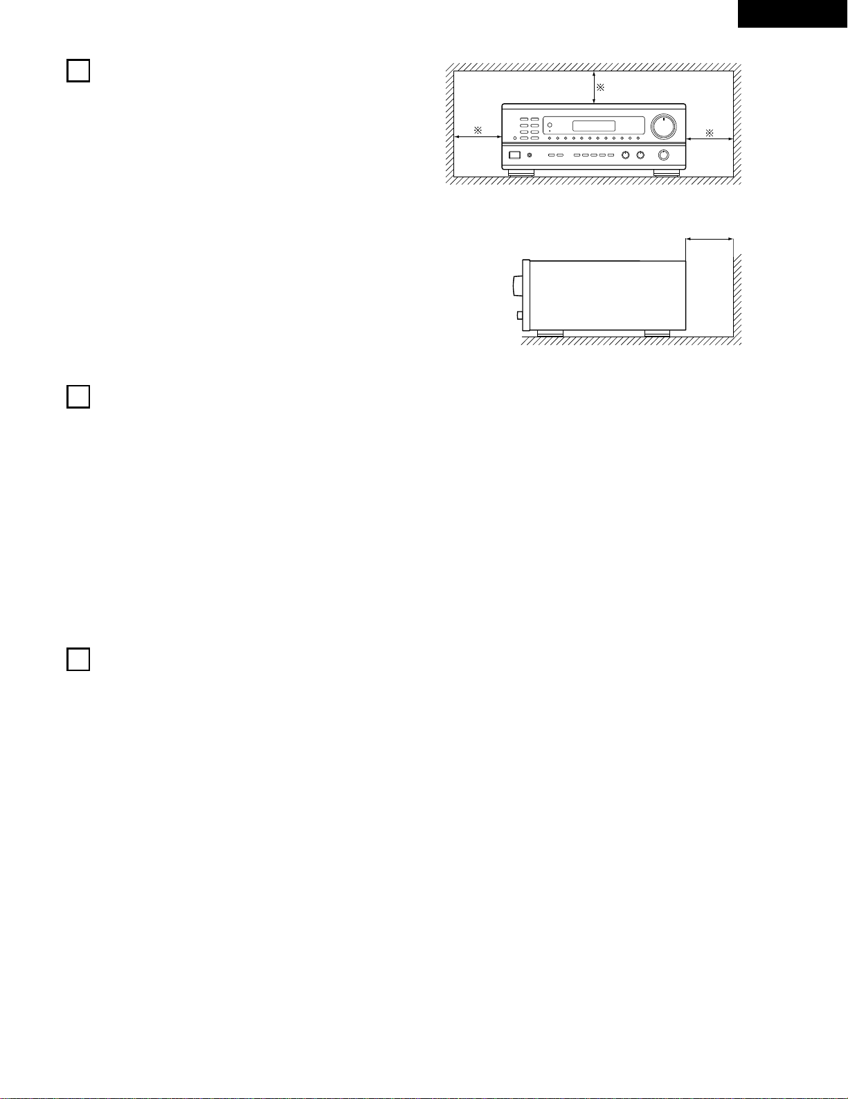
For heat dispersal, leave at least 10 cm of space between the
top, back and sides of this unit and the wall or other compo-
nents.
• Switching the input function when input jacks are not
connected
A clicking noise may be produced if the input function is switched
when nothing is connected to the input jacks. If this happens,
either turn down the VOLUME control or connect components to
the input jacks.
• Muting of PRE OUT jacks
The PRE OUT jacks include a muting circuit. Because of this, the
output signals are greatly reduced for several seconds after the
power operation switch is turned on.
If the volume is turned up during this time, the output will be very
high after the muting circuit stops functioning. Always wait until
the muting circuit turns off before adjusting the volume.
• Whenever the power operation switch is in the STANDBY
state, the apparatus is still connected on some AC line
voltages.
Please be sure to unplug the cord when you leave home for,
say, a vacation.
B
10 cm or more
10 cm or more
Wall
4
FEATURES
1. Multi Room Music Entertainment System
Multi Source Function:
This unit’s Multi Source function lets you select different audio
or video sources for viewing or listening Different sources can
thus be enjoyed in the main room and the subroom
simultaneously. This novel feature gives you considerable
flexibility when setting up and enjoying your system with the
this unit. The output level, adjustable by the remote
commander, is as much as 1V, enough to operate the optional
power amplifier placed in a subroom.
2. Powerful, Versatile Amplifier
High-Quality Power Amplifier:
High-speed, high-power transistors employed in a rational
circuit configuration reflect DENON’S advanced amplifier
technology and ensure a very hefty, clean power output.
3. Signal Level Divided Construction (SLDC)
The circuits handling low-level and high-level signals have been
divided into separate blocks to ensure that influences from these
signals on each other are held to an absolute minimum. This
chassis design in the this unit is called the Signal Level Divided
Construction (SLDC). Signals for output are cleaner than before,
allowing them to be reproduced with even greater fidelity and
clarity.
4. Remote Control Functions
• Remote Control unit with pre-memory function (RC-872):
This unit comes with a remote control unit equipped with a
pre-memory function. The remote control command codes for
DENON remote controllable AV components as well as for DVD
players, video decks, TVs, etc., of other major manufacturers
are prestored in the memory.
• Multi Source Remote Control Unit (RC-873):
This unit comes with the Multi Source Remote Control Unit,
which operates the Multi Source Output and commands the
receiver to select the function, recalling preset stations, and
adjust the volume level from a subroom.
6
ENGLISH
L
R
L
R
R LR L
R L
R L
R L
R L
+
-
+
-
SPEAKER SYSTEMS
IMPEDANCE A or B : 4 16 A
+
B : 8 16
VIDEO
PRE OUT
MAIN IN
B A
SWITCHED
TOTAL 120W
(
1A.
)
MAX.
120V 60Hz
AC OUTLETS
AUDIO
AUDIO
OUT
IN
OUT
OUT
IN
OUT
IN
DVD
/
VDP
VCR
MULTI
SOURCE
MULTI
SOURCE
ANTENNA
V.AUX
MONITOR
PHONO
CD
V.AUX
VCR
DVD
/
VDP
TAPE
VCRVCR
TAPE
ROOM TO ROOM
(
REMOTE CONTROL
)
SIGNAL
GND
LOOP
ANT.
AM
FM
COAX.
75
LINE IN
LINE OUT
LINE OUT
R
INPUTOUTPUT
LRL
L
R
L
R
L
R
L
R
R
OUTPUT
L
R
L
++
R
L
INPUT
OUTPUT
AUX OUT
LINE IN
DIGITAL AUDIODIGITAL AUDIO
5
CONNECTIONS
• Do not plug in the power cord until all connections have been
completed.
• Be sure to connect the left and right channels properly (left
with left, right with right).
• Insert the plugs securely. Incomplete connections will result in
the generation of noise.
• Use the AC OUTLETS for audio equipment only. Do not use
them for hair driers, etc.
• Note that binding pin plug cords together with power cords or
placing them near a power transformer will result in generating
hum or other noise.
• If hum or other noise is produced when the ground wire is
connected, disconnect it.
• Noise or humming may be generated if a connected
component is used independently without turning the power of
this unit on. If this happens, turn on the power of the this unit.
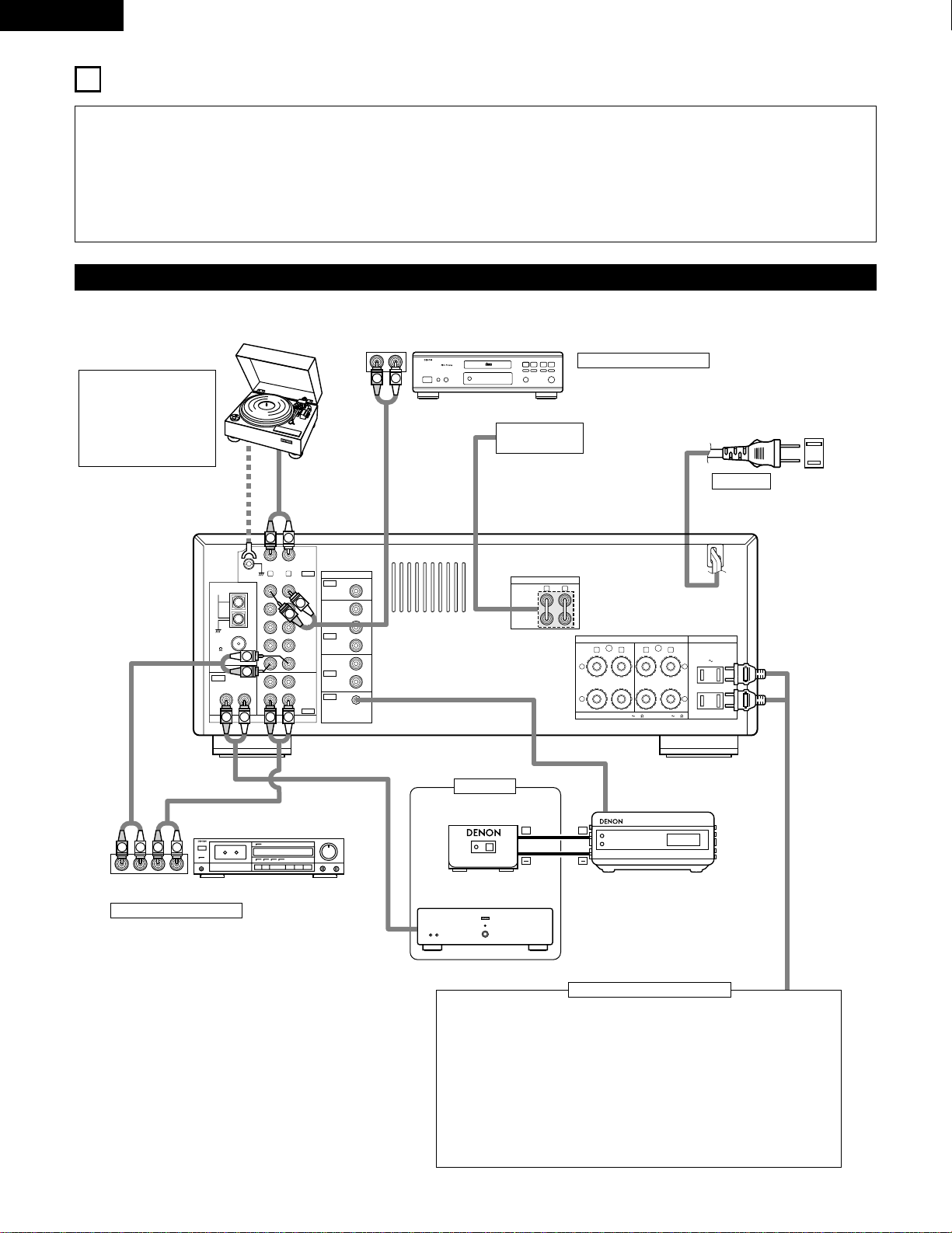
Connecting the audio components
Turntable (MM cartridge)
Ground wire
Tape deck
CD player
NOTE:
This unit cannot be used
with MC cartridges
directly. Use a separate
head amplifier or step-
up transformer.
Connecting a CD player
Connect the CD player’s analog output jacks (ANALOG
OUTPUT) to this unit’s CD jacks using pin plug cords.
Use these jacks when using
another separate amplifier or a
pre-main amplifier.
AC 120 V, 60 Hz
AC OUTLETS
• SWITCHED
(total capacity – 120 W (1 A.)
The power to this outlet is turned on and off in conjunction with the POWER
operation switch on the main unit, and when the power is switched between
on and standby from the remote control unit.
No power is supplied from these outlets when this unit’s power is at standby.
Never connect equipment whose total capacity is above 120 W (1 A.)
NOTE:
Use the AC OUTLETS for audio equipment only. Do not use them for hair
driers, etc.
Connecting the AC OUTLETS
Connecting a tape deck
Connections for recording:
Connect the tape deck’s recording input jacks
(LINE IN or REC) to this unit’s tape recording
(OUT) jacks using pin plug cords.
Connections for playback:
Connect the tape deck’s playback output jacks
(LINE OUT or PB) to this unit’s tape playback
(IN) jacks using pin plug cords.
PRE OUT jacks
MAIN IN jacks
AC CORD
RC-617 (Sold Separately)
Infrared sensor
Power amplifier
RC-616 (Sold Separately)
Infrared retransmitter
Sub room
7
ENGLISH
R LR L
R L
R L
R L
R L
+
-
+
-
SPEAKER SYSTEMS
IMPEDANCE A or B : 4 16 A
+
B : 8 16
VIDEO
PRE OUT
MAIN IN
B A
SWITCHED
TOTAL 120W
(
1A.
)
MAX.
120V 60Hz
AC OUTLETS
AUDIO
AUDIO
OUT
IN
OUT
OUT
IN
OUT
IN
DVD
/
VDP
VCR
MULTI
SOURCE
MULTI
SOURCE
ANTENNA
V.AUX
MONITOR
PHONO
CD
V.AUX
VCR
DVD
/
VDP
TAPE
VCRVCR
TAPE
ROOM TO ROOM
(
REMOTE CONTROL
)
SIGNAL
GND
LOOP
ANT.
AM
FM
COAX.
75
AUDIO OUT
VIDEO OUT
AUDIO IN
AUDIO OUT
VIDEO OUT
VIDEO IN
VIDEO OUT
VIDEO IN
AUDIO OUT
IN
VIDEO
ROUT
VIDEO
OUT
L
AUDIO
L
R
R OUT
VIDEO
OUT
L
AUDIO
R
L
R
L
R
L
L
R
R OUT IN
AUDIO
VIDEO
OUT IN
LRL
R
L
R
L
VIDEO IN
L
R
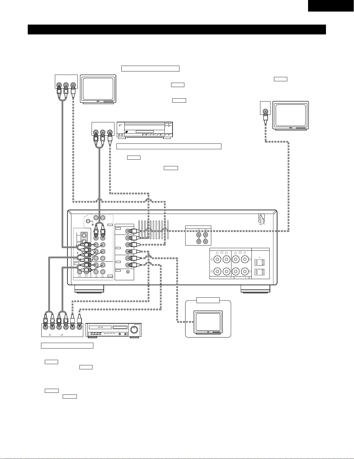
Connecting the video equipments
• To connect the video signal, connect using a 75 Ω/ohms video signal cable cord. Using an improper cable can result in a drop in sound quality.
• When making connections, also refer to the operating instructions of the other components.
Connecting a TV/DBS tuner
TV/DBS
• Connect the TV’s or DBS tuner’s video output jack
(VIDEO OUTPUT) to the (yellow) V.AUX IN jack
using a 75 Ω/ohms video coaxial pin plug cord.
• Connect the TV’s or DBS tuner’s audio output jacks
(AUDIO OUTPUT) to the V.AUX IN jacks using
pin plug cords.
AUDIO
VIDEO
TV or DBS tuner
LD player (VDP) or DVD player
Video deck
Monitor TV
MONITOR OUT
• Connect the TV’s video input jack (VIDEO
INPUT) to the MONITOR OUT jack
using a 75 Ω/ohms video coaxial pin plug
cord.
VIDEO
Connecting a video disc player VDP or a DVD player
• Connect the video disc player’s (DVD player’s) video output jack (VIDEO OUTPUT) to
the (yellow) DVD/VDP IN jack using a 75 Ω/ohms video coaxial pin plug cord.
• Connect the video disc player’s (DVD player’s) analog audio output jacks (ANALOG
AUDIO OUTPUT) to the DVD/VDP IN jacks using pin plug cords.
AUDIO
VIDEO
Connecting a video decks
Video input/output connections:
• Connect the video deck’s video output jack (VIDEO OUT) to the
(yellow) VCR IN jack, and the video deck’s video input jack
(VIDEO IN) to the (yellow) VCR OUT jack using 75 Ω/ohms
video coaxial pin plug cords.
Connecting the audio output jacks
• Connect the video deck audio output jacks (AUDIO OUT) to the
VCR IN jacks, and the video deck’s audio input jacks (AUDIO
IN) to the VCR OUT jacks using pin plug cords.
AUDIO
AUDIO
VIDEO
VIDEO
Monitor TV
Sub room
8
ENGLISH
R L
R L
R L
VIDEO
AUDIO
OUT
IN
OUT
OUT
IN
OUT
IN
DVD
/
VDP
VCR
MULTI
SOURCE
MULTI
SOURCE
ANTENNA
V.AUX
MONITOR
PHONO
CD
V.AUX
VCR
DVD
/
VDP
TAPE
VCRVCR
TAPE
ROOM TO ROOM
(
REMOTE CONTROL
)
SIGNAL
GND
LOOP
ANT.
AM
FM
COAX.
75
Note to CATV system installer:
This reminder is provided to call the CATV system installer’s attention to
Article 820-40 of the NEC which provides guidelines for proper
grounding and, in particular, specifies that the cable ground shall be
connected to the grounding system of the building, as close to the point
of cable entry as practical.
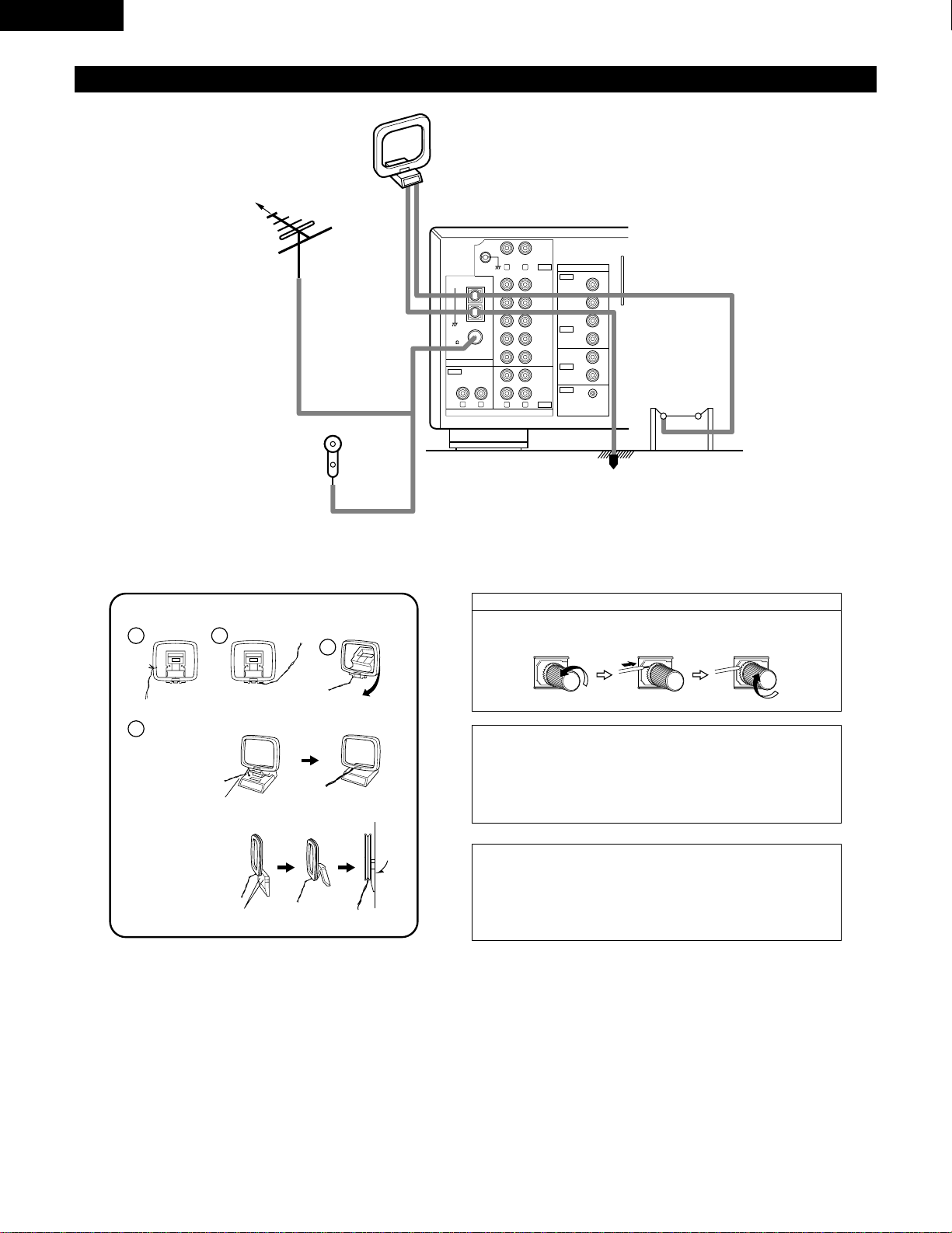
NOTES:
• Do not connect two FM antennas simultaneously.
• Even if an external AM antenna is used, do not disconnect AM loop
antenna.
• Make sure AM loop antenna lead terminals do not touch metal parts of
the panel.
Connecting the antenna terminals
DIRECTION OF
BROADCASTING
STATION
FM ANTENNA
75 Ω/ohms
COAXIAL
CABLE
FM INDOOR ANTENNA
(An Accessory)
AM LOOP
ANTENNA
(An Accessory)
AM OUTDOOR
ANTENNA
Connection of AM antennas
1.
Loosen by turning
counterclockwise.
2. Insert the cord. 3. Tighten by turning
clockwise.
1
4
2
3
AM loop antenna assembly
Connect to the AM
antenna terminals.
Bend in the reverse
direction.
Remove the vinyl
tie and take out the
connection line.
a. With the antenna
on top any stable
surface
b. With the antenna
attach to a wall.
Instllation hole
Mount on wall, etc.
Mount
GROUND
9
ENGLISH
(
L
) (
R
)(
L
) (
R
)
R LR L
R L
R L
R L
R L
+
-
+
-
SPEAKER SYSTEMS
IMPEDANCE A or B : 4 16 A
+
B : 8 16
VIDEO
PRE OUT
MAIN IN
B A
SWITCHED
TOTAL 120W
(
1A.
)
MAX.
120V 60Hz
AC OUTLETS
AUDIO
AUDIO
OUT
IN
OUT
IN
OUT
IN
DVD
/
VDP
VCR
MULTI
SOURCE
MULTI
SOURCE
ANTENNA
V.AUX
MONITOR
PHONO
CD
V.AUX
VCR
DVD
/
VDP
TAPE
VCRVCR
TAPE
ROOM TO ROOM
(
REMOTE CONTROL
)
SIGNAL
GND
LOOP
ANT.
AM
FM
COAX.
75
Speaker system connections
• Connect the speaker terminals with the speakers making sure that
like polarities are matched (
<
with
<
,
>
with
>
). Mismatching of
polarities will result in weak central sound, unclear orientation of
the various instruments, and the sense of direction of the stereo
being impaired.
• When making connections, take care that none of the individual
conductors of the speaker cord come in contact with adjacent
terminals, with other speaker cord conductors, or with the rear
panel.
Speaker Impedance
• When speaker systems A and B are use separately, speakers with
an impedance of 4 to 16 Ω/ohms can be connected for use as
speakers.
• Be careful when using two pairs of speakers (A + B) at the same
time, since use of speakers with an impedance of 8 to 16 Ω/ohms.
• The protector circuit may be activated if the set is played for long
periods of time at high volumes when speakers with an
impedance lower than the specified impedance are connected.
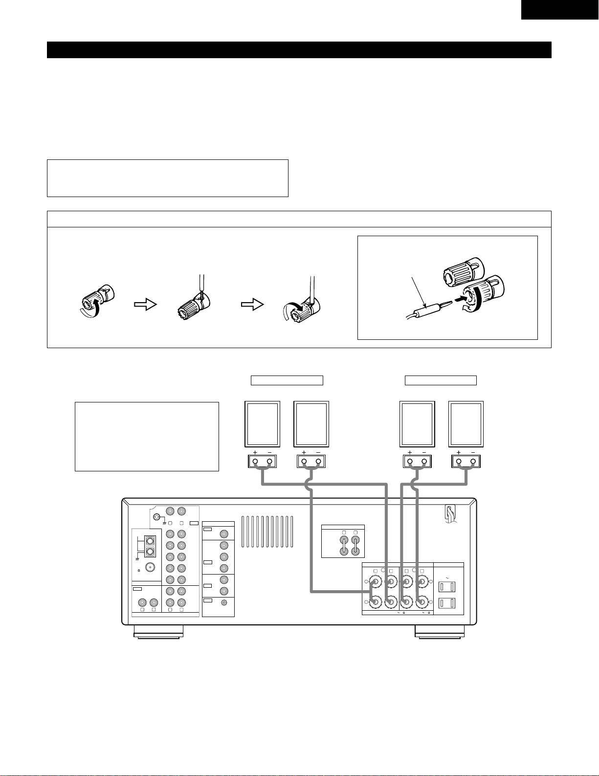
Connecting the speaker terminals
1. Loosen by turning
counterclockwise.
2. Insert the cord. 3. Tighten by turning
clockwise.
Connecting banana plugs
banana plug
Turn clockwise to tighten, then insert the banana plug.
• Precautions when connecting speakers
If a speaker is placed near a TV or video
monitor, the colors on the screen may be
disturbed by the speaker’s magnetism. If
this should happen, move the speaker
away to a position where it does not have
this effect.
NOTE:
NEVER touch the speaker terminals when the power is on.
Doing so could result in electric shocks.
System B
SPEAKER SYSTEMS
System A
SPEAKER SYSTEMS
10
ENGLISH
Protector circuit
•
This unit is equipped with a high-speed protection circuit. This circuit protects the internal circuitry from damage due to
large currents flowing if the speaker jacks are not completely connected or if an output is generated by a short circuit.
In such a case, the protection circuit will operate to cut off the output to the speakers. Should this happen, turn the
power off and check the speaker connections. Then turn the power on again. After muting for several seconds, the
receiver should be operating normally.
If the protection circuit is activated again even though there are no problems with the wiring or the ventilation around
the unit, switch off the power and contact a DENON service center.
Note on speaker impedance
•
The protector circuit may be activated if the set is played for long periods of time at high volumes when speakers with
an impedance lower than the specified impedance (for example speakers with an impedance of lower than 4 Ω/ohms)
are connected. If the protector circuit is activated, the speaker output is cut off. Turn off the set’s power, wait for the set
to cool down, improve the ventilation around the set, then turn the power back on.
6
PART NAMES AND FUNCTIONS
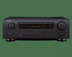
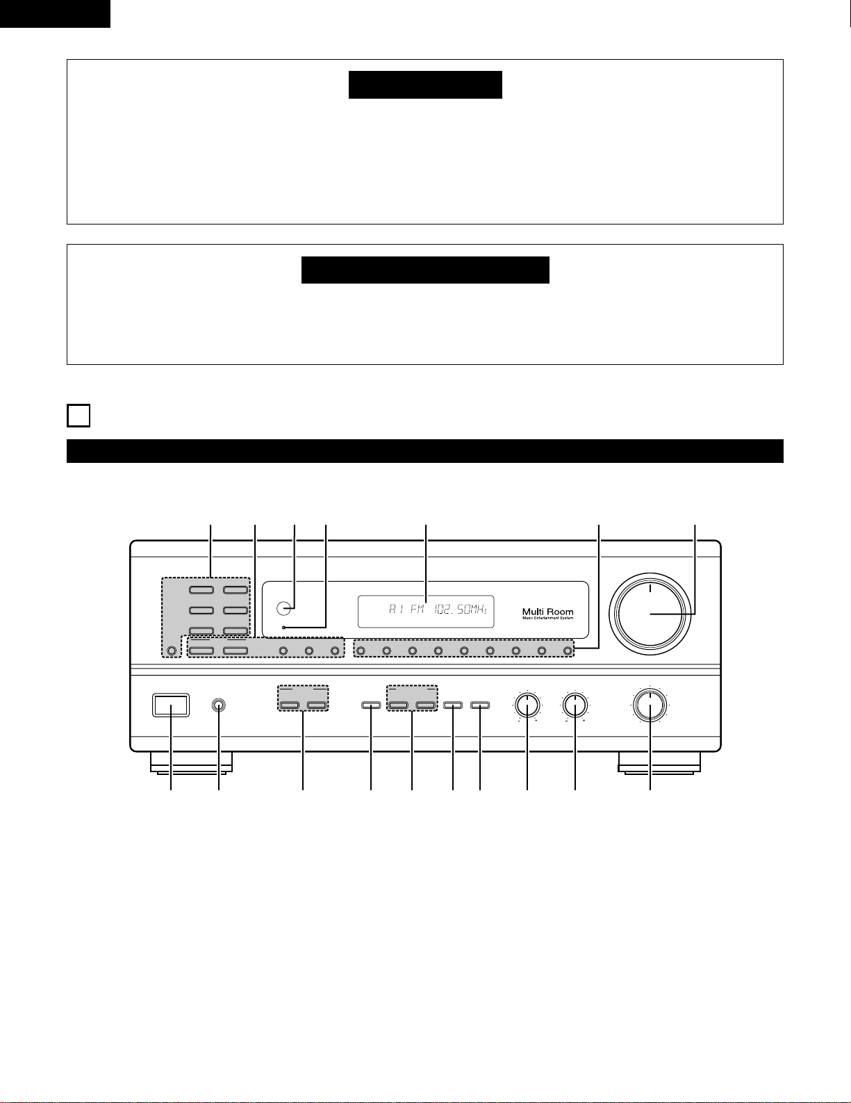
Front Panel
• For details on the functions of these parts, refer to the pages given in parentheses ( ).
VOLUME
MODEBAND SHIFTMEMORY 12345678
STANDBY
REMOTE
SENSOR
B
PHONES
ON / STANDBY
BALANCE
MULTI SOURCE
LOUDNESS
MODE
SELECT
VIDEO
SELECT
A
B
TONE
DEFEAT
SPEAKER
BASS TREBLE
LR
DRA-685
PRECISION AUDIO COMPONENT / AM-FM STEREO RECEIVER
TUNING
UPDOWN
PHONO
TUNER
VCR
CD
DVD / VDP
V. AUX
TAPE
MONITOR
!7 !6 !5
!4
!3
!1!2
!0oiuytrewq
AUTO CH
TONE SP-A TUNER
q
Power operation switch …………………………………………(17)
w
Headphone jacks (PHONES) ……………………………………(22)
e
SPEAKER A/B buttons……………………………………………(17)
r
VIDEO SELECT button …………………………………………(22)
t
MULTI SOURCE buttons ……………………………………(19, 20)
y
TONE DEFECT button ……………………………………………(18)
u
LOUDNESS button ………………………………………………(18)
i
BASS adjustment control ………………………………………(18)
o
TREBLE adjustment control ……………………………………(18)
!0
BALANCE control …………………………………………………(18)
!1
VOLUME control …………………………………………………(18)
!2
Preset memory selector buttons ………………………………(26)
!3
Display
!4
Power indicator……………………………………………………(17)
!5
Remote control sensor (REMOTE SENSOR) …………………(12)
!6
TUNING buttons ……………………………………………(25, 26)
!7
Input source selector buttons …………………………………(18)
11
ENGLISH
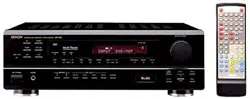
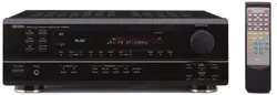
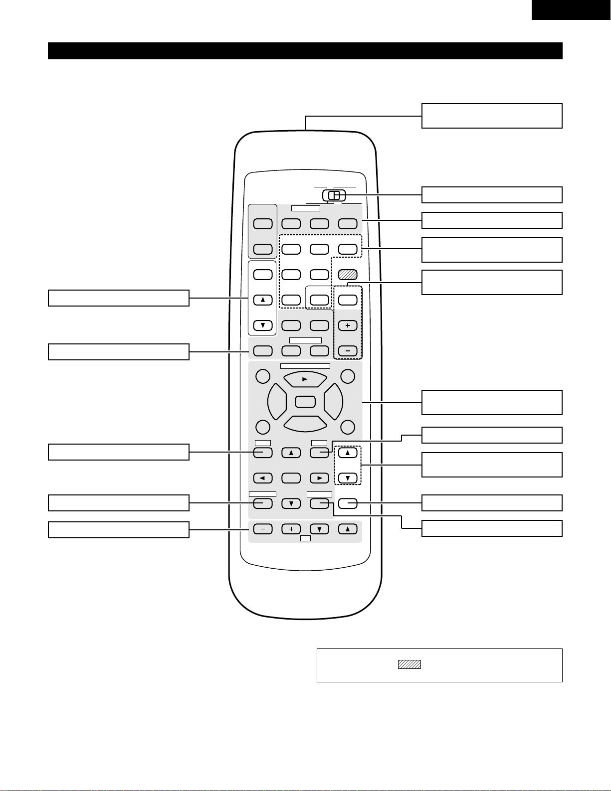
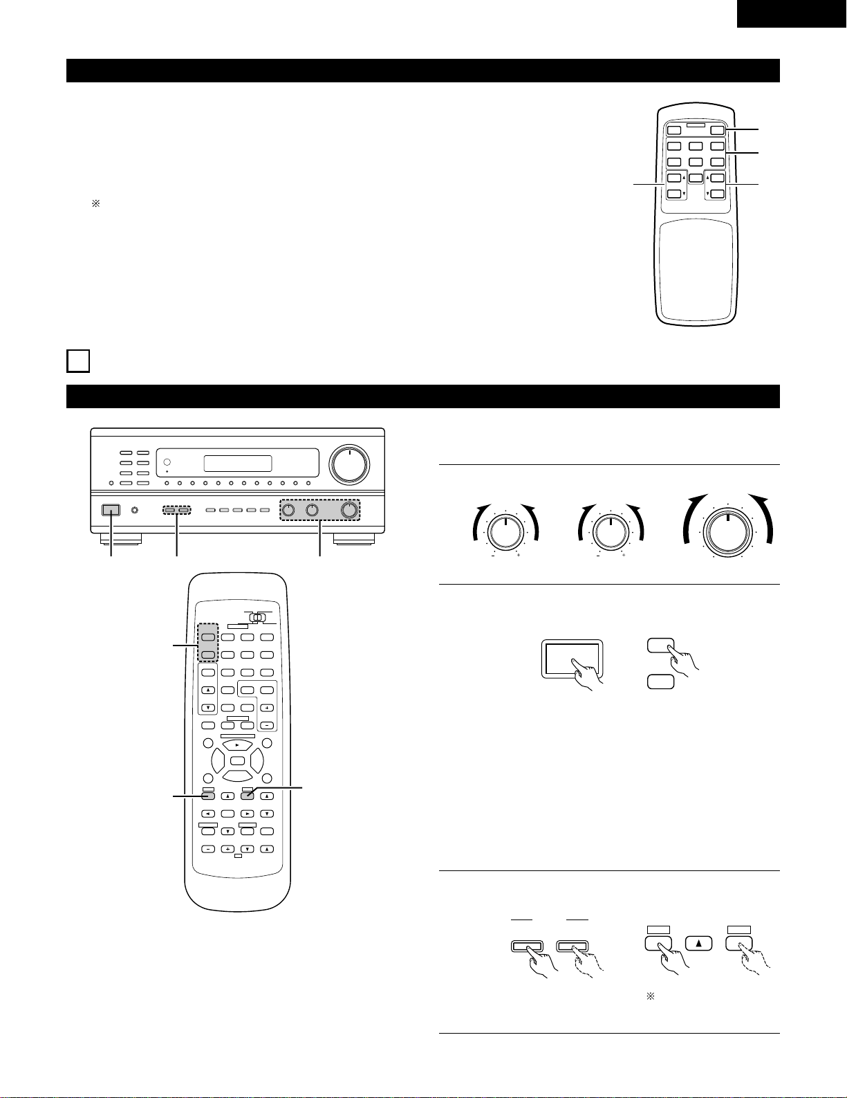
Remote control unit (RC-872)
• For details on the functions of these parts, refer to the pages given in parentheses ( ).
98
B
CD DVD/VDP
VCR
V.AUX
TUNER
SHIFT
REMOTE CONTROL UNIT RC-872
VOLUME
CHANNEL
DISPLAY
MUTING
TITLE
DISC SKIP+
MULTI
MULTI
VOL.
TAPE
MONITOR
CD·MD/CDR·DVD/VDP
TV
SET UP
SELECT
MENU
CHANNEL
ON
OFF
RECEIVER
DVD/VDP
TV VCR
PHONO
0
0
2
2
3
AUDIO
CD
MD/CD-R
VIDEO
POWER
DECK
·
VCR
6
7
6
7
VIDEO SELECT
SP-A SP-B
STATUS
RETURN
VOLUME
System buttons (DECK, VCR) ……(13, 16)
VIDEO SELECT button ………………(22)
Remote control signal
transmitter………………………………(12)
POWER buttons …………………(16, 17)
VOLUME control
buttons …………………………………(18)
MUTING button ………………………(22)
System buttons (TV) …………………(16)
STATUS button…………………………(23)
System buttons
(CD, MD/CD-R, DVD/VDP) ………(13, 16)
Mode selector switch ……………(13, 14)
Input source selector
buttons …………………………………(18)
SPEAKER B button ……………………(17)
Preset memory selector
buttons …………………………………(26)
SPEAKER A button ……………………(17)
MULTI SOURCE button …………(19, 20)
NOTE:
• The shaded buttons do not function with the this unit.
(Nothing happens when they are pressed.)
12
ENGLISH
7
REMOTE CONTROL UNIT
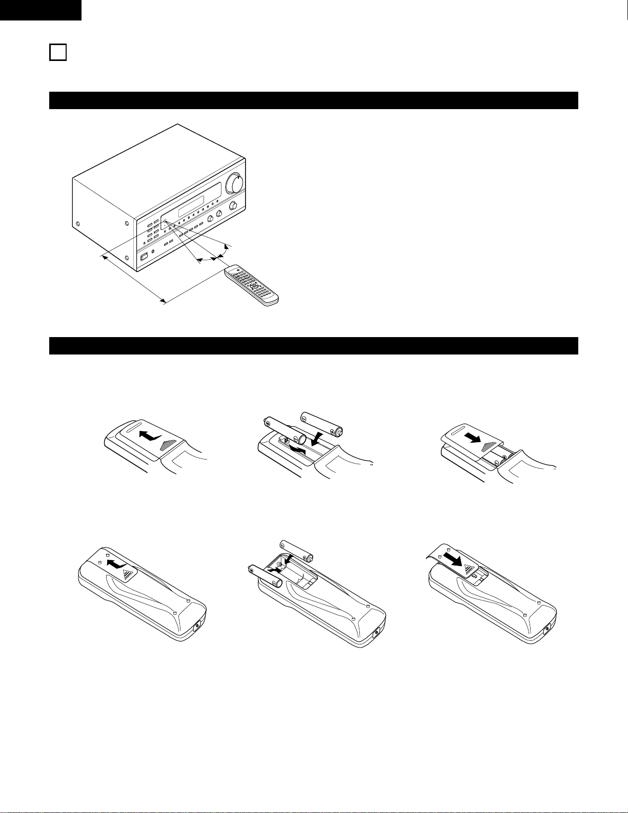
Following the procedure outlined below, insert the batteries before using the remote control unit.
Range of operation of the remote control unit
Inserting the batteries
Point the remote control unit at the remote control sensor as shown
on the diagram at the left.
NOTES:
• The remote control unit can be used from a straight distance of
approximately 7 meters/23 feet, but this distance will shorten or
operation will become difficult if there are obstacles between the
remote control unit and the remote control sensor, if the remote
control sensor is exposed to direct sunlight or other strong light, or
if operated from an angle.
• Neon signs or other devices emitting pulse-type noise nearby may
result in malfunction, so keep the set as far away from such
devices as possible.
B
9
8
B
0
0
2
2
3
6
7
6
7
Approx. 7 m/23 feet
q Press as shown by the arrow and slide
off.
w Insert the R6P/AA batteries properly, as
shown on the diagram.
e Close the lid.
NOTES:
• Be sure the polarities are correct. (See the illustration inside the battery compartment.)
• Remove the batteries if the remote control transmitter will not be used for an extended period of time.
• If batteries leak, dispose of them immediately. Avoid touching the leaked material or letting it come in contact with clothing, etc. Clean the
battery compartment thoroughly before installing new batteries.
• Even if less than a year has passed, replace the batteries with new ones if the set does not operate even when the remote control unit is
operated nearby the set. (The included battery is only for verifying operation. Replace it with a new battery as soon as possible.)
• When replacing the batteries, after removing them wait for about one minute before inserting the new batteries.
30°
30°
For remote control unit (RC-872)
For multi-source remote control unit (RC-873)
q Press as shown by the arrow and slide
off.
w Insert the R03/AAA batteries properly, as
shown on the diagram.
e Close the lid.
MD
13
ENGLISH
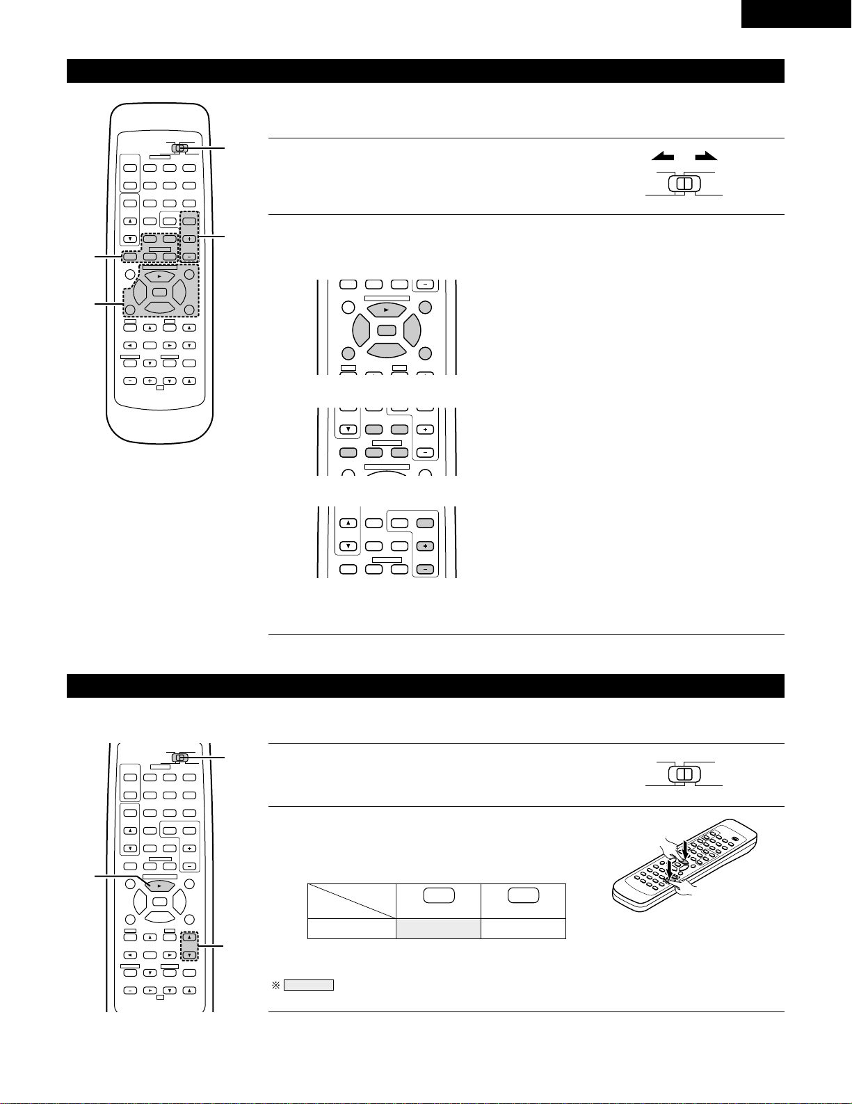
Operating DENON audio components
DENON remote-controllable audio components can be controlled using this unit’s remote control unit.
Note that some components, however, cannot be operated with this remote control unit.
2
Use the buttons shown below to operate the audio component.
For details, refer to the respective component’s manual.
1
Set the slide switch to the position for the component to
be operated (CD or MD/CD-R).
AUDIO
CD
MD/CD-R
VIDEO
98
TITLE
DISC SKIP+
CD·MD/CDR·DVD/VDP
0
0
2
2
3
6
7
SP-A SP-B
DISC SKIP+
MULTI
VOL.
CD·MD/CDR·DVD/VDP
CHANNEL
0
0
2
DECK
·
VCR
6
7
a. For CD player and MD/CD-R
b. For tape deck (DECK)
6,7 : Manual search (reverse and forward)
2 : Stop
1 : Play
8,9 : Auto search
3 : Pause
DISC : Disc selection
SKIP+ (CD changer only)
6 : Reverse
7 : Forward
2 : Stop
1 : Forward play
0 : Reverse play
98
B
CD DVD/VDP
VCR
V.AUX
TUNER
SHIFT
REMOTE CONTROL UNIT RC-872
VOLUME
CHANNEL
DISPLAY
MUTING
VOLUME
TITLE
DISC SKIP+
MULTI
MULTI
VOL.
TAPE
MONITOR
CD·MD/CDR·DVD/VDP
TV
SET UP
SELECT
MENU
CHANNEL
ON
OFF
RECEIVER
DVD/VDP
TV VCR
PHONO
0
0
2
2
3
AUDIO
CD
MD/CD-R
VIDEO
POWER
DECK
·
VCR
6
7
6
7
VIDEO SELECT
SP-A SP-B
STATUS
RETURN
2-b
2-a
2-c
1
TUNER SHIFT
MULTI
VOL.
TAPE
MONITOR
CHANNEL
0
0
2
DECK
·
VCR
6
7
c. For TUNER
SHIFT : Switch preset channel range
CHANNEL : Preset channel
+, – up/down
NOTE:
• Tape deck (DECK) and TUNER can be operated when the switch is at “AUDIO” position.
Preset memory (Audio component)
DENON components can be operated by setting the preset memory for MD or CD-R.
98
B
CD DVD/VDP
VCR
V.AUX
TUNER
SHIFT
REMOTE CONTROL UNIT RC 872
VOLUME
CHANNEL
DISPLAY
MUTING
VOLUME
TITLE
DISC SKIP+
MULTI
MULTI
VOL.
TAPE
MONITOR
CD·MD/CDR·DVD/VDP
TV
SET UP
SELECT
MENU
CHANNEL
ON
OFF
RECEIVER
DVD/VDP
TV VCR
PHONO
0
0
2
2
3
AUDIO
CD
MD/CD-R
VIDEO
POWER
DECK
·
VCR
6
7
6
7
VIDEO SELECT
SP-A SP-B
STATUS
RETURN
2
1
2
1
Set the slide switch to "MD/CD-R".
AUDIO
CD
MD/CD-R
VIDEO
2
Holding in the PLAY (1) button, press the button for the
components you want to set. (Refer to table 1.)
B
NOTE:
•
The memory can only be preset for either the MD or the CD-R.
Preset codes set upon shipment from the factory and when reset.
VOLUME
CD-R
PLAY (1)
•
ª
Table 1: Combinations of Personal System
Codes
VOLUME
14
ENGLISH
DENON A
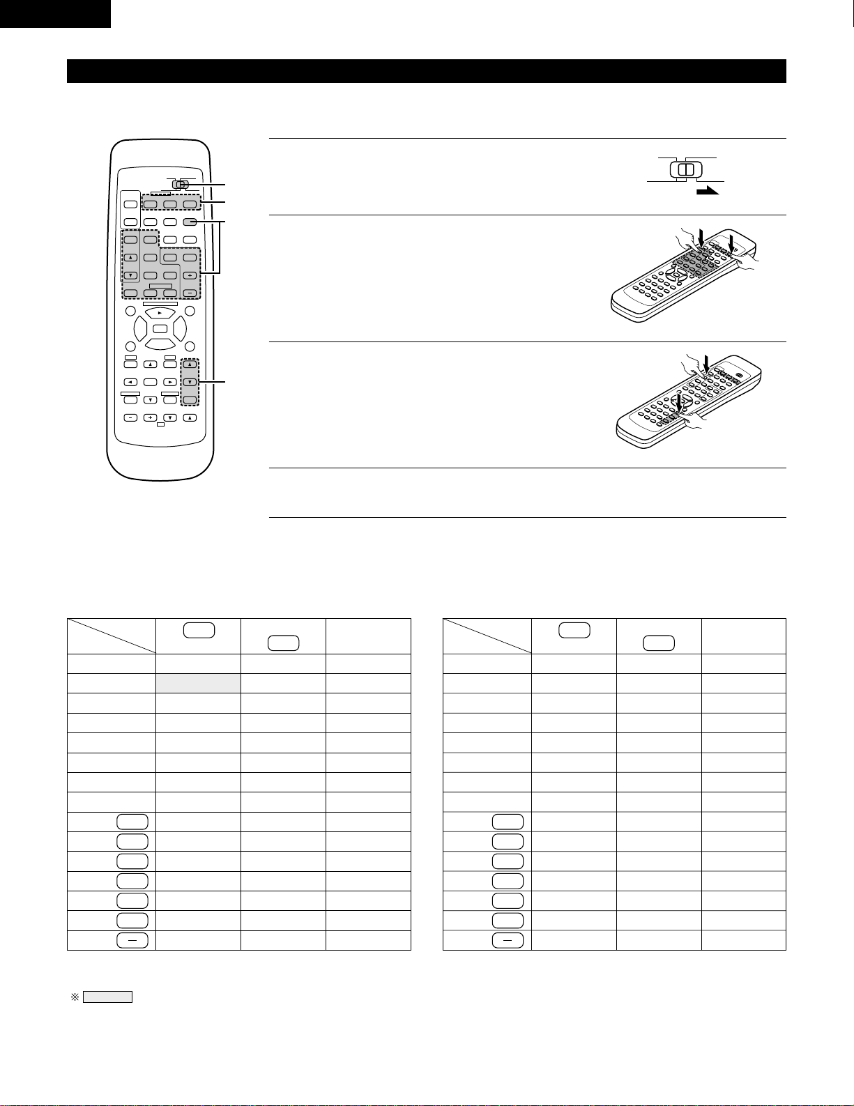
Preset memory (Video component)
DENON and other makes of components can be operated by setting the preset memory for your make of video component. Operation is not
possible for some models.
1
Set the slide switch to “VIDEO”.
3
Next, while holding in the POWER button, press the
button for the code in block B.
(Refer to Table 2.)
4
To continue registering other components, repeat steps 2 to 3.
B
AUDIO
CD
MD/CD-R
VIDEO
2
Holding in the POWER button of the components
(DVD/VDP, VCR or TV) you want to set, press the button
for the corresponding manufacturer in block A.
(Refer to Table 2.)
B
This remote control unit can be used to operate components of other manufacturers without using the learning function by registering the
manufacturer of the component as shown on Table 2.
Table 2: Combinations of Personal System Codes for Different Manufacturers
“DVD”
A
B
—
—
—
—
—
—
—
—
—
—
—
—
—
—
—
98
B
CD DVD/VDP
VCR
V.AUX
TUNER
SHIFT
REMOTE CONTROL UNIT RC-872
VOLUME
CHANNEL
DISPLAY
MUTING
VOLUME
TITLE
DISC SKIP+
MULTI
MULTI
VOL.
TAPE
MONITOR
CD·MD/CDR·DVD/VDP
TV
SET UP
SELECT
MENU
CHANNEL
ON
OFF
RECEIVER
DVD/VDP
TV VCR
PHONO
0
0
2
2
3
AUDIO
CD
MD/CD-R
VIDEO
POWER
DECK
·
VCR
6
7
6
7
VIDEO SELECT
SP-A SP-B
STATUS
RETURN
B
1
2,3
A
0
1
6
7
2
MASTER VOL.
MUTING
ª
—
DENON B
—
—
—
—
—
—
—
—
—
—
—
—
—
—
—
—
PANASONIC
—
—
—
SONY
PIONEER
TOSHIBA
—
—
—
—
DVD/VDP
MULTI
VCR
MULTI VOL. •
TAPE MONITOR
TUNER
SHIFT
MULTI VOL. ª
TAPE
TAPE
TUNER
TAPE
TAPE
TAPE
—
“VDP”
A
B
DENON C
—
—
—
—
—
—
—
—
—
—
—
—
—
—
DENON B
—
—
—
—
—
—
—
—
—
—
—
—
—
—
DENON A
MITUBISHI
PANASONIC
—
SONY
PIONEER
—
—
—
—
PHILIPS
RCA
—
MAGNAVOX
+
TUNER
MASTER VOL.
•
MASTER VOL.
MUTING
ª
MASTER VOL.
•
0
1
6
7
2
DVD/VDP
MULTI
VCR
MULTI VOL. •
TAPE MONITOR
TUNER
SHIFT
MULTI VOL. ª
TAPE
TAPE
TUNER
TAPE
TAPE
TAPE
+
TUNER
NOTE:
•
The memory can only be preset for either the DVD or the VDP.
Preset codes set upon shipment from the factory and when reset.
15
ENGLISH
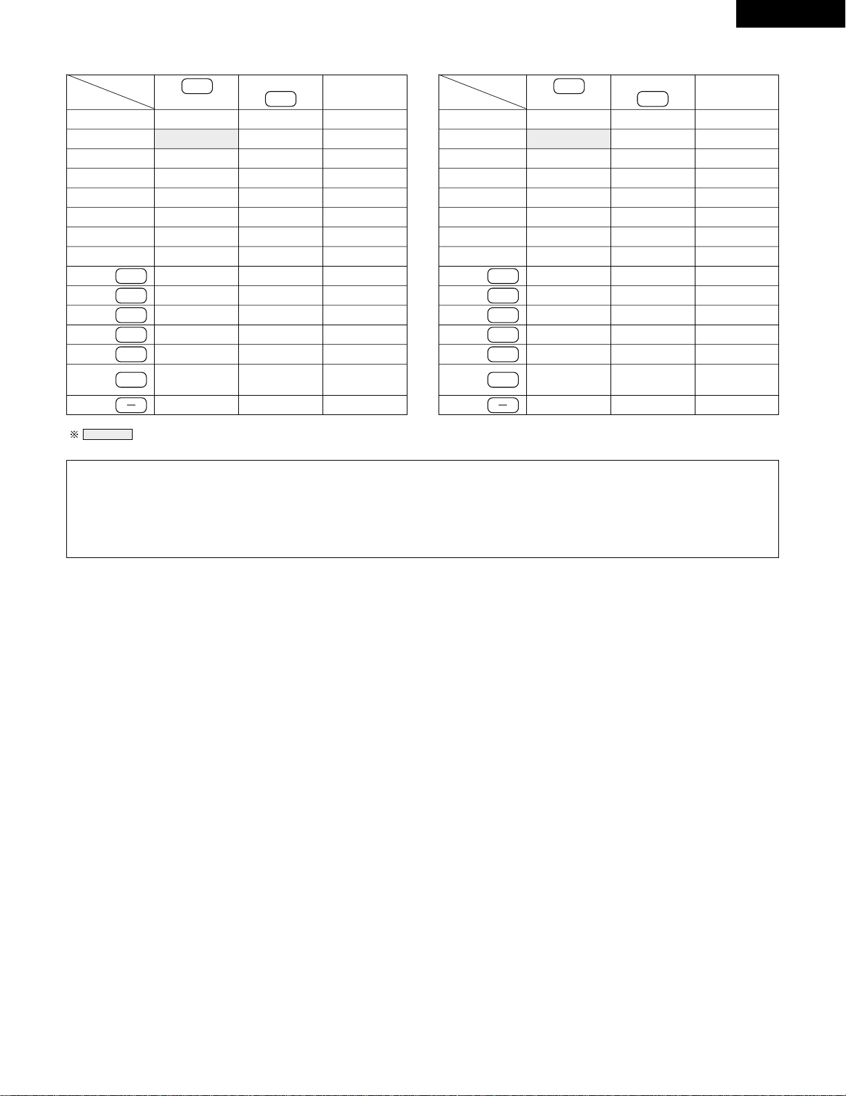
NOTES:
• The signals for the pressed buttons are emitted while setting the preset memory. To avoid accidental operation, cover the remote
control unit’s transmitting window while setting the preset memory.
• Some models and years of manufacture of components of the manufacturers listed on Table 2 cannot be used.
• The unit is equipped with several types of remote control codes which depend on the manufacturer. If there is no operation when set to
A, please change the setting to B or C and try again.
HITACHI A
“VCR”
A
B
—
—
MITUBISHI C
PANASONIC C
JVC (VICTOR) C
SONY C
—
—
—
—
NEC C
PHILIPS C
—
—
MAGNAVOX C
—
HITACHI B
MITUBISHI B
PANASONIC B
JVC (VICTOR) B
SONY B
—
TOSHIBA B
SANYO B
SHARP B
NEC B
PHILIPS B
RCA B
GENERAL
ELECTRIC B
MAGNAVOX B
—
MITUBISHI A
PANASONIC A
JVC (VICTOR) A
SONY A
PIONEER
TOSHIBA A
SANYO A
SHARP A
NEC A
PHILIPS A
RCA A
GENERAL
ELECTRIC A
MAGNAVOX A
HITACHI
“TV”
A
B
—
—
—
—
—
—
—
—
—
—
—
—
—
—
—
—
—
MITUBISHI B
PANASONIC B
—
—
—
—
—
—
—
—
—
GENERAL
ELECTRIC B
—
—
MITUBISHI A
PANASONIC A
JVC (VICTOR)
SONY
PIONEER
TOSHIBA
SANYO
SHARP
NEC
PHILIPS
RCA
GENERAL
ELECTRIC A
MAGNAVOX
Preset codes set upon shipment from the factory and when reset.
MASTER VOL.
MUTING
ª
MASTER VOL.
•
0
1
6
7
2
DVD/VDP
MULTI
VCR
MULTI VOL. •
TAPE MONITOR
TUNER
SHIFT
MULTI VOL. ª
TAPE
TAPE
TUNER
TAPE
TAPE
TAPE
+
TUNER
MASTER VOL.
MUTING
ª
MASTER VOL.
•
0
1
6
7
2
DVD/VDP
MULTI
VCR
MULTI VOL. •
TAPE MONITOR
TUNER
SHIFT
MULTI VOL. ª
TAPE
TAPE
TUNER
TAPE
TAPE
TAPE
+
TUNER
16
ENGLISH
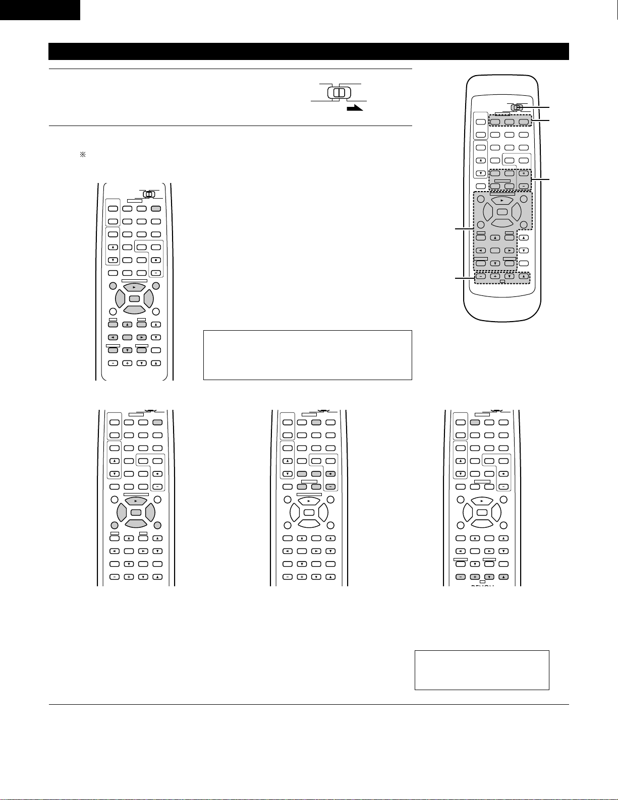
2
Operate the video component.
• For details, refer to the component’s operating instructions.
Some models cannot be operated with this remote control unit.
98
DISPLAY
MUTING
VOLUME
TITLE
DISC SKIP+
CD·MD/CDR·DVD/VDP
SET UP
SELECT
MENU
ON
OFF
RECEIVER
DVD/VDP
TV VCR
0
0
2
2
3
AUDIO
CD
MD/CDR
VIDEO
POWER
6
7
6
7
VIDEO SELECT
SP-A SP-B
STATUS
RETURN
a. For DVD player
POWER : Power on/off
2 : Stop
1 : Play
8,9 : Auto search (cue)
3 : Pause
TITLE : Call out title
MENU : Call out menu
DISPLAY : Switch display
SET UP : DVD setup
RETURN : Menu return
• , ª : Cursor up/down
0 , 1 : Cursor left/right
SELECT : Enter setting
DISC SKIP
+
: Disc selection
NOTE:
Some manufacturers use different names for the DVD
remote control buttons, so also refer to the instructions
on remote control for that component.
b. For video disc player (VDP) c. For video deck (VCR) d. For TV
98
VOLUME
TITLE
DISC SKIP+
CD·MD/CDR·DVD/VDP
SET UP
MENU
ON
OFF
RECEIVER
DVD/VDP
TV VCR
0
0
2
2
3
AUDIO
VIDEO
POWER
6
7
6
7
SP-A SP-B
98
CD DVD/VDP
VCR
V.AUX
TUNER
SHIFT
DISC SKIP+
MULTI
MULTI
VOL.
TAPE
MONITOR
CD·MD/CDR·DVD/VDP
CHANNEL
ON
OFF
RECEIVER
DVD/VDP
TV VCR
PHONO
0
0
2
2
3
AUDIO
VIDEO
POWER
DECK
·
VCR
6
7
6
7
98
B
CD DVD/VDP
VOLUME
CHANNEL
DISPLAY
MUTING
TV
SELECT
CHANNEL
ON
OFF
RECEIVER
DVD/VDP
TV VCR
PHONO
0
0
2
2
3
AUDIO
VIDEO
POWER
DECK
·
VCR
6
7
6
7
VIDEO SELECT
STATUS
RETURN
POWER : Power on/off
6,7 : Manual search
(reverse and forward)
2 : Stop
1 : Play
8,9 : Auto search (cue)
3 : Pause
POWER : Power on/off
6,7 : Manual search
(reverse and forward)
2 : Stop
1 : Play
CHANNEL : Switch channel
+,–
POWER : Power on/off
VOLUME : Volume
• , ª up/down
CHANNEL : Switch channel
+,–
Operating a video component stored in the preset memory
1
Set the slide switch to “VIDEO”.
98
B
CD DVD/VDP
VCR
V.AUX
TUNER
SHIFT
REMOTE CONTROL UNIT RC-872
VOLUME
CHANNEL
DISPLAY
MUTING
VOLUME
TITLE
DISC SKIP+
MULTI
MULTI
VOL.
TAPE
MONITOR
CD·MD/CDR·DVD/VDP
TV
SET UP
SELECT
MENU
CHANNEL
ON
OFF
RECEIVER
DVD/VDP
TV VCR
PHONO
0
0
2
2
3
AUDIO
CD
MD/CD-R
VIDEO
POWER
DECK
·
VCR
6
7
6
7
VIDEO SELECT
SP-A SP-B
STATUS
RETURN
2-c
1
2
2-a,b
2-d
AUDIO
CD
MD/CD-R
VIDEO
NOTE:
The TV can be operated when the
switch is at any position.
17
ENGLISH
Multi-source remote control unit (RC-873)
This is a remote control unit for multi-source and multi-zone playback.
Buttons w can not be used when the main unit’s multi-source mode is set to the REC OUT mode.
Buttons r can only be used when the main unit’s multi-source mode is set to the MULTI mode.
q The main unit's POWER (ON, OFF) buttons.
w MULTI SOURCE terminal output function control buttons (PHONO, TUNER, CD, DVD/VDP, VCR, V.AUX
and TAPE).
e MULTI SOURCE terminal output level control buttons (VOLUME up and down).
DEFAULT SETTING (MULTI VOLUME LEVEL) : - - - dB (MINIMUM)
r PRESET up and down buttons (when MULTI SOURCE function is set to TUNER).
B
MULTI SOURCE REMOTE CONTROL UNIT
RC-873
POWER
PHONO CD
DVD/VDP
OFF
ON
VCR V.AUX
TUNER
PRESET VOLUME
TAPE
MONITOR
8
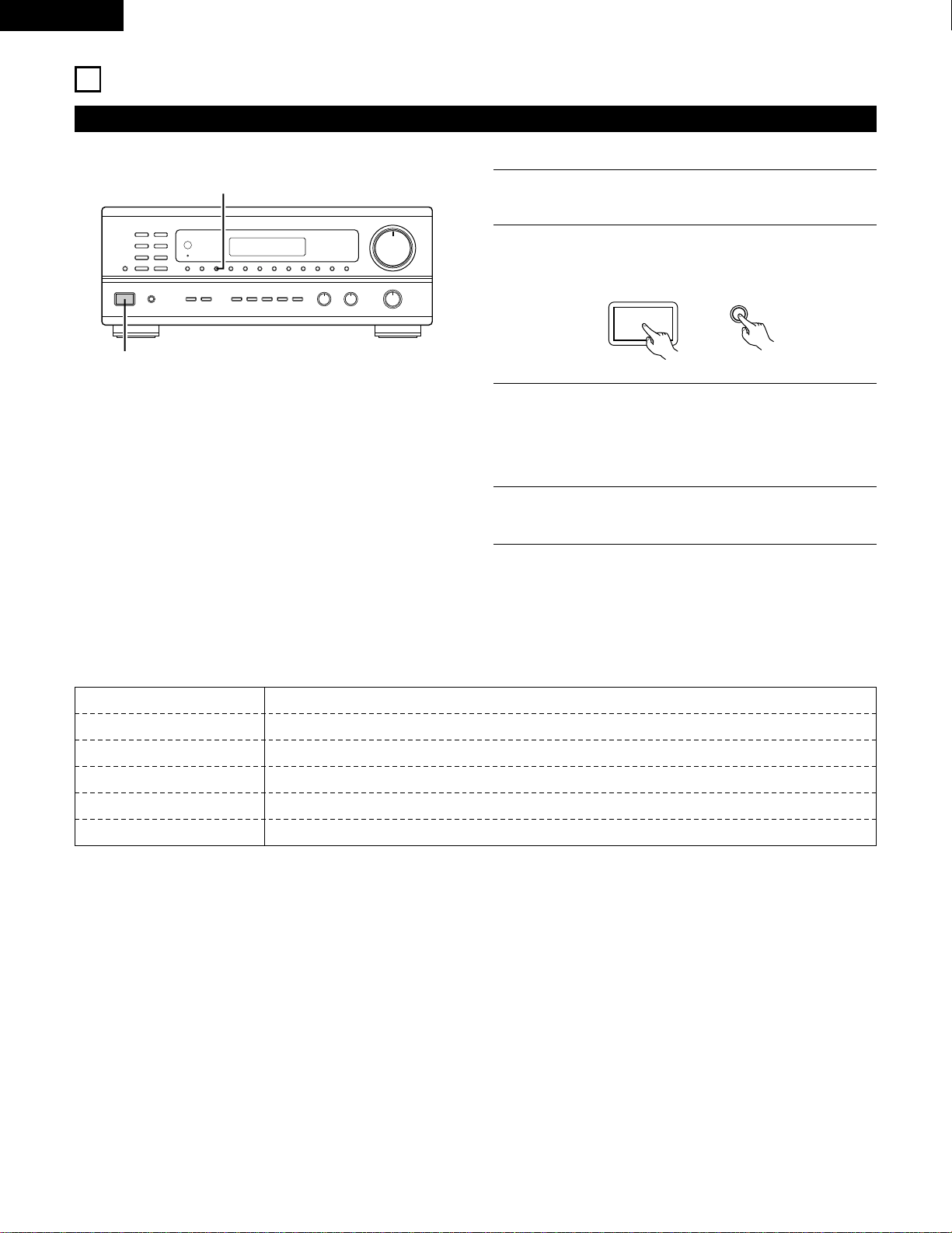
OPERATIONS
Before operating
Preparations:
Check that all connections are proper.
1
Set to the center position.
BASS TREBLE BALANCE
LR
2
Turn on the power.
Press the power operation switch (button).
ON / STANDBY
• ON/STANDBY
When the button is pressed, the power turns on and the
display lights.
When pressed again, the power turns off, the standby mode
is set and the display turns off.
Several seconds are required from the time the power
switch is set to the “ON” position until sound is output. This
is due to the built-in muting circuit that prevents noise when
the power switch is turned on and off.
Set the power operation switch to this position, the power
on and off from the included remote control unit.
1
B
23
98
B
CD DVD/VDP
VCR
V.AUX
TUNER
SHIFT
REMOTE CONTROL UNIT RC-872
VOLUME
CHANNEL
DISPLAY
MUTING
VOLUME
TITLE
DISC SKIP+
MULTI
MULTI
VOL.
TAPE
MONITOR
CD·MD/CDR·DVD/VDP
TV
SET UP
SELECT
MENU
CHANNEL
ON
OFF
RECEIVER
DVD/VDP
TV VCR
PHONO
0
0
2
2
3
AUDIO
CD
MD/CD-R
VIDEO
POWER
DECK
·
VCR
6
7
6
7
VIDEO SELECT
SP-A SP-B
STATUS
RETURN
3
3
2
3
Select the front speakers.
Press the SPEAKER A or B button turn the speaker on.
A
B
SPEAKER
ON
OFF
RECEIVER
SET UP
MENU
SP-A SP-B
q
w
er
Set the slide switch to
“AUDIO”.

18
ENGLISH
Playing the program source
B
13
1
Press the button for the program source to be played.
EX 1: CD
EX 2: TAPE
• Press the button once to switch the source to TAPE MONITOR
input, again to cancel input.
2
Start playback on the selected component.
For operating instructions, refer to the various components’
manuals.
3
Adjust the VOLUME control.
CD
CD
TAPE
MONITOR
TAPE
MONITOR
VOLUME
VOLUME
Adjusting the BALANCE, TONE, and LOUDNESS control
1
B
243
1
Adjust the left/right BALANCE control.
Turn the control counterclockwise to
reduce the volume of the right
channel, clockwise to reduce the
volume of the left channel.
BALANCE
LR
2
Adjust the BASS and TREBLE control.
BASS
TREBLE
Turn the control clockwise to increase
the bass, counterclockwise to decrease
it.
Turn the control clockwise to increase
the treble, counterclockwise to decrease
it.
3
Press the TONE DEFEAT button.
Use this when you do not want to adjust
the sound.
TONE
DEFEAT
4
Press the LOUDNESS button.
Press the loudness button ON when
listening to music at a low volume.
The low notes and high notes will be
corrected to produce a natural sound.
LOUDNESS button can be used when
the TONE DEFEAT ON mode.
LOUDNESS
98
CD DVD/VDP
VCR
V.AUX
TUNER
SHIFT
MUTING
VOLUME
TITLE
DISC SKIP+
MULTI
MULTI
VOL.
TAPE
MONITOR
CD·MD/CDR·DVD/VDP
SET UP
SELECT
MENU
CHANNEL
ON
OFF
RECEIVER
DVD/VDP
TV VCR
PHONO
0
0
2
2
3
DECK
·
VCR
6
7
6
7
VIDEO SELECT
SP-A SP-B
STATUS
3
1
19
ENGLISH
Multi-Source recording/playback
The Multi-Source function allows you to record a source other than the source currently playing or to output its signal to the MULTI SOURCE
output terminal.
2
Recording a source other than the one currently playing (REC OUT mode)
B
1 2
1
Press the MULTI SOURCE MODE
button until “REC OUT” appears on
the display.
MULTI SOURCE
MODE
SELECT
2
Select the source to be output to
the recording output terminal. Press
the MULTI SOURCE SELECT button
repeatedly until the desired source
appears on the display.
3
The selected source is indicated.
The signals of the source selected with the REC OUT mode
are also output from the MULTI SOURCE AUDIO/VIDEO
OUT terminals.
To cancell the REC OUT mode.
Press the MULTI SOURCE MODE button repeatedly until
“SOURCE” appears on the display.
MULTI SOURCE
MODE
SELECT
The REC OUT mode cannot be set from the remote control
unit.
AUTO RDS CH
STEREO TUNED
DISPLAY
MULTI TONE SP-A SP-B PHONO CD TUNER VDP VCR V.AUX TAPE
3
20
ENGLISH
2
Playing a source other than the one currently playing in a different room (MULTI mode)
B
1 3
98
B
CD DVD/VDP
VCR
V.AUX
TUNER
SHIFT
REMOTE CONTROL UNIT RC-872
VOLUME
CHANNEL
DISPLAY
MUTING
MASTER
VOL.
TITLE
DISC SKIP+
MULTI
MULTI
VOL.
TAPE
MONITOR
CD·MD/CDR·DVD/VDP
TV
SET UP
SELECT
MENU
CHANNEL
ON
OFF
RECEIVER
DVD/VDP
TV VCR
PHONO
0
0
2
2
3
AUDIO
CD
MD/CD-R
VIDEO
POWER
DECK
·
VCR
6
7
6
7
VIDEO SELECT
SP-A SP-B
STATUS
RETURN
5
3
AUTO RDS CH
STEREO TUNED
DISPLAY
MULTI TONE SP-A SP-B PHONO CD TUNER VDP VCR V.AUX TAPE
42
RC-872
RC-873
B
MULTI SOURCE REMOTE CONTROL UNIT
RC-873
POWER
PHONO CD
DVD/VDP
OFF
ON
VCR V.AUX
TUNER
PRESET VOLUME
TAPE
MONITOR
3
56
1
Press the MULTI SOURCE MODE
button repeatedly until “MULTI
OUT” appears on the display.
MULTI SOURCE
MODE
SELECT
3
Select the source to be output to the MULTI SOURCE output
terminal. Press the MULTI SOURCE SELECT button repeatedly
until the desired source appears on the display.
4
The selected source is indicated.
To cancell the MULTI mode.
Press the MULTI SOURCE MODE button or the MULTI
button on the RC-872 remote control unit repeatedly until
“SOURCE” appears on the display.
2
Turn on the “MULTI” indicator.
NOTE:
The signals of the source selected in the MULTI mode are also
output from the TAPE and VCR recording output terminals.
5
The output level of the MULTI SOURCE AUDIO terminals can
be controlled using the MULTI VOLUME • and ª buttons on
the RC-872 remote control unit or the VOLUME up and down
buttons on the RC-873 multi source remote control unit.
MULTI
VOL.
VOLUME
6
When the MULTI SOURCE function is set to TUNER, the
preset channel can be selected using the PRESET • and ª
buttons on the RC-873 multi source remote control unit. (This is
only possible when the main unit is in the MULTI mode.)
NOTE:
Note that this also switches the preset reception channel on
the main unit when playing or recording the tuner in the
MULTI mode.
When the MULTI SOURCE button on the RC-872 remote
control unit is pressed, the MULTI mode is set directly (the
“MULTI” indicator lights), and the source to be output from
the MULTI SOURCE terminals can be selected.
When the PHONO
~ TAPE buttons on the RC-873 multi
source remote control unit is pressed, the MULTI mode is
set directly (the “MULTI” indicator lights), and the source to
be output from the MULTI SOURCE terminals can be
selected directly. (This cannot be selected when the main
unit is in the REC OUT mode.)
MULTI SOURCE
MODE
SELECT
MULTI
(RC-872) (RC-873)
DEFAULT SETTING (MULTI VOLUME LEVEL) :
- - - dB (MINIMUM)
(RC-872)
21
ENGLISH
2
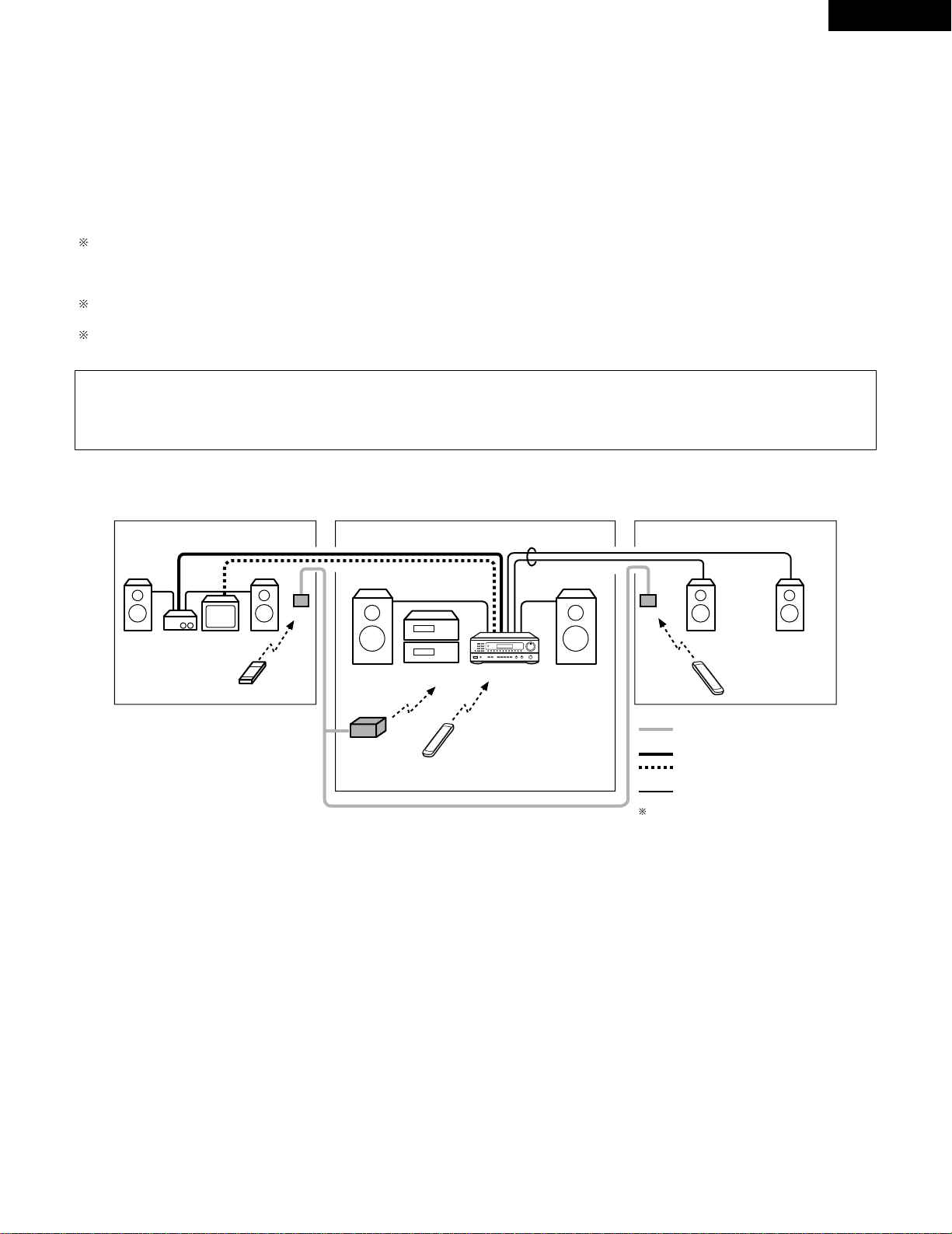
Multi-source and multi-zone playback
MULTI ROOM MUSIC ENTERTAINMENT SYSTEM
• When the outputs of the MULTI SOURCE AUDIO/VIDEO OUT terminals are wired and connected to power amplifiers or TV displays installed
in other rooms, different sources can be played in rooms other than the main room in which the this unit and the playback devices are
installed. (Refer to SUB ROOM-1 on the diagram.)
• When the output of the SPEAKER SYSTEM-B terminals is wired and connected to speakers in a sub room, the same source can be played in
both the main room and sub room. Set the this unit’s SPEAKER A/B selector according to the room in which the source is to be played. (Refer
to SUB ROOM-2 on the diagram.)
• When a separately sold room-to-room remote control unit (DENON RC-616 or 617) is wired and connected between the main room and the
sub room, the remote-controllable devices in the main room can be controlled from the sub room using the remote control unit.
With SUB-ROOM-1 multi-source playback, the this unit’s MULTI SOURCE output can be controlled with the included RC-873 multi source
remote control unit.
Operations on the RC-873 remote control unit other than turning the multi source output volume up and down can not be performed when the
main unit is in the REC OUT mode.
With SUB ROOM-2 playback, the this unit and DENON CD players or tape decks etc. can be controlled using the included RC-872 system
remote control unit.
To control playback devices other than the ones above, either use that device’s remote control unit or preset a separately sold programmable
remote control unit (DENON RC-770, etc.).
NOTE:
• Use a 75 Ω /ohms coaxial pin-plug cord for video signals to connect and wire the MULTI SOURCE VIDEO output. For the AUDIO output,
use high quality pin-plug cords and wire in such a way that there is no humming or noise.
• For instructions on installation and operation of separately sold devices, refer to the devices’ operating instructions.
SUB ROOM-1 MAIN ROOM
SUB ROOM-2
AMPLIFIRE
TV
RC-617
DRA-685
RC-616
RC-617
SPEAKER SYSTEM -B
B
ROOM-TO-ROOM REMOTE CONTROL
SYSTEM (separately sold) control line
MULTI SOURCE AUDIO signal cable
SPEAKER cable
Refer to CONNECTIONS on pages 6 and 7.
MULTI SOURCE VIDEO signal cable
(75
º / ohms)
9
8
B
0
0
2
2
3
6
7
6
7
B
MULTI ROOM MUSIC ENTERTAINMENT SYSTEM
MULTI SOURCE REMOTE
CONTROL UNIT RC-873 (or
PROGRAMABLE REMOTE
CONTROL UNIT RC-770)
SYSTEM REMOTE
CONTROL UNIT RC-872
RC-872 (or PROGRAMABLE
REMOTE CONTROL UNIT
RC-770)
• Accessories
•
SYSTEM REMOTE CONTROL UNIT
RC-872
•
MULTI SOURCE REMOTE CONTROL
UNIT RC-873
• Sold Separately
•
IR RETRANSMITTER RC-616
•
IR SENSOR RC-617
•
PROGRAMABLE REMOTE CONTROL
UNIT RC-770
22
ENGLISH
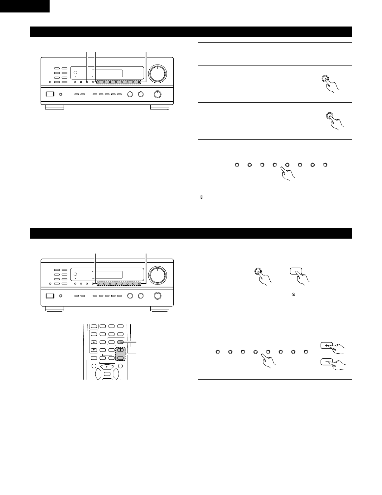
Simulcast playback
1
Holding the VIDEO SELECT button until the desired source
appears on the display.
The video source switches as follows each time the button is
pressed:
Cancelling simulcast playback.
• Press the VIDEO SELECT button again.
• Switch the program source to the component connected to
the video.
Use this switch to monitor a video source other than the audio source.
111
B
1
DVD/VDP VCR V.AUX
VIDEO
SELECT
VIDEO SELECT
RETURN
B
REMOTE CONTROL UNIT RC-872
VOLUME
CHANNEL
DISPLAY
MUTING
MASTER
VOL.
TV
SET UP
SELECT
MENU
VIDEO SELECT
STATUS
RETURN
1
Using the muting function
Use this to turn off the audio output temporarily.
• Caution:
Switching off the power of the unit will cancel the settings.
1
B
REMOTE CONTROL UNIT RC-872
VOLUME
CHANNEL
DISPLAY
MUTING
VOLUME
TV
SET UP
SELECT
MENU
VIDEO SELECT
SP-A SP-B
STATUS
RETURN
1
Press the MUTING button.
Cancelling MUTING mode.
Press the MUTING button again.
MUTING
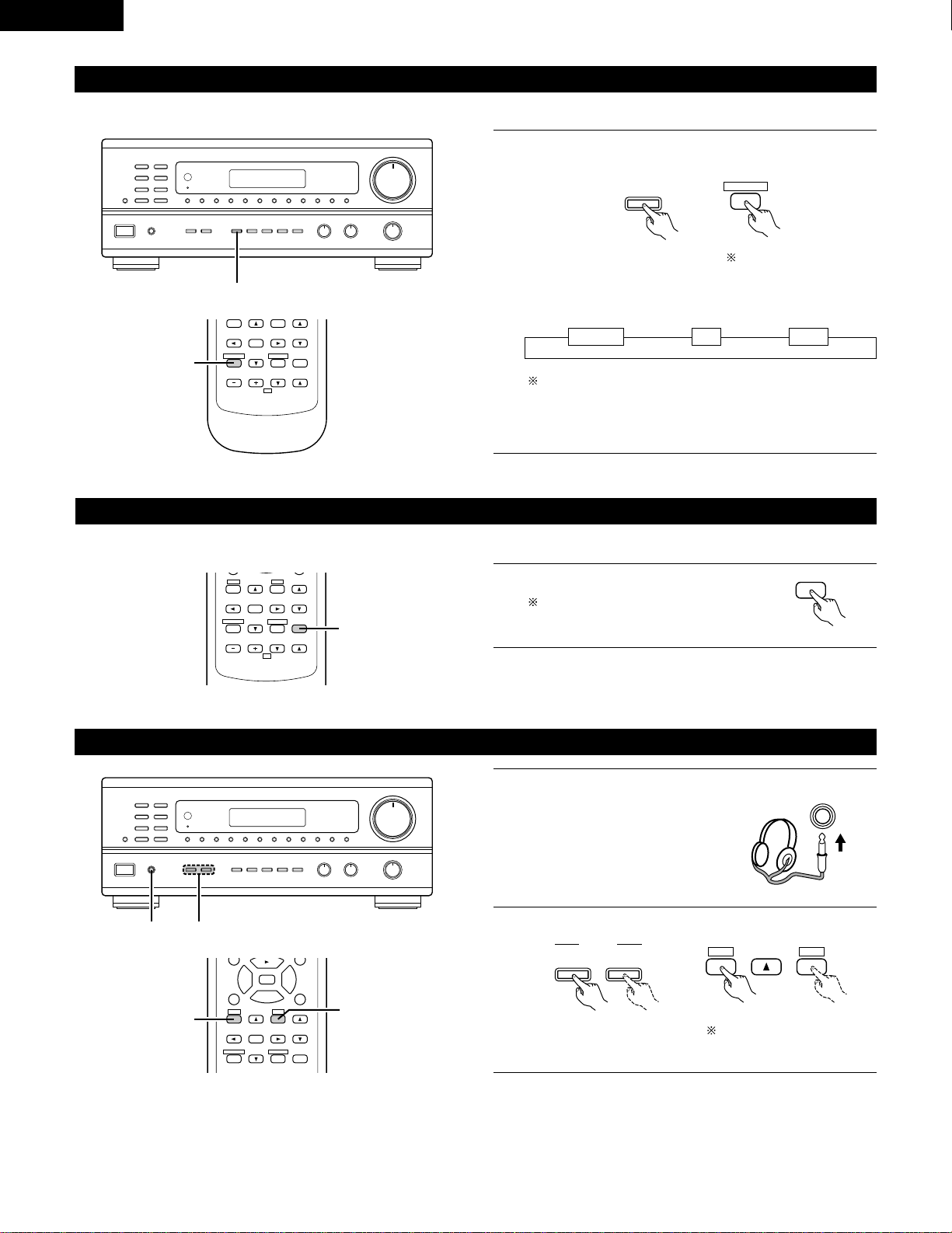
Listen with headphones
1
Connect the headphones to the
headphones jack of the front panel.
PHONES
2
Press the SPEAKER A or B button turn the speaker off.
B
12
A
B
SPEAKER
SET UP
MENU
SP-A SP-B
98
DISPLAY
MUTING
VOLUME
TITLE
SET UP
SELECT
MENU
2
3
6
7
VIDEO SELECT
SP-A SP-B
STATUS
RETURN
2
2
Set the slide switch to
“AUDIO”.
Set the slide switch to
“AUDIO”.
23
ENGLISH
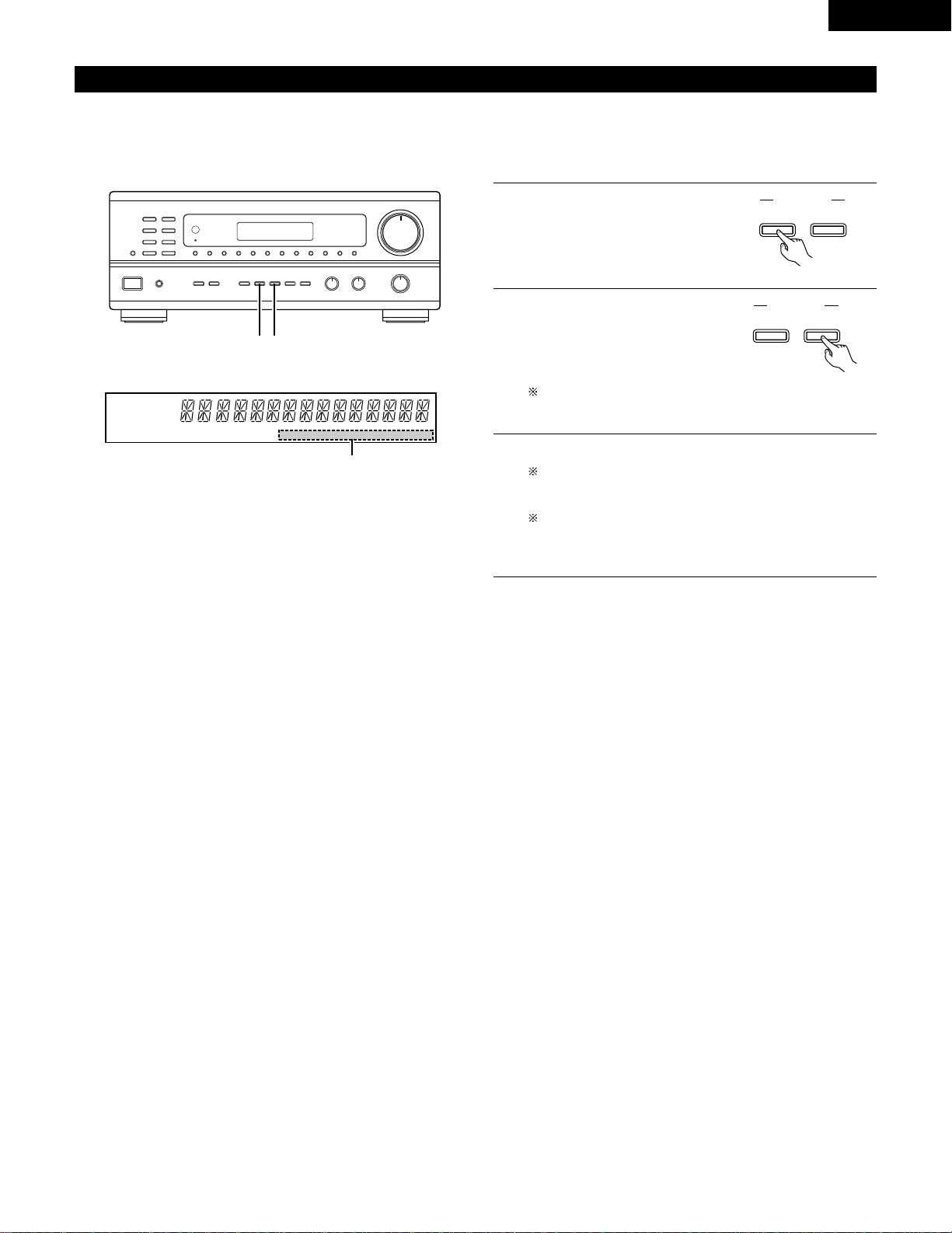
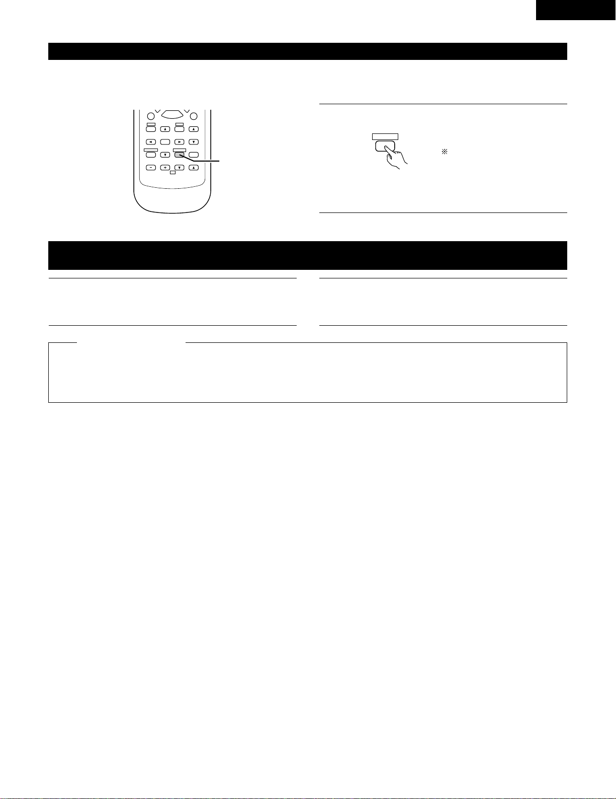
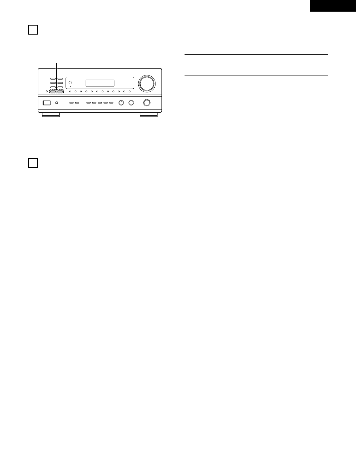
Front panel display
When an operation is performed on the remote control unit, that operation appears on the display, making it possible to check the operation
visually.
The set’s operating status can also be checked on the display using the procedure described below.
1
Press the STATUS button.
DISPLAY
STATUS
• The input and output sources and the setting, etc., appear in
order on the display each time the button is pressed.
B
REMOTE CONTROL UNIT RC-872
VOLUME
CHANNEL
DISPLAY
MUTING
VOLUME
TV
SET UP
SELECT
MENU
2
6
7
VIDEO SELECT
SP-A SP-B
STATUS
RETURN
1
1
Follow steps 1 to 3 under “Playing the program source”.
Recording the program source
(recording the source currently being monitored)
2
Start recording on the tape or video deck.
For instructions, refer to the component’s operating
instructions.
The signals of the source selected with the function selector button are output simultaneously to the TAPE and VCR REC OUT jacks. If a
total of two tape and/or video decks are connected and set to the recording mode, the same source can be recorded simultaneously on
every decks.
In addition, if the TAPE MONITOR button is pressed, the audio signals from the tape deck are output to the VCR AUDIO REC OUT jacks.
Simultaneous recording
2
Tape monitor function
When a three-head tape deck is used, the sound actually being recorded can be monitored during recording by pressing the TAPE MONITOR
button.
Press the button again to cancel monitoring.
Set the slide switch to “AUDIO”.
24
ENGLISH
LISTENING TO THE RADIO
Auto preset memory
NOTES:
• If an FM station cannot be preset automatically due to poor
reception, use the “Manual tuning” operation to tune in the
station, then preset it using the manual “Preset memory”
operation.
• To interrupt this function, press the power operation button.
2
3
This unit is equipped with a function for automatically searching for FM broadcast stations and storing them in the preset memory.
Switch on the unit using the main unit’s power operation
switch while holding in the MEMORY button. The unit
automatically begins searching for FM broadcast stations.
When the first FM broadcast station is found, that station is
stored in the preset memory at channel A1. Subsequent
stations are automatically stored in order at preset channels A2
to A8, B1 to B8, C1 to C8, D1 to D8 and E1 to E8, for a
maximum of 40 stations.
4
Channel A1 is tuned in after the auto preset memory operation
is completed.
9
B
2
2
AUTO TUNER PRESETS
A1 ~ A8 87.5/89.1/98.1/107.9/90.1/90.1/90.1/90.1 MHz
B1 ~ B8 520/600/1000/1400/1500/1710 kHz/90.1/90.1 MHz
C1 ~ C8 90.1 MHz
D1 ~ D8 90.1 MHz
E1 ~ E8 90.1 MHz
2
DEFAULT VALUE
ON / STANDBY
MEMORY
1
Switch off the unit.
25
ENGLISH
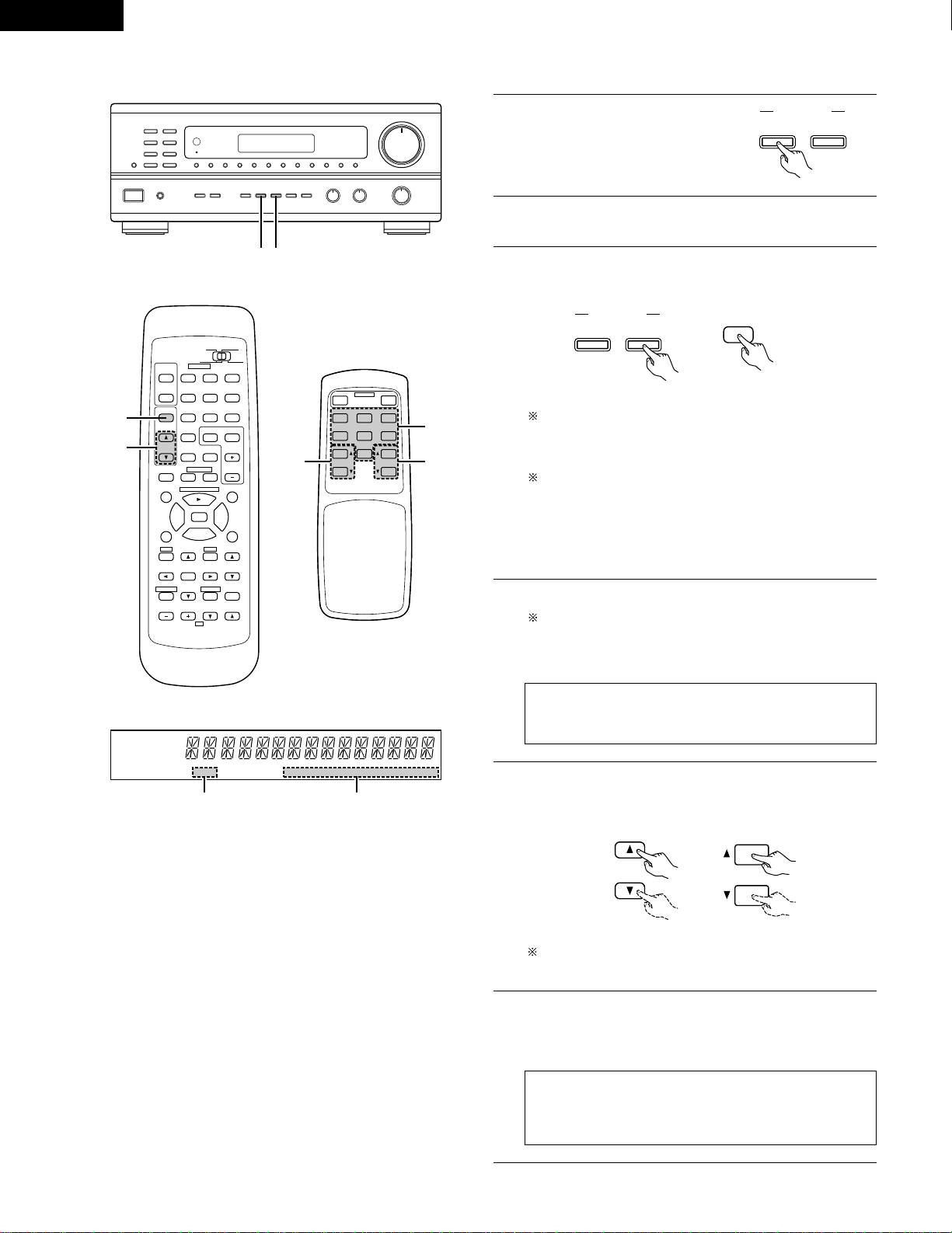
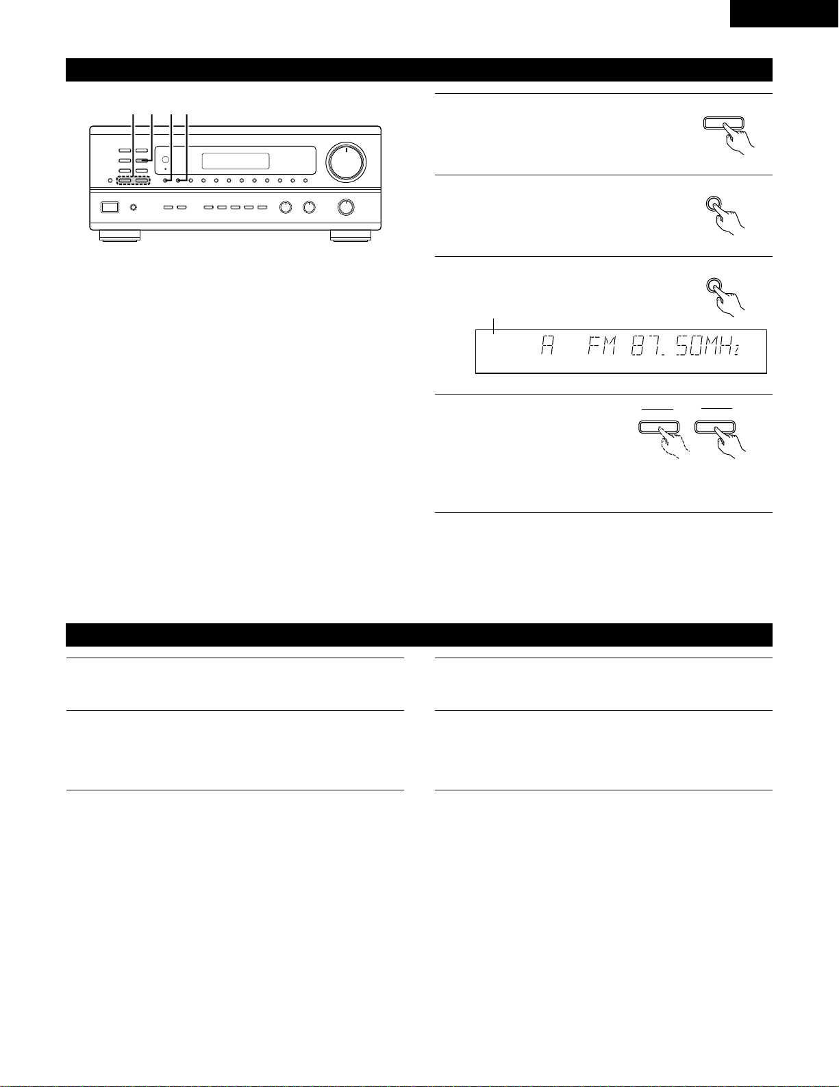
Auto tuning
1
Set the input function to “TUNER”.
2
Watching the display, press the BAND
button to select the desired band (AM or
FM).
BAND
3
Press the MODE button to set the auto
tuning mode.
AUTO CH
TUNED
TUNER
4
Press the TUNING UP or
DOWN button.
TUNING
UPDOWN
Lit
• Automatic searching begins, then stops when a station is
tuned in.
NOTE:
• When in the auto tuning mode on the FM band, the “STEREO”
indicator lights on the display when a stereo broadcast is tuned in.
At open frequencies, the noise is muted and the “TUNED” and
“STEREO” indicators turn off.
B
1423
Manual tuning
1
Set the input function to “TUNER”.
2
Watching the display, press the BAND button to select the
desired band (AM or FM).
3
Press the MODE button to set the manual tuning mode. Check
that the display’s “AUTO” indicator turns off.
4
Press the TUNING UP or DOWN button to tune in the desired
station.
The frequency changes continuously when the button is held
in.
NOTE:
• When the manual tuning mode is set, FM stereo broadcasts are received in monaural and the “STEREO” indicator turns off.
TUNER
MODE
26
ENGLISH
Preset memory
2
Press the MEMORY button.
MEMORY
3
Press the SHIFT button and select the
desired memory block (A to E).
4
Press the preset channel button (1 to 8) to select the desired
preset channel (1 to 8).
To preset other channels, repeat steps 1 to 4.
A total of 40 broadcast stations can be preset — 8 stations
(channels 1 to 8) in each of blocks A to E.
B
23 4
1
Use the “Auto tuning” or “Manual tuning” operation to tune in
the station to be preset in the memory.
SHIFT
12345678
Recalling preset stations
1
Watching the display, press the SHIFT button to select the
preset memory block.
2
Watching the display, press the preset channel button (1 to 8)
to select the desired preset channel. (When using the remote
control unit, select the preset channel by pressing the preset
channel button.)
B
1 2
SHIFT
SHIFT
12345678
CHANNEL
98
VCR
V.AUX
TUNER
SHIFT
TITLE
DISC SKIP+
MULTI
MULTI
VOL.
TAPE
MONITOR
CD·MD/CDR·DVD/VDP
CHANNEL
OFF
0
0
2
3
DECK
·
VCR
6
7
1
2
Set the slide switch to
“AUDIO”.
27
ENGLISH
10
INITIALIZATION OF THE MICROPROCESSOR
When the indication of the display is not normal or when the operation of the unit does not shows the reasonable result, the initialization of the
microprocessor is required by the following procedure.
B
2
1
Switch off the unit and remove the AC cord from the wall
outlet.
2
Hold the following TUNING UP button and TUNING DOWN
button, and plug the AC cord into the outlet.
3
Check that the entire display is flashing with an interval of
about 1 second, and release your fingers from the 2 buttons
and the microprocessor will be initialized.
11
LAST FUNCTION MEMORY
• This unit is equipped with a last function memory which stores the input and output setting conditionsas they were immediately before the
power is switched off.
• The unit also equipped with a back-up memory. This function provides approximately one week of memory storage when the main unit's
power operation switch is off and with the power cord disconnected.
28
ENGLISH
1
2
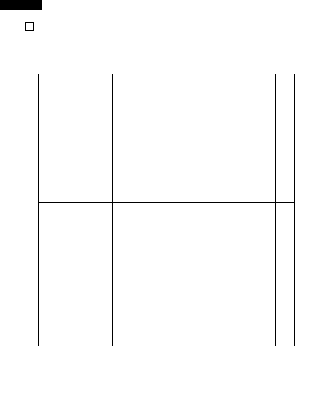
TROUBLESHOOTING
If a problem should arise,first check the following.
1. Are all connections correct ?
2. Have you operated the receiver according to the Operating Instructions ?
3. Are the speakers, turntable other components operating property ?
If this unit is not operating properly, check the items listed in the table below. Should the problem persist, there may be a malfunction.
Disconnect the power immediately and contact your store of purchase.
Symptom
DISPLAY not lit and sound not produced
when power operation switch set to on.
DISPLAY lit but sound not produced.
—
PROTECT
—
display appears.
Cause Measures
• Power cord not plugged in securely.
• Speaker cords not securely connected.
• Improper position of the audio function
button.
• Volume control set to minimum.
• MUTING is on.
• Speaker terminals are short-circuited.
• Block the ventilation holes of the set.
• The unit is operating at continuous high
power conditions and/or inadequate
ventilation.
• Check the insertion of the power cord plug.
• Turn the power on with the remote control
unit after turning the Power operation
switch on.
• Connect securely.
• Set to a suitable position.
• Turn volume up to suitable level.
• Switch off MUTING.
• Switch power off, connect speakers
properly, then switch power back on.
• Turn off the set’s power, then ventilate it
well to cool it down.
Once the set is cooled down, turn the
power back on.
• Turn off the set’s power, then ventilate it
well to cool it down.
Once the set is cooled down, turn the
power back on.
Sound produced only from one channel.
• Incomplete connection of speaker cords.
• Incomplete connection of input/output
cords.
• Connect securely.
• Connect securely.
Page
6
17
9, 10
18
18
22
9, 10
5
5
9, 10
6 ~ 8
Positions of instruments reversed during
stereo playback.
• Reverse connections of left and right
speakers or left and right input/output
cords.
• Check left and right connections. 6 ~ 10
Humming noise produced when record
is playing.
• Ground wire of turntable not connected
properly.
• Incomplete PHONO jack connection.
• TV or radio transmission antenna nearby.
• Connect securely.
• Connect securely.
• Contact your store of purchase.
6
6
–
Howling noise produced when volume is
high.
• Turntable and speaker systems too close
together.
• Floor is unstable and vibrates easily.
• Separate as much as possible.
• Use cushions to absorb speaker vibrations
transmitted by floor. If turntable is not
equipped with insulators, use audio
insulators (commonly available).
–
–
Sound is distorted.
• Stylus pressure too weak.
• Dust or dirt on stylus.
• Cartridge defective.
• Apply proper stylus pressure.
• Check stylus.
• Replace cartridge.
–
–
–
Volume is weak.
• MC cartridge being used. • Replace with MM cartridge or use a head
amplifier or step-up transformer.
6
This unit does not operate properly
when remote control unit is used.
• Batteries dead.
• Remote control unit too far from this unit.
• Obstacle between this unit and remote
control unit.
• Different button is being pressed.
• < and > ends of battery inserted in
reverse.
• Replace with new batteries.
• Move closer.
• Remove obstacle.
• Press the proper button.
• Insert batteries properly.
12
12
12
–
12
Common problems arising when listening to the
CD, records, tapes, and FM broadcasts, etc.
When playing records
Remote control unit.

29
ENGLISH
• Audio section
(Power amplifier)
Rated output: 100 W + 100 W (8 Ω/ohms, 20 Hz ~ 20 kHz with 0.05 % T.H.D.)
Output terminals: A or B 14 to 16 Ω/ohms
A+B 18 to 16 Ω/ohms
(Analog)
LINE input — PRE OUT
Input sensitivity/input impedance: 200 mV / 47 kΩ/kohms
Frequency response: 10 Hz ~ 50 kHz: ±1.5 dB
S/N ratio: 100 dB (IHF-A weighted)
Total harmonic distortion: 0.009 % (-3 dB at rated output,8 Ω/ohms) (1 kHz)
Rated output: 1.2 V
PHONO input — REC OUT
Input sensitivity/input impedance: 3.0 mV/47 kΩ /kohms
RIAA deviation: ±0.5 dB (20 Hz ~ 20kHz)
S/N ratio: 74 dB (IHF-A weighted, with 5 mV input)
Total harmonic distortion: 0.03 % (1 kHz, 3V)
Rated output/Maximum output: 150 mV / 7 V
• Video section
(standard video jacks)
Input/output level and impedance: 1 V p-p, 75 Ω/ohms
Frequency response: 5 Hz ~ 10 MHz +1, -3 dB
• Tuner section
[FM] (note:
µ
V at 75
Ω
/ohms, 0 dBf = 1 x 10
-15
W) [AM]
Receiving range: 87.50 MHz ~ 107.90 MHz 520 kHz ~ 1710 kHz
Usable sensitivity: 1.4 µV (14.2 dBf) 18 µV
50 dB quieting sensitivity: MONO 2.8
µ
V (20.2 dBf)
STEREO 23
µ
V (38.5 dBf)
S/N ratio: MONO 80 dB (IHF-A weighted)
STEREO 75 dB (IHF-A weighted)
Total harmonic distortion: MONO 0.15 % (1kHz)
STEREO 0.3 % (1kHz)
• General
Power supply: AC 120 V, 60 Hz
Power consumption: 3.4 A
Maximum external dimensions: 434 (W) x 171 (H) x 416 (D) mm (17-1/16” x 6-23/32” x 16-3/8”)
Weight: 10.0 kg (22 lbs)
• Remote control unit RC-872, RC-873
RC-872
Batteries: R6P/AA Type (two batteries)
External dimensions: 54 (W) x 172 (H) x 27.2 (D) mm (2-1/8” x 6-3/4” x 1-1/16”)
Weight: 100 g (Approx. 6 oz) (including batteries)
RC-873
Batteries: R03/AAA Type (two batteries)
External dimensions: 47.5 (W) x 127 (H) x 18 (D) mm (1-27/32” x 5 x 11/16”)
Weight: 70 g (Approx. 2.4 oz)
* For purposes of improvement, specifications and design are subject to change without notice.
13
SPECIFICATIONS
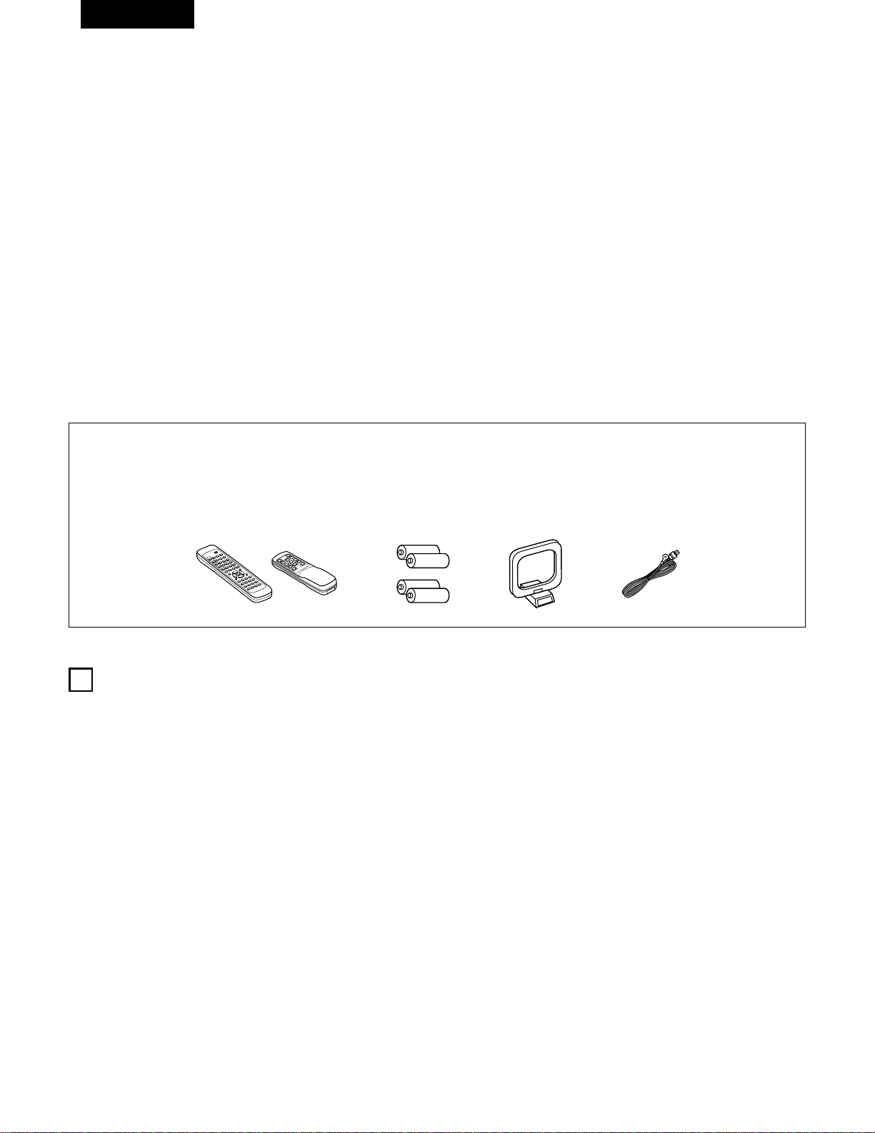
30
FRANCAIS
2 ACCESSOIRES
Vérifier que les articles suivants sont inclus dans le carton en plus de l’unité principale:
1
AVANT L‘UTILISATION
Faire attention au points suivants avant d’utiliser cet appareil:
q Mode d’emploi ……………………………………………………1
w Certificat de garantie ………………………………………………1
e Liste des centres d’entretien ……………………………………1
r Télécommande (RC-872) …………………………………………1
(RC-873
)
…………………………………………1
t Piles (R6P/AA) …………………………………………………2
(R03/AAA) ………………………………………………2
y Antenne-cadre AM…………………………………………………1
u Antenne intérieure FM ……………………………………………1
2 INTRODUCTION
Nous vous remercions d’avoir choisi le récepteur radio FM - AM stéréo DENON.
Ce remarquable composant a été fabriqué pour assurer une reproduction haute fidélité remarquable de vos sources musicales favorites.
Ce produit étant équipé d’une immense foule de caractéristiques, nous vous recommandons avant de commencer l’installation et l’utilisation de
l’appareil de bien lire le contenu de ce manuel avant de procéder.
TABLE DES MATIERES
z
Avant L’utilisation……………………………………………………30
x
Précautions D’installation …………………………………………31
c
Précautions de Manipulation ………………………………………31
v
Caractéristiques ……………………………………………………31
b
Connexions ……………………………………………………32~36
n
Nomenclature et Fonctions
……………………………………36, 37
m
Unité de Télécommande ………………………………………38~43
,
Opérations ………………………………………………………43~49
.
Ecouter de là Radio ……………………………………………50~52
⁄0
Initialisation du Microprocesseur …………………………………53
⁄1
Mémoire de Dernière Fonction …………………………………53
⁄2
Dépistage des Pannes ……………………………………………54
⁄3
Spécifications ………………………………………………………55
• Déplacement de l’appareil
Pour éviter des court-circuits ou des fils endommagés dans les
câbles de connexion, toujours débrancher le cordon d’alimentation,
et déconnecter les câbles de connexion entre tous les autres
composants audio lors du déplacement de l’appareil.
• Avant de mettre sous tension
Vérifier une nouvelle fois si toutes les connexions sont bonnes et
s’il n’y a pas de problèmes avec les câbles de connexion. Toujours
placer l’interrupteur de mise sous tension en position d’attente
avant de connecter et de déconnecter les câbles de connexion.
• Ranger ces instructions dans un endroit sûr
Après les avoir lues, ranger ces instructions en même temps que
la garantie dans un endroit sûr.
• Noter que les illustrations de ces instructions peuvent varier
de l’appareil actuel dans un but d’explication.
r
9
8
B
0
0
2
2
3
6
7
6
7
t yu
B
(RC-872) (RC-873)
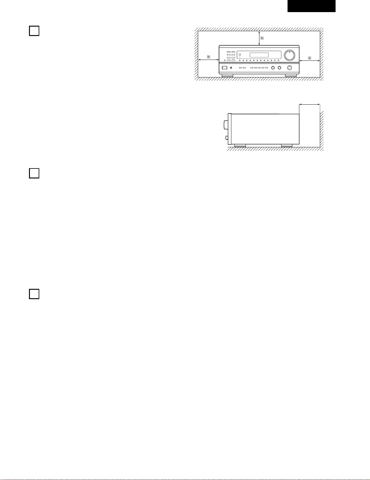
31
FRANCAIS
2
PRECAUTIONS D’INSTALLATION
3
PRECAUTIONS DE MANIPULATION
L’utilisation simultanée de cet appareil ou d’autres appareils
électroniques à microprocesseur avec un tuner ou un téléviseur peut
produire des parasites dans le son ou l’image.
Si cela se produit, prendre les mesures suivantes:
• Installer cet appareil aussi loin que possible du tuner ou du
téléviseur.
• Eloigner les câbles d’antenne du tuner ou du téléviseur aussi loin
que possible du cordon d’alimentation et des câbles de connexion
d’entrée/sortie de cet appareil.
• Ce problème est fréquemment rencontré lors de l’utilisation
d’antennes intérieures ou de câbles d’arrivée de 300 Ω/ohms.
L’utilisation d’antennes extérieures et de câbles coaxiaux de
75 Ω/ohms est recommandée.
Pour permettre la dissipation de la chaleur, laisser un espace
d’au moins 10 cm entre le haut, l’arrière et les flancs de cet
appareil et le mur ou d’autres composants.
• Commutation de la fonction d’entrée lorsque les prises
d’entrée ne sont pas connectées
Un déclic peut être produit si la fonction d’entrée est commutée
lorsque rien n’est connecté aux prises d’entrée. Dans ce cas,
abaisser la commende VOLUME ou connecter des composants
aux prises d’entrée.
• Mise en sourdine des prises de sortie préamplifiée (PRE OUT)
Les prises de sortie préamplifiée (PRE OUT) comprennent un
circuit de mise en sourdine. Pour cette raison, les signaux de
sortie sont fortement réduits pendant plusieurs secondes après
que l’interrupteur de mise sous tension ait été allumé. Si le volume
est augmenté pendant cet instant, la sortie sera très élevée après
l’arrêt du circuit de mise en sourdine. Toujours attendre que le
circuit de mise en sourdine se désactive avant de régler le volume.
• Chaque fois que l’interrupteur de mise sous tension est en
position STANDBY, l’appareil est toujours connecté à une
tension de ligne secteur.
Toujours débrancher le câble pour aller, par exemple, en
vacances.
4
CARACTERISTIQUES
1. Système d’équipement sonore dans plusieurs pièces (Multi
Room Music Entertainment System
Fonction avec des sources multiples :
La fonction multi-source de l’appareil vous permet de
sélectionner différentes sources audio et vidéo pour l’écoute ou
le visionnage, afin d’en profiter dans la salle principale et dans
une autre pièce au même moment. Cette nouvelle option vous
procure une souplesse d’utilisation inégalée, une fois que votre
système a été installé avec cet appareil. Le niveau de sortie,
réglable par télécommande, est équivalent à 1V, ce qui est assez
pour activer un amplificateur additionnel installé dans une autre
pièce.
2. Amplificateur puissant et modulable
Amplificateur de puissance de très haute qualité:
Une grande vitesse et des transistors à haute puissance sont
utilisés dans la configuration du circuit rationnel, ce qui témoigne
de l’avance technologique de DENON en matière d’amplificateurs,
et garantit une sortie du son aussi claire que puissante.
3. Architecture individualisée des signaux (Signal Level Divided
Construction - SLDC)
Les circuits fournissant les signaux de bas et haut niveau ont été
séparés dans des blocs différents, afin de maintenir l’influence
des signaux les uns sur les autres à l’absolu minimum.La
conception du châssis de cet appareil est appelé Architecture
individualisée des signaux (Signal Level Divided Construction -
SLDC). Les signaux en sortie sont plus purs qu’auparavant, ce
qui permet une reproduction des sons encore plus claire et
fidèle.
4. Fonctions de la télécommande
• Télécommande avec fonction de pré-mémorisation (RC-872) :
Cet appareil est équipé d’une télécommande dotée de la
fonction de pré-mémorisation. Les codes de contrôle à
distance pour tous les composants DENON contrôlables à
distance, tels que les lecteurs DVD, lecteur vidéo, télévision
...etc ainsi que ceux fabriqués par d’autres producteurs
importants sont déjà en mémoire.
• Télécommande du mode à sources multiples (RC-873) :
Cet appareil est équipé d’une télécommande dotée du mode à
sources multiples, qui commande les sorties des sources
multiples et commande également le récepteur pour choisir
les fonctions, trouver des stations pré-réglées, ou alors ajuster
le niveau du volume depuis une autre pièce.
B
10 cm ou plus
10 cm ou plus
Mur
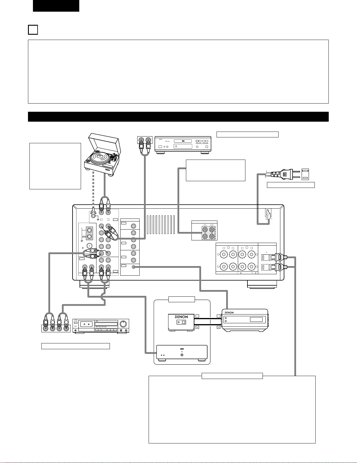
32
FRANCAIS
5
CONNEXIONS
• Ne pas brancher le cordon d’alimentation avant d’avoir terminé
toutes les connexions.
• Toujours connecter correctement les canaux de gauche et de
droite (gauche avec la gauche et droite avec la droite).
• Insérer fermement les fiches. Des connexions incomplètes
peuvent générer des parasites.
• N’utiliser les prises secteur (AC OUTLETS) que pour
l’équipement audio. Ne pas les utiliser pour un sèche-
cheveux, etc.
•
Remarquer que le groupement de cordons à fiches à broche
avec des cordons d’alimentation, ou le fait de les placer près
d’un transformateur provoque un bourdonnement ou un autre
bruit.
•
Un bruit ou un bourdonnement peut être généré si un
composant audio connecté est utilisé indépendamment sans
mettre cet appareil sous tension. Dans ce cas, mettre cet
appareil sous tension.
• Des parasites ou des bourdonnements peuvent se produire si un
des composants est utilisé de matière autonome sans que cet
appareil ne soit allumé. Si cela se produit, allumez cet appareil.
Connexion des composants audio
L
R
L
R
R LR L
R L
R L
R L
R L
+
-
+
-
SPEAKER SYSTEMS
IMPEDANCE A or B : 4 16 A
+
B : 8 16
VIDEO
PRE OUT
MAIN IN
B A
SWITCHED
TOTAL 120W
(
1A.
)
MAX.
120V 60Hz
AC OUTLETS
AUDIO
AUDIO
OUT
IN
OUT
OUT
IN
OUT
IN
DVD
/
VDP
VCR
MULTI
SOURCE
MULTI
SOURCE
ANTENNA
V.AUX
MONITOR
PHONO
CD
V.AUX
VCR
DVD
/
VDP
TAPE
VCRVCR
TAPE
ROOM TO ROOM
(
REMOTE CONTROL
)
SIGNAL
GND
LOOP
ANT.
AM
FM
COAX.
75
LINE IN
LINE OUT
LINE OUT
R
INPUTOUTPUT
LRL
L
R
L
R
L
R
L
R
R
OUTPUT
L
R
L
++
R
L
INPUT
OUTPUT
AUX OUT
LINE IN
DIGITAL AUDIODIGITAL AUDIO
Platine tourne-disque
(cellule à bobine mobile MM)
Fil de mise à la terre
Platine cassette
Lecteur de CD
REMARQUE:
Cet appareil ne peut pas
être utilisé directement
avec les cellules à bobine
mobile (MC). Utiliser un
amplificateur de tête
séparé ou un transfor-
mateur survolteur.
Connexion d’un lecteur de CD
Connecter les prises de sortie analogique (ANALOG
OUTPUT) du lecteur de CD aux prises CD de cet
appareil en utilisant les cordons à fiches à broche.
Utiliser ces prises lors de l’utilisation
d’un pré-amplificateur principal ou
d’un amplificateur séparé.
120 V CA 60 Hz
PRISES SECTEUR
• Prises commutées (SWITCHED) (capacité totale 120 W (1 A.))
L’alimentation de ces prises est activée et désactivée par l’interrupteur de mise sous
tension (POWER) situé sur l’unité principale. Ces prises sont également commutées
lorsque l’alimentation est mise en veille (ON-STANDBY) à l’aide de la télécommande.
Aucune alimentation électrique n’est fournie par ces prises quand l’alimentation de
l’appareil est en mode d’attente (standby). Ne jamais connecter d’équipement dont la
capacité totale est supérieure à 120 W (1 A).
REMARQUE:
N’utiliser les prises secteur (AC OUTLETS) que pour l’équipement audio. Ne pas les
utiliser pour un sèche-cheveux, etc.
Connexion des prises secteur
Connexion d’une platine cassette
Connexions pour l’enregistrement:
Connecter les prises d’entrée d’enregistrement
(LINE IN ou REC) de la platine cassette aux
prises de sortie (OUT) d’enregistrement de
cassette de cet appareil en utilisant les cordons
à fiches à broche.
Connexions pour la lecture:
Connecter les prises de sortie de lecture (LINE
OUT ou PB) de la platine cassette aux prises
d’entrée (IN) de lecture de cassette de cet
appareil en utilisant les cordons à fiches à
broche.
Prises de sortie préamplifiée
(PRE OUT)
Prises de entrée principale
(MAIN IN)
Cordon d’alimentation
RC-617 (Vendue séparément)
DETECTEUR INFRAROUGE
Amplificateur de puissance
RC-616 (Vendue séparément)
RE-EMETTEUR INFRAROUGE
Autre pièce
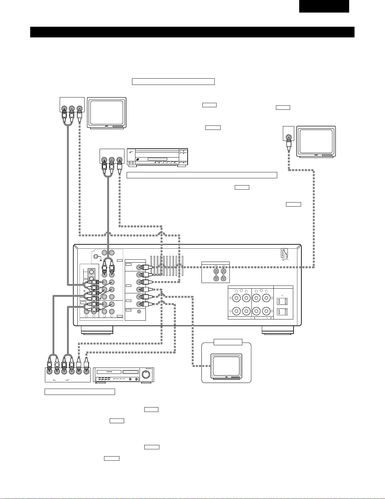
33
FRANCAIS
Connexion des composants vidéo
• Pour connecter le signal vidéo, connecter en utilisant un câble de signal vidéo de 75 Ω/ohms. L’utilisation d’un mauvais câble peut entraîner
une baisse de la qualité du son.
• Lors des connexions, se reporter également aux instructions d’utilisation des autres composants.
R LR L
R L
R L
R L
R L
+
-
+
-
SPEAKER SYSTEMS
IMPEDANCE A or B : 4 16 A
+
B : 8 16
VIDEO
PRE OUT
MAIN IN
B A
SWITCHED
TOTAL 120W
(
1A.
)
MAX.
120V 60Hz
AC OUTLETS
AUDIO
AUDIO
OUT
IN
OUT
OUT
IN
OUT
IN
DVD
/
VDP
VCR
MULTI
SOURCE
MULTI
SOURCE
ANTENNA
V.AUX
MONITOR
PHONO
CD
V.AUX
VCR
DVD
/
VDP
TAPE
VCRVCR
TAPE
ROOM TO ROOM
(
REMOTE CONTROL
)
SIGNAL
GND
LOOP
ANT.
AM
FM
COAX.
75
AUDIO OUT
VIDEO OUT
AUDIO IN
AUDIO OUT
VIDEO OUT
VIDEO IN
VIDEO OUT
VIDEO IN
AUDIO OUT
IN
VIDEO
ROUT
VIDEO
OUT
L
AUDIO
L
R
R OUT
VIDEO
OUT
L
AUDIO
R
L
R
L
R
L
L
R
R OUT IN
AUDIO
VIDEO
OUT IN
LRL
R
L
R
L
VIDEO IN
L
R
Connexion d’un téléviseur/tuner DBS
Téléviseur/DBS
• Connecter la prise de sortie vidéo (VIDEO OUTPUT) du
téléviseur ou du tuner DBS à la prise d’entrée de
téléviseur/tuner DBS (TV/DBS IN) (jaune) en utilisant
un cordon à fiches à broche coaxial vidéo de 75 Ω/ohms.
• Connecter la prise de sortie audio (AUDIO OUTPUT) du
téléviseur ou du tuner DBS à la prise d’entrée de
téléviseur/tuner DBS (TV/DBS IN) en utilisant des
cordons à fiches à broche.
AUDIO
VIDEO
Téléviseur ou tuner
DBS
Lecteur de LD (VDP) ou lecteur de DVD
Magnétoscope
Moniteur de téléviseur
Prise de sortie de moniteur
(MONITOR OUT)
• Connecter la prise d’entrée vidéo
(VIDEO INPUT) du téléviseur à la prise
de sortie de moniteur (MONITOR OUT)
en utilisant un cordon à fiches
à broche coaxial vidéo de 75 Ω/ohms.
VIDEO
Connexion d’un lecteur de vidéo disque (VDP) ou d’un lecteur de DVD
• Connecter la prise de sortie vidéo (VIDEO OUTPUT) du lecteur de vidéo disque (lecteur de
DVD) à la prise d’entrée de DVD/VDP (DVD/VDP IN) (jaune) en utilisant un cordon
à fiches à broche coaxial vidéo de 75 Ω/ohms.
• Connecter la prise de sortie audio analogique (ANALOG AUDIO OUTPUT) du lecteur de
vidéo disque (lecteur de DVD) à la prise d’entrée de DVD/VDP (DVD/VDP IN) en
utilisant des cordons à fiches à broche.
AUDIO
VIDEO
Connexion des magnétoscopes
Connexions d’entrée/sortie vidéo:
• Connecter la prise de sortie vidéo (VIDEO OUT) du magnétoscope à
la prise d’entrée de magnétoscope (VCR IN) (jaune) et la
prise d’entrée vidéo (VIDEO IN) du magnétoscope à la prise de sortie
de magnétoscope (VCR OUT) (jaune) en utilisant les cordons
à fiches à broche coaxial vidéo de 75 Ω/ohms.
Connexion des prises de sortie audio
• Connecter les prises de sortie audio (AUDIO OUT) du magnétoscope
aux prises d’entrée de magnétoscope (VCR IN) et les prises
d’entrée audio (AUDIO IN) du magnétoscope aux prises de sortie de
magnétoscope (VCR OUT) en utilisant des cordons à fiches
à broche.
AUDIO
AUDIO
VIDEO
VIDEO
Moniteur de téléviseur
Autre pièce
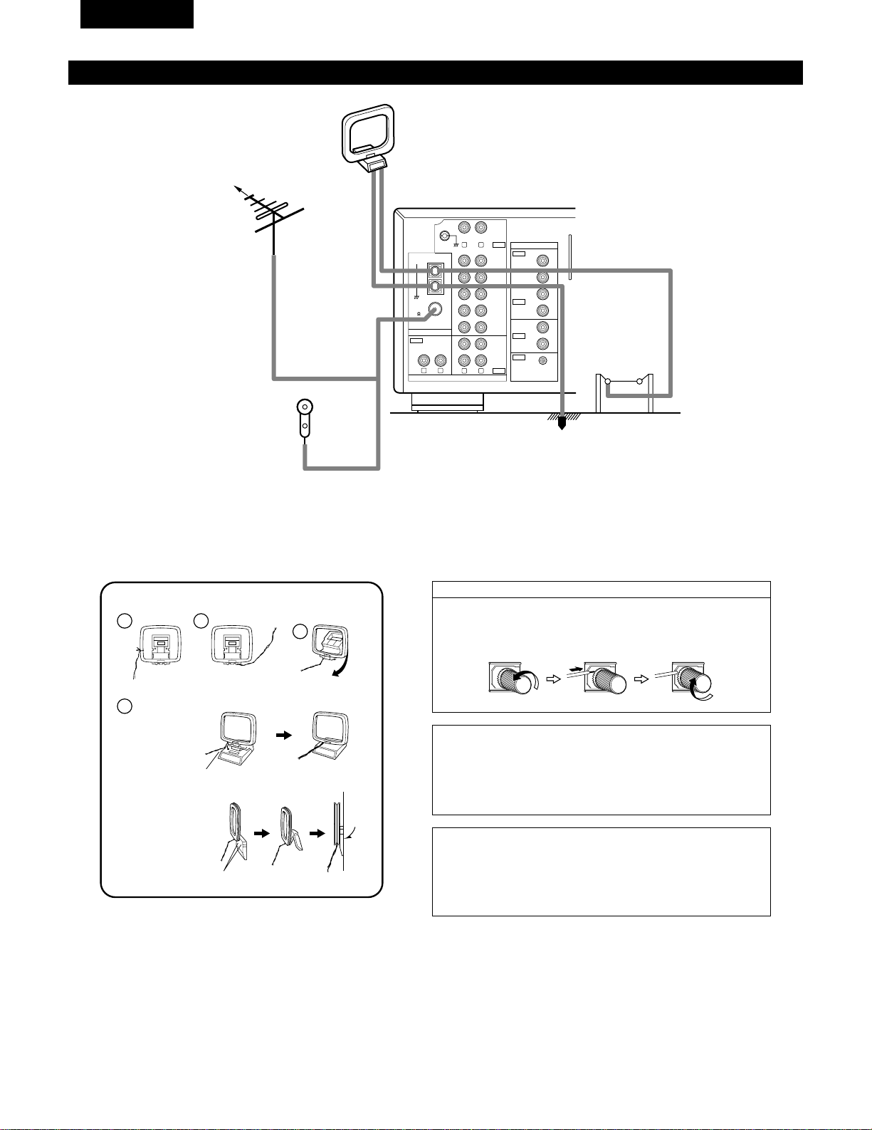
34
FRANCAIS
Connexion des bornes d’antennes
R L
R L
R L
VIDEO
AUDIO
OUT
IN
OUT
OUT
IN
OUT
IN
DVD
/
VDP
VCR
MULTI
SOURCE
MULTI
SOURCE
ANTENNA
V.AUX
MONITOR
PHONO
CD
V.AUX
VCR
DVD
/
VDP
TAPE
VCRVCR
TAPE
ROOM TO ROOM
(
REMOTE CONTROL
)
SIGNAL
GND
LOOP
ANT.
AM
FM
COAX.
75
DIRECTION DE
STATION DE
RADIODIFFUSION
ANTENNE FM
CABLE
COAXIAL DE
75 Ω/ohms
Antenne intérieure FM
(Accessoire)
ANTENNE-CADRE AM
(Accessoire)
ANTENNE
EXTERIEURE
AM
TERRE
1
4
2
3
Ensemble d’antenne-cadre AM
Connecter aux
bornes d’antenne AM.
Plier dans la
direction inverse.
Défaire le noeud en
vinyle et sortir la
ligne de connexion.
a. Avec l’antenne sur
le haut de toute
surface stable.
b. Avec l’antenne
fixée au mur.
Trou d’installation
Monter au mur, etc.
Monter
Remarque à l’installateur de système de télédistribution:
Ce rappel est fourni pour attirer l’attention de l’installateur de système
de télédistribution sur l’article 820-40 du NEC qui fournit des directives
sur une bonne mise à la masse et, en particulier, spécifie que la terre du
câble doit être connectée au système de mise à la masse du bâtiment,
aussi près du point d’entrée de câble que possible.
Remarques:
• Ne pas connecter simultanément deux antennes FM.
• Même si une antenne extérieure AM est utilisée, ne pas déconnecter
l’antenne-cadre AM.
• Vérifier que les bornes de fil d’antenne-cadre AM ne touchent pas les
parties métalliques du panneau.
Connexion des antennes AM
1. Desserrer en tournant
dans le sens contraire
des aiguilles d’une
montre.
2. Insérer le cordon. 3. Serrer en tournant dans
le sens des aiguilles
d’une montre.
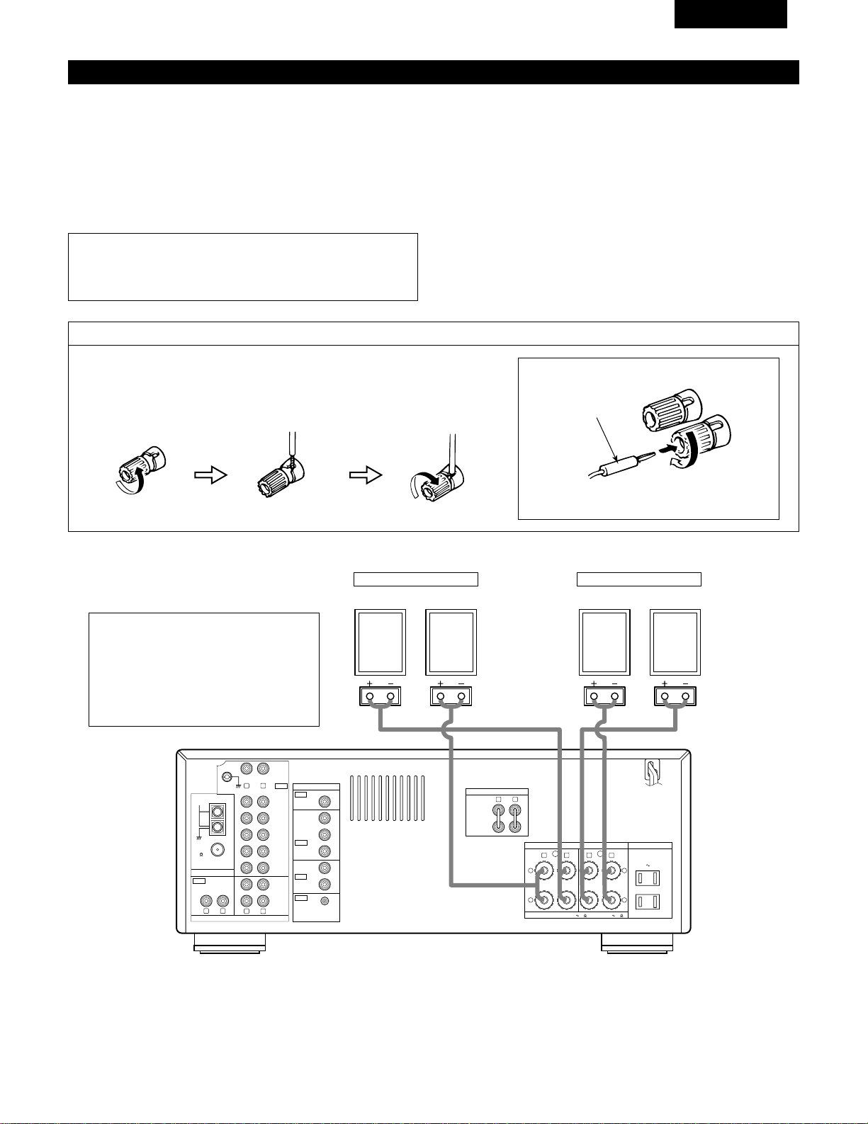
35
FRANCAIS
Connexions du système d’enceintes
• Connecter les bornes d’enceinte aux enceintes en respectant les
polarités (
<
au
<
,
>
au
>
). Si les polarités ne sont pas
respectées, un son central faible est entendu, l’orientation des
divers instruments n’est pas correcte et le sens de la direction du
son stéréo est détérioré.
• Lors de la réalisation des connexions, prendre soin de ne mettre
en contact aucun des conducteurs individuels du cordon
d’enceinte avec des bornes adjacentes, avec des conducteurs
d’autres cordons d’enceinte ou avec le panneau arrière.
Impédance d’enceinte
• Lorsque des systèmes d’enceinte A et B sont utilisés séparément,
les enceintes ayant une impédance de 4 à 16 Ω/ohms peuvent
être connectées pour une utilisation comme enceintes.
• Faites attention en cas d’utilisation de 2 paires d’enceintes (A+B)
en même temps, puisque il faut utiliser des enceintes avec des
impédances entre 8 et 16 Ω/ohms.
• Le circuit de protection peut être activé si le système est reproduit
pendant une longue durée à un volume élevé lorsque des
enceintes d’une impédance inférieure à celle spécifiée sont
connectées.
REMARQUE:
NE JAMAIS toucher les bornes d’enceinte lorsque l’ampli est
sous tension, sinon des décharges électriques risquent de se
produire.
Connexion des bornes d’enceinte
1. Tourner dans le sens
contraire des aiguilles
d’une montre pour la
desserrer.
2. Insérer le cordon. 3. Tourner dans le sens
des aiguilles d’une
montre pour la
resserrer.
Connexion des fiches bananes
Fiche banane
Tourner dans le sens des aiguilles d’une montre pour
serrer, puis insérer la fiche banane.
(
L
) (
R
)(
L
) (
R
)
R LR L
R L
R L
R L
R L
+
-
+
-
SPEAKER SYSTEMS
IMPEDANCE A or B : 4 16 A
+
B : 8 16
VIDEO
PRE OUT
MAIN IN
B A
SWITCHED
TOTAL 120W
(
1A.
)
MAX.
120V 60Hz
AC OUTLETS
AUDIO
AUDIO
OUT
IN
OUT
IN
OUT
IN
DVD
/
VDP
VCR
MULTI
SOURCE
MULTI
SOURCE
ANTENNA
V.AUX
MONITOR
PHONO
CD
V.AUX
VCR
DVD
/
VDP
TAPE
VCRVCR
TAPE
ROOM TO ROOM
(
REMOTE CONTROL
)
SIGNAL
GND
LOOP
ANT.
AM
FM
COAX.
75
• Précautions à prendre lors de la connexion
des enceintes
Si une enceinte est placée près d’un téléviseur
ou d’un moniteur vidéo, les couleurs de l’écran
peuvent être perturbées par le magnétisme de
l’enceinte. Si cela se produit, déplacer
l’enceinte vers un endroit où cet effet ne se
produit pas.
Système B
SYSTEME D’ENCEINTES
Système A
SYSTEME D’ENCEINTES
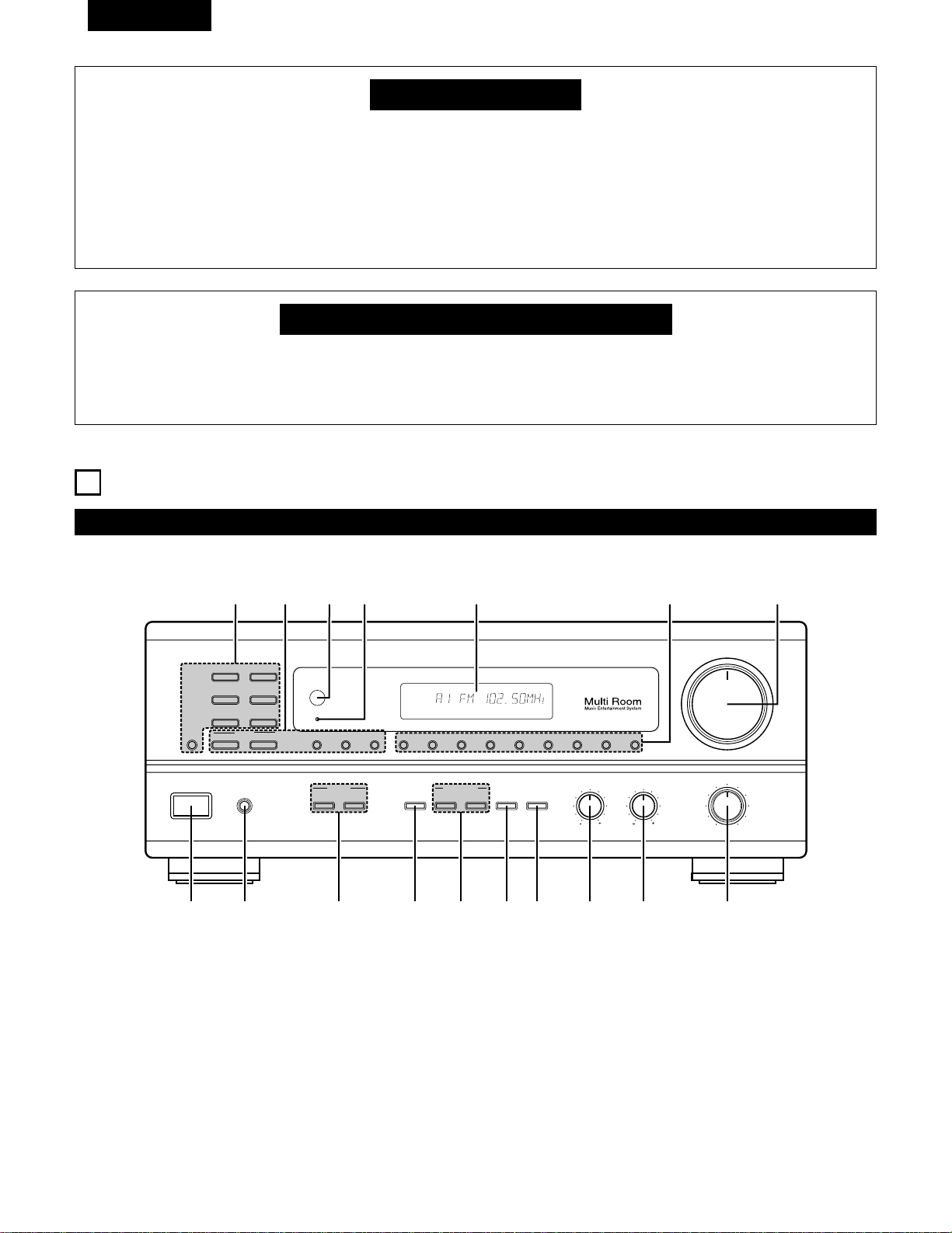
36
FRANCAIS
Circuit de protection
•
Cet appareil est doté d’un circuit de protection à haute vitesse. Ce circuit protège les circuits internes de tout
endommagement éventuel dû à l’afflux de courants importants lorsque les prises d’enceinte ne sont pas complètement
connectées ou lorsqu’une sortie est générée par un court-circuit.
Dans un tel cas, le circuit de protection fonctionne pour couper la sortie aux enceintes. Si cela se produit, éteindre
l’appareil et vérifier les connexions d’enceinte. Ensuite, mettre à nouveau l’appareil sous tension. Après un silence de
quelques secondes, le rècepteur devrait fonctionner normalement.
Si le circuit de protection est à nouveau activé bien qu’il n’y ait pas de problème de câblage ou de ventilation autour de
l’appareil, couper l’alimentation, et contacter un centre d’entretien DENON.
Remarque sur l’impédance des enceintes
•
Le circuit de protection peut être activé si l’appareil est utilisé pendant une longue durée à un volume élevé lorsque des
enceintes d’une impédance inférieure à celle spécifiée (par exemple, enceintes ayant une impédance inférieure à 4
Ω/ohms) sont connectées. Si le circuit de protection est activé, la sortie des enceintes est coupée. Couper l’alimentation
de l’appareil, attendre qu’il refroidisse, améliorer la ventilation autour de lui, puis remettre sous tension.
6
NOMENCLATURE ET FONCTIONS
Panneau avant
• Pour les détails sur les fonctions de ces pièces, se reporter aux pages données entre parenthèses ( ).
VOLUME
MODEBAND SHIFTMEMORY 12345678
STANDBY
REMOTE
SENSOR
B
PHONES
ON / STANDBY
BALANCE
MULTI SOURCE
LOUDNESS
MODE
SELECT
VIDEO
SELECT
A
B
TONE
DEFEAT
SPEAKER
BASS TREBLE
LR
DRA-685
PRECISION AUDIO COMPONENT / AM-FM STEREO RECEIVER
TUNING
UPDOWN
PHONO
TUNER
VCR
CD
DVD / VDP
V. AUX
TAPE
MONITOR
!7 !6 !5
!4
!3
!1!2
!0oiuytrewq
AUTO CH
TONE SP-A TUNER
q
Interrupteur de mise en marche ………………………………(43)
w
Prise de casque d’écoute (PHONES) …………………………(48)
e
Touches SPEAKER A/B …………………………………………(43)
r
Touche VIDEO SELECT …………………………………………(48)
t
Touches MULTI SOURCE …………………………………(45, 46)
y
Touche TONE DEFECT …………………………………………(44)
u
Touche LOUDNESS ………………………………………………(44)
i
Commande de réglage de graves (BASS) ……………………(44)
o
Commande de réglage des aigus (TREBLE) ………………(44)
!0
Commande BALANCE……………………………………………(44)
!1
Commande VOLUME ……………………………………………(44)
!2
Touches de sélection de mémoire préréglée ……………(52)
!3
Affichage
!4
Témoin d’alimentation ……………………………………………(43)
!5
Capteur de télécommande (REMOTE SENSOR) ……………(38)
!6
Touches TUNING ……………………………………………(51, 52)
!7
Touches de sélection de source d’entrée ……………………(44)
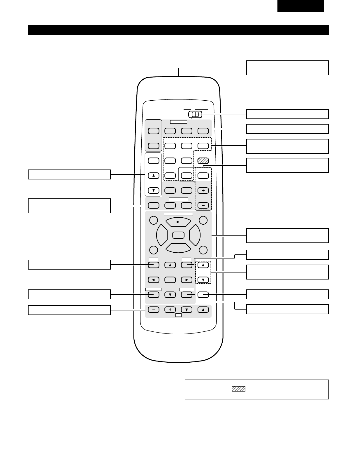
37
FRANCAIS
Unité de télécommande (RC-872)
• Pour les détails sur les fonctions de ces pièces, se reporter aux pages données entre parenthèses ( ).
98
B
CD DVD/VDP
VCR
V.AUX
TUNER
SHIFT
REMOTE CONTROL UNIT RC-872
VOLUME
CHANNEL
DISPLAY
MUTING
TITLE
DISC SKIP+
MULTI
MULTI
VOL.
TAPE
MONITOR
CD·MD/CDR·DVD/VDP
TV
SET UP
SELECT
MENU
CHANNEL
ON
OFF
RECEIVER
DVD/VDP
TV VCR
PHONO
0
0
2
2
3
AUDIO
CD
MD/CD-R
VIDEO
POWER
DECK
·
VCR
6
7
6
7
VIDEO SELECT
SP-A SP-B
STATUS
RETURN
VOLUME
Touche VIDEO SELECT ………………(48)
Emetteur de signaux
de télécommande ……………………(38)
Touches POWER …………………(42, 43)
Touches de commande
VOLUME ………………………………(44)
Touche MUTING ………………………(48)
Touches de système (TV) ……………(42)
Touche STATUS ………………………(49)
Touches de système
(CD, MD/CD-R, DVD/VDP) ………(39, 42)
Sélecteur de mode ………………(39, 40)
Sélecteurs de source
d’entrée …………………………………(44)
Touche SPEAKER B……………………(43)
Touches de sélection de
mémoire préréglée ……………………(52)
Touche SPEAKER A……………………(43)
Touches MULTI SOURCE ………(45, 46)
Touches de système
(DECK, VCR) ………………………(39, 42)
REMARQUE:
• Les touches rayées ne fonctionnent pas avec le cet appareil.
(Rien ne se passe lorsqu
’elles sont enfoncées.
)
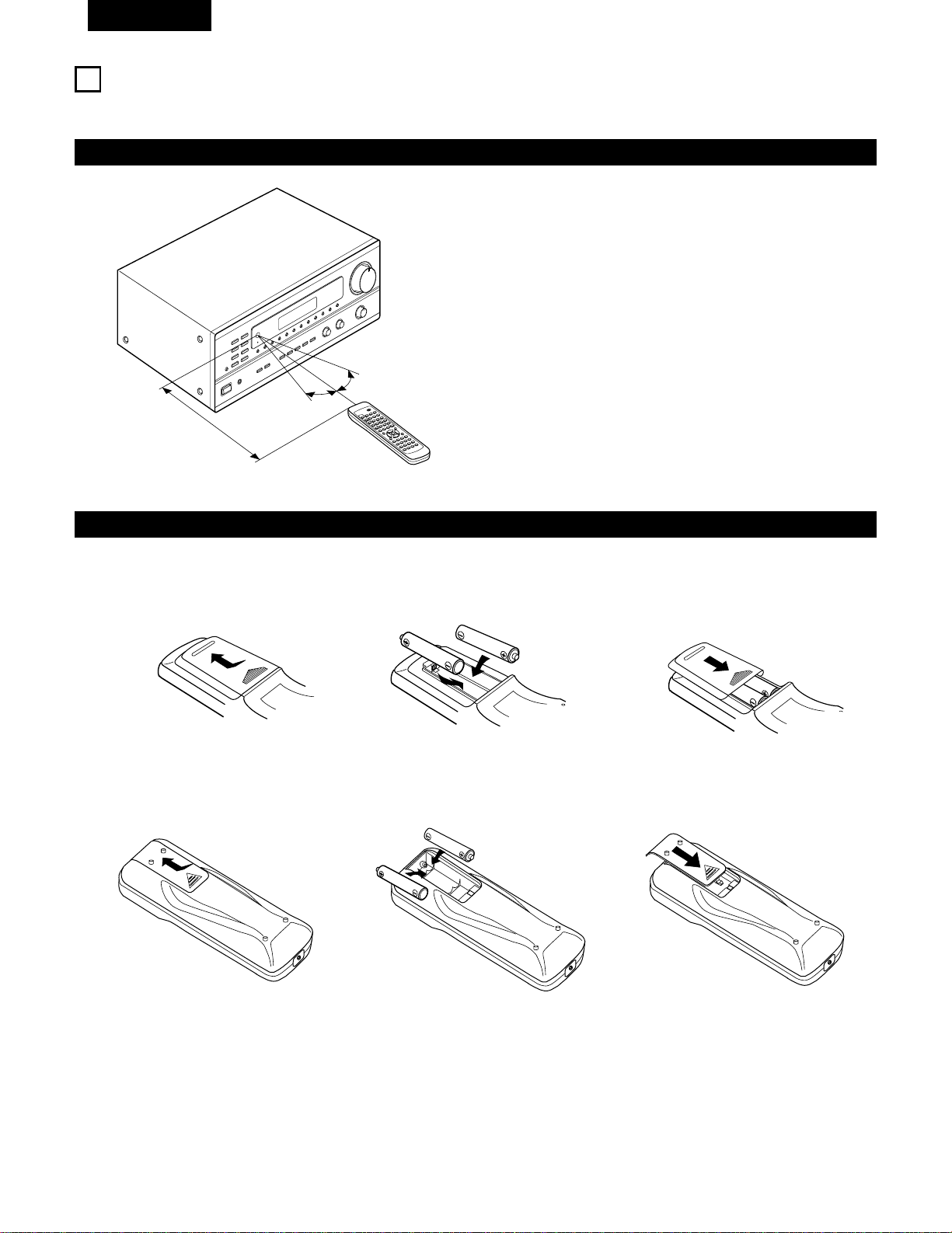
38
FRANCAIS
7
UNITE DE TELECOMMANDE
En suivant la procédure expliquée ci-dessous, insérer les piles avant d’utiliser la télécommande.
Plage d’utilisation de la télécommande
Insertion des piles
Diriger la télécommande vers le détecteur de télécommande de la
manière indiquée sur le diagramme de gauche.
REMARQUES:
• La télécommande peut être utilisée à une distance directe
d’environ 7 m, mais cette distance diminue ou le fonctionnement
devient difficile s’il y a des obstacles entre la télécommande et le
détecteur de télécommande, si le détecteur de télécommande est
exposé à la lumière directe du soleil ou à une autre lumière forte,
ou si elle est actionnée d’un angle.
• Des enseignes au néon ou autres dispositifs émettant des
parasites type impulsion à proximité peuvent entraîner un mauvais
fonctionnement, par conséquent garder l’appareil aussi loin que
possible de ces dispositifs.
B
9
8
B
0
0
2
2
3
6
7
6
7
Approx. 7 m/23 pieds
q Appuyer de la manière indiquée par la
flèche, et retirer en glissant.
w Insérer correctement les piles R6P/AA de
la manière indiquée sur le diagramme.
e Refermer le couvercle.
REMARQUES:
• Vérifier que les polarités sont correctes. (Voir l’illustration à l’intérieur du compartiment à piles.)
• Retirer les piles si l’émetteur de la télécommande n’est pas utilisé pendant une longue période.
• Si des piles fuient, les jeter immédiatement. Eviter de toucher le matériel fuyant ou de le laisser entrer en contact avec un vêtement, etc.
Nettoyer à fond le compartiment à piles avant de mettre de nouvelles piles en place.
• Même si moins d’un an s’est écoulé, remplacer les piles par des neuves si l’appareil ne fonctionne pas lorsque l’unité de télécommande est
actionnée à proximité. (La pile fournie ne sert que pour la vérification du fonctionnement. La remplacer par une neuve le plus tôt possible.)
• Au moment du remplacement des piles, après les avoir retiré, attendre environ une minute avant d’en insérer de nouvelles.
30°
30°
Pour télécommande (RC-872)
Pour télécommande multi-source (RC-873)
q Appuyer de la manière indiquée par la
flèche, et retirer en glissant.
w Insérer correctement les piles R03/AAA
de la manière indiquée sur le diagramme.
e Close the lid.
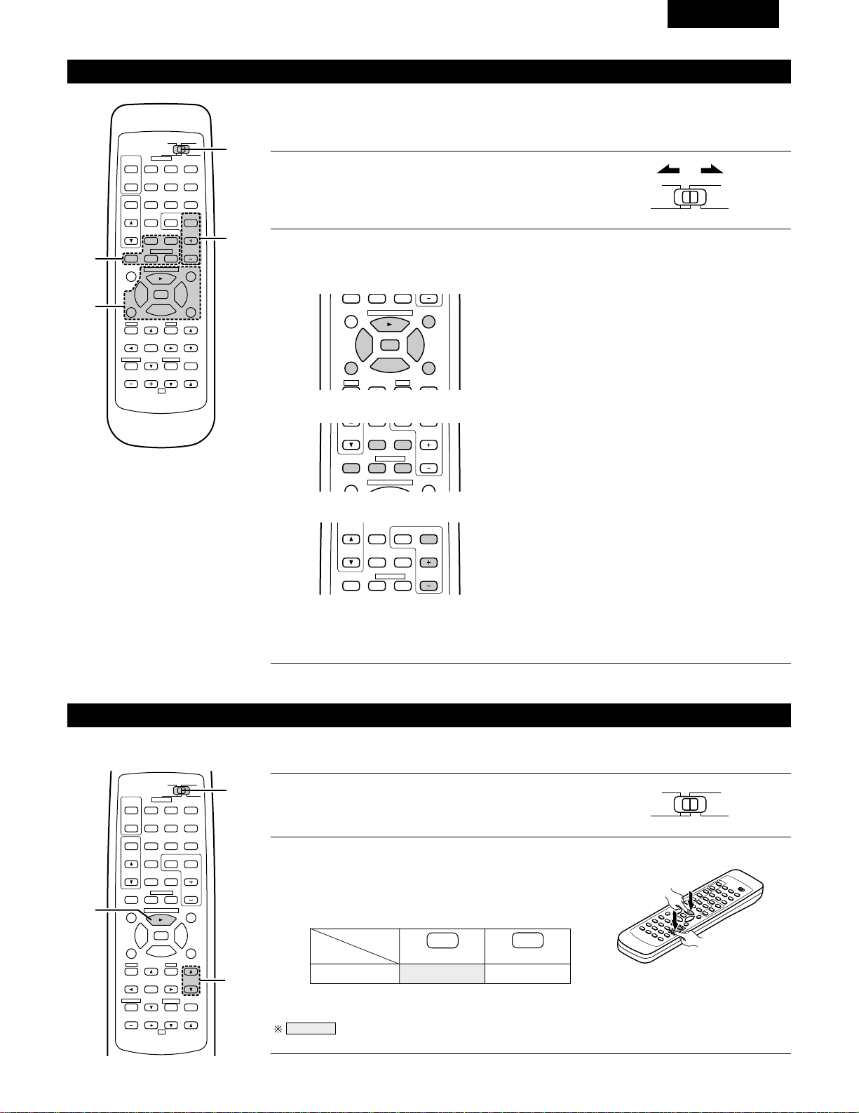
39
FRANCAIS
MD
Utilisation des composants audio DENON
Les composants audio télécommandables DENON peuvent être contrôlés en utilisant la télécommande
de cet appareil. Cependant, remarquer que certains composants ne peuvent pas être actionnés avec
cette télécommande.
2
Utiliser les touches indiquées ci-dessous pour actionner le composant audio.
Pour les détails, se reporter au mode d’emploi du composant respectif.
1
Régler le commutateur coulissant vers la position du
composant à actionner (CD ou MD/CD-R).
AUDIO
CD
MD/CD-R
VIDEO
98
TITLE
DISC SKIP+
CD·MD/CDR·DVD/VDP
0
0
2
2
3
6
7
SP-A SP-B
DISC SKIP+
MULTI
VOL.
CD·MD/CDR·DVD/VDP
CHANNEL
0
0
2
DECK
·
VCR
6
7
a. Pour lecteur CD et MD/CD-R
b. Pour platine cassette (DECK)
6,7 : Recherche manuelle (en arrière et en avant)
2 : Arrêt
1 : Lecture
8,9 : Recherche automatique
3 : Pause
DISC : Sélection de disque
SKIP+ (Uniquement changeur de CD)
6 : En Arrière
7 : En Avant
2 : Arrêt
1 : Lecture en avant
0 : Lecture en arrière
98
B
CD DVD/VDP
VCR
V.AUX
TUNER
SHIFT
REMOTE CONTROL UNIT RC-872
VOLUME
CHANNEL
DISPLAY
MUTING
VOLUME
TITLE
DISC SKIP+
MULTI
MULTI
VOL.
TAPE
MONITOR
CD·MD/CDR·DVD/VDP
TV
SET UP
SELECT
MENU
CHANNEL
ON
OFF
RECEIVER
DVD/VDP
TV VCR
PHONO
0
0
2
2
3
AUDIO
CD
MD/CD-R
VIDEO
POWER
DECK
·
VCR
6
7
6
7
VIDEO SELECT
SP-A SP-B
STATUS
RETURN
2-b
2-a
2-c
1
TUNER SHIFT
MULTI
VOL.
TAPE
MONITOR
CHANNEL
0
0
2
DECK
·
VCR
6
7
c. Pour TUNER
SHIFT : Changer la plage de canaux préréglés
CHANNEL : Augmentation/diminution
+, – de canal préréglé
REMARQUES:
• La platine cassette (DECK) et TUNER peut être utilisée lorsque le commutateur est sur la position
“AUDIO”.
Mémoire préréglée (Composants audio)
Les composants DENON peuvent être actionnés en réglant la mémoire pré-réglée sur MD ou CD-R.
98
B
CD DVD/VDP
VCR
V.AUX
TUNER
SHIFT
REMOTE CONTROL UNIT RC-872
VOLUME
CHANNEL
DISPLAY
MUTING
VOLUME
TITLE
DISC SKIP+
MULTI
MULTI
VOL.
TAPE
MONITOR
CD·MD/CDR·DVD/VDP
TV
SET UP
SELECT
MENU
CHANNEL
ON
OFF
RECEIVER
DVD/VDP
TV VCR
PHONO
0
0
2
2
3
AUDIO
CD
MD/CD-R
VIDEO
POWER
DECK
·
VCR
6
7
6
7
VIDEO SELECT
SP-A SP-B
STATUS
RETURN
2
1
2
1
Régler le commutateur coulissant vers “MD/CD-R”.
AUDIO
CD
MD/CD-R
VIDEO
2
Tout en maintenant enfoncé le bouton de lecture (PLAY),
appuyer sur le bouton du composant que vous souhaitez
régler. (Se reporter au tableau 1.)
B
REMARQUES:
•
La mémoire ne peut être préréglée que pour le MD ou le CD-R.
Codes préréglés réglés à la livraison de l’usine et lorsque réinitialisés.
VOLUME
CD-R
PLAY (1)
•
ª
Tableau 1: Combinaisons des codes de
système personnels
VOLUME

40
FRANCAIS
DENON A
Mémoire préréglée (Composants vidéo)
DENON et d’autres fabricants de composants peuvent être actionnés en réglant la mémoire préréglée de votre fabricant de composant vidéo.
L’opération n’est pas possible pour certains modèles.
1
Régler le commutateur coulissant vers “VIDEO”.
3
A présent, tout en maintenant la touche POWER
(alimentation) enfoncée, appuyer sur la touche du code
dans le bloc B. (Se reporter au tableau 2.)
4
Pour continuer l’enregistrement d’autres composants, répéter les étapes 2 à 3.
B
AUDIO
CD
MD/CD-R
VIDEO
2
Tout en maintenant enfoncé le touche POWER du
composant (DVD/VDP. VCR ou TV) que vous voulez
mettre en place, appuyer sur la touche du fabriquant
correspondant dans le bloc A. (Se reporter au tableau 2.)
B
Cette télécommande peut être utilisée pour actionner des composants d’autres fabricants sans utiliser la fonction de programmation en
enregistrant le nom du fabricant du composant de la manière indiquée de la manière indiquée dans le tableau 2.
Tableau 2: Combinaisons des codes de système personnels pour différents fabricants
“DVD”
A
B
—
—
—
—
—
—
—
—
—
—
—
—
—
—
—
98
B
CD DVD/VDP
VCR
V.AUX
TUNER
SHIFT
REMOTE CONTROL UNIT RC-872
VOLUME
CHANNEL
DISPLAY
MUTING
VOLUME
TITLE
DISC SKIP+
MULTI
MULTI
VOL.
TAPE
MONITOR
CD·MD/CDR·DVD/VDP
TV
SET UP
SELECT
MENU
CHANNEL
ON
OFF
RECEIVER
DVD/VDP
TV VCR
PHONO
0
0
2
2
3
AUDIO
CD
MD/CD-R
VIDEO
POWER
DECK
·
VCR
6
7
6
7
VIDEO SELECT
SP-A SP-B
STATUS
RETURN
B
1
2,3
A
0
1
6
7
2
MASTER VOL.
MUTING
ª
—
DENON B
—
—
—
—
—
—
—
—
—
—
—
—
—
—
—
—
PANASONIC
—
—
—
SONY
PIONEER
TOSHIBA
—
—
—
—
DVD/VDP
MULTI
VCR
MULTI VOL. •
TAPE MONITOR
TUNER
SHIFT
MULTI VOL. ª
TAPE
TAPE
TUNER
TAPE
TAPE
TAPE
—
“VDP”
A
B
DENON C
—
—
—
—
—
—
—
—
—
—
—
—
—
—
DENON B
—
—
—
—
—
—
—
—
—
—
—
—
—
—
DENON A
MITUBISHI
PANASONIC
—
SONY
PIONEER
—
—
—
—
PHILIPS
RCA
—
MAGNAVOX
+
TUNER
MASTER VOL.
•
MASTER VOL.
MUTING
ª
MASTER VOL.
•
0
1
6
7
2
DVD/VDP
MULTI
VCR
MULTI VOL. •
TAPE MONITOR
TUNER
SHIFT
MULTI VOL. ª
TAPE
TAPE
TUNER
TAPE
TAPE
TAPE
+
TUNER
REMARQUES:
•
La mémoire ne peut être préréglée que pour le DVD ou le VDP.
Codes préréglés réglés à la livraison de l’usine et lorsque réinitialisés.

41
FRANCAIS
REMARQUES:
• Les signaux des touches enfoncées sont émis pendant le réglage de la mémoire préréglée. Pour éviter une opération accidentelle,
recouvrir la fenêtre d’émission de la télécommande pendant le réglage de la mémoire préréglée.
• Certains modèles et années de fabrication de composants des fabricants énumérés dans le tableau 2 ne peuvent pas être utilisés.
• L’appareil est pourvu de différents types de codes de télécommandes, lesquels varient en fonction du constructeur. Si la télécommande
ne fonctionne pas lorsque le réglage est fait sur A, régler sur B ou C et essayer à nouveau.
HITACHI A
“VCR”
A
B
—
—
MITUBISHI C
PANASONIC C
JVC (VICTOR) C
SONY C
—
—
—
—
NEC C
PHILIPS C
—
—
MAGNAVOX C
—
HITACHI B
MITUBISHI B
PANASONIC B
JVC (VICTOR) B
SONY B
—
TOSHIBA B
SANYO B
SHARP B
NEC B
PHILIPS B
RCA B
GENERAL
ELECTRIC B
MAGNAVOX B
—
MITUBISHI A
PANASONIC A
JVC (VICTOR) A
SONY A
PIONEER
TOSHIBA A
SANYO A
SHARP A
NEC A
PHILIPS A
RCA A
GENERAL
ELECTRIC A
MAGNAVOX A
HITACHI
“TV”
A
B
—
—
—
—
—
—
—
—
—
—
—
—
—
—
—
—
—
MITUBISHI B
PANASONIC B
—
—
—
—
—
—
—
—
—
GENERAL
ELECTRIC B
—
—
MITUBISHI A
PANASONIC A
JVC (VICTOR)
SONY
PIONEER
TOSHIBA
SANYO
SHARP
NEC
PHILIPS
RCA
GENERAL
ELECTRIC A
MAGNAVOX
Codes préréglés réglés à la livraison de l’usine et lorsque réinitialisés.
MASTER VOL.
MUTING
ª
MASTER VOL.
•
0
1
6
7
2
DVD/VDP
MULTI
VCR
MULTI VOL. •
TAPE MONITOR
TUNER
SHIFT
MULTI VOL. ª
TAPE
TAPE
TUNER
TAPE
TAPE
TAPE
+
TUNER
MASTER VOL.
MUTING
ª
MASTER VOL.
•
0
1
6
7
2
DVD/VDP
MULTI
VCR
MULTI VOL. •
TAPE MONITOR
TUNER
SHIFT
MULTI VOL. ª
TAPE
TAPE
TUNER
TAPE
TAPE
TAPE
+
TUNER
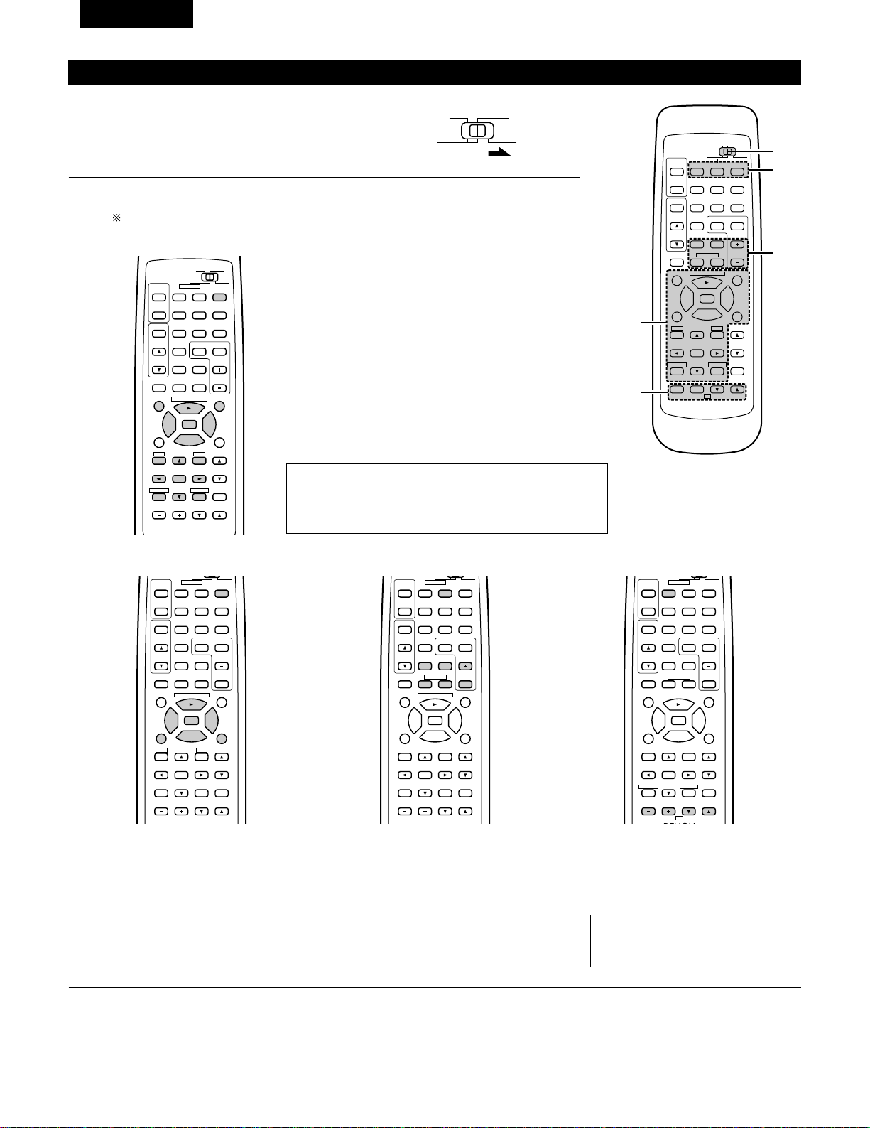
42
FRANCAIS
2
Actionner le composant vidéo.
• Pour les détails, se reporter aux instructions d’utilisation du composant.
Certains modèles ne peuvent pas être actionnés avec cette unité de télécommande.
98
DISPLAY
MUTING
VOLUME
TITLE
DISC SKIP+
CD·MD/CDR·DVD/VDP
SET UP
SELECT
MENU
ON
OFF
RECEIVER
DVD/VDP
TV VCR
0
0
2
2
3
AUDIO
CD
MD/CDR
VIDEO
POWER
6
7
6
7
VIDEO SELECT
SP-A SP-B
STATUS
RETURN
a. Pour lecteur DVD
POWER : Mise sous/hors tension
2 : Arrêt
1 : Lecture
8,9 : Recherche automatique (repérage)
3 : Pause
TITLE : Appeler le titre
MENU : Appeler le menu
DISPLAY : Changer l’affichage
SET UP : Installation de DVD
RETURN : Retour de menu
• , ª : Curseur vers le haut/bas
0 , 1 : Curseur vers la gauche/droite
SELECT : Entrer le réglage
DISC SKIP
+
:Sélection du disque
REMARQUE:
Certains fabricants utilisent des noms différents pour les
touches de commande de DVD, donc se reporter également
aux instructions de télécommande de ce composant.
b. Pour lecteur de vidéodisque (VDP) c. Pour platine vidéo (VCR) d. Pour téléviseur
98
VOLUME
TITLE
DISC SKIP+
CD·MD/CDR·DVD/VDP
SET UP
MENU
ON
OFF
RECEIVER
DVD/VDP
TV VCR
0
0
2
2
3
AUDIO
VIDEO
POWER
6
7
6
7
SP-A SP-B
98
CD DVD/VDP
VCR
V.AUX
TUNER
SHIFT
DISC SKIP+
MULTI
MULTI
VOL.
TAPE
MONITOR
CD·MD/CDR·DVD/VDP
CHANNEL
ON
OFF
RECEIVER
DVD/VDP
TV VCR
PHONO
0
0
2
2
3
AUDIO
VIDEO
POWER
DECK
·
VCR
6
7
6
7
98
B
CD DVD/VDP
VOLUME
CHANNEL
DISPLAY
MUTING
TV
SELECT
CHANNEL
ON
OFF
RECEIVER
DVD/VDP
TV VCR
PHONO
0
0
2
2
3
AUDIO
VIDEO
POWER
DECK
·
VCR
6
7
6
7
VIDEO SELECT
STATUS
RETURN
POWER : Mise sous/hors tension
6,7 : Recherche manuelle
(en arrière et en avant)
2 : Arrêt
1 : Lecture
8,9 : Recherche automatique
(repérage)
3 : Pause
POWER : Mise sous/hors tension
6,7 : Recherche manuelle
(en arrière et en avant)
2 : Arrêt
1 : Lecture
CHANNEL : Changer le canal
+,–
POWER : Mise sous/hors tension
VOLUME : Augmentation/baisse
• , ª de volume
CHANNEL : Changer le canal
+,–
Utilisation d’un composant vidéo sauvegardé dans la mémoire préréglée
1
Placer le commutateur coulissant sur la position
“VIDEO”.
98
B
CD DVD/VDP
VCR
V.AUX
TUNER
SHIFT
REMOTE CONTROL UNIT RC-872
VOLUME
CHANNEL
DISPLAY
MUTING
VOLUME
TITLE
DISC SKIP+
MULTI
MULTI
VOL.
TAPE
MONITOR
CD·MD/CDR·DVD/VDP
TV
SET UP
SELECT
MENU
CHANNEL
ON
OFF
RECEIVER
DVD/VDP
TV VCR
PHONO
0
0
2
2
3
AUDIO
CD
MD/CD-R
VIDEO
POWER
DECK
·
VCR
6
7
6
7
VIDEO SELECT
SP-A SP-B
STATUS
RETURN
2-c
1
2
2-a,b
2-d
AUDIO
CD
MD/CD-R
VIDEO
REMARQUE:
La télévision peut être utilisée quelle
que soit la position du commutateur.
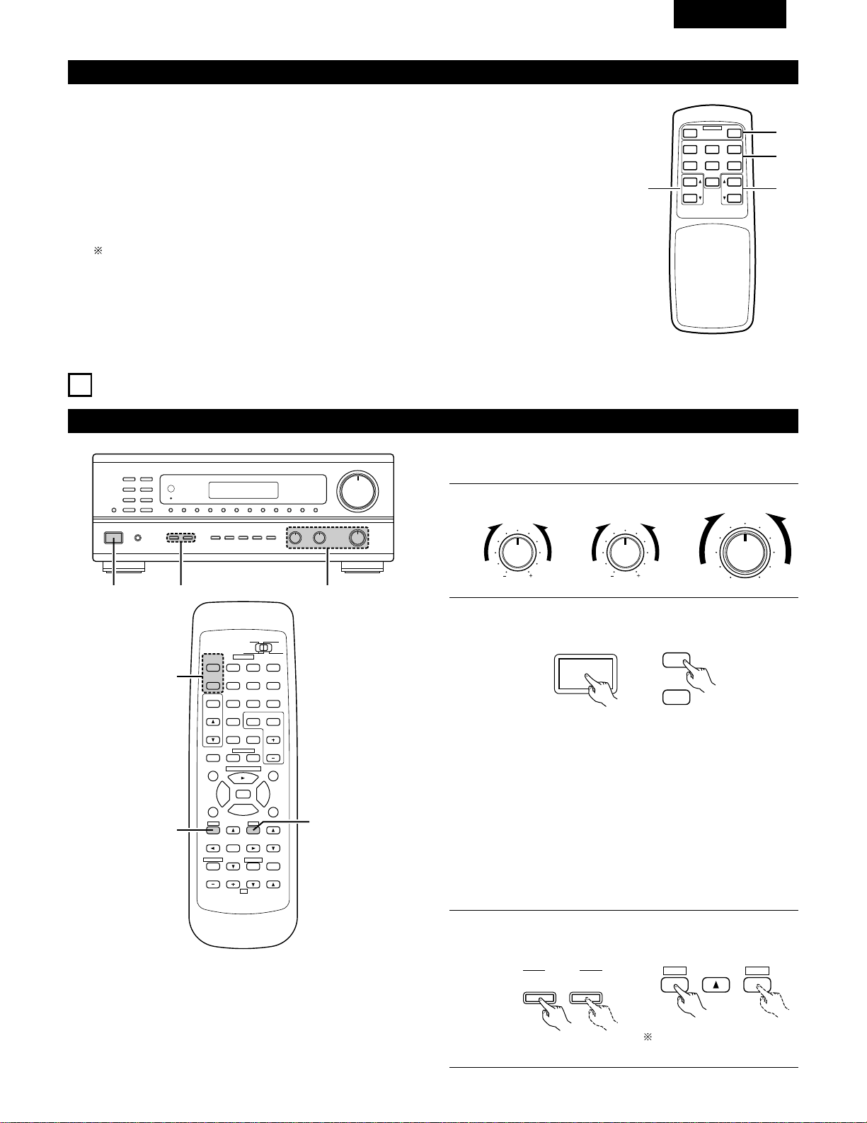
43
FRANCAIS
Télécommande multi-source (RC-873)
Cette télécommande est une télécommande pour la lecture multi-source ou multi-zone.
Les touches w ne peuvent pas être utilisées lorsque le mode multi-source de l’unité principale est réglé en
mode REC OUT (sortie d’enregistrement).
Les touches r peuvent être utilisées seulement lorsque le mode multi-source de l’unité principale est réglé
en mode MULTI.
q Touches d’alimentation ON/OFF (POWER) de l’appareil principal.
w Touches de commande de fonction de sortie de la borne MULTI SOURCE (PHONO, TUNER, CD,
DVD/VDP, VCR, V.AUX et TAPE (cassette).
e Touches de commande de niveau de sortie de la borne MULTI SOURCE (augmentation et diminution
de VOLUME).
REGLAGE PAR DEFAUT (MULTI VOLUME LEVEL) : - - - dB (MINIMUM)
r Touches PRESET (préréglage Haut et Bas) (lorsque la fonction MULTI SOURCE est réglée sur TUNER).
8
OPERATIONS
Avant l’utilisation
Préparatifs:
Vérifier que toutes les connexions sont bonnes.
1
Régler à la position centrale.
BASS TREBLE BALANCE
LR
2
Allumer l’alimentation.
Appuyer l’interrupteur de mise en marche (touche).
ON / STANDBY
• ON/STANDBY
Lorsqu’on appuie sur la touche, l’alimentation s’allume et
l’affichage s’éclaire.
Lorsqu’on appuie encore, l’alimentation s’éteint, le mode de
veille est mis et l’affichage s’éteint.
Plusieurs secondes sont nécessaires à partir du moment où
l’interrupteur d’alimentation est réglé sur la position “ON”
avant que le son soit émis. Ceci est dû au circuit de mise en
sourdine qui évite le bruit lors de la mise sous et hors
tension.
Régler l’interrupteur POWER sur cette position pour mettre
l’appareil sous et hors tension à l’aide de la télécommende
fournie (RC-872).
1
B
23
98
B
CD DVD/VDP
VCR
V.AUX
TUNER
SHIFT
REMOTE CONTROL UNIT RC-872
VOLUME
CHANNEL
DISPLAY
MUTING
VOLUME
TITLE
DISC SKIP+
MULTI
MULTI
VOL.
TAPE
MONITOR
CD·MD/CDR·DVD/VDP
TV
SET UP
SELECT
MENU
CHANNEL
ON
OFF
RECEIVER
DVD/VDP
TV VCR
PHONO
0
0
2
2
3
AUDIO
CD
MD/CD-R
VIDEO
POWER
DECK
·
VCR
6
7
6
7
VIDEO SELECT
SP-A SP-B
STATUS
RETURN
3
3
2
3
Sélectionner les enceintes avant.
Appuyer sur le commutateur d‘enceinte A ou B pour activer
l’enceinte.
A
B
SPEAKER
ON
OFF
RECEIVER
SET UP
MENU
SP-A SP-B
B
MULTI SOURCE REMOTE CONTROL UNIT
RC-873
POWER
PHONO CD
DVD/VDP
OFF
ON
VCR V.AUX
TUNER
PRESET VOLUME
TAPE
MONITOR
q
w
er
Régler le commutateur
coulissant vers “AUDIO”.
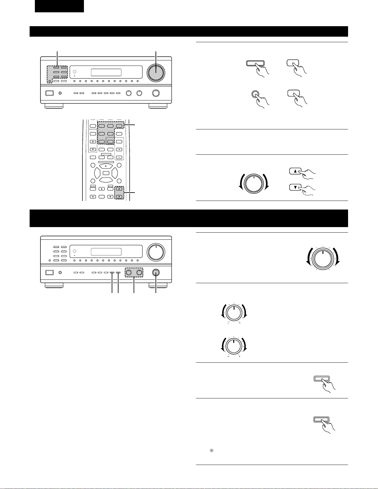
44
FRANCAIS
Lecture de la source de programme
B
13
1
Appuyer sur la touche de la source de programme à reproduire.
EX 1: CD
EX 2: TAPE
• Appuyer une nouvelle fois sur la touche pour changer la source
à l’entrée TAPE MONITOR, à nouveau pour annuler l’entrée.
2
Commencer la lecture sur le composant sélectionné.
Pour les instructions d’utilisation, se reporter aux manuels des
divers composants.
3
Ajuster la commande VOLUME.
CD
CD
TAPE
MONITOR
TAPE
MONITOR
VOLUME
VOLUME
Réglage de la commande BALANCE TONE (tonalité d’équilibre) et LOUDNESS
(compensation physiologique)
1
B
243
1
Régler la commande BALANCE (équilibre)
avant gauche/droite.
Tourner la commande dans le sens
inverse des aiguilles d’une montre pour
réduire le volume du canal droit, dans le
sens des aiguilles d’une montre pour
augmenter le volume du canal gauche.
BALANCE
LR
2
Ajuster le commande BASS (graves) et le TREBLE (aiguës).
BASS
TREBLE
Tourner la commande dans le sens des
aiguilles d’une montre pour augmenter
les graves, dans le sens inverse des
aiguilles d’une montre pour les réduire.
Tourner la commande dans le sens des
aiguilles d’une montre pour augmenter
les aiguës, dans le sens inverse des
aiguilles d’une montre pour les réduire.
3
Appuyer sur la touche TONE DEFEAT
(désactivation).
Utiliser cette touche lorsque vous ne
voulez pas régler le son.
TONE
DEFEAT
4
Appuyer sur la touche LOUDNESS
(compensation physiologique).
Appuyer sur le touche de compensation
physiologique lors de l’écoute de la
musique à un niveau de volume bas. Les
notes basses et aiguës sont corrigées
afin de produire un son naturel.
Le touche LOUDNESS (compensation physiologique) peut
être utilisé quand le mode TONE DEFEAT ON.
LOUDNESS
98
CD DVD/VDP
VCR
V.AUX
TUNER
SHIFT
VOLUME
TITLE
DISC SKIP+
MULTI
MULTI
VOL.
TAPE
MONITOR
CD·MD/CDR·DVD/VDP
SET UP
SELECT
MENU
CHANNEL
OFF
PHONO
0
0
2
2
3
DECK
·
VCR
6
7
6
7
SP-A SP-B
3
1
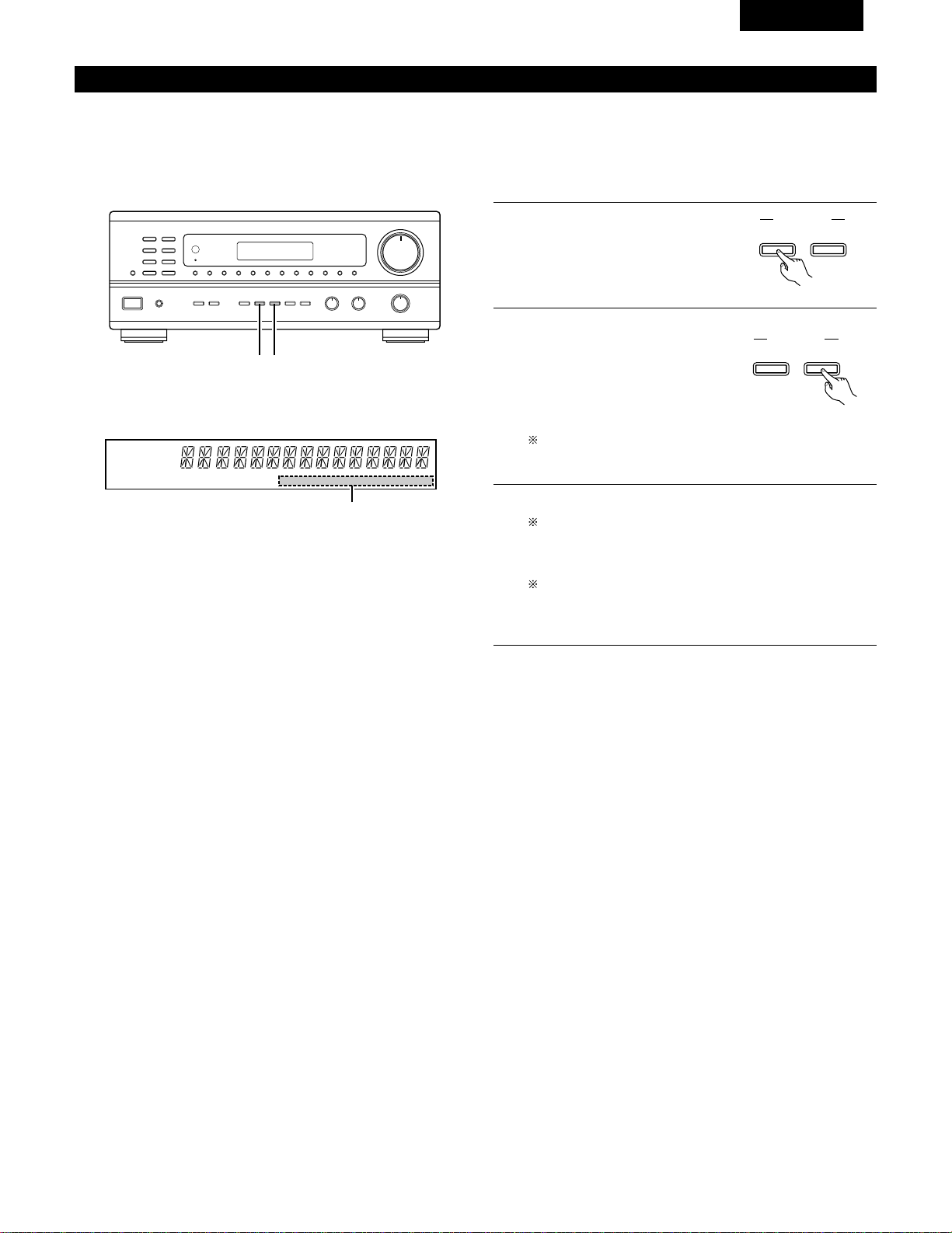
45
FRANCAIS
Enregistrement/lecture de source multiple
La fonction de source multiple vous permet d’enregistrer une source autre que la source actuellement reproduite ou de sortir son signal vers la
borne de sortie de source multiple.
2
Enregistrement d’une source autre que celle en cours de lecture
(mode REC OUT (sortie d’enregistrement))
B
1 2
1
Appuyer sur la touche MULTI
SOURCE MODE jusqu’à ce que “REC
OUT” (sortie d’enregistrement)
apparaisse sur l'affichage.
MULTI SOURCE
MODE
SELECT
2
Sélectionner la source à envoyer à
la borne de sortie d’enregistrement.
Appuyer répétitivement sur la
touche MULTI SOURCE SELECT
(sélectionner multi-source) jusqu’à
ce que la source désirée apparaisse
sur l’affichage.
Le mode REC OUT (sortie d’enregistrement) ne peut pas
être réglé à partir de la télécommande.
3
La source sélectionnée est indiquée.
Les signaux de la source sélectionnée avec le mode REC
OUT (sortie d’enregistrement) sont également envoyées à
partir des bornes MULTI SOURCE AUDIO/VIDEO OUT
(sortie audio/vidéo multi-source).
Pour annuler le mode REC OUT.
Appuyer sur la touche MULTI SOURCE MODE jusqu’à ce
que “SOURCE” apparaisse sur l’affichage.
MULTI SOURCE
MODE
SELECT
AUTO RDS CH
STEREO TUNED
DISPLAY
MULTI TONE SP-A SP-B PHONO CD TUNER VDP VCR V.AUX TAPE
3
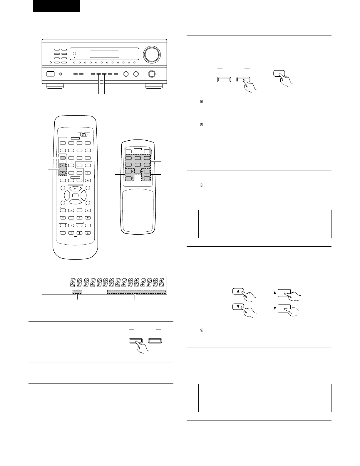
46
FRANCAIS
2
Lecture d’une source autre que celle en cours de lecture dans une autre pièce (MULTI) mode
B
1 3
98
B
CD DVD/VDP
VCR
V.AUX
TUNER
SHIFT
REMOTE CONTROL UNIT RC-872
VOLUME
CHANNEL
DISPLAY
MUTING
MASTER
VOL.
TITLE
DISC SKIP+
MULTI
MULTI
VOL.
TAPE
MONITOR
CD·MD/CDR·DVD/VDP
TV
SET UP
SELECT
MENU
CHANNEL
ON
OFF
RECEIVER
DVD/VDP
TV VCR
PHONO
0
0
2
2
3
AUDIO
CD
MD/CD-R
VIDEO
POWER
DECK
·
VCR
6
7
6
7
VIDEO SELECT
SP-A SP-B
STATUS
RETURN
5
3
AUTO RDS CH
STEREO TUNED
DISPLAY
MULTI TONE SP-A SP-B PHONO CD TUNER VDP VCR V.AUX TAPE
42
RC-872
RC-873
B
MULTI SOURCE REMOTE CONTROL UNIT
RC-873
POWER
PHONO CD
DVD/VDP
OFF
ON
VCR V.AUX
TUNER
PRESET VOLUME
TAPE
MONITOR
3
56
3
Sélectionner la source à envoyer à la borne de sortie MULTI
SOURCE. Appuyer répétitivement sur la touche MULTI
SOURCE SELECT (sélectionner multi-source), jusqu’à ce que la
source désirée apparaisse sur l’affichage.
4
La source sélectionnée est indiquée.
Pour annuler le mode MULTI.
Appuyer sur la touche MULTI SOURCE MODE ou appuyer
répétitivement sur la touche MULTI de la télécommande
RC-872 jusqu’à ce que “SOURCE” apparaisse sur l’affichage.
REMARQUE:
Les signaux de la source sélectionnée en mode MULTI sont
également envoyés des bornes de sortie d’enregistrement
TAPE (cassette) et VCR (magnétoscope).
5
Le niveau de sortie des bornes MULTI SOURCE AUDIO peut
être contrôlé à l’aide des touches MULTI VOLUME • et ª
(augmentation ou diminution multi-volume) de la
télécommande RC-872 ou sur les touches VOLUME UP et
DOWN (augmentation ou diminution multi-volume) de la
télécommande source RC-873.
6
Lorsque MULTI SOURCE (multi-source) fonction est réglée sur
TUNER, le canal préréglé peut être sélectionné à l’aide des
touches PRESET (préréglage) Haut et Bas de la télécommande
multi-source RC-873. (Ceci est seulement possible lorsque
l’unité principale est en mode MULTI.)
REMARQUE:
Il est à noter que cette touche commute également le canal
de réception préréglé sur l’unité principale lors de la lecture
ou de l’enregistrement du tuner en mode MULTI.
Lorsque la touche MULTI de la télécommande est
enfoncée, le mode MULTI est réglé directement (l’indicateur
“MULTI” s’allume), et la source à envoyer à partir des
bornes MULTI SOURCE peut être sélectionnée.
Lorsque les touches PHONO — TAPE (cassette) de la
télécommande multi-source RC-873 est enfoncée, le mode
MULTI est réglé directement (l’indicateur “MULTI”
s’allume), et la source à envoyer à partir des bornes MULTI
SOURCE peut être sélectionnée directement. (Ce mode ne
peut pas être sélectionné lorsque l’unité principale est en
mode de REC OUT.)
MULTI SOURCE
MODE
SELECT
MULTI
(RC-872)
MULTI
VOL.
VOLUME
(RC-872) (RC-873)
REGLAGE PAR DEFAUT (MULTI VOLUME LEVEL) :
- - - dB (MINIMUM)
1
Appuyer répétitivement sur la
touche MULTI SOURCE jusqu’à ce
que “MULTI OUT” (sortie multi-
source) apparaisse sur l’affichage.
MULTI SOURCE
MODE
SELECT
2
Activer l’indicateur “MULTI”.
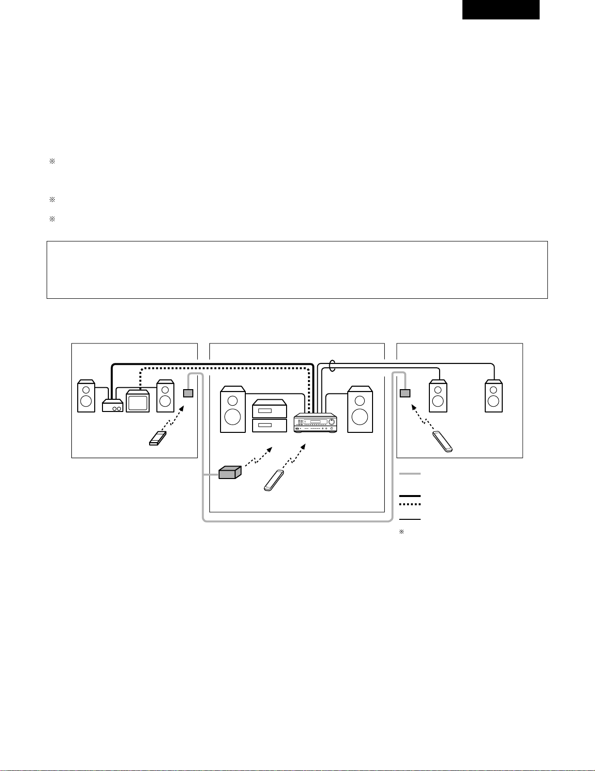
47
FRANCAIS
2
Lecture multi-source et multi-zone
SYSTEME DE DIVERTISSEMENT MUSICAL MULTI-PIECE
• Lorsque les sorties des bornes MULTI SOURCE AUDIO/VIDEO OUT sont câblées et raccordées sur des amplificateurs de puissance ou des
écrans de télévision installés dans d’autres pièces, des sources différents peuvent être lues dans des pièces différentes de la principale, là où
cet appareil et les autres périphériques de lecture sont installés. (Se référer au schéma SUB ROOM-1 (pièce secondaire 1.)
• Lorsque la sortie des bornes SPEAKER SYSTEM-B est câblée et connectée à des enceintes dans une autre pièce, la même source peut être
lue dans la pièce principale et dans une pièce secondaire. Réglez le sélecteur des enceintes SPEAKER A/B de cet appareil en fonction de la
pièce dans laquelle la source doit être diffusée. (Se référer au schéma SUB ROOM-2 (pièce secondaire 2.)
• Lorsqu’une télécommande de pièce à pièce vendue séparément (DENON RC-616 ou 617) est câblée et connectée entre la pièce principale et
la pièce secondaire, les appareils télécommandables dans la pièce principale peuvent être commandés depuis la pièce secondaire à l’aide de la
télécommande.
Pendant une lecture multi-source en SUB-ROOM 1, la sortie MULTI SOURCE de cet appareil peut être contrôlée par la télécommande multi
source RC-873 fournie.
Les opérations sur la télécommande RC-873 autres que l’augmentation et la diminution de volume de la sortie multi-source ne peuvent pas
être effectuées lorsque l’unité principale est en mode REC OUT (sortie d’enregistrement).
Pendant une lecture multi-source en SUB-ROOM 2, la sortie des lecteurs CD DENON ou des platines cassettes etc. de cet appareil peut être
contrôlée par la télécommane du système RC-872.
Pour commander les appareils de lecture autres que ceux mentionnés ci-dessus, utiliser la télécommande de l’appareil ou prérégler une
télécommande programmable, vendue séparément (DENON RC-770, etc.).
REMARQUES:
• Utiliser un cordon à fiche à broche coaxial de 75 Ω / ohms pour les signaux vidéo pour connecter et câbler la sortie MULTI SOURCE VIDEO.
Pour la sortie AUDIO, utiliser des cordons à fiche à broche de haute qualité d’une telle manière qu’il n’y ait pas de ronflement ou de bruit.
• Pour les instructions sur l’installation et le fonctionnement des appareils vendus séparément, se référer aux modes d’emploi des appareils
respectifs.
PIECE-1 PIECE PRINCIPALE
PIECE-2
AMPLIFICATEUR
TV
RC-617
DRA-685
RC-616
RC-617
SYSTEME D’ENCEINTE-B
B
Ligne de commande de SYSTEME DE
TELECOMMANDE DE PIECE A PIECE
(vendu séparément)
Câble de signal MULTI SOURCE AUDIO
Câble d’ENCEINTE
Se référer à CONNEXIONS dans les pages 32
et 33.
Câble de signal MULTI SOURCE VIDEO
(75
º / ohms)
9
8
B
0
0
2
2
3
6
7
6
7
B
SYSTEME DE DIVERTISSEMENT MUSICAL MULTI-PIECE
TELECOMMANDE MULTI-
SOURCE RC-873
(ou TELECOMMANDE
PROGRAMMABLE RC-770)
TELECOMMANDE DE
SYSTEME RC-872
RC-872
(ou TELECOMMANDE
PROGRAMMABLE RC-770)
• Accessoires
•
TELECOMMANDE DE SYSTEME
RC-872
•
TELECOMMANDE MULTI-SOURCE
RC-873
• Vendu séparément
•
EMETTEUR IR RC-616
•
DETECTEUR RC-617
•
TELECOMMANDE PROGRAMMABLE
RC-770
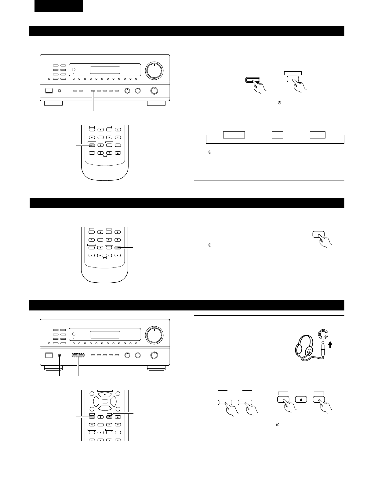
48
FRANCAIS
Lecture simultanée
1
Maintenez enfoncé le touche VIDEO SELECT jusqu’à ce que la
source désirée apparaisse sur l’écran.
La source vidéo change de la manière suivante chaque fois que
la touche est enfoncée.
Annulation de la lecture simultanée.
• Appuyer à nouveau sur la touche VIDEO SELECT.
• Changer la source de programme au composant connecté à
la vidéo.
Utiliser cette touche pour contrôler une source vidéo autre que la source audio.
111
B
1
DVD/VDP VCR V.AUX
VIDEO
SELECT
VIDEO SELECT
RETURN
B
REMOTE CONTROL UNIT RC-872
VOLUME
CHANNEL
DISPLAY
MUTING
MASTER
VOL.
TV
SET UP
SELECT
MENU
VIDEO SELECT
SP-A SP-B
STATUS
RETURN
1
Utilisation de la fonction de mise en sourdine
Utiliser cette fonction pour désactiver provisoirement la sortie audio.
• Précaution:
La mise hors tension de l’appareil permet d’annuler les réglages.
1
B
REMOTE CONTROL UNIT RC-872
VOLUME
CHANNEL
DISPLAY
MUTING
VOLUME
TV
SET UP
SELECT
MENU
VIDEO SELECT
SP-A SP-B
STATUS
RETURN
1
Appuyer sur la touche MUTING (mise en
sourdine).
Annulation de la mise en sourdine.
Appuyer à nouveau sur la touche
MUTING (mise en sourdine).
MUTING
Ecoute avec casque
1
Connecter le casque à la prise
casque du panneau avant.
PHONES
2
Appuyer sur les touches SPEAKER A ou B pour éteindre les
enceintes.
B
12
A
B
SPEAKER
SET UP
MENU
SP-A SP-B
98
DISPLAY
MUTING
VOLUME
TITLE
DISC SKIP+
CD·MD/CDR·DVD/VDP
SET UP
SELECT
MENU
2
3
6
7
VIDEO SELECT
SP-A SP-B
STATUS
RETURN
2
2
Régler le commutateur
coulissant vers “AUDIO”.
Régler le commutateur
coulissant vers “AUDIO”.
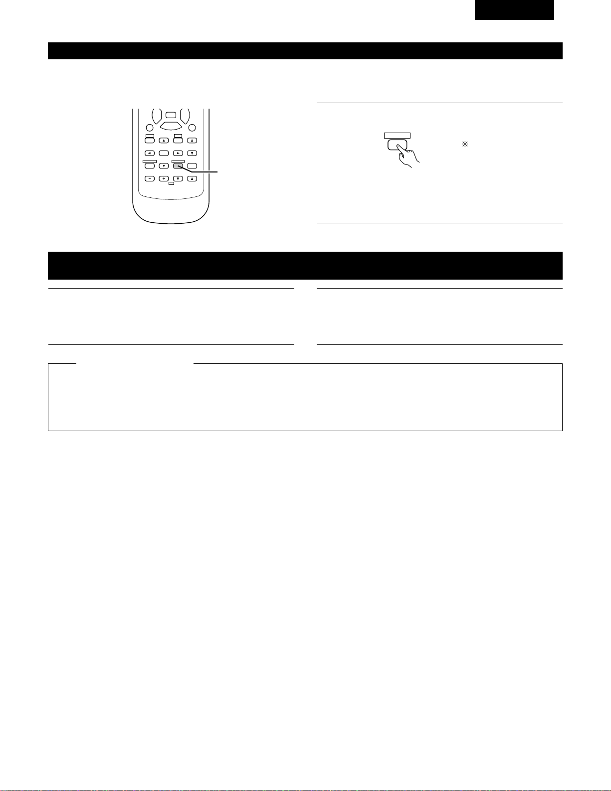
49
FRANCAIS
Affichage du panneau avant
Lorsqu’une commande est éxecutée à partir de la télécommande, cette commande apparaît sur l’affichage, ce qui rend sa vérification possible
visuellement.
L’état de service de l’appareil peut également être vérifié sur l’affichage en utilisant la procédure décrite ci-dessous.
1
Appuyer sur la touche STATUS.
DISPLAY
STATUS
• Les sources d’entrée et de sortie et le réglage d’ambiance,
etc. apparaissent dans l’ordre sur l’affichage chaque fois que
la touche est enfoncée.
98
B
REMOTE CONTROL UNIT RC-872
VOLUME
CHANNEL
DISPLAY
MUTING
VOLUME
TITLE
TV
SET UP
SELECT
MENU
2
3
6
7
VIDEO SELECT
SP-A SP-B
STATUS
RETURN
1
1
Suivre les étapes 1 à 3 sous “Lecture d’un programme source”.
Enregistrement d’un programme source
(enregistrement de la source avec contrôle simultané)
2
Démarrer l’enregistrement sur la platine à cassettes ou le
magnétoscope.
Pour les instructions, se rapporter aux instructions d’utilisation
de l’appareil.
Les signaux de la source sélectionnée avec la touche de sélection de fonction sont transmis simultanément aux prises TAPE et VCR REC
OUT. Si un total de deux platines à cassettes/magnétoscopes sont connectés et réglés en mode d’enregistrement, la même source peut
être enregistrée simultanément sur chaque platine/magnétoscope.
De plus, si la touche TAPE MONITOR est enfoncée, les signaux audio de la platine à cassette sont transmis aux prises VCR AUDIO REC
OUT.
Enregistrement simultané
2
Fonction de contrôle de bande
Lorsqu’une platine à cassettes à trois têtes est utilisée, le son résultant de l’enregistrement en cours peut être contrôlé pendant
l’enregistrement en appuyant sur la touche TAPE MONITOR.
Appuyer à nouveau sur la touche pour annuler le contrôle.
Régler le commutateur
coulissant vers “AUDIO”.
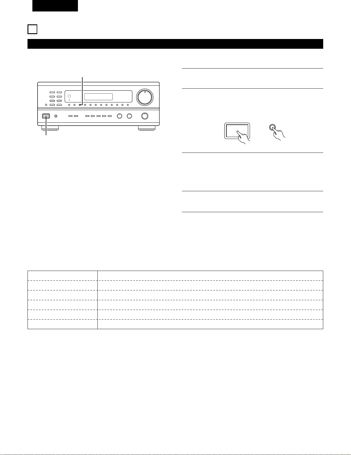
50
FRANCAIS
ECOUTER DE LA RADIO
Mémoire préréglée automatique
REMARQUES:
• Si une station FM ne peut pas être automatiquement préréglée à
cause d’une mauvaise réception, utiliser l’opération de
“Syntonisation manuelle” pour syntoniser la station, puis la
prérégler en utilisant l’opération de “Mémoire préréglée”
manuelle.
• Pour interrompre cette fonction, appuyer le touche d’alimentation.
2
3
Cet appareil est équipé d’une fonction de recherche automatique d’émissions de radiodiffusion en FM et de leur stockage dans la mémoire
préréglée.
Allumer l’appareil en utilisant l’interrupteur de mise en marche
tout en maintenant enfoncé le touche MEMORY.
L’appareil commence automatiquement la recherche de
stations de radiodiffusion en FM.
Lorsque la première station de radiodiffusion en FM est
trouvée, cette station est stockée dans la mémoire préréglée
au canal A1. Les stations suivantes sont automatiquement
stockées dans l’ordre aux canaux préréglés A2 à A8, B1 à B8,
C1 à C8, D1 à D8 et E1 à E8 pour un maximum de 40 stations.
4
Le canal A1 est syntonisé après la fin de l’opération de
mémoire préréglée automatique.
9
B
2
2
AUTO TUNER PRESETS
A1 ~ A8 87,5/89,1/98,1/107,9/90,1/90,1/90,1/90,1 MHz
B1 ~ B8 520/600/1000/1400/1500/1710 kHz/90,1/90,1 MHz
C1 ~ C8 90,1 MHz
D1 ~ D8 90,1 MHz
E1 ~ E8 90,1 MHz
2
VALEUR PAR DEFAUT
ON / STANDBY
MEMORY
1
Eteignez l’appareil.
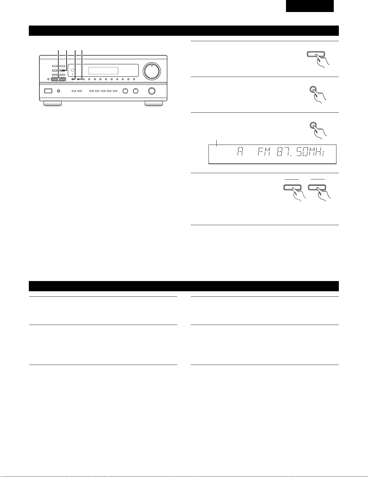
51
FRANCAIS
Syntonisation automatique
1
Régler la fonction d’entrée à “TUNER”.
2
En regardant l’affichage, appuyer sur la
touche BAND (bande) pour sélectionner la
bande désirée (AM ou FM).
BAND
3
Appuyer sur la touche MODE (mode) pour
régler le mode de syntonisation automatique.
AUTO CH
TUNED
TUNER
4
Appuyer sur la touche TUNING UP
(augmentation de syntonisation)
ou TUNING DOWN (diminution
de syntonisation).
TUNING
UPDOWN
Allumé
• La recherche automatique commence, puis s’arrête lorsqu’une
station est syntonisée.
REMARQUE:
• Tout en étant en mode de syntonisation automatique sur la bande
FM, le témoin “STEREO” s’allume sur l’affichage lorsqu’une émission
stéréo est syntonisée.
Aux fréquences ouvertes, le bruit est mis en sourdine et les témoins
“TUNED” et “STEREO” s’éteignent.
B
1423
Syntonisation manuelle
1
Régler la fonction d’entrée à “TUNER”.
2
En regardant l’affichage, appuyer sur la touche BAND (bande)
pour sélectionner la bande désirée (AM ou FM).
3
Appuyer sur la touche MODE (mode) pour régler le mode de
syntonisation manuelle. Vérifier que le témoin “AUTO” de
l’affichage s’éteint.
4
Appuyer sur la touche TUNING UP (augmentation de
syntonisation) ou TUNING DOWN (diminution de syntonisation)
pour syntoniser la station désirée.
La fréquence change continuellement lorsque la touche est
maintenue enfoncée.
REMARQUE:
• Lorsque le mode de syntonisation manuelle est réglé, les émissions en stéréo FM sont reçues en mode monaural et le témoin “STEREO”
s’éteint.
TUNER
MODE
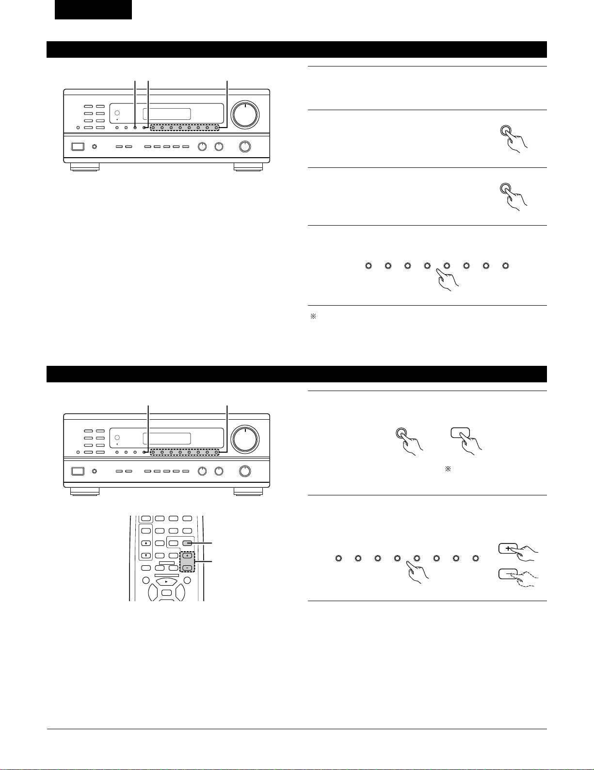
52
FRANCAIS
Mémoire préréglée
2
Appuyer sur la touche MEMORY (mémoire).
MEMORY
3
Appuyer sur la touche SHIFT et
sélectionner le bloc de mémoire désiré (A
à E).
4
Appuyer sur la touche canal préréglé (1 à 8) pour sélectionner le
canal préréglé désiré (1 à 8).
Pour prérégler d’autres canaux, répéter les étapes 1 à 4.
Un total de 40 stations de radiodiffusion peut être préréglées — 8
stations (canaux 1 à 8) dans chacun des blocs A à E.
B
23 4
1
Utiliser l’opération de “Syntonisation automatique” ou de
“Syntonisation manuelle” pour syntoniser la station à prérégler
dans la mémoire.
SHIFT
12345678
Rappel de stations préréglées
1
En regardant l’affichage, appuyer sur la touche SHIFT pour
sélectionner le bloc de mémoire préréglé.
2
Tout en regardant l’affichage, appuyer sur la touche canal
préréglé (1 à 8) pour sélectionner le canal préréglé désiré. (Lors
de l’utilisation de la télécommande, sélectionner le canal
préréglé en appuyant sur la touche préréglage Haut ou Bas.
B
1 2
SHIFT
SHIFT
12345678
CHANNEL
98
VCR
V.AUX
TUNER
SHIFT
TITLE
DISC SKIP+
MULTI
MULTI
VOL.
TAPE
MONITOR
CD·MD/CDR·DVD/VDP
CHANNEL
OFF
0
0
2
3
DECK
·
VCR
6
7
1
2
Régler le commutateur
coulissant vers “AUDIO”.
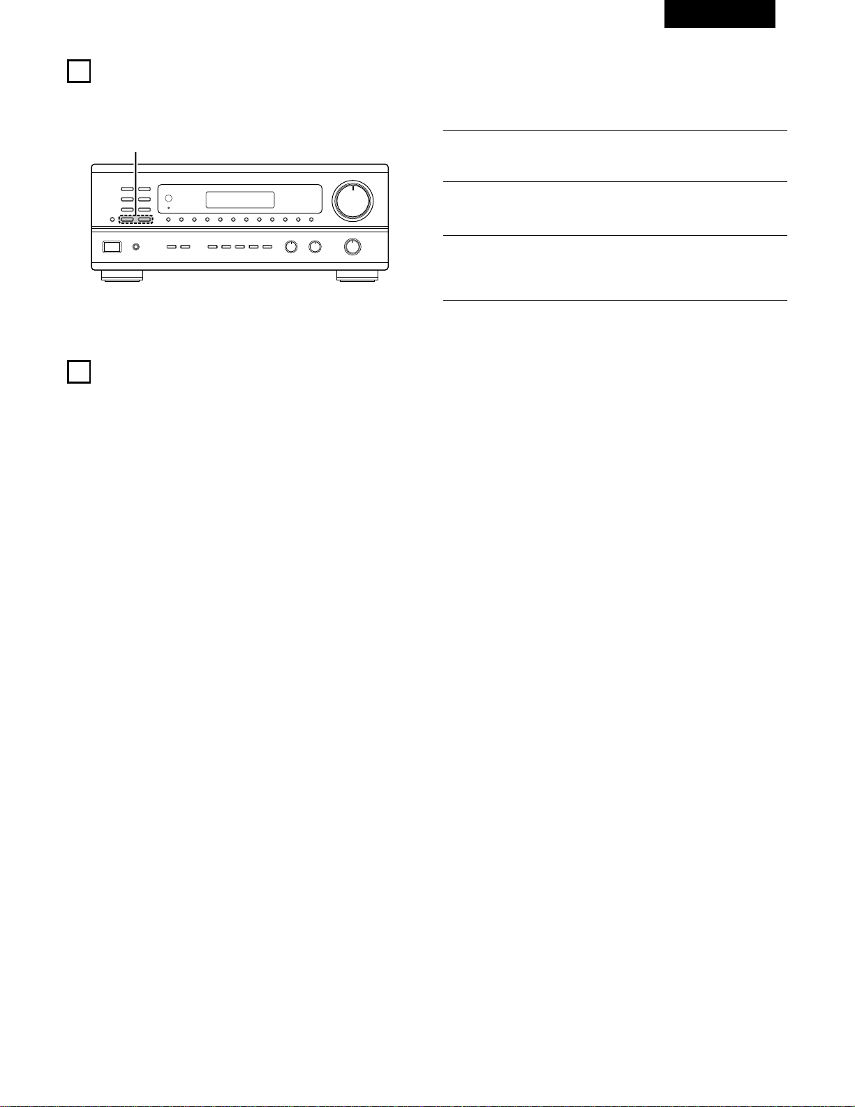
53
FRANCAIS
10
INITIALISATION DU MICROPROCESSEUR
Lorsque l’indication de l’affichage est anormale ou quand l’utilisation de l’appareil ne donne pas les résultats escomptés, le microprocesseur doit
être initialisé en suivant la procédure suivante.
B
2
1
Eteindre l’appareil et retirer le cordon CA de la prise murale.
2
Maintenir le touche TUNING UP suivant et le touche TUNING
DOWN, et brancher le cordon CA dans la prise.
3
Vérifier que l’affichage clignote dans son intégralité à un
intervalle de 1 seconde environ, relâcher les doigts des 2
touches, et le microprocesseur sera initialisé.
11
MEMOIRE DE DERNIERE FONCTION
• Cet appareil est équipé d’une mémoire de dernière fonction qui stocke les conditions des réglages d’entrée et de sortie telles qu’elles étaient
immédiatement après la mise hors tension.
• L’appareil est également équipé d’une mémoire de sauvegarde. Cette fonction fournit approximativement une semaine de stockage de
mémoire lorsque l’unité principale est mise hors tension et avec le cordon d’alimentation débranché.
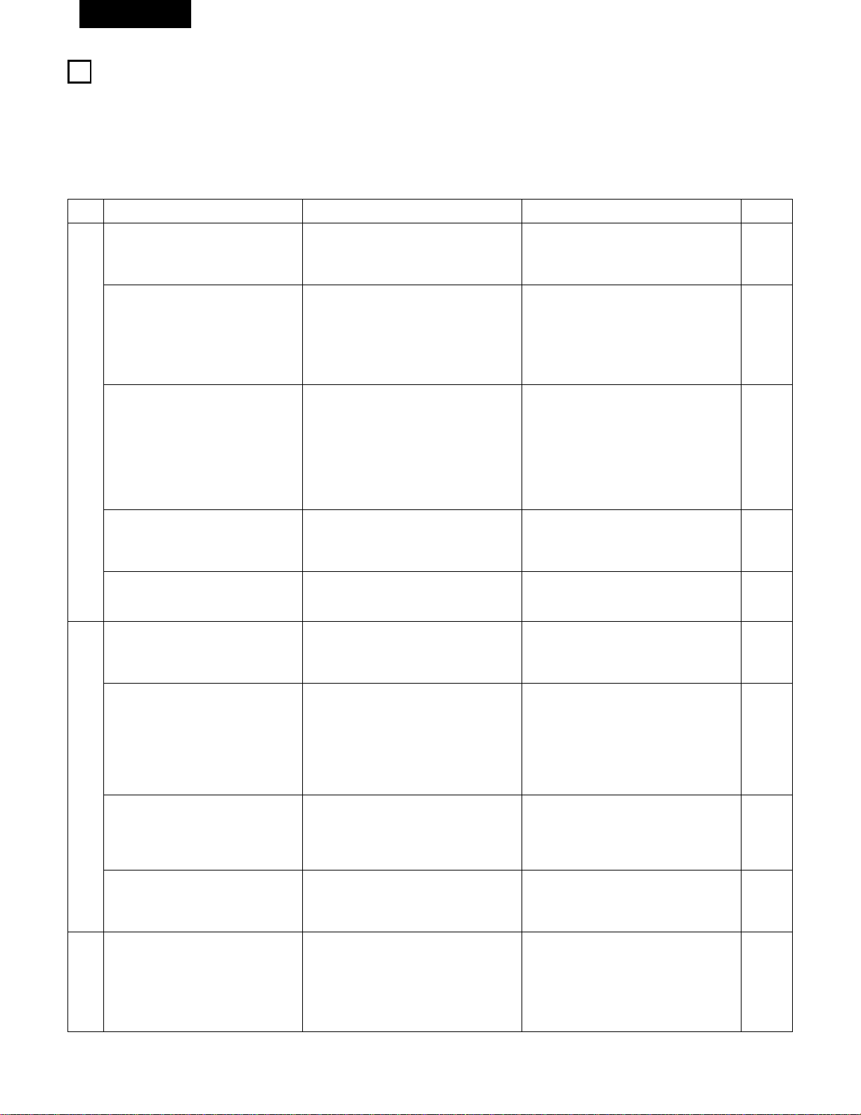
54
FRANCAIS
1
2
DEPISTAGE DES PANNES
Si un problème se produit, vérifier d’abord les points suivants:
1. Les connexions sont-elles correctes ?
2. L’ampli-tuner a-t-il été utilisé conformément au mode d’emploi ?
3. Les enceintes, la platine tourne-disque et les autres appareils fonctionnent-ils correctement ?
Si cet appareil ne fonctionne pas correctement, vérifier les points énumérés dans le tableau ci-dessous. Si le problème persiste, il peut y avoir un
mauvais fonctionnement. Débrancher immédiatement le cordon d’alimentation et contacter le revendeur.
Symptôme
Affichage pas allumé et aucun son n’est
produit lorsque l’appareil est allumé.
Affichage allumé mais aucun son n‘est
produit.
L
’affichage
—
PROTECT
—
apparaît.
Cause Remèdes
• Le cordon d’alimentation n’est pas bien
branché.
• Les cordons des enceintes ne sont pas
correctement branchés.
• Mauvaise position de la touche de fonction
audio.
• Commande de volume réglée au minimum.
• La sourdine (MUTING) est activée.
• Les bornes d’enceinte sont court-
circuitées.
• Les trous de ventilation de l’appareil sont
obstrués.
• L’appareil fonctionne en continu à haute
puissance et/ou la ventilation n’est pas
appropriée.
• Vérifier l’insertion de la fiche du cordon
d’alimentation.
• Mettre sous tension avec la télécommande
après avoir enclenché la touche d’alimentation.
• Brancher correctement.
• Régler sur une position appropriée.
• Augmenter le volume jusqu’à un niveau
approprié.
• Désenclencher la sourdine (MUTING).
• Mettre l’appareil hors tension, connecter
correctement les enceintes, puis le
remettre sous tension.
• Eteindre l’appareil, puis bien l’aérer pour le
refroidir.
Dès que l’appareil est refroidi, le rallumer.
• Eteindre l’appareil, puis bien l’aérer pour le
refroidir.
Dès que l’appareil est refroidi, le rallumer.
Le son n’est produit que par un canal.
• Connexion incomplète des cordons
d’enceinte.
• Connexion incomplète des cordons
d’entrée/sortie.
• Bien connecter.
• Bien connecter.
Page
32
43
35, 36
44
44
48
35, 36
31
31
35, 36
35 ~ 37
Les positions des instruments sont
inversées pendant la lecture en stéréo.
• Inverser les connexions des enceintes
gauche et droite ou des cordons
d’entrée/sortie gauche et droite.
• Vérifier les connexions gauche et droite.
35 ~ 39
Un bourdonnement est produit pendant
la lecture d’un disque.
• Le fil de masse de la platine tourne-disque
n’est pas correctement connecté.
• Connexion de la prise PHONO incomplète.
• Antenne radio ou TV proche.
• Bien connecter.
• Bien connecter.
• Contacter le revendeur.
35
35
–
Un hurlement est produit lorsque le
volume est élevé.
•
La platine tourne-disque et les systèmes
d’enceinte sont trop proches les uns des
autres.
• Le sol est instable et vibre facilement.
• Les éloigner le plus possible.
• Utiliser des amortisseurs pour absorber les
vibrations des enceintes transmises par le
sol. Si la platine tourne-disque n’est pas
équipée d’isolants, utiliser des isolants
audio (disponibles dans le commerce).
–
–
Le son est déformé.
• La pression de la pointe de lecture est trop
faible.
• Poussière ou saleté sur la pointe de
lecture.
• Cellule défectécommande est utilisée.
• Appliquer une pression de pointe de lecture
appropriée.
• Vérifier la pointe de lecture.
• Remplacer la cellule.
–
–
–
Le volume est faible.
• Une cellule à bobine mobile (MC) est
utilisée.
• La remplacer par une cellule à aimant
mobile (MM) ou utiliser un amplificateur de
tête ou installer un transformateur
survolteur.
35
Cet appareil ne fonctionne pas
correctement lorsque la télécommande
est utilisée.
• Les piles sont usées.
• Télécommande trop loin de cet appareil.
• Obstacle entre cet appareil et la
télécommande.
• Une touche différente est enfoncée.
• Les pôles < et > de la pile sont insérés à
l’envers.
• Remplacer les piles par des piles neuves.
• Rapprocher.
• Retirer l’obstacle.
• Appuyer sur la touche appropriée.
• Insérer correctement les piles.
38
38
38
–
38
Problèmes communs se présentant lors de l’écoute de disques
compacts, disques, cassettes et d’émissions FM, etc.
Lors de la lecture de disques.
Télécommande.

55
FRANCAIS
13
SPECIFICATIONS
• Section audio
(Amplificateur de puissance)
Puissance de sortie nominale: 100 W + 100 W (8 Ω/ohms, 20 Hz ~ 20 kHz avec D.H.T. de 0,05%)
Bornes de sortie: A ou B 4 à 16 Ω/ohms
A+B 8 à 16 Ω/ohms
Analogique (Analog)
Entrée LINE — PRE-OUT
Sensibilité d’entrée/Impédance d’entrée:
200 mV / 47 kΩ/kohms
Réponse en fréquence: 10 Hz à 50 kHz ±1,5 dB
Rapport signal/bruit: 100 dB (IHF-A chargée)
Distorsion harmonique totale: 0,009 % (–3 dB à la sortie nominale,8 Ω/ohms) (1 kHz)
Niveau de sortie nominal: 1,2 V
Entrée PHONO — REC OUT
Sensibilité d’entrée/Impédance d’entrée:
3,0 mV / 47 kΩ/kohms
Réponse en fréquence: ±0,5 dB (20 Hz ~ 20 kHz)
Rapport signal/bruit: 74 dB (IHF-A chargée avec 5 mV en entrée)
Distorsion harmonique totale: 0,03 % (1 kHz, 3 V)
Niveau de sortie nominal/Maximum: 150 mV / 7 V
• Section vidéo
(Prises vidéo standard)
Niveau/impédance d’entrée et de sortie:
1 Vc-c, 75 Ω/ohms
Réponse en fréquence: 5 Hz à 10 MHz +1, –3 dB
• Section tuner
[FM] (Remarque: µV à 75 Ω/ohms, 0 dBf =
1 x 10
–15
W
) [AM]
Gamme de réception: 87,5 MHz à 107,9 MHz 520 kHz à 1710 kHz
Sensibilité utile: 1,4 µV (14,2 dBf) 18µV
Seuil de sensibilité 50 dB: MONO 2,8 µV (20,2 dBf)
STEREO 23 µV (38,5 dBf)
Rapport signal/bruit (IHF-A): MONO 80 dB (IHF-A chargée)
STEREO 75 dB (IHF-A chargée)
Distorsion harmonique totale MONO 0,15 % (1 kHz)
STEREO 0,3 %5 (1 kHz)
• Généralités
Alimentation: CA 120 V, 60 Hz
Consommation: 3,4 A
Dimensions externes maximales: 434 (L) x 171 (H) x 416 (P) mm
Poids: 10,0 kg (22 lbs)
• Télécommande RC-872, RC-873
RC-872
Piles: Type R6P/AA (deux piles)
Dimensions externes: 54 (L) x 172 (H) x 27,2 (P) mm
Poids: 100 g (avec les piles)
RC-873
Piles: Type R03/AAA (deux piles)
Dimensions externes: 47,5 (L) x 127 (H) x 18 (P) mm
Poids: 70 g (avec les piles)
* Aux fins d’amélioration, les spécifications et la conception sont sujettes à modification sans préavis.

Printed in Korea 511 3580 108
14-14, AKASAKA 4-CHOME, MINATO-KU, TOKYO 107-8011, JAPAN
Telephone: (03) 3584-8111
Cable: NIPPON COLUMBIA TOKYO Telex: JAPANOLA J22591