Loading ...
Loading ...
Loading ...
© IMPEX INC. www.impex-fitness.com
9
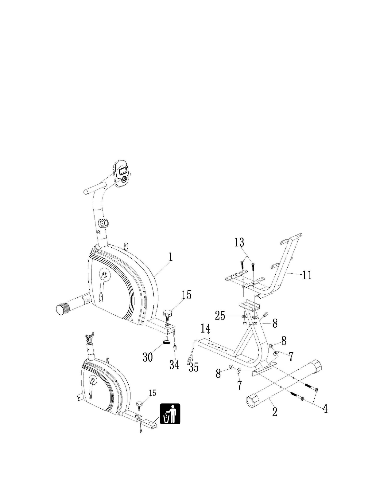
STEP 3
A.) Before starting assembly, pull out the Quick Release Knob (#15), remove and dispose the
Protection Insert.
B.) Connect the Middle Sensor Wire (#34) from Main Frame (#1) to the Middle Sensor Wire (#35)
from the Sliding Frame (#14).
C.) Insert the Sliding Frame (#14) into the Main Frame (#1). Thread the Quick Release Knob (#15)
through selected hole on Main Frame into Sliding Frame to lock it in position. Thread a Leverage
Knob (#30) into the Sliding Frame from bottom. The Leverage Knob needs to touch the floor.
D.) Attach the Rear Stabilizer (#2) to Main Frame. Secure them together with two M8 x 2 3/8”
Carriage Bolts (#4), two Ø 5/8” Curved Washers (#7), and two M8 Acorn Nuts (#8).
E.) Place Seat Support (#11) to Sliding Frame. Secure them together with two M8 x 1 5/8” Carriage
Bolts (#13), two Ø 5/8” Washers (#25), and two M8 Acorn Nuts (#8).
DIAGRAM 3
Loading ...
Loading ...
Loading ...