Ordering Replacement Parts (U.S. and Canadian Customers only)
Please provide the following information in order for us to accurately identify the part(s) needed:
The model number (found on cover of manual)
The product name (found on cover of manual)
The part number found on the “EXPLODED DIAGRAM” and “PARTS LIST” (found near the front of the manual)
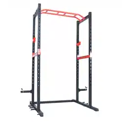
ASSEMBLY INSTRUCTIONS
We value your experience using Sunny Health and Fitness products. For assistance with parts or troubleshooting
STEP 1:
Attach 2 Stabilizers (No. 1) onto Bottom Connecting Frame (No. 3) using 4 Hexagon Bolts (No. 21), 4 Hex Lock Nuts (No. 22), 4 Flat Washers (No. 23) and 4 Flat Big Washers (No. 24). Secure with Open End Wrenches (No. 25). Do not tighten the 4 Hexagon Bolts (No. 21) during this step.
STEP 2:
Attach 2 Stabilizers (No. 1) onto 4 Upright Posts (No. 8) using 8 Hexagon Bolts (No. 21), 8 Hex Lock Nuts (No. 22) and 16 Flat Washer (No. 23). Secure with Open End Wrench (No. 25). Do not tighten the 8 Hexagon Bolts (No. 21) during this step.
Attach 4 Upright Posts (No. 8) onto 2 Top Connecting Frames (No. 2) using 8 Hexagon Bolts (No. 21), 8 Hex Lock Nuts (No. 22), 8 Flat Washers (No. 23) and 8 Flat Big Washers (No. 24). Secure with Open End Wrench (No. 25). Do not tighten the 8 Hexagon Bolts (No. 21) during this step.
STEP 3:
Attach Pull Up Bar (No. 6) onto 2 Top Connecting Frames (No. 2) using 6 Hexagon Bolts (No. 21), 6 Hex Lock Nuts (No. 22), 6 Flat Washers (No. 23) and 6 Flat Big Washers (No. 24). Secure with Open End Wrench (No. 25).
Now you can tighten all the Hexagon Bolts (No. 21) from STEP 1 & STEP 2.
STEP 4:
Insert 2 Counterweight Rods (No. 7) onto 2 Upright Posts (No. 8) using 4 Hexagon Bolts (No. 21), 4 Hex Lock Nuts (No. 22) and 8 Flat Washers (No. 23). Tighten and secure with Open End Wrench (No. 25).
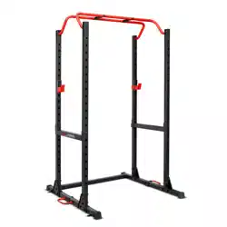
STEP 5:
Insert Right Safety Bar (No. 4) into Upright Post (No. 8) on the left. Turn the Right Safety Bar (No. 4) as the arrow showed on the left picture to tighten.
Insert Left Safety Bar (No. 5) into Upright Post (No. 8) on the right. Turn the Left Safety Bar (No. 5) as the arrow showed on the left picture to tighten.
Insert Right Hook (No. 9) into Upright Post (No. 8) on the left. Turn the Right Hook (No. 9) as the arrow showed on the picture to tighten.
Insert Left Hook (No. 10) into Upright Post (No. 8) on the right. Turn the Left Hook (No. 10) as the arrow showed on the left picture to tighten.
STEP 6:
WARNING: Please ensure sufficient weights are on the power zone strength rack and the power zone strength rack is bolted to the ground before using the resistance bands.
*NOTE: 013 Wood Screws and Expansion Bolts are not included.
If the ground is made of wood material, secure the 4 Connecting Pieces (No. A) on Stabilizers (No. 1) to the ground using 4 013 Wood Screws to bolt the power zone strength rack.
If the ground is cement ground, please mark the holes on the 4 Connecting Pieces (No. A), then remove the power zone strength rack, drill the holes and install 4 Expansion Bolts into the ground. Move the power zone strength rack back, align the holes with 4 Connecting Pieces (No. A) to the 4 Expansion Bolts and tighten them to bolt the power zone strength rack.
ADJUSTMENTS & USAGE GUIDE
ADJUSTING THE PULL UP BAR
The height of Pull Up Bar (No. 6) can be adjusted by changing the position of Top Connecting Frame (No. 2).
Adjustment step: repeat the installation steps of Top Connecting Frame (No. 2) in STEP 2 & STEP 3.
ADJUSTING THE SAFETY BAR
The height of the Left & Right Safety Bars (No. 5 & No. 4) can be adjusted.
Please ensure the Left & Right Safety Bars (No. 5 & No. 4) are the same height.
Adjustment steps: repeat the installation of Left & Right Safety Bars (No. 5 & No. 4) in STEP 5.
ADJUSTING THE HOOK
Left & Right Hooks (No. 10 & No. 9) can be installed on the rear Upright Post (No. 8) or on the front Upright Post (No. 8).
Please ensure the Left & Right Hooks (No. 10 & No. 9) are the same height.
Adjustment steps: repeat the installation of Left & Right Hooks (No. 10 & No. 9) in STEP 5.
MAINTENANCE INSTRUCTIONS
DAILY MAINTENANCE
Inspect and tighten all parts (Nuts, Bolts, Rubber Pads, Steel Brackets, etc.) regularly. Replace any worn or torn parts immediately.
Check and ensure the equipment is levelled at all time.
Check and tighten all adjustment pins/knobs regularly.
WEEKLY MAINTENANCE
Use damp cloth on plastic parts only, use dry cloth on metal frames. Inspect the metal frame structure of the equipment.
#1 Can i do decline bench presses with spotter bar?
I would say yes. The spotter bar can go down to about 18" off the ground.
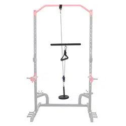
#2 Can you do seated row and tricep extension with this (cables)?
If they make the attachments I guess, but I recommend buying bands for those things
#3 What size hardware do use to secure this to a concrete floor?
It has four half inch holes on the base for bolting onto the floor. Don't use half inch bolts because you're maxing out the space of hole. Use a bolt diameter slightly smaller than half inch to give yourself some extra space to work with.
I do not have mine bolted down or on a indoor mat it’s just on the concrete floor in the garage and doesn’t move. If you want or think you need eco training stability it never hurts to bolt it to the ground but so far the rack has no lead me to think it needs to be bolted down
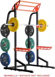
#7 Does the weight plate storage get in the way when using bands on the band pegs?
It depends upon the orientation of your rack. For me, it does not get in the way. I keep my 45's on the rack storage and it does not create an issue to use bands.