Specifications
AUDIO POWER SPECIFICATIONS
POWER OUTPUT AND TOTAL HARMONIC DISTORTION
35 watts per channel minimum continuous average power into 4 ohms,
both channels driven from 20 Hz to 20 kHz with no more than 0.04% total
harmonic distortion per Car Audio Ad Hoc Committee standards.
Other Specifications
Circuit system OTL (output transformerless) circuit
Pulse power supply
Inputs RCA pin jacks
High level input connector
Input level adjustment range
0.3 – 6 V (RCA pin jacks),
0.6 – 12 V (High level input)
Outputs Speaker terminals
Speaker impedance 2 – 8 Ω (stereo)
4 – 8 Ω (when used as a bridging amplifier)
Maximum output 100 W × 2 (at 4 Ω)
222 W (BTL, at 4 Ω)
Rated output (supply voltage at 14.4 V)
35
W × 2
(20 Hz – 20 kHz, 0.04 % THD, at 4
Ω
)
40
W × 2
(20 Hz – 20 kHz, 0.1 % THD, at 2
Ω
)
80 W (Monaural) (20 Hz – 20 kHz, 0.1 % THD, at 4 Ω)
Frequency response 5 Hz – 80 kHz ( dB)
Harmonic distortion 0.005 % or less (at 1 kHz, 4 Ω, 10 W)
Low-pass filter 80 Hz, –18 dB/oct
Power requirements 12 V DC car battery (negative ground)
Power supply voltage 10.5 – 16 V
Current drain
at rated output: 12 A (4
Ω
, 35 W × 2)
Remote input: 1.5 mA
Dimensions Approx. 205
×
55
×
158 mm (8
1
/8
×
2
1
/4
×
6
1
/4 in.) (w/h/d) not incl. projecting
parts and controls
Mass Approx. 1.6 kg (3 lb 9 oz.) not incl. accessories
Supplied accessories Mounting screws (4)
High level input cord (1)
Protection cap (1)
Design and specifications are subject to change without notice.
Features
•Maximum power output of 100 watts per channel (at 4 Ω).
•This unit can be used as a monaural amplifier with a maximum output of 222 watts.
•Dual mode connection possible for a multi-speaker system.
•Built in Low-pass filter (80 Hz, –18dB/oct).
•Built in protection circuit*.
•Pulse power supply** for stable and regulated output power.
•Direct connection can be made with the speaker output of your car audio if it is not equipped with
the line output (High level input connection).
* Protection circuit
This amplifier is provided with a protection circuit that operates in the following cases:
— when the unit is overheated
— when a DC current is generated
— when the speaker terminals are short circuited.
The color of the POWER/PROTECTOR indicator will change from green to red, and the unit will shut down.
If this happens, turn off the connected equipment, take out the cassette tape or disc, and determine the
cause of the malfunction. If the amplifier has overheated, wait until the unit cools down before use.
** Pulse power supply
This unit has a built-in power regulator which converts the power supplied by the 12 V DC car battery into
high speed pulses using a semiconductor switch. These pulses are stepped up by the built-in pulse
transformer and separated into both positive and negative power supplies before being converted into
direct current again. This is to regulate fluctuating voltage from the car battery. This light weight power
supply system provides a highly efficient power supply with a low impedance output.
Installation
Before Installation
•Mount the unit either inside the trunk or under a seat.
•Choose the mounting location carefully so the unit will not interfere with the normal movements of
the driver and it will not be exposed to direct sunlight or hot air from the heater.
•Do not install the unit under the floor carpet, where the heat dissipation from the unit will be
considerably impaired.
First, place the unit where you plan to install it, and mark the positions of the four screw holes on the
mounting board (not supplied). Then drill a 3 mm (
1
/8 in.) pilot hole at each mark and mount the unit
onto the board with the supplied mounting screws. The mounting screws are all 15 mm (
19
/32 in.) long,
so make sure that the mounting board is thicker than 15 mm (
19
/32 in.).
Fuse Replacement
If the fuse blows, check the power connection and replace the fuse. If the fuse blows again after
replacement, there may be an internal malfunction. In such a case, consult your nearest Sony dealer.
Warning
When replacing the fuse, be sure to use one matching the amperage stated above the fuse holder.
Never use a fuse with an amperage rating exceeding the one supplied with the unit as this could
damage the unit.
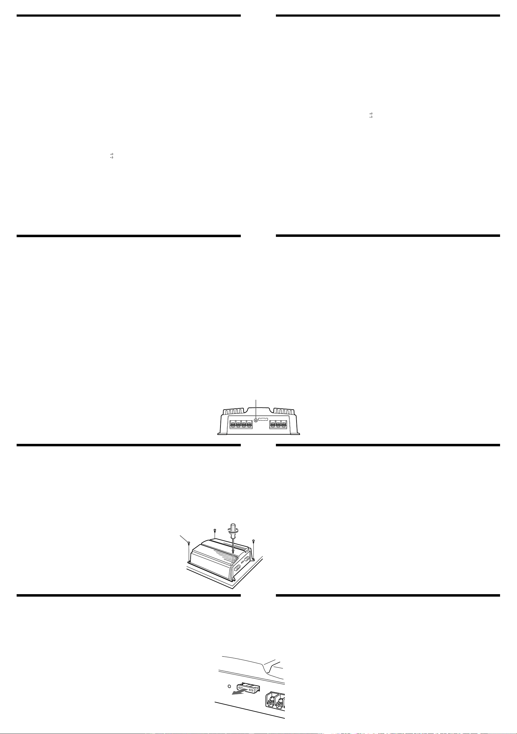
POWER/PROTECTOR indicator
Indicateur POWER/PROTECTOR
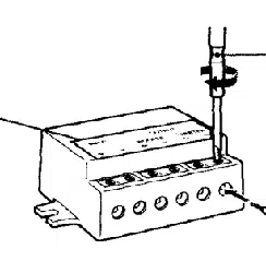
Mount the unit as illustrated.
Installez l’appareil comme illustré.
1
Spécifications
Circuiterie Circuit OTL (sortie sans transformateur)
Alimentation électrique par impulsions
Entrées Prises à broche RCA
Connecteur d’entrée haut niveau
Plage de réglage du niveau d’entrée
0,3 à 6 V (prises à broche RCA),
0,6 à 12 V (entrée haut niveau)
Sorties Bornes de haut-parleurs
Impédance des haut-parleurs
2 à 8 Ω (stéréo)
4 à 8 Ω (utilisé comme amplificateur en pont)
Sortie maximale 100 W × 2 (à 4 Ω)
222 W (BTL, à 4 Ω)
Sortie nominale (tension d’alimentation de 14,4 V)
35 W × 2 (20 Hz à 20 kHz, 0,04 % DHT, à 4 Ω)
40 W × 2 (20 Hz à 20 kHz, 0,1 % DHT, à 2 Ω)
80 W (mono) (20 Hz à 20 kHz, 0,1 % DHT, à 4 Ω)
Réponse en fréquence 5 Hz à 80 kHz ( dB)
Distorsion harmonique 0,005 % ou moins (à 1 kHz, 4 Ω, 10 W)
Filtre passe-bas 80 Hz, –18 dB/oct
Alimentation requise Batterie de voiture, 12 V CC (masse négative)
Tension d’alimentation 10,5 à 16 V
Consommation de courant à la sortie nominale : 12 A (4 Ω, 35 W × 2)
Entrée de télécommande : 1,5 mA
Dimensions Env. 205 × 55 × 158 mm (8
1
/8
×
2
1
/4
×
6
1
/4 po.) (l/h/p) (parties saillantes et
commandes exclues)
Poids Env. 1,6 kg (3 lb 9 on.), accessoires non compris
Accessoires fournis Vis de montage (4)
Cordon d’entrée haut niveau (1)
Cache de protection (1)
La conception et les spécifications sont sujettes à modification sans préavis.
Caractéristiques
•Puissance de sortie maximale de 100 watts par canal (à 4 Ω).
•Cet appareil peut être utilisé comme amplificateur mono avec une sortie maximale de 222 watts.
•Une connexion double est possible pour un autoradio à plusieurs haut-parleurs.
•Filtre passe-bas intégré (80 Hz, –18 dB/oct).
•Circuit de protection intégré*.
•Alimentation électrique par impulsions** pour une puissance de sortie stable et régulée.
•Il est possible d’établir une connexion directe avec la sortie de haut-parleur de votre autoradio si
celui-ci n’est pas équipé d’une sortie de ligne (connexion d’entrée haut niveau).
* Circuit de protection
Cet amplificateur est fourni avec un circuit de protection qui entre en fonction dans les cas suivants :
— lorsque l’appareil surchauffe
— lorsqu’un courant continu est généré
— lorsque les bornes de haut-parleur sont court-circuitées.
La couleur de l’indicateur POWER/PROTECTOR passe du vert au rouge et l’appareil s’éteint.
Dans ce cas, éteignez les appareils raccordés, retirez la cassette ou le disque et déterminez l’origine du
problème. Si l’amplificateur surchauffe, attendez qu’il refroidisse avant d’utiliser l’appareil.
** Alimentation électrique par impulsions
Cet appareil est équipé d’un régulateur de puissance intégré qui convertit la puissance fournie par la
batterie de voiture de 12 V CC en impulsions ultra-rapides au moyen d’un commutateur à semi-conducteur.
Ces impulsions sont amplifiées par le transformateur d’impulsions intégré et séparées en alimentation
positive et négative avant d’être reconverties en courant continu. Ce processus permet de compenser les
fluctuations de tension provenant de la batterie de la voiture. Ce système d’alimentation léger assure une
alimentation électrique très efficace pour une sortie d’impédance faible.
Installation
Avant l’installation
•Installez l’appareil dans le coffre ou sous un siège.
•Choisissez soigneusement l’emplacement de montage afin d’éviter que l’appareil ne gêne le
conducteur dans ses mouvements et qu’il ne soit pas exposé au rayonnement direct du soleil ni aux
conduits de chauffage.
•N’installez pas l’appareil sous le tapis de sol car la dissipation thermique ne pourrait pas se faire
correctement.
Posez d’abord l’appareil à l’endroit où vous souhaitez l’installer et tracez un repère de positionnement
pour les quatre orifices de vis sur la plaque de montage (non fournie). Percez des orifices de 3 mm
(
1
/8 po.) au niveau de chaque repère et fixez l’appareil sur la plaque avec les vis de montage fournies.
La longueur des vis de montage est de 15 mm (
19
/32 po.). Assurez-vous donc que l’épaisseur de la
plaque de montage est supérieure à 15 mm (
19
/32 po.).
Remplacement du fusible
Si le fusible fond, vérifiez les connexions de l’alimentation et remplacez le fusible. Si le fusible fond de
nouveau après avoir été remplacé, cela peut révéler une défaillance interne de l’appareil. Dans ce cas,
consultez votre détaillant Sony le plus proche.
Avertissement
Lorsque vous remplacez le fusible, veillez à utiliser un fusible dont la capacité en ampères correspond
à celle inscrite sur le porte-fusible. N’utilisez jamais de fusible dont la capacité dépasse celle du fusible
fourni avec l’appareil car cela pourrait endommager l’appareil.
Cause/Solution
The fuse is blown. t Replace the fuse with a new one.
The ground lead is not securely connected. t Fasten the
ground lead securely to a metal point of the car.
The voltage going into the remote terminal is too low.
•The connected master unit is not turned on.
t Turn on the master unit.
•The system employs too many amplifiers. t Use a relay.
Check the battery voltage (10.5 – 16 V).
Use speakers with suitable impedance.
•Stereo operation: 2 – 8 Ω
•Bridging operation: 4 – 8 Ω
The speaker outputs are short-circuited.
t Rectify the cause of the short-circuit.
The power connecting leads are installed too close to the
RCA pin cords. t Keep the leads away from the cords.
The ground lead is not securely connected. t Fasten the
ground lead securely to a metal point of the car.
Speaker leads are touching the car chassis.
t Keep the leads away from the car chassis.
2002 Sony Corporation Printed in China
3-243-396-11 (1)
Operating instructions
Mode d’emploi
XM-222W
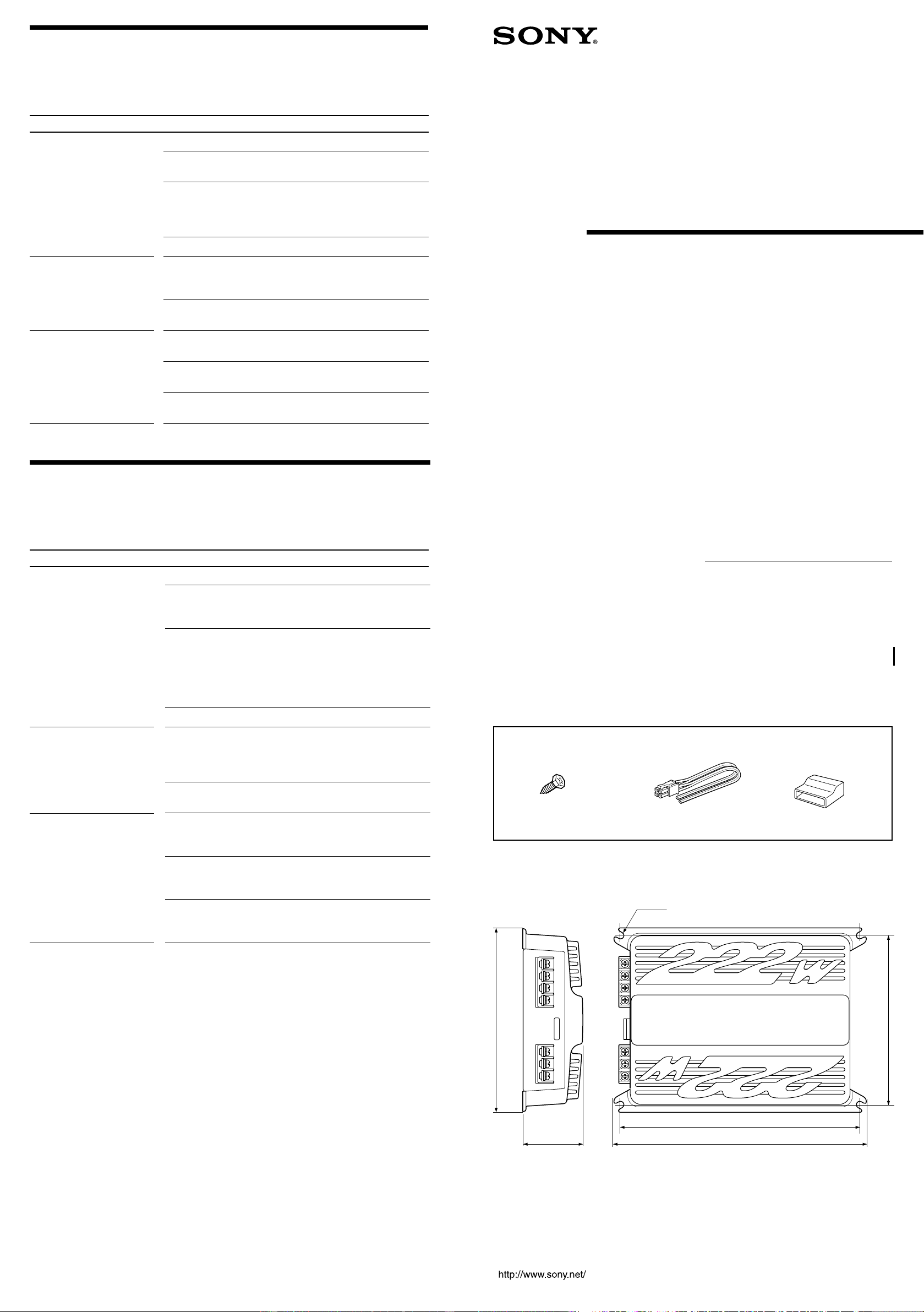
Parts for Installation and Connections
Pièces destinées à l’installation et aux raccordements
12
3
(× 4)
0.2 m
Dimensions
Dimensions
Unit: mm (in.)
Unité : mm (po.)
154 (6
1
/
8
)
168
(6
5
/
8
)
φ6 (
1
/4)
218
(8
5
/8)
230 (9
1
/8)
55
(2
1
/4)
Troubleshooting guide
The following checklist will assist in the correction of most problems which you may
encounter with your unit.
Before going through the checklist below, refer to the connection and operating
procedures.
Problem
The POWER/PROTECTOR
indicator does not light
up.
•The POWER/PROTECTOR
indicator will change
from green to red.
•The unit becomes
abnormally hot.
Alternator noise is heard.
φ5 × 15
Stereo Power
Amplifier
Guide de dépannage
La liste de contrôle suivante vous aidera à résoudre la plupart des problèmes que vous
pouvez rencontrer avec cet appareil.
Avant de passer en revue la liste de contrôle ci-dessous, vérifiez les connexions et les
procédures d’utilisation.
Cause/Solution
Le fusible est fondu. t Remplacez le fusible par un neuf.
Le fil de masse n’est pas connecté correctement. t Fixez
solidement le fil de masse à un point métallique de la
carrosserie.
La tension entrant à la borne de la télécommande est trop
faible.
•L’appareil principal connecté n’est pas allumé.
t Mettez l’appareil principal sous tension.
•Le système utilise trop d’amplificateurs. t Utilisez un
relais.
Vérifiez la tension de batterie (10,5 à 16 V).
Utilisez des haut-parleurs dont l’impédance convient à
l’appareil.
•Fonctionnement en stéréo : 2 à 8 Ω
•Fonctionnement en pont : 4 à 8 Ω
Les sorties des haut-parleurs sont court-circuitées.
t Corrigez la cause du court-circuit.
Les câbles de raccordement électrique sont installés trop
près des câbles à broches RCA. t Éloignez ces câbles les
uns des autres.
Le fil de masse n’est pas connecté correctement. t Fixez
solidement le fil de masse à un point métallique de la
carrosserie.
Les fils des haut-parleurs touchent la carrosserie de la
voiture.
t Éloignez les fils de la carrosserie de la voiture.
Problème
L’indicateur POWER/
PROTECTOR ne s’allume
pas.
•L’indicateur POWER/
PROTECTOR passe du
vert au rouge.
•L’appareil chauffe de
façon anormale.
L’alternateur émet un
bruit.
Owner’s Record
The model and serial numbers are located on the bottom of the unit.
Record the serial number in the space provided below.
Refer to these numbers whenever you call upon your Sony dealer regarding this product.
Model No. XM-222W Serial No.
Connections
Precautions
•This unit is designed for negative ground 12 V DC operation only.
•Use speakers with an impedance of 2 to 8 Ω (4 to 8 Ω when used as a bridging amplifier).
•Do not connect any active speakers (with built-in amplifiers) to the speaker terminals of the unit. Doing
so may damage the active speakers.
• Avoid installing the unit in areas subject to:
— high temperatures such as from direct sunlight or hot air from the heater
— rain or moisture
— dust or dirt.
•If your car is parked in direct sunlight and there is a considerable rise in temperature inside the car, allow
the unit to cool down before use.
•When installing the unit horizontally, be sure not to cover the fins with the floor carpet etc.
• If this unit is placed too close to the car radio or antenna, interference may occur. In this case, relocate the
amplifier away from the car radio or antenna.
• If no power is being supplied to the master unit, check the connections.
•This power amplifier employs a protection circuit to protect the transistors and speakers if the amplifier
malfunctions. Do not attempt to test the protection circuits by covering the heat sink or connecting
improper loads.
• Do not use the unit on a weak battery as its optimum performance depends on a good power supply.
• For safety reasons, keep your car audio volume moderate so that you can still hear sounds outside your
car.
If you have any questions or problems concerning your unit that are not covered in this manual, please
consult your nearest Sony dealer.
Caution
•Before making any connections, disconnect the ground terminal of the car battery to avoid short circuits.
•Be sure to use speakers with an adequate power rating. If you use small capacity speakers, they may be
damaged.
•Do not connect the # terminal of the speaker system to the car chassis, and do not connect the #
terminal of the right speaker with that of the left speaker.
•Install the input and output cords away from the power supply lead as running them close together can
generate some interference noise.
•This unit is a high powered amplifier. Therefore, it may not perform to its full potential if used with the
speaker cords supplied with the car.
•If your car is equipped with a computer system for navigation or some other purpose, do not remove the
ground wire from the car battery. If you disconnect the wire, the computer memory may be erased. To
avoid short circuits when making connections, disconnect the +12 V power supply lead until all the other
leads have been connected.
Connexions
Précautions
• Cet appareil est conçu pour fonctionner uniquement sur un courant de 12 V CC avec masse négative.
• Utilisez des haut-parleurs d’une impédance appropriée de 2 à 8 Ω (4 à 8 Ω si utilisé comme amplificateur
en pont).
• Ne raccordez pas de haut-parleurs actifs (avec amplificateurs intégrés) aux bornes de haut-parleurs de
cet appareil. Cela risquerait en effet d’endommager les haut-parleurs actifs.
• N’installez pas l’appareil dans des endroits soumis :
—à des températures élevées, comme en plein soleil ou près du chauffage ;
—à la pluie ou à l’humidité ;
—à la poussière ou à la saleté.
• Si votre voiture est garée en plein soleil et que la température a considérablement augmenté à l’intérieur
de l’habitacle, laissez l’appareil refroidir avant de l’utiliser.
• Si vous installez l’appareil à l’horizontale, ne recouvrez pas les ailettes de ventilation avec le tapis de sol
ou quoi que ce soit d’autre.
• Si cet appareil est placé trop près de l’autoradio ou de l’antenne de voiture, des interférences risquent de
se produire. Dans ce cas, éloignez l’amplificateur de l’autoradio ou de l’antenne de voiture.
• Si l’appareil principal ne reçoit pas de courant, vérifiez les connexions.
• Cet amplificateur de puissance est équipé d’un circuit de protection conçu pour protéger les transistors et
les haut-parleurs en cas de défaillance de l’amplificateur. N’essayez pas de tester l’efficacité des circuits
de protection en recouvrant le dissipateur thermique ou en effectuant de mauvaises connexions.
• N’utilisez pas l’appareil avec une batterie faible, car sa performance optimale dépend d’une bonne
alimentation en électricité.
• Pour des raisons de sécurité, maintenez le volume de l’autoradio à un niveau modéré afin d’entendre les
bruits extérieurs.
Si vous avez des questions ou des problèmes concernant le fonctionnement de cet appareil qui ne sont pas
abordés dans ce manuel, consultez votre détaillant Sony le plus proche.
Avertissement
• Avant d’effectuer les connexions, débranchez la borne de masse de la batterie de voiture pour éviter de
provoquer un court-circuit.
• Utilisez des haut-parleurs d’une capacité adéquate. Si vous utilisez des haut-parleurs de faible capacité,
ils risquent d’être endommagés.
• Ne raccordez pas la borne # du système de haut-parleurs à la carrosserie de la voiture, ni la borne # du
haut-parleur droit à celle du haut-parleur gauche.
• Éloignez les cordons d’entrée et de sortie du fil d’alimentation électrique afin d’éviter que des
interférences ne se produisent.
• Cet appareil est un amplificateur de haute puissance. Il se peut donc qu’il n’atteigne pas sa puissance
maximale s’il est utilisé avec les cordons de haut-parleurs de la voiture.
• Si votre voiture est équipée d’un ordinateur de bord pour la navigation ou autre, ne débranchez pas le fil
de masse de la batterie de la voiture. Si vous débranchez ce fil, toute la mémoire de l’ordinateur risque
d’être effacée. Pour éviter tout risque de court-circuit lorsque vous effectuez les raccordements, branchez
le fil d’alimentation de +12 V uniquement après avoir branché tous les autres fils.
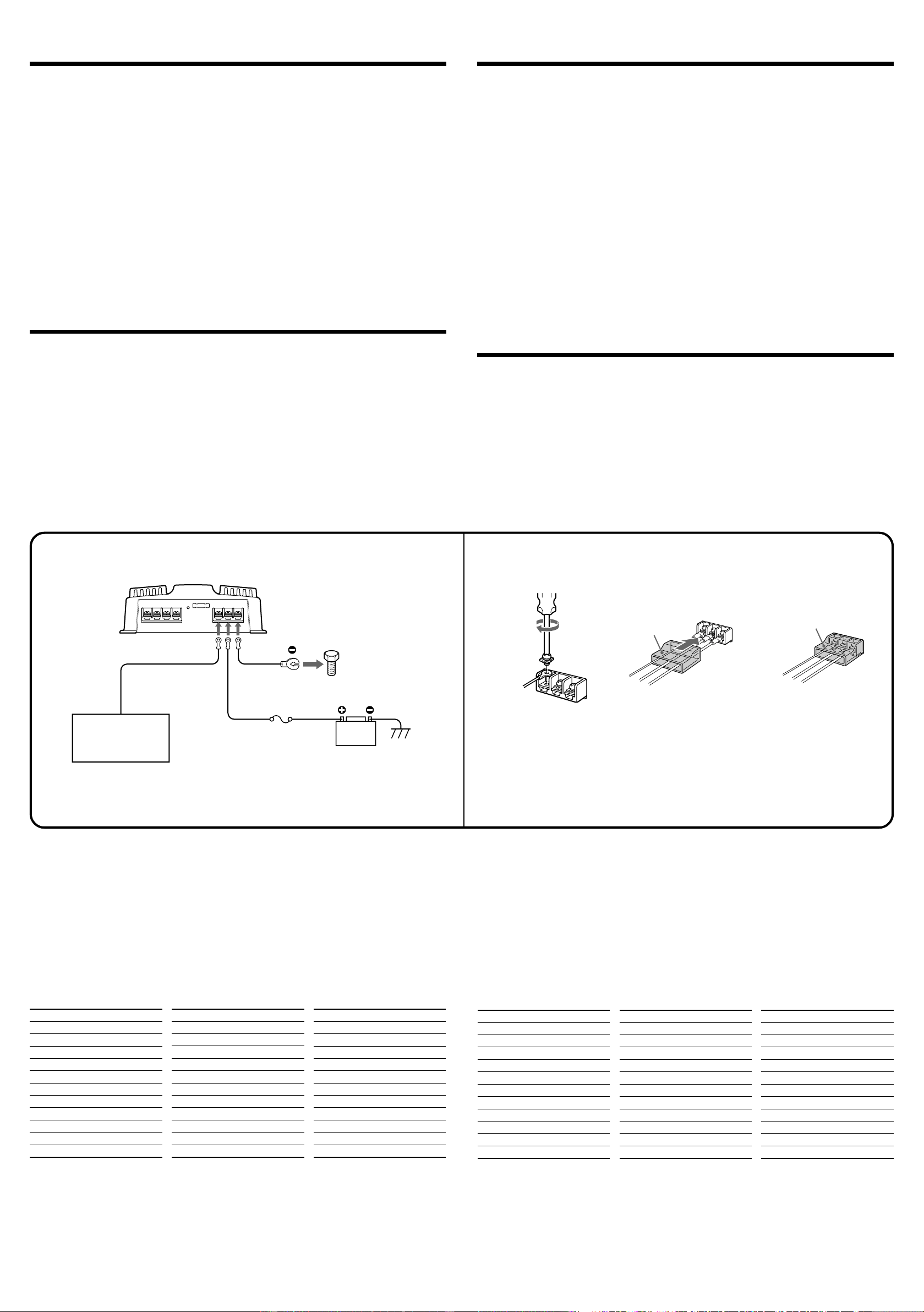
Power Connection Leads (not supplied)
Câbles d’alimentation (non fournis)
Fuse (20 A)
Fusible (20 A)
+12 V car battery
Batterie de voiture de +12 V
Car audio
Autoradio
to a metal point of the car
vers un point métallique de
la carrosserie
R
E
M
O
U
T
+
1
2
V
G
N
D
REM OUT
+
1
2
V
G
N
D
3
3
Notes on the power supply
• Connect the +12 V power supply lead only after all the other leads have been connected.
• Be sure to connect the ground lead of the unit securely to a metal point of the car. A loose connection
may cause a malfunction of the amplifier.
• Be sure to connect the remote control lead of the car audio to the remote terminal.
• When using a car audio without a remote output on the amplifier, connect the remote input terminal
(REMOTE) to the accessory power supply.
• Use a power supply lead with a fuse attached (20 A).
• Place the fuse in the power supply lead as close as possible to the car battery.
• During full-power operation, a current of more than 20 A will run through the system. Therefore, make
sure that the leads to be connected to the +12 V and GND terminals of this unit are larger than 14-Gauge
(AWG-14) or have a sectional area of more than 2 mm
2
.
Remarques sur l’alimentation électrique
• Raccordez le câble d’alimentation +12 V uniquement après avoir réalisé toutes les autres connexions.
• Raccordez solidement le fil de masse de l’appareil à un point métallique de la carrosserie. Une connexion
lâche risque de provoquer un problème de fonctionnement de l’amplificateur.
• Veillez à raccorder le fil de télécommande de l’autoradio à la borne de télécommande.
• Si vous utilisez un autoradio dont l’amplificateur ne comporte pas de sortie de télécommande, raccordez
la borne d’entrée de la télécommande (REMOTE) à la prise d’alimentation des accessoires.
• Utilisez un câble d’alimentation muni d’un fusible (20 A).
• Placez le fusible du câble d’alimentation le plus près possible de la batterie de la voiture.
• Pendant une utilisation à pleine puissance, un courant d’une intensité supérieure à 20 A circule dans le
système. Assurez-vous donc que les câbles à raccorder aux bornes +12 V et GND de cet appareil sont de
calibre supérieur à 14 (AWG-14) ou d’une section supérieure à 2 mm
2
.
Remote output*
Sortie de télécommande*
(REM OUT)
* If you have the factory original or some other car
audio without a remote output on the amplifier,
connect the remote input terminal (REMOTE) to the
accessory power supply.
Make the terminal connections as illustrated below.
Effectuez les connexions des bornes comme illustré ci-dessous.
Faites passer les fils par le cache, raccordez
les fils, puis recouvrez les bornes avec le
cache.
Remarque
Lorsque vous vissez la vis, faites attention à ne pas
appliquer une trop grande force*, car cela pourrait
endommager la vis.
* Le couple de torsion doit être inférieur à 1 N•m.
Pass the leads through the cap, connect the
leads, then cover the terminals with the
cap.
Note
When you tighten the screw, be careful not to apply
too much torque* as doing so may damage the screw.
* The torque value should be less than 1 N•m.
c
Notes
• When using passive crossover networks in a multi-speaker system, care must be taken as the speaker system’s impedance
should not be lower than that of the suitable impedance for this unit.
• When you are installing a 12 decibels/octave system in your car, the following points must be considered. In a 12 decibels/
octave system where both a choke and capacitor are used in series to form a circuit, great care must be taken when they
are connected. In such a circuit, there is going to be an increase in the current which bypasses the speaker with frequencies
around the crossover frequency. If audio signals continue to be fed into the crossover frequency area, it may cause the
amplifier to become abnormally hot or the fuse to blow. Also if the speaker is disconnected, a series-resonant circuit will be
formed by the choke and the capacitor. In this case, the impedance in the resonance area will decrease dramatically
resulting in a short circuit situation causing damage to the amplifier. Therefore, make sure that a speaker is connected to
such a circuit at all times.
Remarques
• Lorsque des réseaux à transition passive sont utilisés dans un système à plusieurs haut-parleurs, il faut prendre certaines
précautions afin que l’impédance du système de haut-parleurs ne soit pas inférieure à l’impédance convenant à cet
appareil.
• Lors de l’installation d’un système à 12 dB/oct dans votre véhicule, prenez en compte les points suivants. Dans un système à
12 dB/oct où un volet d’air et un condensateur sont utilisés en série pour former un circuit, prenez toutes les précautions
nécessaires au moment de leur raccordement. Dans un circuit de ce type, il y a une augmentation du courant qui passe au
niveau du haut-parleur. Les fréquences sont alors proches de la fréquence de transition. Si des signaux audio proches de la
fréquence de transition continuent d’arriver, l’amplificateur risque de chauffer de façon anormale ou le fusible de fondre.
De même, si le haut-parleur est débranché, un circuit résonnant série est formé par le volet d’air et le condensateur. Dans
ce cas, l’impédance de la zone de résonance diminue considérablement, ce qui entraîne un court-circuit qui endommage
l’amplificateur. Par conséquent, assurez-vous que le haut-parleur est toujours raccordé à un circuit de ce type.
* Si vous disposez de l’autoradio d’origine ou d’un
autre autoradio dont l’amplificateur ne comporte pas
de sortie de télécommande, raccordez la borne
d’entrée de télécommande (REMOTE) à la prise
d’alimentation des accessoires.
Crossover Frequency unit: Hz
50
80
100
130
150
200
260
400
600
800
1000
* Not supplied
L (coil)
*
unit: mH
12.7
8.2
6.2
4.7
4.2
3.3
2.4
1.6
1.0
0.8
0.6
C1/C2 (capacitor)
*
unit: µF
800
500
400
300
270
200
150
100
68
50
39
Table of crossover values for 6 dB/octave (4 ohms) (Speaker Connections 4)
Fréquence de transition unité : Hz
50
80
100
130
150
200
260
400
600
800
1000
* Non fourni
L (bobine)
*
unité : mH
12,7
8,2
6,2
4,7
4,2
3,3
2,4
1,6
1,0
0,8
0,6
C1/C2 (condensateur)
*
unité : µF
800
500
400
300
270
200
150
100
68
50
39
Tableau des valeurs de transition pour 6 dB/oct (4 ohms)
(Connexions des haut-parleurs 4
)
BTL
(80Hz)
OFF ON
LPF
(80Hz)
OFF ON
LPF
BTL BTLBTL
(80Hz)
OFF ON
LPF
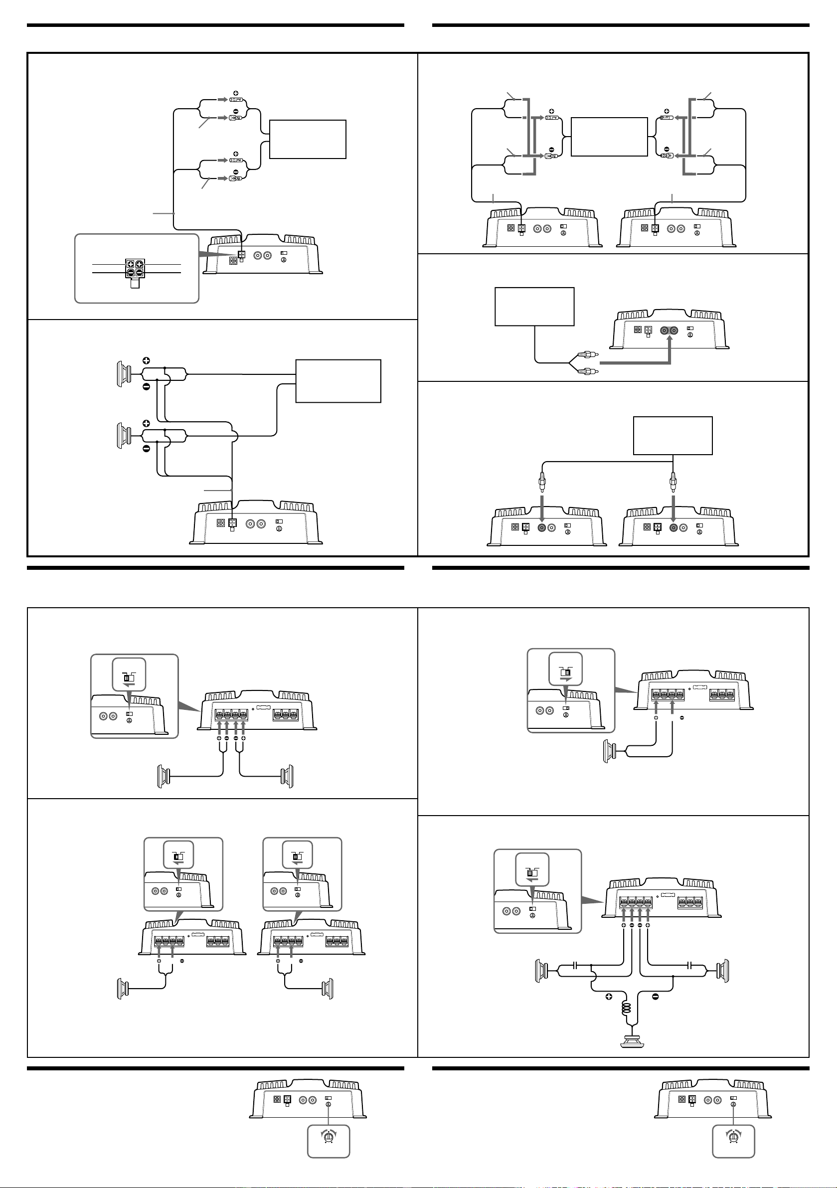
Input Connections
Speaker Connections
Turn on or off the LPF switch at the unit rear as illustrated below.
Connexions d’entrée
Connexions des haut-parleurs
Réglez le commutateur LPF situé à l’arrière de l’appareil à ON ou OFF, comme indiqué dans l’illustration ci-dessous.
High Level Input Connection
(with Speaker Connection 1 or 4)
Connexion d’entrée à haut niveau
(avec connexion de haut-parleur 1 ou 4)
AA
AA
A
High Level Input Connection (with Speaker Connection 3)
Connexion d’entrée à haut niveau (avec connexion de haut-parleur 3)
BB
BB
B
High Level Input Connection (with Speaker Connection 2)
Connexion d’entrée à haut niveau (avec connexion de haut-parleur 2)
Line Input Connection (with Speaker Connection 1, 2, 4)
Connexion d’entrée de ligne
(avec connexion de haut-parleur 1, 2
ou 4)
Line Input Connection (with Speaker Connection 3)
Connexion d’entrée de ligne (avec connexion de haut-parleur 3)
CC
CC
C
DD
DD
D
EE
EE
E
(80Hz)
OFF ON
LPF
Right speaker
Haut-parleur droit
Left speaker
Haut-parleur gauche
White
Blanc
Gray
Gris
2
Striped
Rayé
Striped
Rayé
2-Speaker System (with Input Connection A, D)
Système à 2 haut-parleurs (avec connexion d’entrée A
ou
D)
11
11
1
Note
Make sure that the line output from the car
audio is connected to the jack marked
“L (BTL)” on the unit.
Notes
If you wish to use a subwoofer as the monaural speaker,
connect the speaker as illustrated above. The output
signals to the subwoofer will be a combination of both
the right and left output signals.
Left speaker output
Sortie de haut-parleur gauche
Right speaker output
Sortie de haut-parleur droit
Striped
Rayé
Striped
Rayé
Car audio
Autoradio
White
Blanc
Gray
Gris
White
Blanc
White striped
Rayé blanc
Gray striped
Rayé gris
Gray
Gris
2
RL
Left speaker output
Sortie de haut-parleur
gauche
Right speaker output
Sortie de haut-parleur
droit
Striped
Rayé
Striped
Rayé
Striped
Rayé
Striped
Rayé
Car audio
Autoradio
22
LINE OUT
Right channel
Canal droit
Left channel
Canal gauche
LINE OUT
Left speaker (min. 2 Ω)
Haut-parleur gauche (min. 2 Ω)
Right speaker (min. 2 Ω)
Haut-parleur droit (min. 2 Ω)
Subwoofer (with Input Connection C, D)
Caisson de graves (avec connexion d’entrée C
ou
D)
22
22
2
1-Speaker System (with Input Connection B, E)
Système à 1 haut-parleur (avec connexion d’entrée B
ou
E)
33
33
3
C1
C2
L
Subwoofer
Caisson de graves
Left speaker
Haut-parleur gauche
Right speaker
Haut-parleur droit
Dual Mode System (with a Bridged Subwoofer A, D)
Système double (avec caisson de graves en pont A
ou
D)
44
44
4
(80Hz)
OFF ON
LPF
BTLBTL
Subwoofer (min. 4 Ω)
Caisson de graves (mín. 4 Ω)
Right speaker
(min. 4 Ω)
Haut-parleur droit
(min. 4 Ω)
Left speaker
(min. 4 Ω)
Haut-parleur gauche
(min. 4 Ω)
L (BTL) L (BTL)
Remarques
Afin d’utiliser le caisson de graves comme haut-parleur
mono, raccordez le haut-parleur comme indiqué dans
l’illustration ci-dessus. Les signaux de sortie parvenant au
caisson de graves sont une combinaison des signaux de
sortie gauche et droit.
Remarque
Assurez-vous que la sortie de ligne de l’autoradio est
raccordée à la prise marquée
“L (BTL)” sur l’appareil.
Car audio
Autoradio
Car audio
Autoradio
Car audio
Autoradio
The input level can be adjusted with this control
when using source equipment made by other
manufacturers. Turn it to MAX when the output
level of the car audio seems low.
Le niveau d’entrée peut être réglé avec cette
commande lors de l’utilisations d’appareils
sources d’autres fabricants. Réglez cette
commande à la position MAX lorsque le niveau
de sortie de l’autoradio semble faible.
MAXMIN
LEVEL
Level Adjustment Control Commande de niveau
MAXMIN
LEVEL