

PMS 419
Owner's Manual
for Maintenance and Safety
Read this manual carefully. It contains important safety information.
This is an adult vehicle only.
Operation is prohibited for those under 16 years of age.
2017
TRACTOR
Sportsman
® 450 HO
Sportsman
® 570
Sportsman
® 570 EPS
Sportsman
® Touring 570 EPS
Sportsman
® X2 570
Sportsman
® X2 570 EPS

1
2017 Tractor Owner’s Manual
Sportsman® 450 HO
Sportsman® 570
Sportsman® 570 EPS
Sportsman® Touring 570 EPS
Sportsman® X2 570
Sportsman® X2 570 EPS

2
POLARIS® and SPORTSMAN® are trademarks of POLARIS Industries Inc.
Copyright 2016 POLARIS Industries Inc. All information contained within this
publication is based on the latest product information at the time of publication. Due to
constant improvements in the design and quality of production components, some minor
discrepancies may result between the actual vehicle and the information presented in
this publication. Depictions and/or procedures in this publication are intended for
reference use only. No liability can be accepted for omissions or inaccuracies. Any
reprinting or reuse of the depictions and/or procedures contained within, whether whole
or in part, is expressly prohibited.
The original instructions for this vehicle are in English. Other languages are provided as
translations of the original instructions.
This owner’s manual complies with ISO 3600:1996 (3) with the exception of section 4.3
(Machine Identification).
Owner’s Manual P/N 9927260

3
TABLE OF CONTENTS
Introduction . . . . . . . . . . . . . . . . . . . . . . . . . . . . 4
Safety . . . . . . . . . . . . . . . . . . . . . . . . . . . . . . . . . 8
Features and Controls. . . . . . . . . . . . . . . . . . . 24
Operation . . . . . . . . . . . . . . . . . . . . . . . . . . . . . 53
Winch Guide . . . . . . . . . . . . . . . . . . . . . . . . . . . 78
Emission Control Systems . . . . . . . . . . . . . . . 90
Maintenance . . . . . . . . . . . . . . . . . . . . . . . . . . . 91
POLARIS Products. . . . . . . . . . . . . . . . . . . . . 145
Specifications. . . . . . . . . . . . . . . . . . . . . . . . . 146
Troubleshooting . . . . . . . . . . . . . . . . . . . . . . . 153
Warranty . . . . . . . . . . . . . . . . . . . . . . . . . . . . . 158
Maintenance Log . . . . . . . . . . . . . . . . . . . . . . 163
Index . . . . . . . . . . . . . . . . . . . . . . . . . . . . . . . . 166

4
INTRODUCTION
Thank you for purchasing a POLARIS vehicle, and welcome to our
world-wide family of POLARIS enthusiasts. Be sure to visit us online at
www.polaris.com for the latest news, new product introductions,
upcoming events, career opportunities and more.
Here at POLARIS we proudly produce an exciting line of utility and
recreational products.
Always follow the instructions and recommendations in this manual.
The manual contains instructions for minor maintenance, but
information about major repairs is outlined in the POLARIS Service
Manual and should be performed only by a factory-certified Master
Service Dealer® (MSD) technician. Please see your dealer for all of
your service needs during (and after) the warranty period.
• Snowmobiles • RZR® sport vehicles
• All-terrain vehicles (ATVs) • GEM® electric vehicles
• Low emission vehicles (LEVs) • VICTORY® motorcycles
• RANGER® utility vehicles • INDIAN® motorcycles
•BRUTUS® work vehicles • POLARIS POWER® generators
• S
LINGSHOT® three wheel
motorcycles
• POLARIS DEFENSE® combat
vehicles

5
INTRODUCTION
The following signal words and symbols appear throughout this manual
and on your vehicle. Your safety is involved when these words and
symbols are used. Become familiar with their meanings before reading
the manual.
The safety alert symbol indicates a potential personal injury hazard.
DANGER
A DANGER indicates a hazardous situation that, if not avoided, will result in
death or serious injury.
WARNING
A WARNING indicates a hazardous situation that, if not avoided, could result in
death or serious injury.
CAUTION
A CAUTION indicates a hazardous situation that, if not avoided, could result in
minor or moderate injury.
NOTICE
A NOTICE indicates a situation that could result in property damage.
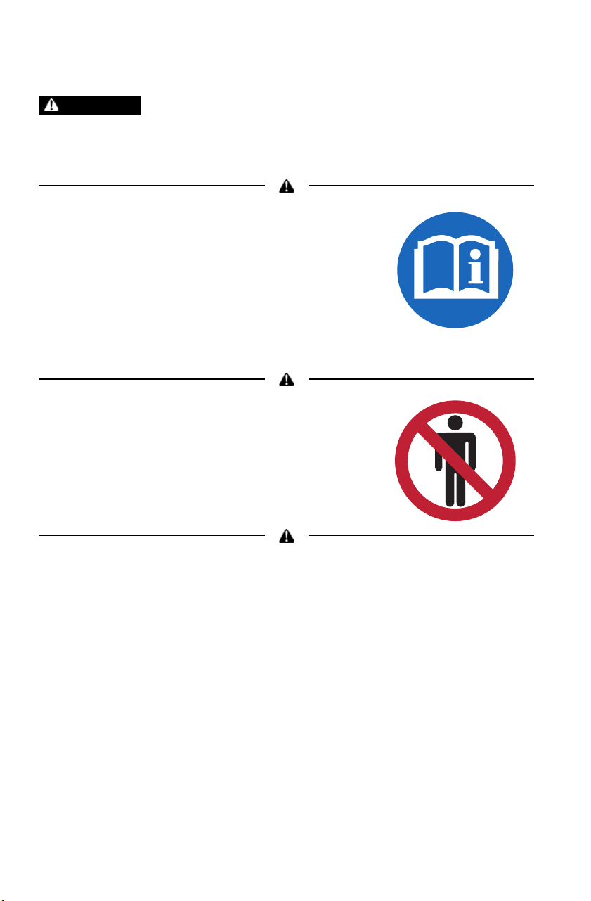
The Prohibition Safety Sign indicates an action NOT to take in order
to avoid a hazard.
The Mandatory Action Sign indicates an action that NEEDS to be
taken to avoid a hazard.

6
INTRODUCTION
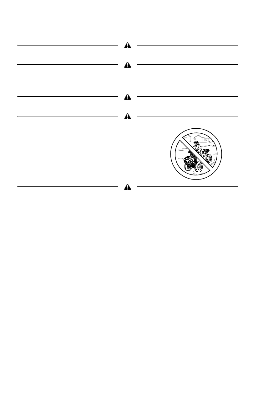
Failure to follow the warnings in this manual can result in serious injury or death.
A POLARIS Tractor is not a toy and can be hazardous to operate. A collision or
rollover can occur quickly, even during routine maneuvers, if you fail to take
proper precautions.
• Read this owner’s manual. Understand all safety warnings, precautions and
operating procedures before operating a POLARIS Tractor.
• Never operate this vehicle without proper instruction. Take a training course.
• This vehicle is an ADULT VEHICLE ONLY. Operation is prohibited for anyone
under 16 years of age.
• The Tractor is not equipped with attachment points for a front-end loader.
Attachment of a front-end loader is strictly prohibited.
• The Tractor is not equipped with a Falling Objects Protective Device.
• The Tractor is not equipped with protection against hazardous substances.
• Avoid operating in a manner that could result in an overturn, including, but not
limited to:
> Operating without instruction
> Operating when under the age of 16
> Operating while under the influence of drugs or alcohol
> Accelerating or braking excessively or abruptly
> Turning sharply or turning at excessive speeds
> Driving improperly, such as exhibition driving
> Carrying a load on only one rack
> Carry an unstable load that extends over the rack sides
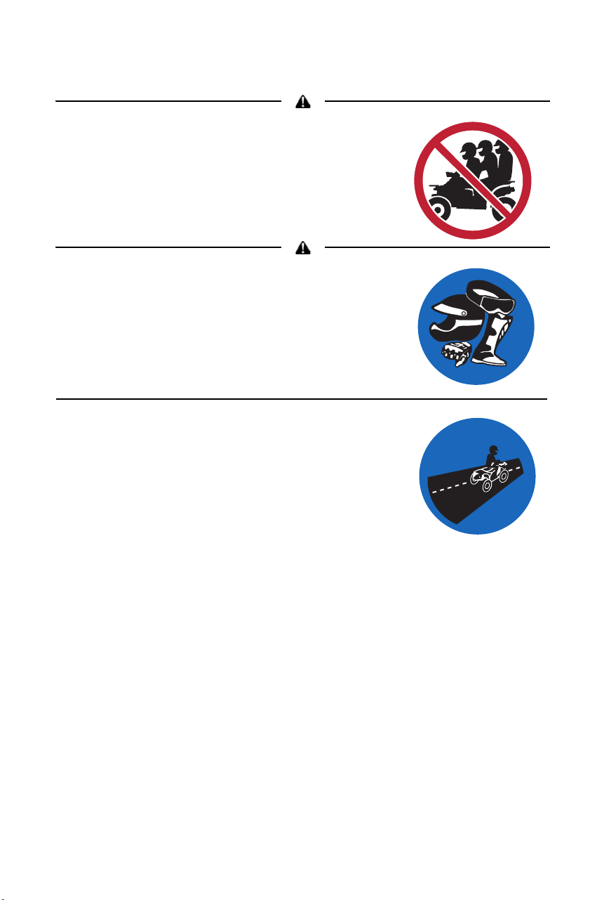
> Carrying a passenger
> Operating on steep inclines or sidehills
> Operating on paved surfaces
> Operating on slippery surfaces
> Operating on extremely rugged terrain or over obstacles
> Operating in deep or fast-flowing water
> Operating a damaged vehicle
WARNING
7
INTRODUCTION
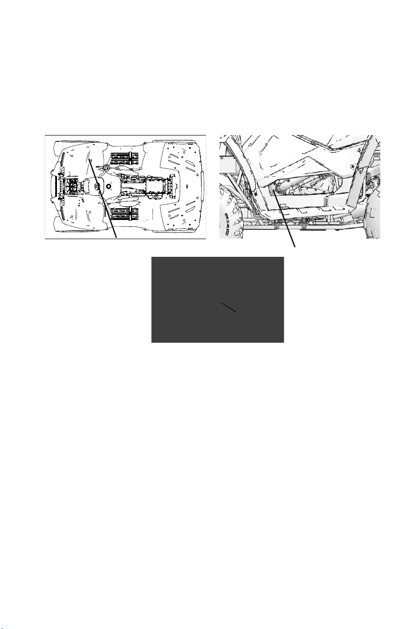
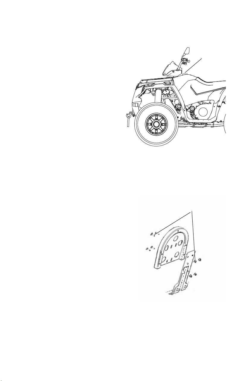
Vehicle Identification Numbers
Record your vehicle's identification numbers and key number in the
spaces provided. Remove the spare key and store it in a safe place. An
ignition key can be duplicated only by ordering a POLARIS key blank
(using your key number) and mating it with one of your existing keys.
The ignition switch must be replaced if all keys are lost.
Vehicle Model Number: ___________________________________________________
Frame VIN: _____________________________________________________________
Engine Serial Number: ____________________________________________________
Key Number: ___________________________________________________________
Key Number
Engine Serial
Number
VIN
(front, right-hand side
underneath rack)

8
SAFETY
Safety Training
Never operate this vehicle without proper instruction. Take a training
course.
For more information about safety, contact an authorized POLARIS
dealer or visit the POLARIS web site at www.polaris.com.
Read and understand your owner's manual, which includes valuable
information about all aspects of your vehicle, including safe operating
procedures.
Ride responsibly. Know all laws and regulations concerning the
operation of this vehicle in your area.
Age Restrictions
This vehicle is an ADULT VEHICLE ONLY. Operation is prohibited
for anyone under 16 years of age. Never allow anyone under 12 years of
age to ride as a passenger on a 2-up vehicle.
Equipment Modifications
The warranty on your POLARIS Tractor may be terminated if any
equipment has been added, or if any modifications have been made, that
increase speed or power. The addition of certain accessories, including
(but not limited to) mowers, blades, tires, sprayers and large racks may
change vehicle handling. Use only POLARIS-approved accessories.
Know their function and effect on the vehicle.
9
SAFETY
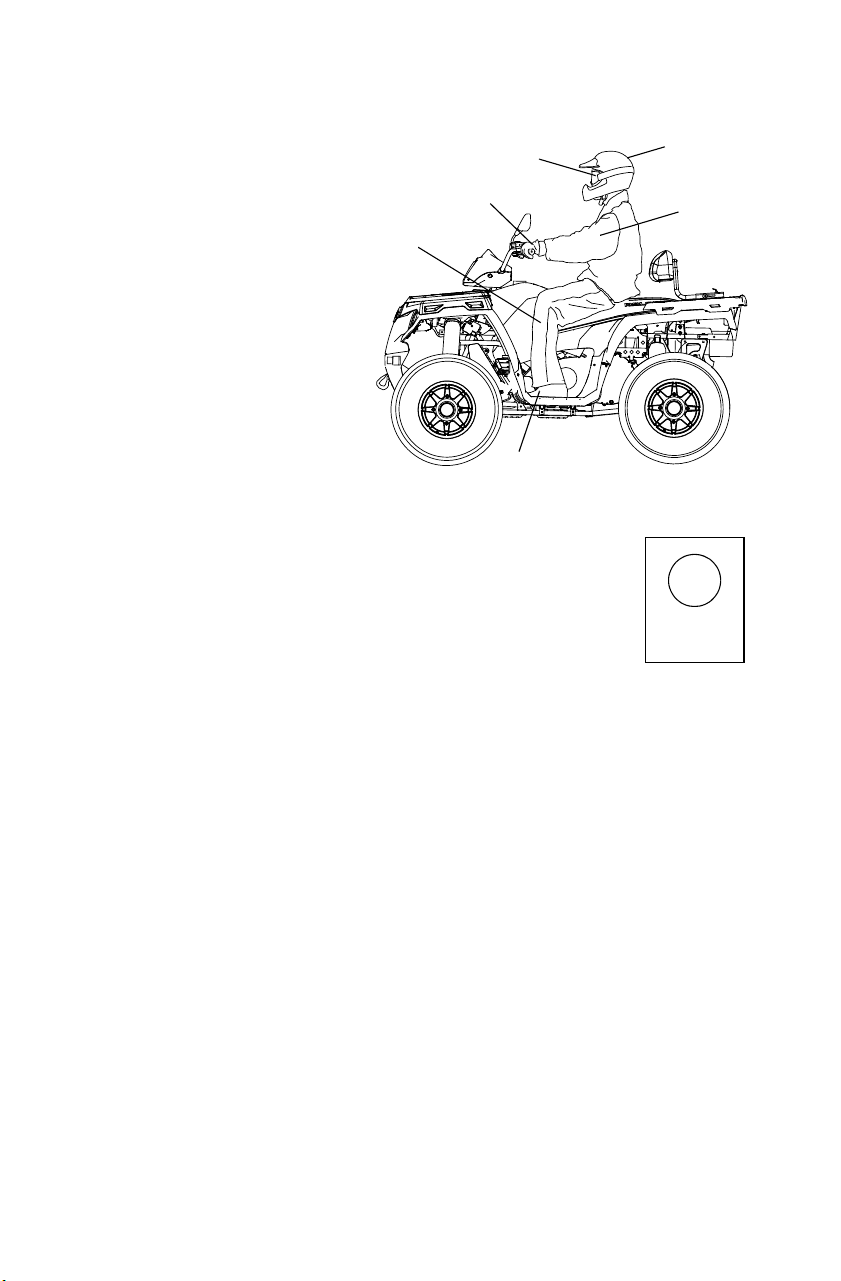
Safe Riding Gear
Always wear
protective clothing to
reduce the chance of
injury.
Helmet
Always wear a helmet
that meets or exceeds
established safety
standards.
Approved helmets in
the USA and Canada
bear a U.S. Department
of Transportation
(DOT) label.
Approved helmets in Europe, Asia and Oceania
bear the ECE 22.05 label. The ECE mark consists
of a circle surrounding the letter E, followed by the
distinguishing number of the country which has
granted approval. The approval number and serial
number will also be displayed on the label.
Eye Protection
Do not depend on eyeglasses or sunglasses for eye protection.
Whenever riding a POLARIS vehicle, always wear shatterproof goggles
or use a shatterproof helmet face shield. POLARIS recommends
wearing approved Personal Protective Equipment (PPE) bearing
markings such as VESC 8, V-8, Z87.1, or CE. Make sure protective eye
wear is kept clean.
Gloves
Off-road style gloves with knuckle pads are the best for comfort and
protection.
Boots
The best footwear is a pair of sturdy over-the-calf boots with low heels.
Clothing
Always wear long sleeves and long pants to protect arms and legs.
Riding pants with kneepads and a jersey with shoulder pads provide the
best protection.
Helmet
Eye Protection
Gloves
Boots
Long Pants
Long
Sleeves
E
4
051039
0006.31
10
SAFETY
Rider Safety
Serious injury or death can result if you do not follow the instructions and
procedures listed here and throughout this manual.
Read and understand all warnings, cautions and
operating procedures in this manual and on the safety
labels before operating the Tractor.
Never operate a Tractor without proper instruction.
Take a training course. Beginners should receive
training from a certified instructor. Contact an
authorized POLARIS Tractor dealer or visit the
POLARIS web site at www.polaris.com.
Never permit others to operate the Tractor unless
they have read and understand this manual and all
product labels, and have completed a certified safety training course.
Never allow anyone under 16 years of age to operate
this vehicle. Never allow anyone under 12 years of
age to ride as a passenger on a 2-up vehicle.
Engine exhaust contains poisonous carbon monoxide and can cause loss of
consciousness resulting in severe injury or death. Never run an engine in an
enclosed area.
WARNING
<
16
11
SAFETY
Rider Safety
Never carry more than one passenger on a
2-up vehicle. Do not carry a passenger on a
2-up vehicle until you have at least two
hours of driving experience with the vehicle.
See page 59.
Operator and any passenger must always wear
an approved helmet that fits properly and eye
protection (goggles or face shield), gloves,
boots, long sleeves and long pants.
This vehicle is approved for on-road use.
12
SAFETY
Rider Safety
Never consume alcohol or drugs before or
while operating a Tractor.
Always inspect your Tractor before each
use to verify that it's in safe operating
condition. Follow the inspection and
maintenance procedures outlined in this
manual. See page 54.
Keep both hands on the handlebars. Keep
both feet on the footrests. A passenger
should always be seated in the passenger
seat with both feet on the footrests and
both hands on the passenger grab
handles at all times.
Always travel slowly when operating on
unfamiliar terrain. Use extra caution.
Always follow the procedures outlined in
this manual for turning. See page 61.
Never turn sharply at excessive speeds,
which can lead to vehicle overturn.
13
SAFETY
Rider Safety
If a Tractor has been involved in an accident, always have an authorized
POLARIS dealer inspect the entire vehicle for possible damage, including (but
not limited to) brake, throttle and steering systems.
Never attempt jumps or other stunts.
Always follow the procedures outlined in this manual for driving on hills. See
page 62. Never operate on hills too steep for the Tractor or for your abilities.
Practice on smaller hills before attempting larger hills.
Always move the AWD switch to ADC AWD (if equipped) before ascending or
descending a hill. See page 37.
Never operate 570 or 450 HO models on hills steeper than 15°.
Never operate Touring models on hills steeper than 15°.
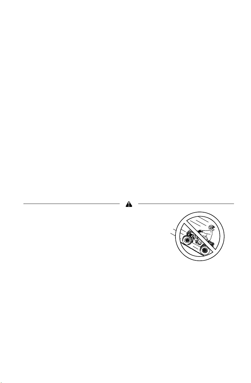
Always follow the procedures outlined in this
manual for driving downhill and for braking
on hills. See page 65.
Always move the AWD switch to ADC AWD
(if equipped) before ascending or
descending a hill. See page 37.
14
SAFETY
Rider Safety
Always follow the procedures outlined in this
manual for crossing the side of a hill. See
page 64.
Always move the AWD switch to ADC AWD
(if equipped) before ascending or
descending a hill. See page 37.
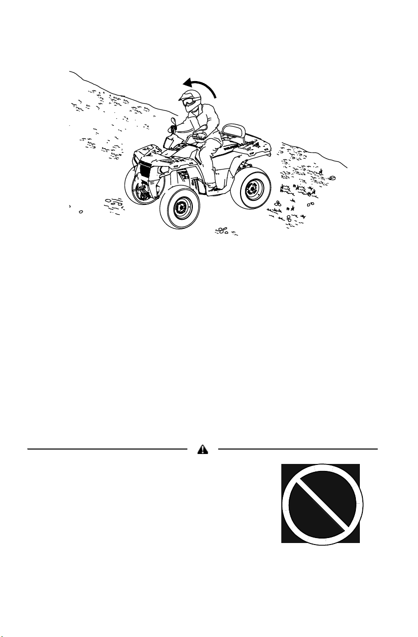
Never attempt to turn the Tractor around on
any hill until you've mastered (on level
ground) the turning technique outlined in this
manual.
Always follow the procedures outlined in this
manual for braking if you stall or roll
backwards while climbing a hill. Never back
down a hill. See page 66.
Always move the AWD switch to ADC AWD
(if equipped) before ascending or
descending a hill. See page 37.
Always follow the procedures outlined in this manual for operating over
obstacles. See page 70.
Always follow the procedures outlined in this manual for driving in reverse. See
page 71.
Never operate at excessive speeds. Travel
and turn at speeds appropriate for the terrain,
visibility, operating conditions, your skills and
a passenger’s skills.
15
SAFETY
Rider Safety
Always follow the procedures outlined in this
manual for operating on slippery or loose
surfaces. Use extra caution. Always avoid
skidding or sliding. See page 69.
Always follow the procedures outlined in this
manual for driving through water. Never drive
through deep or fast-flowing water. See page
68.
Always use the size and type of tires
specified for your vehicle. Maintain the
proper tire pressure.
16
SAFETY
Rider Safety
Never modify a Tractor through improper installation or use of accessories.
Never exceed the stated load capacity for your vehicle. Cargo must be properly
distributed and securely attached. Reduce speed and follow the instructions in
this manual for carrying cargo or towing. Allow a greater distance for braking.
Never operate the Tractor on a frozen body of water.
Operating on paved surfaces may affect
the handling and control of the Tractor and
could result in loss of control. Avoid
sudden turns or swift movement of the
handlebars.
Gasoline is highly flammable and explosive under certain conditions.
• Use extreme caution whenever handling gasoline.
• Refuel with the engine stopped. Refuel outdoors or in a well-ventilated area.
• Never fill a fuel container while it's on the vehicle. Static electricity between
the rack and container could cause a spark.
• Do not smoke or allow open flames or sparks in or near the area where
refueling is performed or where gasoline is stored.
• Do not overfill the tank. Do not fill the tank neck.
• If gasoline spills on your skin or clothing, immediately wash it off with soap
and water and change clothing.
17
SAFETY
Rider Safety
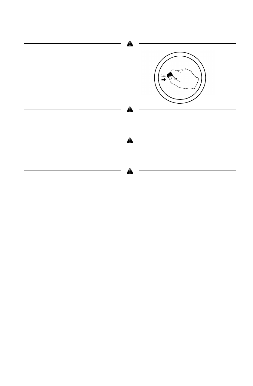
Always remove the ignition key when
the vehicle is not in use to prevent
unauthorized use or accidental
starting.
Hot components can cause serious burns and fire. Do not touch hot exhaust
system components. Always keep combustible materials away from the exhaust
system.
This vehicle is not equipped with an Occupant Protection Device capable of
protecting the operator from falling objects. Please be aware of your
surroundings at all times when operating this vehicle.
Avoid operating this vehicle when lightning could occur or near powerlines.
Rubber tires, rubber handgrips, and a foam seat will not protect a rider from
lightning strikes or electrical surges. Always seek safe shelter when lightning is
imminent and keep a safe distance from powerlines.
For more information about Tractor safety,
contact an authorized POLARIS Tractor dealer or visit
the POLARIS web site at www.polaris.com.
18
SAFETY
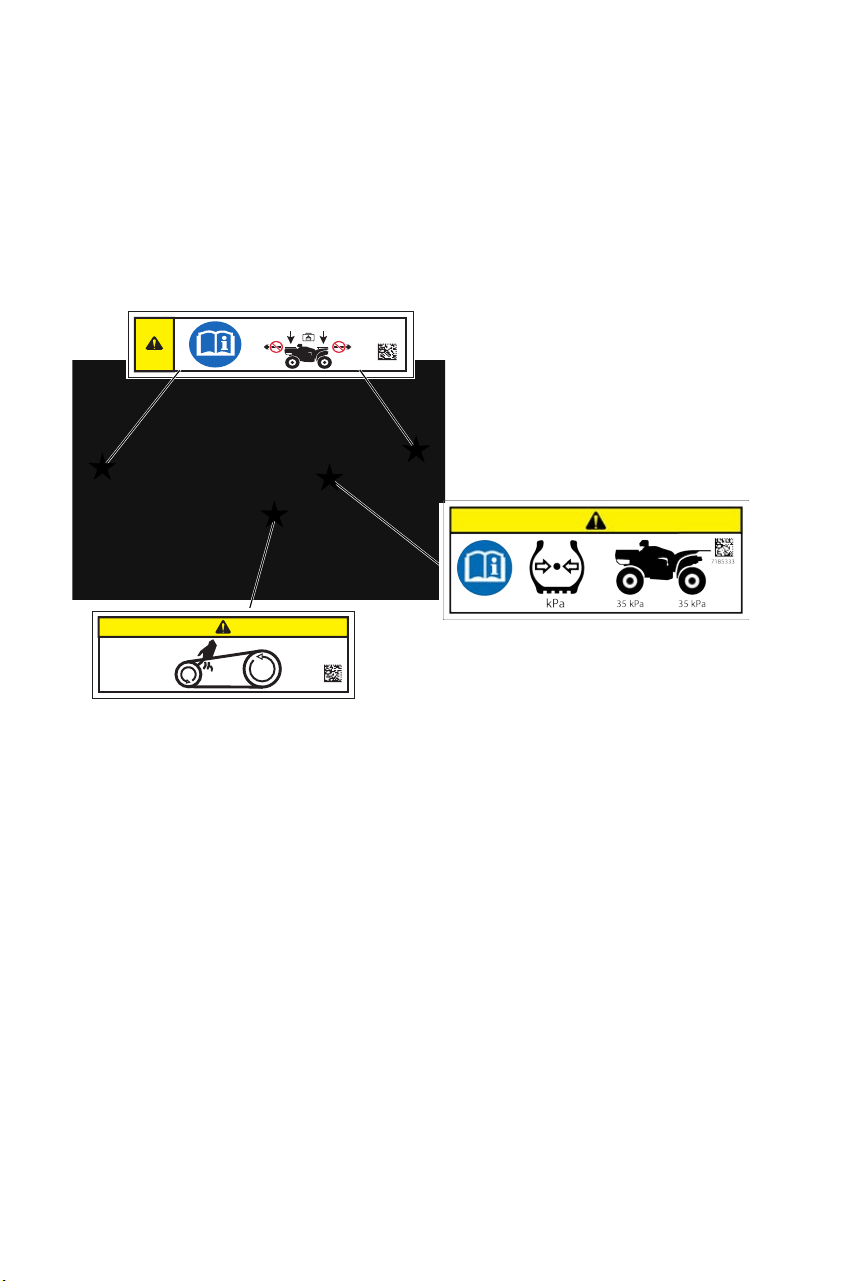
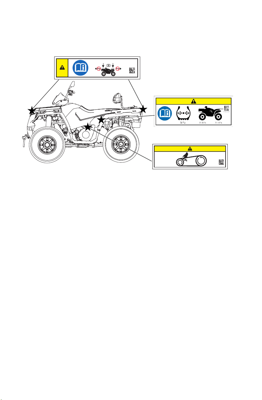
Safety Labels and Locations
Warning labels have been placed on the vehicle for your protection.
Read and follow the instructions on each label carefully. If a label
becomes illegible or comes off, contact your POLARIS dealer to
purchase a replacement. Replacement safety labels are provided by
POLARIS at no charge. The part number is printed on the label.
SPORTSMAN Touring 570 Labels
41 kg 82 kg
7181584
7181427
Clutch Cover Alert
Tire Pressure Alert
TIRE PRESSURE IN kPa: FRONT 35 REAR 35
Read Owner's Manual.
Clutch Cover Alert
Keep body parts away from belt.
Rack Alert
DO NOT TOW FROM RACK OR BUMPER. Vehicle damage or tipover may
result causing severe injury or death. Tow only from tow hooks or hitch.
Max. Rack Loads: Front 41 kg Rear 82 kg
Tire Pressure Alert
Rack Alert
19
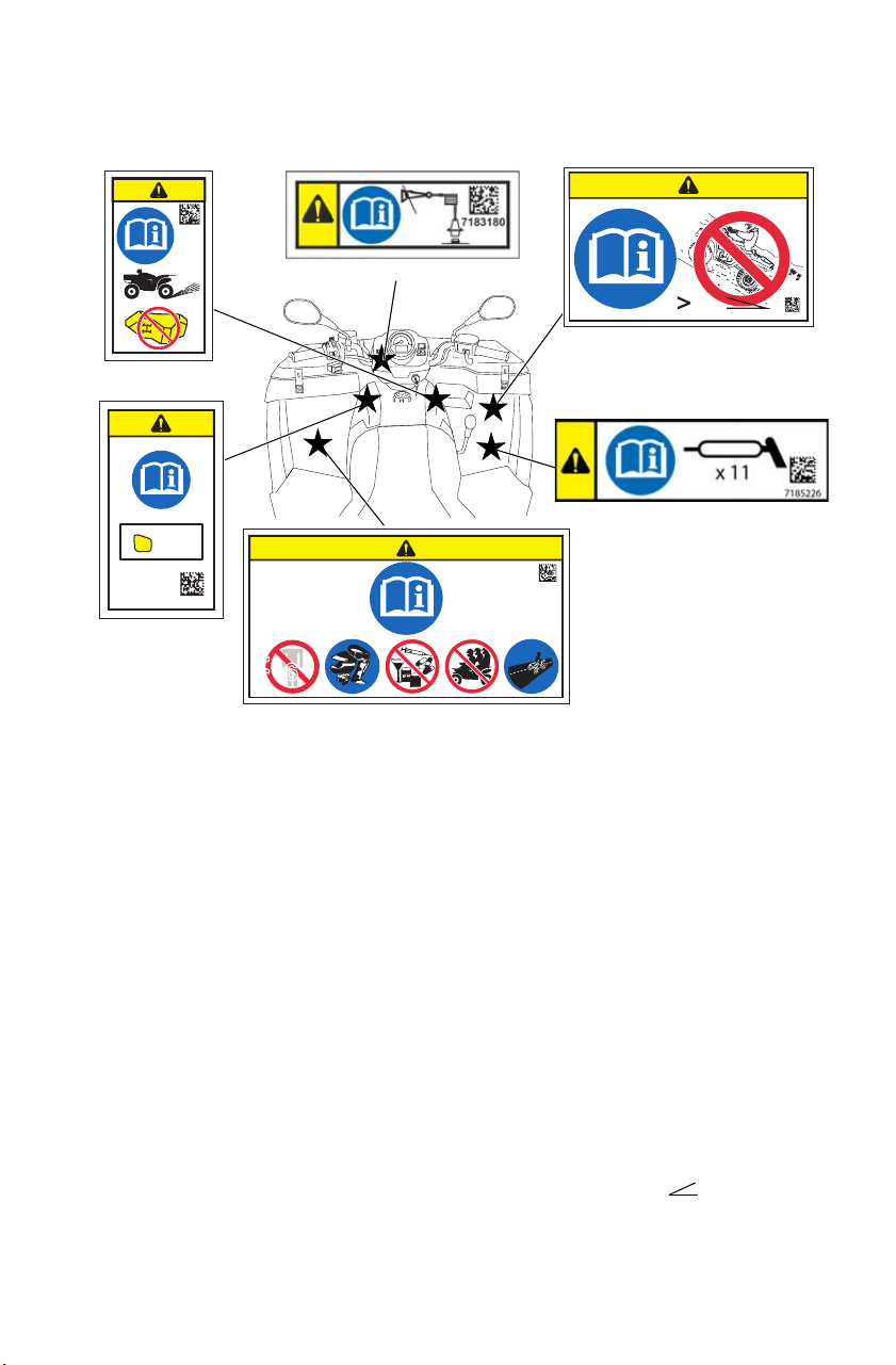
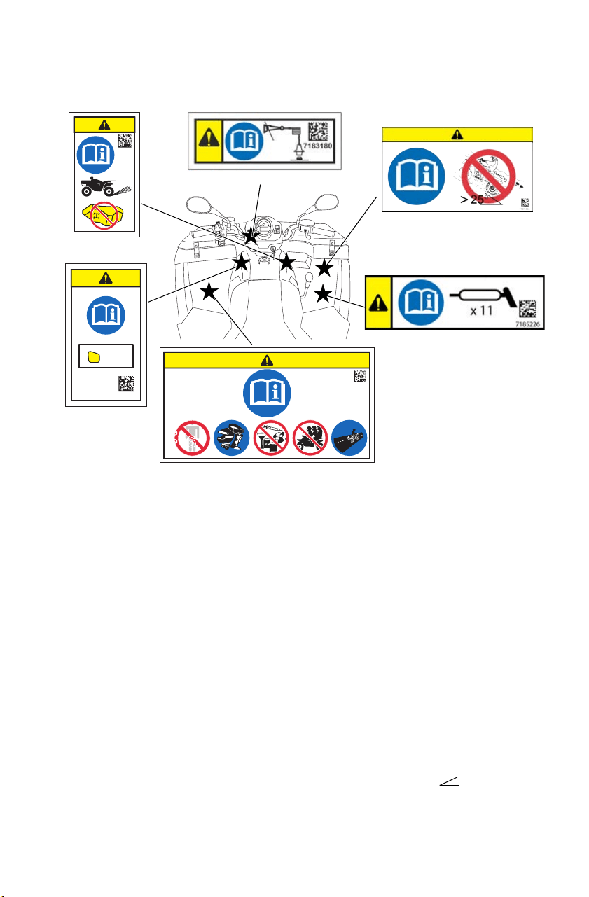
SAFETY
Safety Labels and Locations
SPORTSMAN Touring 570 Labels
Tether Switch Alert
Connect the tether switch before operating. Refer to page 29.
General Alert
Before you operate this vehicle, read the owner’s manual. Never allow anyone
under 16 years of age to operate this vehicle. Wear approved helmet, goggles,
and protective clothing. Never use alcohol or drugs before or while operating.
Never carry more than one passenger on this vehicle. This vehicle is approved
for on-road use.
Override Alert
Improper use of override button can lead to loss of control resulting in severe
injury or death. Do not activate override while throttle is engaged. Always apply
throttle gradually while in reverse.
AWD Alert
Do not push switch to engage AWD if the rear wheels are spinning. This may
cause severe drive shaft and clutch damage.
Hill Operation Alert
Never operate this vehicle on HILLS steeper than 15 degrees 15
°.
Greasing Points Alert
Lubricate as recommended.
7181543
15°
7181536
<
16
<
16
7181540
General Alert
Hill Operation Alert
Override
Alert
AWD Alert
Greasing Points Alert
SPEEDO
REVERSE
OVERRIDE
7181544
Tether Switch Alert
20
SAFETY
Safety Labels and Locations
SPORTSMAN 570/450 HO Labels
Tire Pressure Alert
TIRE PRESSURE IN kPa: FRONT 35 REAR 35.
Clutch Cover Alert
Keep body parts away from belt.
Rack Alert
DO NOT TOW FROM RACK OR BUMPER. Vehicle damage or tipover may
result causing severe injury or death. Tow only from tow hooks or hitch.
Max. Rack Loads: Front 41 kg Rear 82 kg
7181427
41 kg 82 kg
7181584
Clutch Cover Alert
Tire Pressure Alert
Rack Alert
21
SAFETY
Safety Labels and Locations
SPORTSMAN 570/450 HO Labels
Tether Switch Alert
Connect the tether switch before operating. Refer to page 29.
General Alert
Before you operate this vehicle, read the owner’s manual. Never allow anyone
under 16 years of age to operate this vehicle. Wear approved helmet, goggles,
and protective clothing. Never use alcohol or drugs before or while operating.
Never carry more than one passenger on this vehicle. This vehicle is approved
for on-road use.
Override Alert
Improper use of override button can lead to loss of control resulting in severe
injury or death. Do not activate override while throttle is engaged. Always apply
throttle gradually while in reverse.
AWD Alert
Do not push switch to engage AWD if the rear wheels are spinning. This may
cause severe drive shaft and clutch damage.
Hill Operation Alert
Never operate this vehicle on HILLS steeper than 15 degrees 15
°.
Greasing Points Alert
Lubricate as recommended.
7181543
<
16
<
16
7181540
General Alert
Hill Operation Alert
Override
Alert
AWD Alert
Greasing Points Alert
SPEEDO
REVERSE
OVERRIDE
7181544
Tether Switch Alert
22
SAFETY
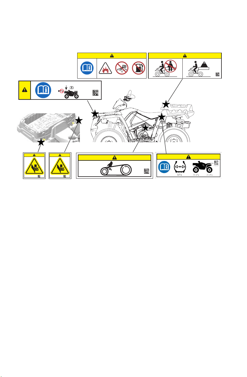
Safety Labels and Locations
SPORTSMAN X2 Labels
Rack Alert
DO NOT TOW FROM RACK OR BUMPER. Vehicle damage or tipover may
result causing severe injury or death. Tow only from tow hooks or hitch.
Max. Rack Load: Front 41 kg
Box Alert
Remove flammable material containers from box before filling. Passengers can
be thrown off. This can cause serious injury or death. Never carry passengers in
cargo box. Maximum Box Load: 181 kg
Crush Alerts
To prevent a crushing injury to hands and fingers, keep hands and fingers away
from the lower front edge of the cargo box while lowering the box.
Tire Pressure Alert
TIRE PRESSURE IN kPa: FRONT 35 REAR 35
Clutch Cover Alert
Keep body parts away from belt.
41 kg
7182351
7182312
< 181 kg
7181427
Clutch Cover Alert
Tire Pressure Alert
Rack Alert
Box Alert (inside box)
7184130
Crush Alerts
7184130

23
SAFETY
Safety Labels and Locations
SPORTSMAN X2 Labels
Tether Switch Alert
Connect the tether switch before operating. Refer to page 29.
General Alert
Before you operate this vehicle, read the owner’s manual. Never allow anyone
under 16 years of age to operate this vehicle. Wear approved helmet, goggles,
and protective clothing. Never use alcohol or drugs before or while operating.
Never carry more than one passenger on this vehicle. This vehicle is approved
for on-road use.
Override Alert
Improper use of override button can lead to loss of control resulting in severe
injury or death. Do not activate override while throttle is engaged. Always apply
throttle gradually while in reverse.
AWD Alert
Do not push switch to engage AWD if the rear wheels are spinning. This may
cause severe drive shaft and clutch damage.
Hill Operation Alert
Never operate this vehicle on HILLS steeper than 15 degrees 15
°.
Greasing Points Alert
Lubricate as recommended.
7181543
15°
7181536
<
16
<
16
7181540
General Alert
Hill Operation Alert
Override
Alert
AWD Alert
Greasing Points Alert
SPEEDO
REVERSE
OVERRIDE
7181544
Tether Switch Alert

24
FEATURES AND CONTROLS
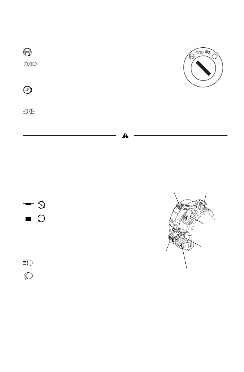
Switches
Momentary High Beam Switch
Press this switch with your left forefinger to activate the headlight high
beam. The lights will return to low beam when the switch is released.
Winch Switch
See page 78 for winch information.
Mode/Reverse Override Switch
Press the switch to toggle through the speedometer display modes
(except in reverse). See page 38. To gain additional power while
operating in reverse, press the override switch before opening the
throttle. This will cancel the reverse speed limit function.
The reverse override switch also acts as a MODE switch when held
down for approximately one half second. See the instrument cluster
information beginning on page 38.
Tip: The override switch will not function as a MODE switch if the transmission
is in reverse.
Activating the override switch while the throttle is open can cause loss of control.
Do not activate the override switch while the throttle is open.
Mode/Reverse
Override Switch
Main Key
Switch
AWD Switch
Winch Switch
Momentary High-Beam
Switch
Work Light
Switch
25
FEATURES AND CONTROLS
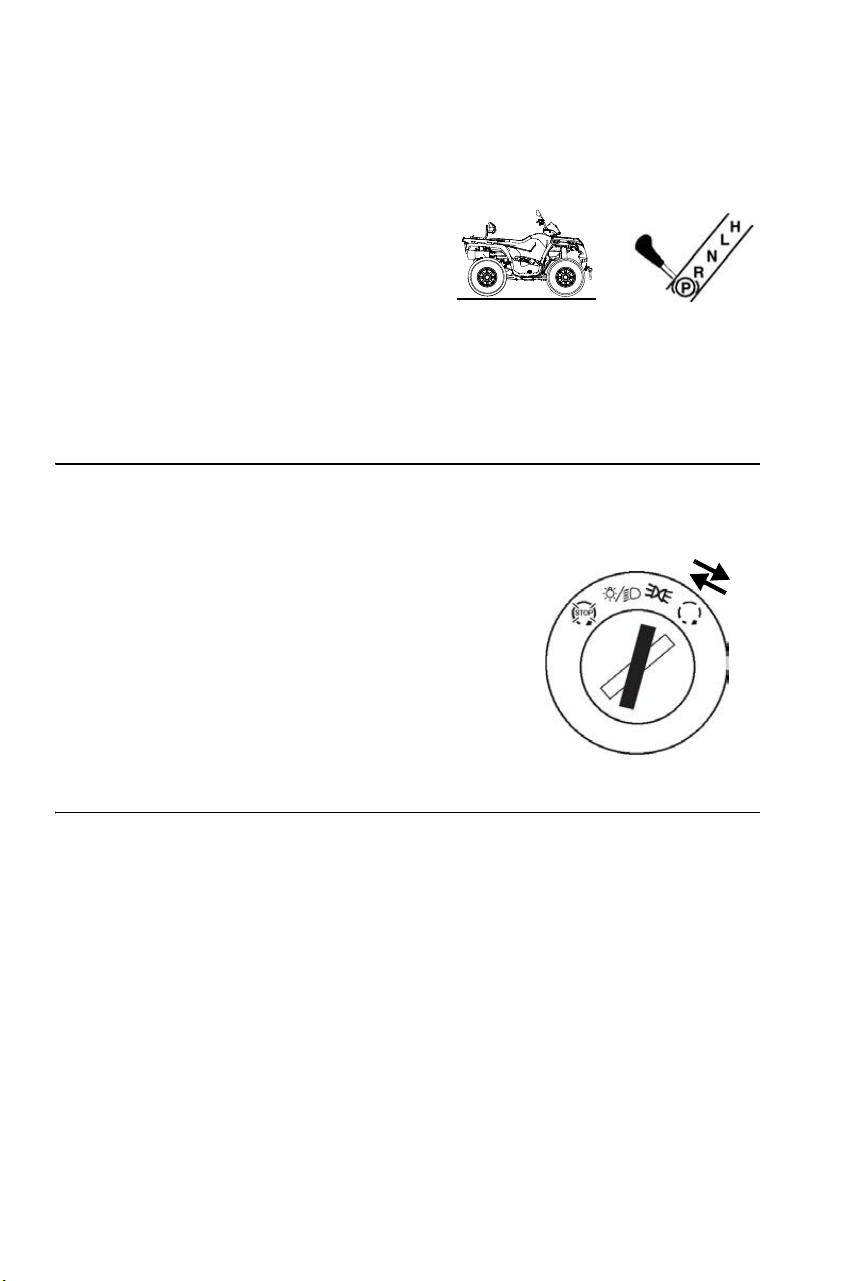
Switches
Main Key Switch
End all electrical power to the vehicle.
The LIGHTS ON position turns the headlights
on. The engine stop switch must be in the RUN
position.
Start the engine. The headlights are not on in
this position.
After starting the engine, release the key switch to the PARKING
LIGHTS ON position. The parking lights and taillights are on in
this position.
Do not attach a large key fob or key ring to the main switch. It may contact the
gas tank cap when turning, causing an interruption to the electrical system and
an unexpected engine shut-down during operation. This could result in serious
injury or death.
Engine Stop Switch
The engine will not start or run when the
switch is in the OFF position.
OFF (STOP)
RUN
Light Switch (High/Low Beam)
Use the light switch to change the
headlights from high beam to low beam.
High Beam
Low Beam
Override
Switch
Engine
Stop
Switch
Light
Switch
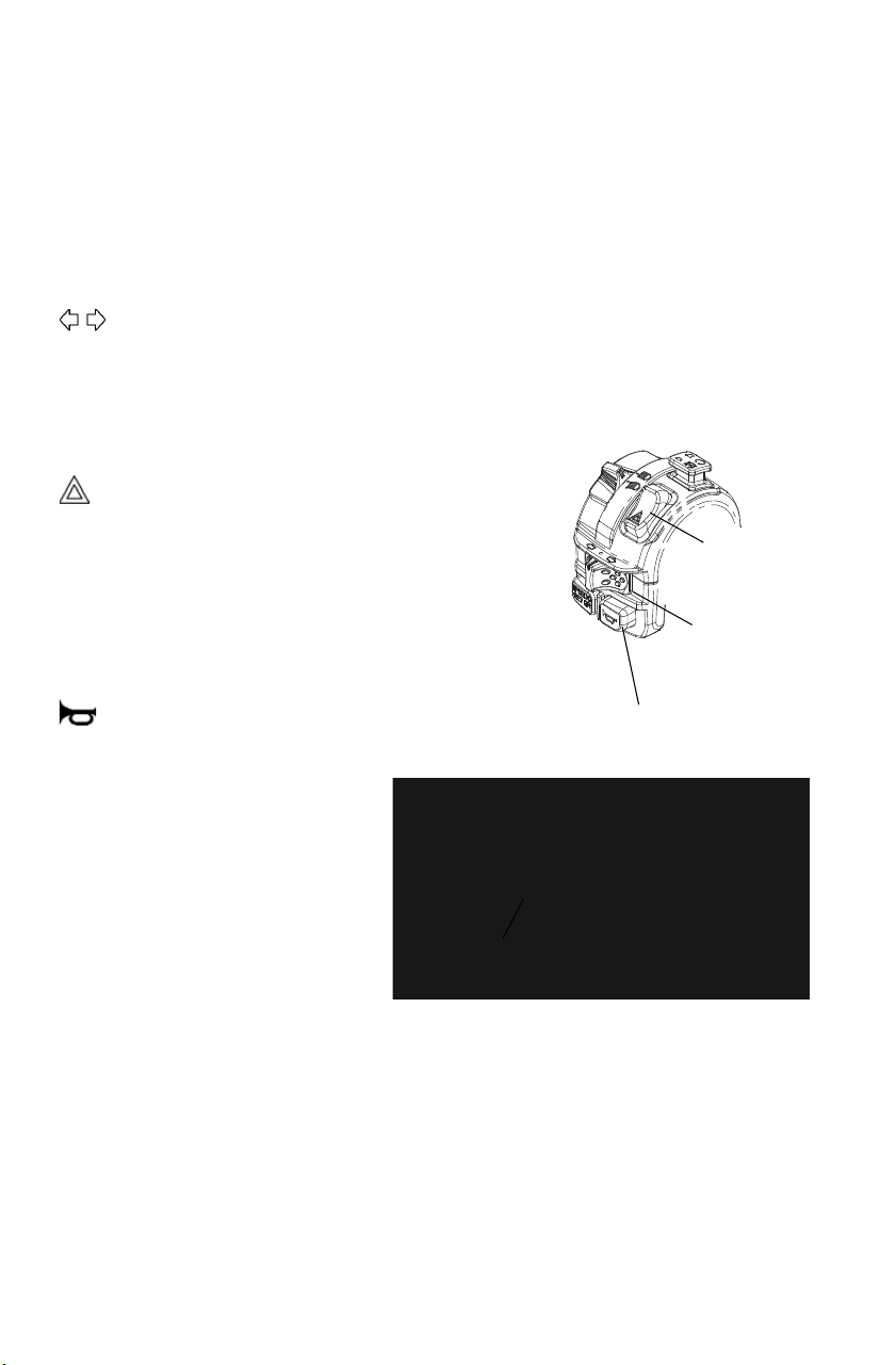
Horn
Switch
Hazard
Switch
Turn
Signal
Switch
26
FEATURES AND CONTROLS
Switches
Work Light Switch
The work light switch controls a light located in the pod. Use the light
when additional light is needed at the front of the vehicle, but turn the
work light off when driving the vehicle (on-road).
Turn Signal Switch
Push the toggle switch either left or right to activate the
corresponding turn signal light. The indicator in the gauge will also
flash. Return the toggle to the center position and push it inward to end
the signal.
Hazard Warning Switch
Push the hazard warning switch
to cause all turn signal lights to
flash simultaneously. Use this
feature to alert others of an
emergency or other situation
requiring caution.
Horn Switch
Press the horn switch to sound
the horn.
AWD Switch
Use the AWD switch to
engage ADC AWD (if
equipped), AWD or 2X4. See
page 35. The vehicle
automatically engages AWD
when operating in reverse if
the AWD switch is set to
either AWD position.
Horn
Switch
Hazard
Switch
Turn
Signal
Switch
AWD
Switch

27
FEATURES AND CONTROLS
Mirrors
Use the mirrors to assist in traffic maneuvers. Always check and adjust
the mirrors before driving the Tractor.
Throttle Lever
Failure to check or maintain proper operation of the throttle system can result in
an accident if the throttle lever sticks during operation. Check the lever for
proper operation before starting the engine. Check occasionally during
operation.
Do not start or operate a Tractor with sticking or improperly operating throttle
controls. Contact your dealer for repair if throttle problems arise.
Press the throttle lever to increase
engine speed and vehicle movement.
Release the lever to reduce engine
speed and vehicle movement.
28
FEATURES AND CONTROLS
Brakes
Aggressively applying the brakes when backing down a hill may cause rear
tipover. Aggressively applying the brakes while moving forward may cause the
rear wheels to skid and result in loss of control. Read this owner's manual and
understand the operation of all brake systems on this vehicle. Always use
caution whenever applying the brakes.
Foot Brake
The all-wheel foot brake is located on the
right footrest. The foot brake operates both
front and rear brakes. Press the brake pedal
down with your foot to apply the all-wheel
brakes. If the rear wheels begin to skid or
slide while using the foot brake, reduce
brake pressure.
Hand Brake Lever
The hand brake operates both front and rear
brakes. Squeeze the brake lever toward the
handlebar to apply the all-wheel brakes. If
the rear wheels begin to skid or slide while
using the brake, reduce lever pressure.
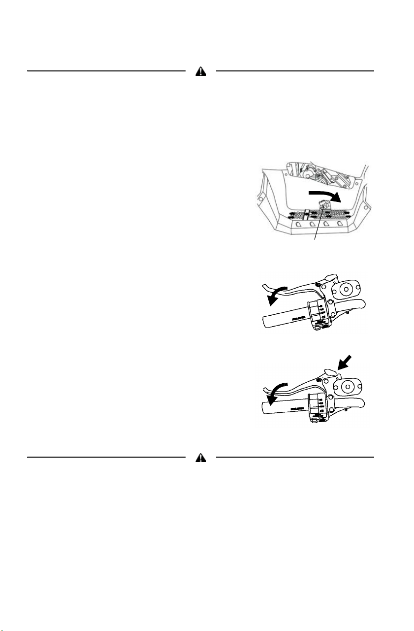
Parking Brake
1. Place the transmission in PARK.
2. Squeeze the brake lever toward the
handlebar. Push the parking brake lock
forward to engage the lock. Release the
brake lever.
3. To release the parking brake lock,
squeeze and release the brake lever.
Operating the vehicle while the parking brake is engaged could result in an
accident and serious injury or death. Always release the parking brake lock
before operating.
Foot Brake

29
FEATURES AND CONTROLS
Operator Presence Detection
This vehicle is equipped with a feature that detects operator presence on
the vehicle. If the system does not detect operator presence under certain
conditions, an alert will sound and the rider information center will
display “Shift to Park”.
Disconnecting the tether switch will NOT stop a running engine. The purpose of
the tether switch connection is to help ensure that an operator is on board and in
control of the vehicle while the engine is running.
The alert and display message will occur if the tether switch is not
connected and if the transmission is not set to PARK (P).
The message
and buzzing will cease after 10 seconds.
Electronic Power Steering (EPS)
Electronic power steering (EPS), if equipped, engages when the ignition
key is turned to the ON position. EPS remains engaged whether the
vehicle is moving or idle. See page 39 for EPS Warning Indicator
information.
30
FEATURES AND CONTROLS
Fuel Tank Cap
This vehicle is equipped with a
digital fuel gauge that will indicate
a low fuel condition. Refuel when
the gauge indicates a low fuel
condition.
Always refuel with the engine
stopped, and outdoors or in a well
ventilated area. Refuel on a level
surface.
Remove the fuel tank cap to add
fuel to the fuel tank. Use either
leaded or unleaded gasoline with a
minimum pump octane number of
87 = (R + M/2) octane. Do not use
fuel with ethanol content greater
than 10 percent, such as E-85 fuel.
Passenger Seat Backrest (Touring)
The passenger backrest can be adjusted vertically.
1. Unzip the two zippers at the bottom
of the backrest pad. Lift the pad
upward to remove it from the
backrest frame.
2. To adjust the backrest upward or
downward, loosen the four vertical
adjustment screws on the front side
of the backrest frame. Slide the
backrest upward or downward to the
desired position and tighten the
screws.
3. Reinstall the backrest pad.
Fuel Tank
Cap
Vertical Adjustment
Screws

31
FEATURES AND CONTROLS
Seat
Seat Removal
1. Grasp one side of the seat
near the rear edge.
2. Pull upward abruptly to
disengage the under-seat
fasteners.
3. Remove the seat.
Extreme Use Battery
An optional extreme use battery may be available for your model. If the
performance of the factory-installed battery is inadequate due to
operation in extreme cold or due to extended use of multiple electrical
accessories, please see your POLARIS dealer. Ask your dealer to
provide any installation procedures that may differ for an extreme use
battery.
32
FEATURES AND CONTROLS
Hitches
See page 146 for hitch weight capacities.
Do not operate a combination Tractor-machine or Tractor-trailer unless all
instructions have been followed. See pages 72-77.
Whenever the Tractor is towing, always stay clear of the area between the
Tractor and the towed object.
Rear Hitch
Use the rear hitch for towing a trailer. See pages 72-77 for procedures.
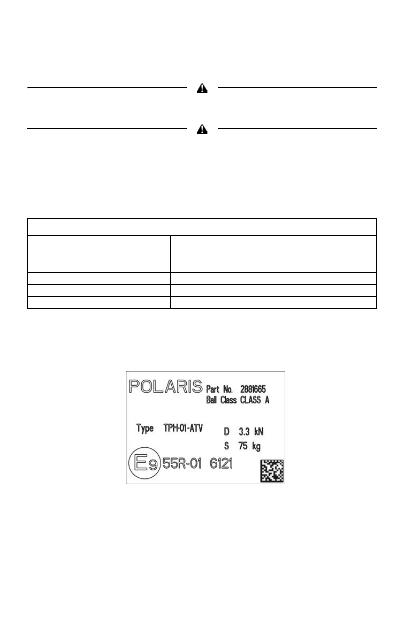
Rear Hitch Certification Label
The hitch certification label is located near the hitch on models
equipped with factory-installed rear hitch.
Rear Hitch Specifications
Material S355J2+N
Fasteners Metal pin with security cotter pin
Weld Length and Positions 4 mm fillet, all around
Maximum Vertical Load 75 kg (on coupling point)
Maximum Towable Mass 830 kg
Approval # E9-55R01-6121

33
FEATURES AND CONTROLS
Hitches
Hitch Installation/Removal
1. To remove the hitch, remove the cotter pin and hitch pin. Remove
the hitch from the receiver, then reinstall the hitch pin and secure the
cotter pin to the hitch.
2. To install the hitch, remove the cotter pin from the hitch pin and
remove the hitch pin.
3. Install the hitch to the receiver.
4. Reinstall the hitch pin (from the left side of the hitch) through the
bore of both the receiver and the hitch.
Reinstall the cotter pin. Make sure the hitch assembly is secure at that
the cotter pin is properly engaged over the hitch pin.
Cotter Pin
Hitch Pin

34
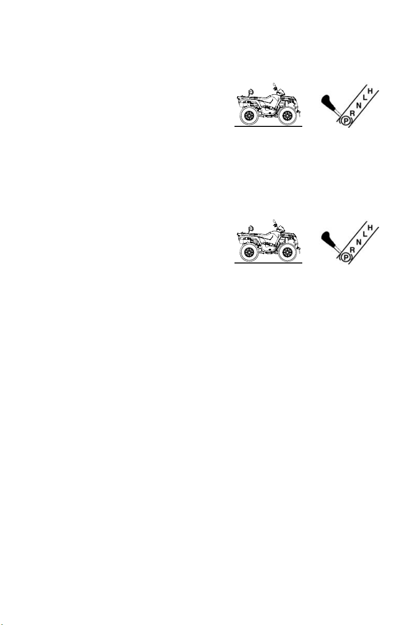
FEATURES AND CONTROLS
Automatic Transmission Gear Selector
The transmission gear selector is located on
the right side of the vehicle.
H: High Gear
L: Low Gear
N: Neutral
R: Reverse
(P):Park
Whenever the vehicle is left unattended,
always place the transmission in PARK. The
transmission is locked when it’s in PARK.
NOTICE: Shifting gears with the engine speed
above idle or while the vehicle is moving
can cause transmission damage.
Belt Life
To extend belt life, use LOW forward gear when pulling a heavy load at
less than 11 km/h for extended periods and when operating uphill at a
slow speed.
Gear
Selector

35
FEATURES AND CONTROLS
All Wheel Drive (4X4) System
The All Wheel Drive system
is controlled by the AWD
momentary switch.
Engage AWD before getting
into conditions where front
wheel drive may be needed.
If the rear wheels are
spinning, release the throttle
before switching to AWD.
• Move the momentary
switch to the right to
engage AWD.
• Move the momentary switch to the right, past the AWD setting, to
engage ADC AWD (if equipped).
• Move the momentary switch to the far left to operate in two-wheel
drive (2X4).
NOTICE: Switching to AWD or ADC AWD (if equipped) while the rear wheels
are spinning may cause severe drive shaft and gearcase damage.
Always switch to AWD or ADC AWD (if equipped) while the rear
wheels have traction or are at rest.
AWD
Switch

36
FEATURES AND CONTROLS
All Wheel Drive (4X4) System
AWD Mode
Move the momentary switch to the right to engage AWD (4X4). AWD
will engage when engine speed slows to below 3100 RPM. The gauge
will display “AWD”.
There is no limit to the length of time the vehicle may remain in AWD.
The vehicle automatically engages AWD when operating in reverse if
the switch is set to the AWD position.
Once enabled, AWD remains enabled until the switch is turned off. If
the switch is turned off while the demand drive unit is moving, it will
not disengage until the rear wheels regain traction.
When in AWD, the demand drive unit will automatically engage any
time the rear wheels lose traction. When the rear wheels regain traction,
the demand drive unit will automatically disengage.
ADC AWD Mode (if equipped)
Move the momentary switch to the right, past the AWD setting, to
engage ADC AWD (if equipped). When the switch is on ADC AWD,
the ADC system allows engine braking to all four wheels when the
vehicle descends a hill or incline. Always move the AWD switch to
ADC AWD before ascending or descending a hill. See page 37.
2X4 Mode
Move the momentary switch to the far left to operate in two-wheel drive
(2X4). AWD will disengage when engine speed slows to below 3100
RPM. The gauge will display “2X4”.
TURF Mode (X2 Models)
When operating in TURF mode, the inside rear wheel will rotate
independently from the outside during turns. Operate in TURF mode
only as neede to protect smooth, level surfaces from tire damage. DO
NOT operate in TURF mode when climbing or descending hills, when
sidehilling, or when operating on uneven, loose, or slippery terrain such
as sand, gravel, ice, snow, obstacles, and water crossings. Always
operate in ADC 4X4 or 4X4 on these types of terrain.
WARNING! Operating in TURF mode when on sloped, uneven, or loose terrain
could cause loss of control and result in serious injury or death. One rear wheel
may slip and lose traction or may lift up and grab when it touches the ground
again.

37
FEATURES AND CONTROLS
Active Descent Control (ADC) System
The ADC system allows engine braking to all four wheels when the
vehicle descends a hill or incline. Always move the AWD switch to
ADC AWD before ascending or descending a hill.
Engaging Active Descent Control
The ADC system will automatically engage when all four of the
following conditions occur:
• The AWD switch must be in the ADC AWD position
• Vehicle speed must be 15 mph (25 km/h) or less
• The throttle must be closed (throttle lever released)
• The transmission must be in gear (high, low or reverse)
Disengaging Active Descent Control
The ADC system will automatically disengage if at least one of the
following conditions occur:
• The AWD switch is moved out of the ADC AWD position
• Vehicle speed exceeds 15 mph (25 km/h)
• The throttle is open (throttle is applied)
• The transmission is shifted to neutral or park

38
FEATURES AND CONTROLS
Instrument Cluster
NOTICE: High water pressure may damage ATV components. Wash the ATV
by hand or with a garden hose using mild soap.
Certain products, including insect repellents and chemicals, will
damage the speedometer lens and other plastic surfaces. Do not use
alcohol to clean the instrument cluster. Do not allow insect sprays to
contact the lens. Immediately clean off any gasoline that splashes on
the instrument cluster.
Digital/Analog Gauge
Speedometer
The speedometer displays vehicle speed in either miles per hour (MPH)
or kilometers per hour (km/h).
Rider Information
Center
Speedometer
Indicator Lamps
39
FEATURES AND CONTROLS
Instrument Cluster
Digital/Analog Gauge
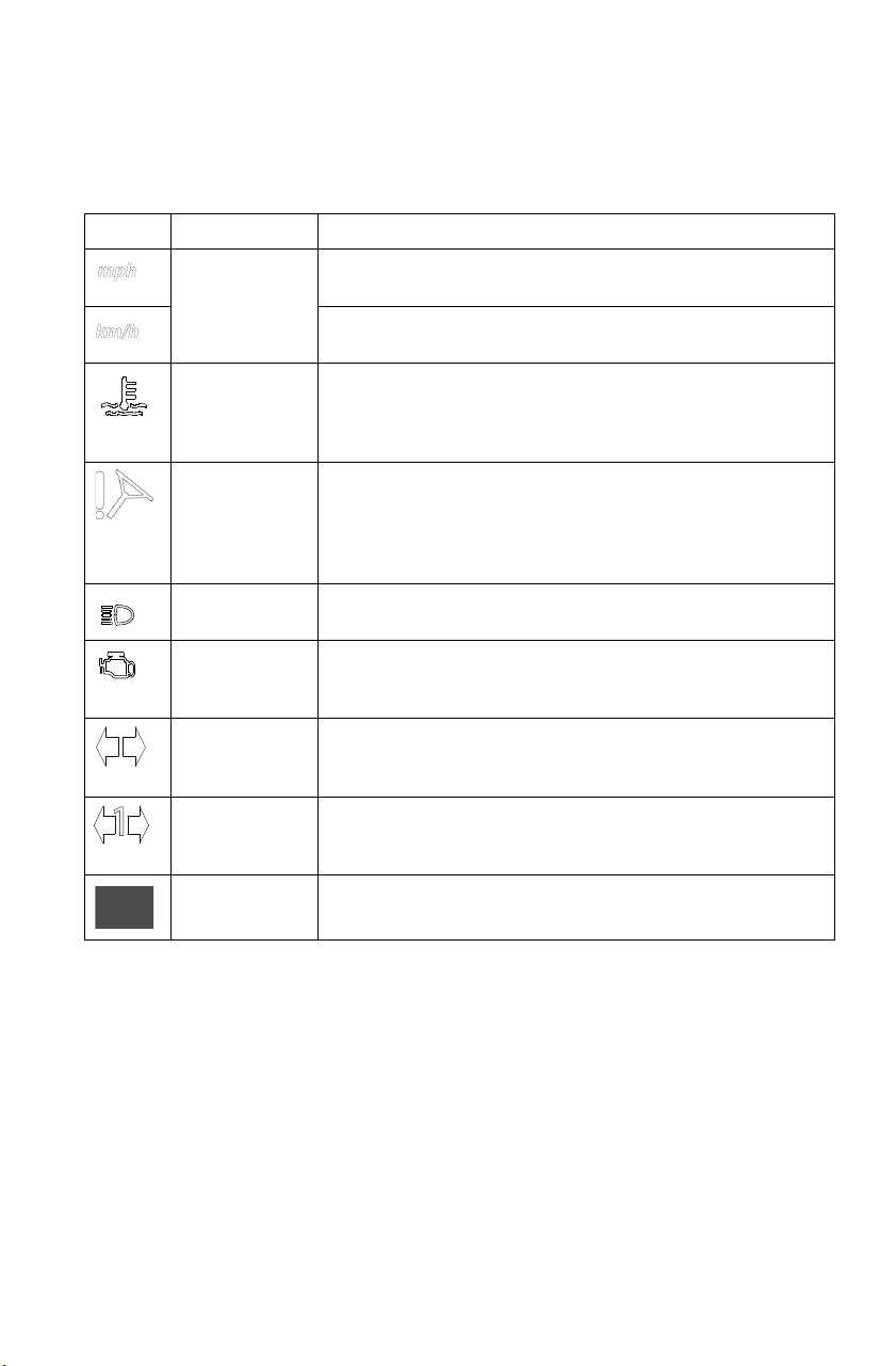
Indicator Lamps
Lamp Indicates Condition
Vehicle
Speed
When standard mode is selected, speed displays in
miles per hour.
When metric mode is selected, speed displays in
kilometers per hour.
Over
Temperature
This lamp flashes to indicate an overheated engine. If
the indicator stops flashing but remains illuminated,
the overheating condition remains, and the system
will automatically reduce engine power.
EPS Warning
(if equipped)
This indicator illuminates when the key is turned to
the ON position and goes off when the engine is
started. If the light remains on after starting the
engine, the EPS system is inoperative. See your
authorized POLARIS dealer for service.
High Beam This lamp illuminates when the headlamp switch is
set to high beam.
Check Engine This indicator appears if an EFI-related fault occurs.
Do not operate the ATV if this warning appears.
Serious engine damage could result. See your dealer.
Turn Signal The corresponding turn signal indicator flashes when
the left, right or both turn signals (hazard warning) are
active.
Trailer Turn
Signal
The corresponding turn signal indicator flashes when
the trailer light harness is properly connected to the
vehicle and a left or right turn signal is active.
Brake Failure This icon will illuminate if the vehicle sensors detect a
malfunction in the brake system.

40
FEATURES AND CONTROLS
Instrument Cluster
NOTICE: High water pressure may damage ATV components. Wash the ATV
by hand or with a garden hose using mild soap.
Certain products, including insect repellents and chemicals, will
damage the speedometer lens and other plastic surfaces. Do not use
alcohol to clean the instrument cluster. Do not allow insect sprays to
contact the lens. Immediately clean off any gasoline that splashes on
the instrument cluster.
Digital/Analog Gauge (Premium Models)
Speedometer
The speedometer displays vehicle speed in either miles per hour (MPH)
or kilometers per hour (km/h).
Fuel Gauge
Gear Indicator
Indicator Lamps
Clock
41
FEATURES AND CONTROLS
Instrument Cluster
Digital/Analog Gauge (Premium Models)
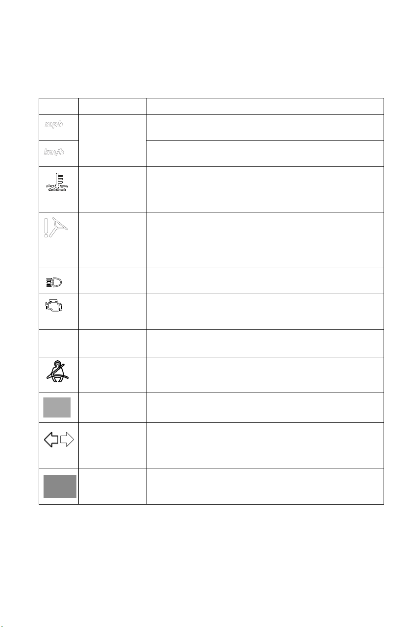
Indicator Lamps
Lamp Indicates Condition
Vehicle
Speed
When standard mode is selected, speed displays in
miles per hour.
When metric mode is selected, speed displays in
kilometers per hour.
Over
Temperature
This lamp flashes to indicate an overheated engine. If
the indicator stops flashing but remains illuminated,
the overheating condition remains, and the system
will automatically reduce engine power.
EPS Warning
(if equipped)
This indicator illuminates when the key is turned to
the ON position and goes off when the engine is
started. If the light remains on after starting the
engine, the EPS system is inoperative. See your
authorized POLARIS dealer for service.
High Beam This lamp illuminates when the headlamp switch is
set to high beam.
Check Engine This indicator appears if an EFI-related fault occurs.
Do not operate the ATV if this warning appears.
Serious engine damage could result. See your dealer.
MODE Button Press the mode button to toggle between different
displays on the digital gauge.
Seat Belt This lamp flashes for several seconds when the key is
turned to the ON position. The lamp is a reminder to
wear helmet and seat belt before operating.
Brake Failure This icon will illuminate if the vehicle sensors detect a
malfunction in the brake system.
Turn Signals/
Hazard
Signals
Both arrows flash when either a turn signal or the
hazard signal is activated. If a lamp fails, or if there is
a short circuit in the signal system, the lamp flashes at
more than twice the normal rate.
Trailer Turn
Signal
The corresponding turn signal indicator flashes when
the trailer light harness is properly connected to the
vehicle and a left or right turn signal is active.
MODE
42
FEATURES AND CONTROLS
Instrument Cluster
Digital/Analog Gauge
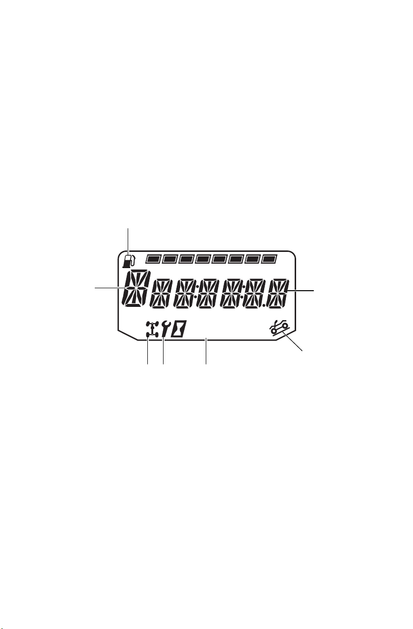
Rider Information Center
The rider information center is located in the instrument cluster. All
segments will light up for one second at start-up. If the instrument
cluster fails to illuminate, a battery over-voltage may have occurred and
the instrument cluster may have shut off to protect the electronic
speedometer. If this occurs, take the ATV to your POLARIS dealer for
proper diagnosis.
The information center is set to display standard units of measurement
and a 12-hour clock at the factory. To change to metric and/or a 24-hour
clock, see page 45.
Trip 1
km
mi
RPM
EF
88
:
88
1
2
3
5
67
4

43
FEATURES AND CONTROLS
Instrument Cluster
Digital/Analog Gauge
Rider Information Center
1. Gear Display - This area displays gear shifter position:
H = High Gear
L = Low Gear
N = Neutral
R = Reverse Gear
P = Park
-- = Gear Signal Error (or shifter between gears)
2. Fuel Gauge Display - The segments of the fuel gauge show the
level of fuel in the fuel tank. When the last segment clears, a low
fuel warning is activated. All segments including the fuel icon will
flash. Refuel immediately.
Tip: If the fuel icon fails to display, an open or short circuit has occurred in the
fuel sensor circuit. See your dealer.
3. Information Display - This area displays odometer, trip meter,
engine hour meter, engine speed and programmable service hour
interval.
4. Active Descent Control Display (if equipped) - This icon displays
when ADC is active. See page 37.
5. Clock Display - The clock displays time in a 12-hour or 24-hour
format. If the engine is turned off, press the MODE button. The
time will display for 5-10 seconds. See page 45 for resetting
instructions.
6. Service Reminder Display - A flashing wrench symbol alerts the
operator that the preset service interval has been reached. The
vehicle should be brought to your dealer for scheduled
maintenance. See page 45 for resetting instructions.
7. AWD Display - This icon displays when the AWD system is
engaged (switch is on either ADC AWD or AWD).

44
FEATURES AND CONTROLS
Instrument Cluster
Digital/Analog Gauge
Rider Information Center
The reverse override button acts as the MODE button when pressed and
released quickly. The transmission cannot be in reverse when using the
override button as a MODE button. This feature does not contain a
vehicle speed lockout function and can be used at any operating speed.
Display Units (Standard/Metric)
The display can be changed to display either standard or metric units of
measurement.
Tip: To exit the set-up mode at any time, wait 10 seconds. The display
automatically exits and returns to the odometer display.
1. Turn the key to the OFF position.
2. Place the transmission in neutral.
3. Press and hold the MODE button while turning the key to the ON
position.
4. When the display flashes the distance setting, tap the MODE button
to advance to the desired setting.
5. Press and hold the MODE button to save the setting and advance to
the next display option.
6. Repeat the procedure to change remaining display settings.
Standard Display Metric Display
Distance Miles Kilometers
Time 12-Hour Clock 24-Hour Clock

45
FEATURES AND CONTROLS
Instrument Cluster
Digital/Analog Gauge
Rider Information Center
Clock Mode
Tip: The clock must be reset any time the battery has been disconnected or
discharged.
1. Turn the key to the ON position. Use the MODE button to toggle to
the odometer display.
2. Press and hold the MODE button until the hour segment flashes.
Release the button.
3. With the segment flashing, tap the MODE button to advance to the
desired setting.
4. Press and hold the MODE button until the next segment flashes.
Release the button.
5. Repeat steps 3-4 twice to set the 10-minute and 1-minute segments.
After completing the 1-minute segment, step 4 will save the new
settings and exit the clock mode.
6. Turn the key to the OFF position.
Odometer Mode
The odometer records and displays the distance traveled by the ATV.
Trip Meter Mode
The trip meter records the distance traveled by the ATV if reset before
each trip. To reset, select the trip meter mode. Press and hold the MODE
button until the meter resets to zero. In the Rider Information Center, the
trip meter display contains a decimal point, but the odometer displays
without a decimal point.
Hour Meter Mode
This mode logs the total hours the engine has been in operation.

46
FEATURES AND CONTROLS
Instrument Cluster
Digital/Analog Gauge
Rider Information Center
Programmable Service Interval
When the hours of engine operation equal the programmed service
interval setting, the wrench icon will flash for 5 seconds each time the
engine is started. When this feature is enabled, it provides a convenient
reminder to perform routine maintenance. The service interval is
programmed at 50 hours at the factory. Use the following procedure to
change the service interval.
1. Press the MODE button until remaining service hours display.
2. Press and hold the MODE button.
3. When the service hours flash, press and release the MODE button to
advance the hours to the desired setting (including OFF). Press and
hold the MODE button to set the new service hour interval.
Diagnostic Display Mode
The EFI diagnostic display mode is for informational purposes only.
Please see your POLARIS dealer for all major repairs.
The diagnostic mode is accessible only when the check engine warning
indicator activates after the key has been turned on. Leave the key on if
you want to view the active code (failure code).
The diagnostic mode becomes inaccessible if the key is turned off and
on and the warning indicator is no longer active. This allows the
determination of persistent as well as intermittent faults.
Inactive codes are stored in the history of the unit.
47
FEATURES AND CONTROLS
Instrument Cluster
Digital/Analog Gauge
Rider Information Center
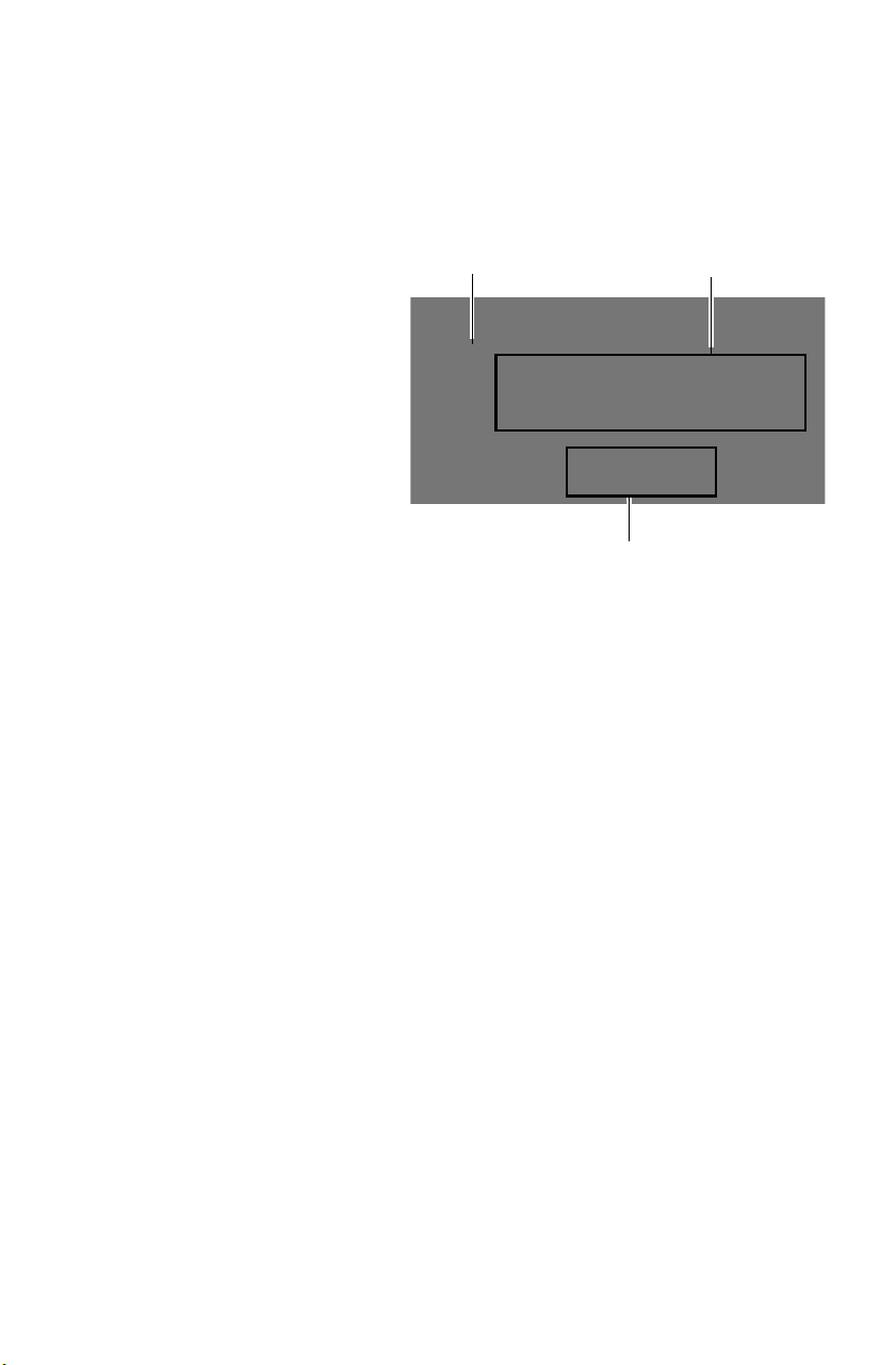
Engine Error Codes
The error screen displays
only when the CHECK
ENGINE light is on or when
it goes on and off during one
ignition cycle. Error codes
are not stored in the gauge
when the key is turned off.
The code and message is
lost, but will reappear if the
fault reoccurs after restarting
the engine.
If the CHECK ENGINE
light illuminates, retrieve the
error codes from the display. Please see your Polaris dealer for all major
repairs.
1. If the error codes are not displayed, use the MODE button to toggle
until “Ck ENG” displays on the main line of the display.
2. Press and hold the MODE button to enter the diagnostics code
menu.
3. Record the numbers displayed in the gear position (if any), clock
and odometer displays.
4. Press the MODE button to advance to the next error code.
5. Press and hold the MODE button to exit the diagnostics code menu.
6. See pages 48-50 for code definitions and failure descriptions. Please
see your Polaris dealer for all major repairs.
Error Code
Number (0-9)
Suspect Parameter
Number (SPN)
Failure Mode Indicator (FMI)

48
FEATURES AND CONTROLS
Instrument Cluster
Diagnostic Display Code Definitions
Open Load: There is a break in the wires that lead to the item listed in
the chart (injector, fuel pump, etc.), or the item has failed.
Short-to-Ground
: The wire is shorted to ground between the electronic
control unit and the item listed in the chart.
Shorted Load
: The wires leading to the item listed in the chart are
shorted together, or the item has shorted internally.
Short-to-Battery
: The wire leading from the item listed in the chart to
the electronic control unit is shorted to a wire at battery voltage.
Diagnostic Codes
Component Condition SPN FMI
Accelerator
Position 2
Data Erratic, Intermittent Or Incorrect 29 2
Voltage Above Normal, Or Shorted To High Source 29 3
Voltage Below Normal, Or Shorted To Low Source 29 4
Throttle Position
Sensor 1
Data Valid But Above Normal Operational Range - Most
Severe Level
51 0
Data Valid But Below Normal Operational Range - Most
Severe Level
51 1
Data Erratic, Intermittent Or Incorrect 51 2
Voltage Above Normal, Or Shorted To High Source 51 3
Voltage Below Normal, Or Shorted To Low Source 51 4
Abnormal Rate Of Change 51 10
Out Of Calibration 51 13
Vehicle Speed
Sensor
Data Valid But Above Normal Operational Range - Most
Severe Level
84 0
Data Valid But Below Normal Operational Range - Most
Severe Level
84 1
Data Erratic, Intermittent Or Incorrect 84 2
Voltage Above Normal, Or Shorted To High Source 84 3
Voltage Below Normal, Or Shorted To Low Source 84 4
Abnormal Frequency Or Pulse Width Or Period 84 8
Abnormal Update Rate 84 9
Abnormal Rate Of Change 84 10
Bad Intelligent Device Or Component 84 12
Received Network Data In Error 84 19
Accelerator
Position 1
Data Erratic, Intermittent Or Incorrect 91 2
Voltage Above Normal, Or Shorted To High Source 91 3
Voltage Below Normal, Or Shorted To Low Source 91 4
Manifold Absolute
Pressure Sensor
Data Erratic, Intermittent Or Incorrect 102 2
Voltage Above Normal, Or Shorted To High Source 102 3
Voltage Below Normal, Or Shorted To Low Source 102 4
Mechanical System Not Responding Or Out Of Adjustment 102 7
Abnormal Rate Of Change 102 10

49
FEATURES AND CONTROLS
Instrument Cluster
Diagnostic Display Code Definitions
Diagnostic Codes
Component Condition SPN FMI
Intake Air
Temperature Sensor
Data Erratic, Intermittent Or Incorrect 105 2
Voltage Above Normal, Or Shorted To High Source 105 3
Voltage Below Normal, Or Shorted To Low Source 105 4
Abnormal Rate Of Change 105 10
Data Valid But Above Normal Operating Range - Least
Severe Level
105 15
Engine Temperature
Sensor
Data Valid But Above Normal Operational Range - Most
Severe Level
110 0
Data Erratic, Intermittent Or Incorrect 110 2
Voltage Above Normal, Or Shorted To High Source 110 3
Voltage Below Normal, Or Shorted To Low Source 110 4
Abnormal Rate Of Change 110 10
Data Valid But Above Normal Operating Range - Least
Severe Level
110 15
Data Valid But Above Normal Operating Range - Moderately
Severe Level
110 16
Data Valid But Below Normal Operating Range - Least
Severe Level
110 17
System Power Data Valid But Above Normal Operational Range - Most
Severe Level
168 0
Data Valid But Below Normal Operational Range - Most
Severe Level
168 1
Voltage Above Normal, Or Shorted To High Source 168 3
Voltage Below Normal, Or Shorted To Low Source 168 4
Data Valid But Above Normal Operating Range - Moderately
Severe Level
168 16
Data Valid But Below Normal Operating Range - Moderately
Severe Level
168 18
Engine Speed Data Valid But Above Normal Operational Range - Most
Severe Level
190 0
Data Valid But Below Normal Operational Range - Most
Severe Level
190 1
Data Erratic, Intermittent Or Incorrect 190 2
Mechanical System Not Responding Or Out Of Adjustment 190 7
Received Network Data In Error 190 19
Condition Exists 190 31
Gear Sensor Signal Data Erratic, Intermittent Or Incorrect 523 2
Voltage Above Normal, Or Shorted To High Source 523 3
Voltage Below Normal, Or Shorted To Low Source 523 4
Abnormal Update Rate 523 9
ECU Memory Bad Intelligent Device Or Component 628 12
Out Of Calibration 628 13
Calibration Out Of Calibration 630 13
Crankshaft Position
Sensor
Data Erratic, Intermittent Or Incorrect 636 2
Abnormal Frequency Or Pulse Width Or Period 636 8
Injector 1 (Front)
(MAG) (SDI Port
Injector)
Voltage Above Normal, Or Shorted To High Source 651 3
Voltage Below Normal, Or Shorted To Low Source 651 4
Current Below Normal Or Open Circuit 651 5

50
FEATURES AND CONTROLS
Instrument Cluster
Diagnostic Display Code Definitions
Diagnostic Codes
Component Condition SPN FMI
Fan Relay Driver
Circuit
Voltage Above Normal, Or Shorted To High Source 1071 3
Voltage Below Normal, Or Shorted To Low Source 1071 4
Current Below Normal Or Open Circuit 1071 5
Ignition Coil Primary
Driver 1 (Front)
(MAG)
Voltage Above Normal, Or Shorted To High Source 1268 3
Voltage Below Normal, Or Shorted To Low Source 1268 4
Current Below Normal Or Open Circuit 1268 5
Fuel Pump Driver
Circuit
Voltage Above Normal, Or Shorted To High Source 1347 3
Voltage Below Normal, Or Shorted To Low Source 1347 4
Current Below Normal Or Open Circuit 1347 5
Oxygen Sensor 1 Data Erratic, Intermittent Or Incorrect 3056 2
Voltage Above Normal, Or Shorted To High Source 3056 3
Voltage Below Normal, Or Shorted To Low Source 3056 4
Bad Intelligent Device Or Component 3056 12
ECU Output Supply
Voltage 1
Data Valid But Above Normal Operational Range - Most
Severe Level
3597 0
Data Valid But Below Normal Operational Range - Most
Severe Level
3597 1
Voltage Above Normal, Or Shorted To High Source 3597 3
Voltage Below Normal, Or Shorted To Low Source 3597 4
Data Valid But Above Normal Operating Range - Moderately
Severe Level
3597 16
Data Valid But Below Normal Operating Range - Moderately
Severe Level
3597 18
ECU Output Supply
Voltage 2
Data Valid But Above Normal Operational Range - Most
Severe Level
3598 0
Data Valid But Below Normal Operational Range - Most
Severe Level
3598 1
Voltage Above Normal, Or Shorted To High Source 3598 3
Voltage Below Normal, Or Shorted To Low Source 3598 4
Data Valid But Above Normal Operating Range - Moderately
Severe Level
3598 16
Data Valid But Below Normal Operating Range - Moderately
Severe Level
3598 18
ECU Output Supply
Voltage 3
Data Valid But Above Normal Operational Range - Most
Severe Level
3599 0
Data Valid But Below Normal Operational Range - Most
Severe Level
3599 1
Voltage Above Normal, Or Shorted To High Source 3599 3
Voltage Below Normal, Or Shorted To Low Source 3599 4
Data Valid But Above Normal Operating Range - Moderately
Severe Level
3599 16
Data Valid But Below Normal Operating Range - Moderately
Severe Level
3599 18
ETC Accelerator
Position Sensor
Outputs 1 & 2
Correlation
Data Erratic, Intermittent Or Incorrect 65613 2

51
FEATURES AND CONTROLS
Instrument Cluster
Diagnostic Display Code Definitions
Diagnostic Codes
Component Condition SPN FMI
Throttle Position Sensor 2 Data Valid But Above Normal Operational Range -
Most Severe Level
520198 0
Data Valid But Below Normal Operational Range -
Most Severe Level
520198 1
Data Erratic, Intermittent Or Incorrect 520198 2
Voltage Above Normal, Or Shorted To High Source 520198 3
Voltage Below Normal, Or Shorted To Low Source 520198 4
Abnormal Rate Of Change 520198 10
Out Of Calibration 520198 13
Active Descent Control
System
Voltage Above Normal, Or Shorted To High Source 520203 3
Voltage Below Normal, Or Shorted To Low Source 520203 4
Current Below Normal Or Open Circuit 520203 5
Fuel Correction Front Data Valid But Above Normal Operating Range -
Least Severe Level
520204 15
Data Valid But Below Normal Operating Range -
Least Severe Level
520204 17
All Wheel Drive Control
Circuit
Voltage Above Normal, Or Shorted To High Source 520207 3
Voltage Below Normal, Or Shorted To Low Source 520207 4
Current Below Normal Or Open Circuit 520207 5
Oxygen Sensor Heater 1 Data Erratic, Intermittent Or Incorrect 520209 2
Voltage Above Normal, Or Shorted To High Source 520209 3
Voltage Below Normal, Or Shorted To Low Source 520209 4
Current Below Normal Or Open Circuit 520209 5
Accelerator Position/Brake
Position Interaction
Condition Exists 520275 31
Throttle Position Sensor (1
or 2 Indeterminable)
Data Erratic, Intermittent Or Incorrect 520276 2
Bad Intelligent Device Or Component 520276 12
Throttle Body Control -
Power Stage
Data Erratic, Intermittent Or Incorrect 520277 2
Voltage Above Normal, Or Shorted To High Source 520277 3
Voltage Below Normal, Or Shorted To Low Source 520277 4
Abnormal Frequency Or Pulse Width Or Period 520277 8
Condition Exists 520277 31
Throttle Body Control -
Return Spring Check Failed
Condition Exists 520278 31
Throttle Body Control -
Adaption Aborted
Condition Exists 520279 31
Throttle Body Control -
Limp Home Position Check
Failed
Condition Exists 520280 31
Throttle Body Control -
Mechanical Stop
Adaptation Failure
Condition Exists 520281 31
Throttle Body Control -
Repeated Adaptation
Failed
Condition Exists 520282 31
Throttle Body Control Data Erratic, Intermittent Or Incorrect 520283 2
Voltage Above Normal, Or Shorted To High Source 520283 3
Voltage Below Normal, Or Shorted To Low Source 520283 4

52
FEATURES AND CONTROLS
Instrument Cluster
Diagnostic Display Code Definitions
Diagnostic Codes
Component Condition SPN FMI
Throttle Body Control - Position Deviation
Fault
Condition Exists 520284 31
ECU Monitoring Error Condition Exists 520286 31
ECU Monitoring Error (Level 3) Condition Exists 520287 31
ECU Monitoring of Injection Cut Off
(Level 1)
Condition Exists 520288 31
ECU Monitoring of Injection Cut Off
(Level 2)
Condition Exists 520289 31
Throttle Body Control - Requested
Throttle Angle Not Plausible
Condition Exists 520305 31
ECU ADC Fault - No Load Condition Exists 520306 31
ECU ADC Fault - Voltage Condition Exists 520307 31
Accelerator Sensor Sync Fault - Sensor
Diff Exceeds Limit
Condition Exists 520308 31
ECU Fault - ICO Condition Exists 520309 31
ECU Fault - Hardware Disruption Condition Exists 520311 31
Idle Fuel Correction Bank 1 Data Valid But Above Normal
Operating Range - Least Severe
520342 15
Data Valid But Below Normal
Operating Range - Least Severe
520342 17
Adaptive Fuel Correction Bank 1 Data Valid But Above Normal
Operating Range - Least Severe
520344 15
Data Valid But Below Normal
Operating Range - Least Severe
520344 17
EPS Models Only
Steering Over Current Shut Down Current Above Normal Or Grounded
Circuit
520221 6
Steering Excessive Current Error Current Above Normal Or Grounded
Circuit
520222 6
Steering Torque Partial Failure Condition Exists 520223 31
Steering Torque Full Failure Condition Exists 520224 31
EPAS Inverter Temperature Data Valid But Above Normal
Operational Range - Most Severe
520225 0
Data Valid But Above Normal
Operating Range - Severe
520225 16
EPAS Communications Receive Data
Error
Data Erratic, Intermittent Or Incorrect 520226 2
Condition Exists 520226 31
Position Encoder Error Root Cause Not Known 520228 11
Bad Intelligent Device Or Component 520228 12
Condition Exists 520228 31
EPAS Software Error Bad Intelligent Device Or Component 520229 12
Condition Exists 520229 31
EPAS Power Save Condition Condition Exists 520231 31
EPS SEPIC Voltage Error Voltage Above Normal, Or Shorted To
High Source
524086 3
Voltage Below Normal, Or Shorted To
Low Source
524086 4

53
OPERATION
Break-In Period
The break-in period for your new POLARIS Tractor is the first 20 hours
of operation. No single action on your part is as important as following
the procedures for a proper break-in. Careful treatment of a new engine
and drive components will result in more efficient performance and
longer life for these components.
NOTICE: Excessive heat build-up during the first three hours of operation will
damage close-fitted engine parts and drive components. Do not
operate at full throttle or high speeds during the first three hours of
use.
Engine and Drivetrain Break-in
1. Fill the fuel tank with the recommended fuel. See page 30.
2. Check the engine oil level. See page 98. Add oil if necessary.
3. Select an open area that allows room to familiarize yourself with
vehicle operation and handling.
4. Drive slowly. Vary the throttle positions. Do not operate at sustained
idle.
5. Perform regular checks on fluid levels, controls and areas outlined
on the daily pre-ride inspection checklist. See page 54.
6. Pull only light loads.
7. Change both the oil and the filter at 25 hours.
8. Check fluid levels of transmission and all gearcases after the first 25
hours of operation and every 100 hours thereafter.
PVT Break-in (Clutches/Belt)
A proper break-in of the clutches and drive belt will ensure a longer life
and better performance. Break in the clutches and belt by operating at
slower speeds during the break-in period as recommended. Pull only
light loads. Avoid aggressive acceleration and high speed operation
during the break-in period.
If a belt fails, always clean away all debris when replacing the belt.

54
OPERATION
Pre-Ride Checklist
Item Remarks Page
Hand brake/lever travel Ensure proper operation 109
Foot brake Ensure proper operation 109
Brake fluid Ensure proper level 109
Front suspension Inspect, lubricate if necessary 96
Rear suspension Inspect, lubricate if necessary 96
Steering Ensure free operation -
Tires Inspect condition and pressure 115
Wheels/fasteners Inspect, ensure fastener tightness 115
116
Frame nuts, bolts, fasteners Inspect, ensure tightness -
Fuel and oil Ensure proper levels 30
97
Coolant level (if applicable) Ensure proper level 104
105
Coolant hoses (if applicable) Inspect for leaks -
Throttle Ensure proper operation 27
Indicator lights/switches Ensure operation 24
Engine stop switch Ensure proper operation 25
Mirrors Adjust for best side/rear vision 27
Air filter, pre-filter Inspect, clean 117
Air box sediment tube Drain deposits whenever visible -
Headlamp Check operation, apply POLARIS
dielectric grease when lamp is
replaced
121
Brake light/taillight Check operation, apply POLARIS
dielectric grease when lamp is
replaced
123
Riding gear Wear approved helmet, goggles, and
protective clothing
9
Winch Inspect cable and switch 78-89
55
OPERATION
Boarding and Dismounting the Tractor
Boarding
If boarding from the left side of the
vehicle, grasp the left handlebar grip
with your left hand. Step onto the
footrest and place your right foot and
leg across the seat. Sit astride the
vehicle.
If boarding from the right side of the vehicle, grasp the right handlebar
grip with your right hand. Step onto the footrest and place your left foot
and leg across the seat. Sit astride the vehicle.
Dismounting
1. Position the vehicle on a level
surface.
2. Place the transmission in PARK
(or neutral).
3. Stand on the footrests and
dismount the vehicle, holding onto the handlebar for support.
56
OPERATION
Starting the Engine
NOTICE: Operating the vehicle immediately after starting could cause engine
damage. Allow the engine to warm up for several minutes before
operating.
1. Position the vehicle on a level
surface.
2. Place the transmission in PARK
(or neutral).
Tip: The starter interlock will prevent the
engine from starting if the
transmission is in gear and the brake is not engaged.
3. Sit on the vehicle.
4. Apply the brakes.
5. Move the engine stop switch to RUN.
6. Do not press the throttle while starting the engine.
7. Turn the ignition key past the PARKING
LIGHTS ON position to engage the
starter. Activate the starter for a
maximum of five seconds, releasing the
key when the engine starts.
8. If the engine does not start, release the
starter and wait five seconds.
9. Repeat steps 7 and 8 until the engine
starts.
Stopping the Engine
1. Apply the brakes to stop the vehicle.
2. Place the transmission in PARK.
3. Turn the ignition key to the STOP (OFF) position or press the
engine stop switch down to stop the engine.

57
OPERATION
Cold Weather Operation
Internal engine condensation increases as outside temperatures
decrease. If the vehicle is used year-round, check the oil level
frequently. A rising oil level could indicate condensation in the bottom
of the oil tank, which can lead to engine damage. Any condensation
must be drained.
Always operate the engine long enough to reach operating temperature,
which reduces condensation. See your POLARIS dealer for engine
heater kits, which provide quicker warm-ups and easier starting in cold
weather.
PVT Operation
When To Use Low Range and High Range
Condition Range to Use
Operating at speeds less than 11 km/h Low
Towing heavy loads Low
Operating in rough or rugged terrain Low
Operating at speeds greater than 11 km/h High

58
OPERATION
Driving Procedures
1. Wear protective riding gear. See page 9.
2. Perform the pre-ride inspection. See page 54.
3. Sit upright. Keep your feet on the footrests. Keep both hands on the
handlebars.
4. Start the engine and allow it to warm up.
5. Apply the brakes.
6. Shift the transmission into gear.
7. Check your surroundings and determine your path of travel.
8. Release the brakes.
9. Slowly squeeze the throttle lever toward the handlebar to begin
driving.
10. Drive slowly. Practice maneuvering and using the throttle and
brakes on level surfaces.
59
OPERATION
Driving with a Passenger
1. Never carry more than one passenger on a 2-up vehicle.
2. Do not carry a passenger on a 2-up vehicle until you have at least
two hours of driving experience with the vehicle.
3. Never allow anyone under 12 years of age to ride as a passenger on
a 2-up vehicle. Make sure any passenger is tall enough to
comfortably and safely reach the grab handles and footrests. Allow
a passenger to ride only in the approved passenger seat.
4. Make sure the passenger is wearing appropriate riding gear,
including an approved helmet with a rigid chin guard. See page 9.
5. Perform the pre-ride
inspection. See page 54.
6. Lock the parking brake.
7. Board the vehicle from the
left side. After the operator
is seated, the passenger
should board the vehicle
from the left side. See page
55. Always make sure the
parking brake lock is
engaged to ensure the
vehicle remains motionless
whenever a passenger
boards or dismounts.
8. Slow down. Control may be more difficult with a passenger on
board. Allow more time and distance for braking.

60
OPERATION
Driving with a Passenger
9. Ride to the ability of your passenger, instead of to your own ability.
Avoid unexpected or aggressive maneuvers that could cause a
passenger to fall from the vehicle.
10. Do not cross a hillside with a passenger on board. See page 64.
11. A passenger should always be seated in the passenger seat with both
feet on the footrests and both hands on the passenger grab handles
at all times. The passenger should never hold on to the operator.
Never secure a passenger to the vehicle or to the operator with a
belt, rope or similar device.
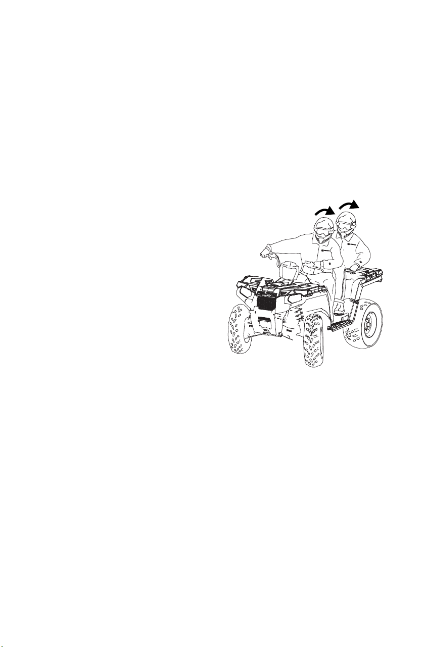
12. Make sure the passenger understands the importance of “active
riding.” When hill-climbing or performing maneuvers, a passenger
should shift body weight in the same manner in which the driver
shifts body weight. For example, the passenger should lean to the
inside of a turn along with the operator and should always lean
uphill when climbing and descending hills.
61
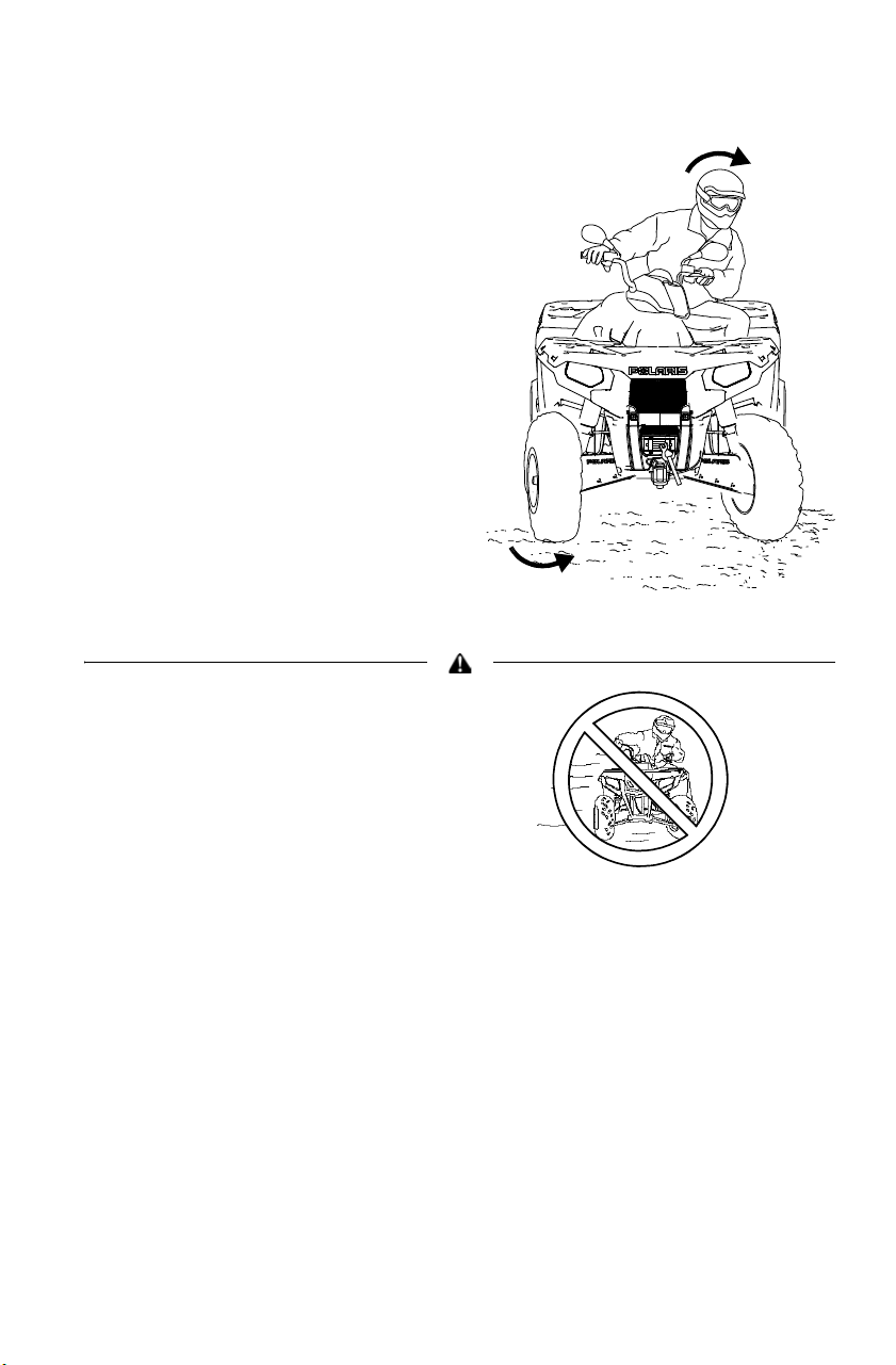
OPERATION
Turning the Vehicle
1. Before turning, activate a turn
signal to alert others of your
intentions. Activate the left
signal before a left turn.
Activate the right signal before
a right turn.
2. Steer in the direction of the
turn, leaning your upper body
to the inside of the turn while
supporting your weight on the
outer footrest. Use the same
leaning technique for turning in
reverse.
3. Never turn quickly when
carrying a passenger or cargo.
4. Practice making turns at slow
speeds before attempting to
turn at faster speeds.
Always follow the procedures
outlined in this manual for turning.
Never turn sharply at excessive
speeds, which can lead to vehicle
rollover.

62
OPERATION
Driving Uphill
Whenever traveling uphill, follow these precautions:
1. Always move the AWD switch to ADC AWD (if equipped) before
ascending or descending a hill. See page 37.
2. Avoid steep hills. Maximum incline is:
• 15° (Touring)
• 15° (570/450 HO)
3. Avoid hills with slippery or loose surfaces.
4. Keep both feet on the footrests.
5. Shift body weight uphill. A passenger should also shift body weight
uphill.
6. Drive straight uphill.
7. Proceed at a steady rate of speed to avoid stalling.
8. Be alert. Be prepared to take emergency action. This may include
dismounting quickly.
9. Never open the throttle suddenly or make sudden gear changes.
10. Never go over the top of a hill at high speed.
Touring
15° Maximum
570/450 HO
15° Maximum
63
OPERATION
Driving Uphill
If all forward speed is lost:
1. Lean forward to keep body weight uphill. A passenger should also
lean uphill.
2. Apply the brakes.
3. When fully stopped, lock the hydraulic parking brake.
4. Dismount on the uphill side of the vehicle, or on the left if the
vehicle is pointing straight uphill. Have a passenger dismount first,
then the operator may dismount.
If the vehicle begins rolling downhill, never apply engine power. Never
apply the brakes aggressively while rolling backwards.
1. Lean forward to keep body weight uphill. A passenger should also
lean uphill.
2. Apply the brakes gradually.
3. When fully stopped, lock the hydraulic parking brake.
4. Dismount on the uphill side of the vehicle, or on the left if the
vehicle is pointing straight uphill. Have a passenger dismount first,
then the operator may dismount.
5. Use the K-turn to turn around. See page 66.
Always follow the procedures outlined in this
manual for braking if you stall or roll
backwards while climbing a hill. Never back
down a hill.
64
OPERATION
Driving on a Sidehill (Sidehilling)
Avoid crossing the side of a hill (sidehilling) if possible. If sidehilling is
necessary, follow these precautions:
1. Slow down.
2. Avoid hills with slippery or loose surfaces.
3. Avoid crossing the sides of steep hills.
4. Do not cross a hillside with a passenger on board. Ask the passenger
to dismount and walk across the hillside before reboarding the
vehicle.
5. Shift body weight uphill.
6. Keep your feet on the footrests.
7. If the vehicle begins to tip, quickly turn the front wheel downhill, if
possible, or dismount on the uphill side immediately!
Always follow the procedures outlined in this
manual for crossing the side of a hill.
Never attempt to turn the Tractor around on
any hill until you've mastered (on level
ground) the turning technique outlined in this
manual.
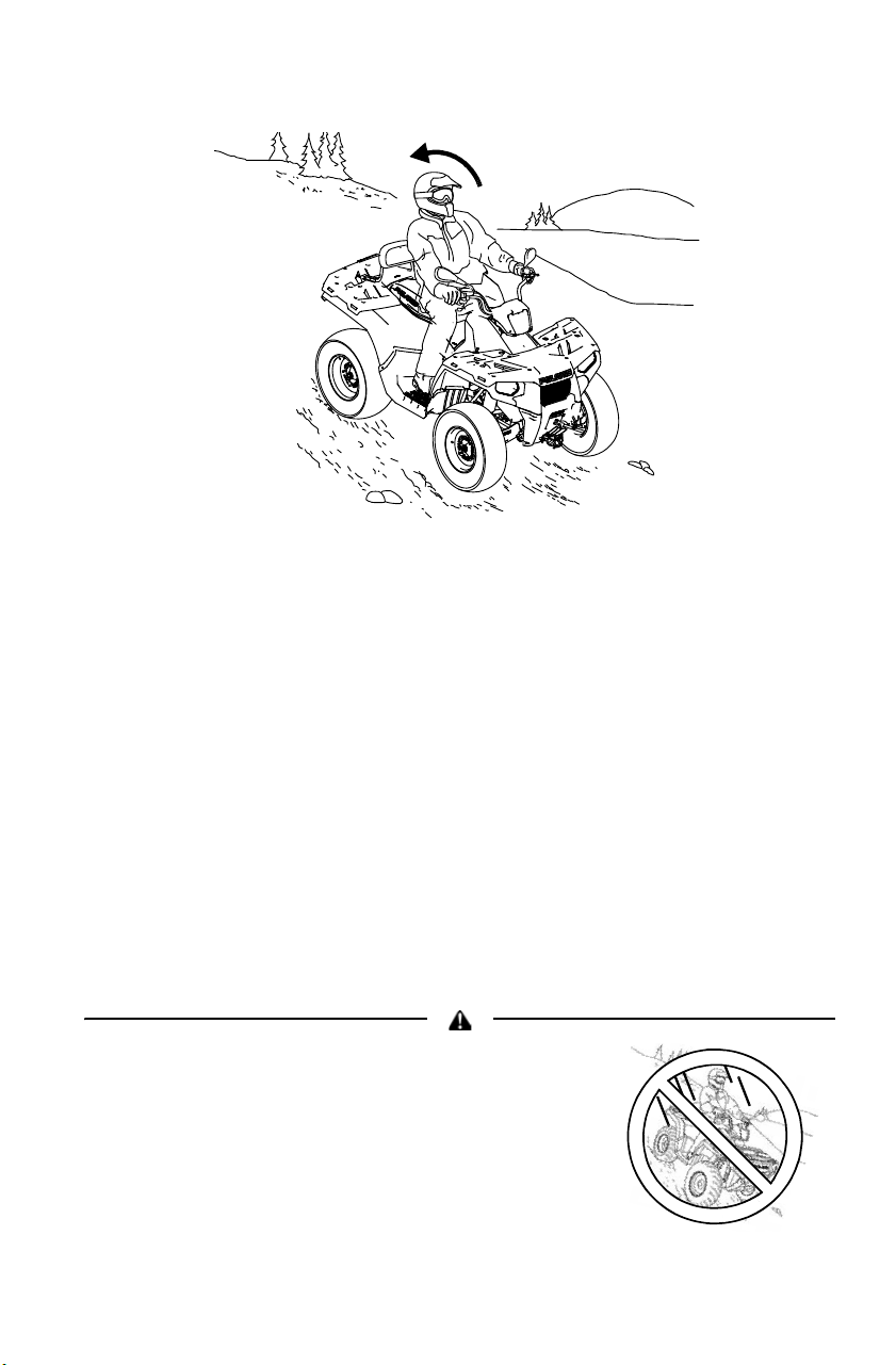
65
OPERATION
Driving Downhill
When driving downhill, follow these precautions:
1. Always move the AWD switch to ADC AWD (if equipped) before
ascending or descending a hill. See page 37.
2. Avoid steep hills. Maximum incline is:
• 15° (Touring)
• 15° (570/450 HO)
3. Avoid hills with slippery or loose surfaces.
4. Never drive downhill at high speed. Slow down.
5. Drive straight downhill. Avoid driving downhill at an angle, which
can cause the vehicle to pitch sharply to one side.
6. Shift body weight uphill. A passenger should also shift body weight
uphill.
7. Apply the brakes slightly to aid in slowing.
Always follow the procedures outlined in this
manual for driving downhill and for braking
on hills.
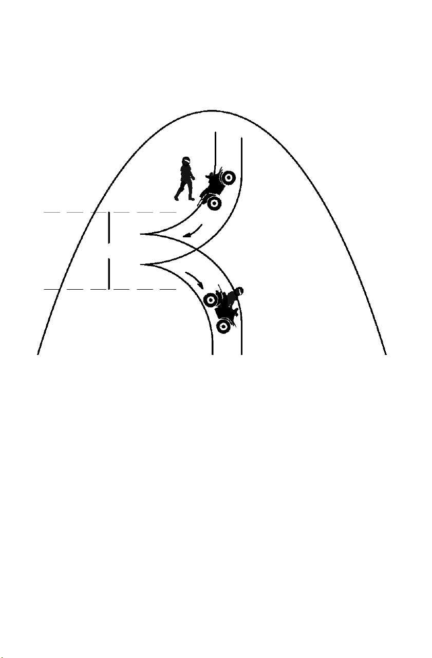
66
OPERATION
Turning Around on a Hill (K-Turn)
If the vehicle stalls while climbing a hill, never back it down the hill!
Use the K-turn to turn around.
1. Always move the AWD switch to ADC AWD (if equipped) before
ascending or descending a hill. See page 37.
2. Stop the vehicle. Keep body weight uphill.
3. Lock the hydraulic parking brake.
4. Leave the transmission in forward gear. Turn the engine off.
5. If a passenger is on board, ask the passenger to dismount first, then
the operator may dismount. Dismount on the uphill side of the
vehicle, or on the left if the vehicle is pointing straight uphill. A
passenger should not remount until the vehicle returns to firm, level
ground.
6. Staying uphill of the vehicle, and turn the handlebars full left.
7. Squeeze the brake lever to release the parking brake.
8. Slowly release the brake lever and allow the vehicle to roll around
to your right until it's pointing across the hill or slightly downward.
2.4 m
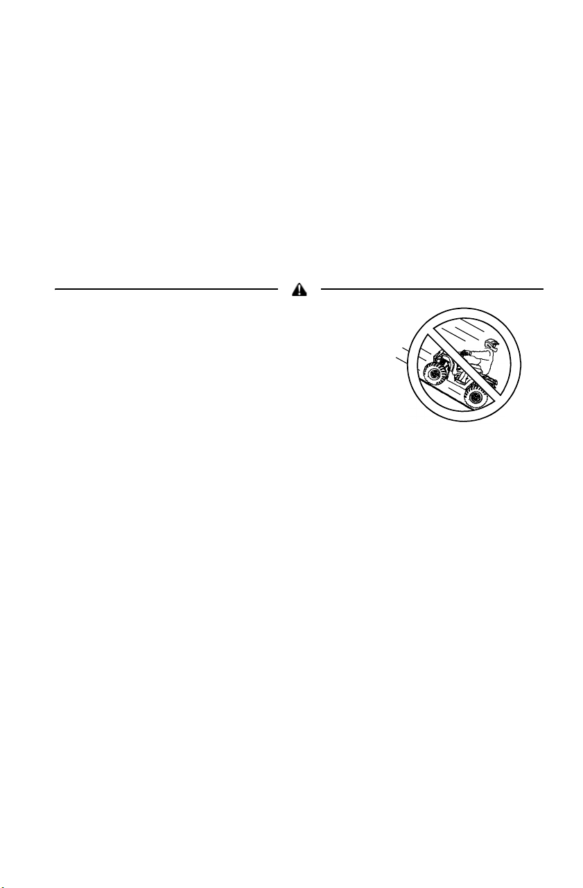
67
OPERATION
Turning Around on a Hill (K-Turn)
9. Lock the hydraulic parking brake.
10. Remount from the uphill side. Keep your weight uphill. A passenger
should not remount until the vehicle returns to firm, level ground.
11. Apply the foot brake.
12. With the transmission still in forward, start the engine.
13. Squeeze and release the brake lever to release the parking brake.
14. Release the foot brake and drive slowly downhill. Control speed
with either the hand or foot brake until the vehicle is on level
ground.
Always follow the procedures outlined in this
manual for braking if you stall or roll
backwards while climbing a hill. Never back
down a hill.
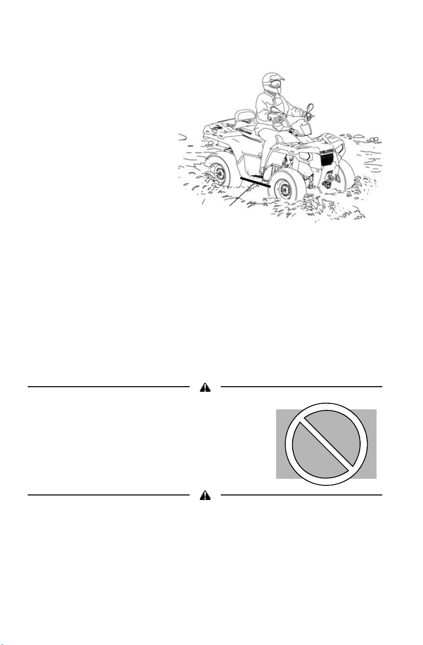
68
OPERATION
Driving Through Water
Follow these procedures
when driving through
water:
1. Check water depth and
current before crossing.
2. Choose a crossing
where both banks have
gradual inclines.
3. Drive slowly. Avoid
rocks and obstacles.
4. Avoid operating in
water deeper than the
bottom of the footrests.
If it's unavoidable,
travel slowly, balance your weight carefully and avoid sudden
movements. Maintain a slow and steady forward motion. Do not
make sudden turns, stops or throttle changes.
5. Wet brakes may have reduced stopping ability. Dry the brake pads
by driving slowly and applying the brakes lightly several times until
braking action is normal.
6. If your vehicle becomes fully immersed, and it's impossible to take
it to a dealer before starting it, follow the steps described on page
128. Have the vehicle serviced by your dealer promptly.
Always follow the procedures outlined in this
manual for driving through water. Never drive
through deep or fast-flowing water.
If the vehicle stops while fully submerged, major engine damage can result if the
machine is not thoroughly inspected. Take the vehicle to your dealer before
starting the engine.
Maximum
Depth
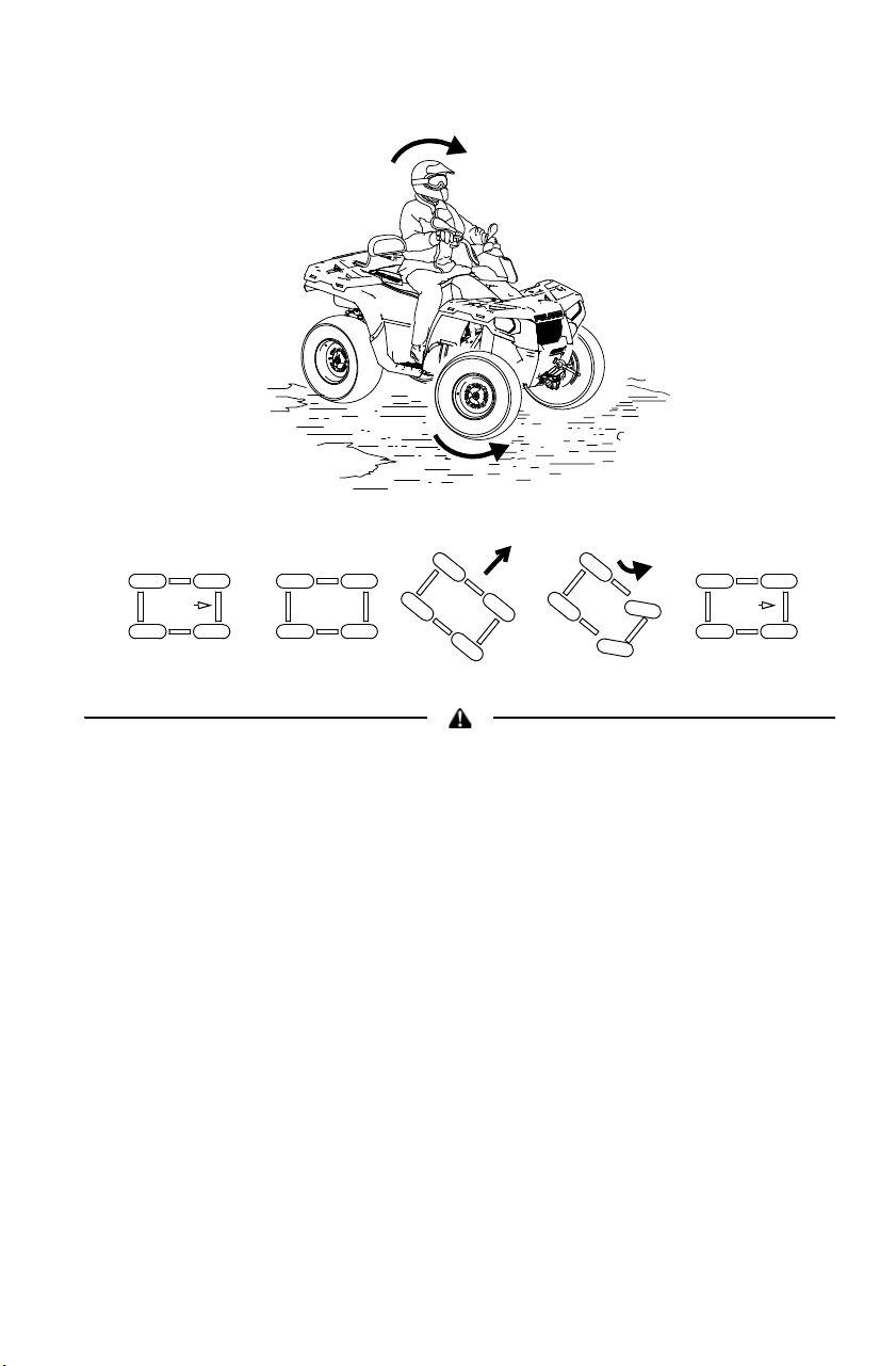
69
OPERATION
Driving on Slippery Surfaces
Always follow the procedures outlined in this manual for operating on slippery or
loose surfaces. Use extra caution. Always avoid skidding or sliding.
Whenever driving on slippery or loose surfaces such as wet trails,
gravel, snow or ice, follow these precautions:
1. Slow down before driving onto slippery surfaces.
2. Engage AWD before wheels begin to lose traction.
3. Be alert. Watch the trail.
4. Avoid quick, sharp turns.
5. Correct a skid by turning the handlebars in the direction of the skid
and shifting your body weight forward.
6. Never apply the brakes during a skid.
NOTICE: Severe damage to drive train may occur if AWD is engaged while the
wheels are spinning. Engage AWD when the wheels have traction.
Sideways
skid
Turn in
direction of
skid
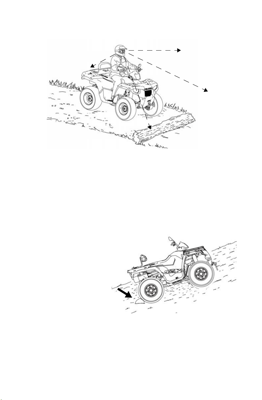
70
OPERATION
Driving Over Obstacles
1. Always check for obstacles before operating in a new area.
2. Be alert. Watch the terrain. Use extra caution.
3. Never attempt to operate over large obstacles, such as rocks or
fallen trees.
4. Always have a passenger dismount before operating over an
obstacle that could cause a fall from the vehicle or vehicle tipover.
Parking on an Incline
Avoid parking on an incline.
If it's unavoidable, follow
these precautions:
1. Stop the engine.
2. Place the transmission
in PARK.
3. Always block the rear
wheels on the downhill
side.
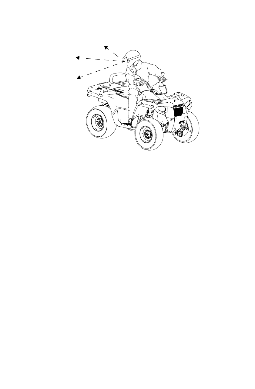
71
OPERATION
Driving in Reverse
Follow these precautions when operating in reverse:
1. Always check for obstacles or people behind the vehicle before
backing. Be aware that a passenger can obstruct your view.
2. Avoid backing downhill.
3. Drive slowly. Apply the brakes lightly for stopping.
4. Avoid turning at sharp angles.
5. Never open the throttle suddenly.
6. Do not use the override switch unless additional power is required
for vehicle movement. Use with caution.
NOTICE: Excessive throttle operation while in the speed limit mode may cause
fuel to build in the exhaust, resulting in engine popping and/or engine
damage.

72
OPERATION
Hauling Cargo
Overloading the vehicle or carrying or towing cargo improperly can alter vehicle
handling and may cause loss of control or brake instability. Always follow these
precautions when hauling cargo.
• Read and understand the load distribution warnings listed on the vehicle
warning labels.
• NEVER EXCEED THE MAXIMUM WEIGHT CAPACITY of the vehicle. When
determining the weight you are adding to the vehicle, include the weight of
the operator, passenger, accessories, loads in the racks or box and the load
on the trailer tongue. The combined weight of these items must not exceed
the maximum weight capacity.
• REDUCE SPEED AND ALLOW GREATER DISTANCES FOR BRAKING
WHEN HAULING CARGO OR TOWING. Use extreme caution when applying
brakes. Avoid situations that require backing downhill.
• When operating over rough or hilly terrain, reduce speed, cargo and towed
load to maintain stable driving conditions.
• DO NOT BLOCK THE FRONT HEADLIGHT BEAM when carrying loads on a
front rack.
• WEIGHT DISTRIBUTION in a cargo bed should be as far forward and as low
as possible. Balance loads proportionally between the front rack and cargo
bed, but do not exceed the stated load capacity. Carrying a load on only the
front rack or cargo bed may cause an imbalanced condition and increases the
possibility of vehicle rollover. Always be sure that the cargo bed is lowered
and latched before moving the vehicle.
• WEIGHT DISTRIBUTION on models with front and rear racks should be 1/3
on the front rack and 2/3 on the rear rack. Carrying loads on only one rack
increases the possibility of vehicle rollover.
• Carrying a high load raises the center of gravity and creates a less stable
operating condition. Reduce load weight when cargo is high. When handling
off-centered loads that cannot be centered, secure the load and operate with
extra caution.
• USE EXTREME CAUTION when operating with loads that extend over the
rack sides. Stability and maneuverability may be adversely affected, causing
the vehicle to overturn.
• Always attach the tow load to the hitch point designated for your vehicle.
• TOWING SPEED should never exceed 16 km/h. Never exceed 8 km/h when
towing loads in rough terrain, while cornering, or while ascending or
descending hills.

73
OPERATION
Hauling Cargo
1. Always read and understand the
load distribution warning labels
on the vehicle. Never exceed the
weight capacities specified for
the vehicle.
2. On models with front and rear
racks, cargo weight should be
evenly distributed (1/3 on the
front rack and 2/3 on the rear
rack) and mounted as low as
possible.
1/3
2/3
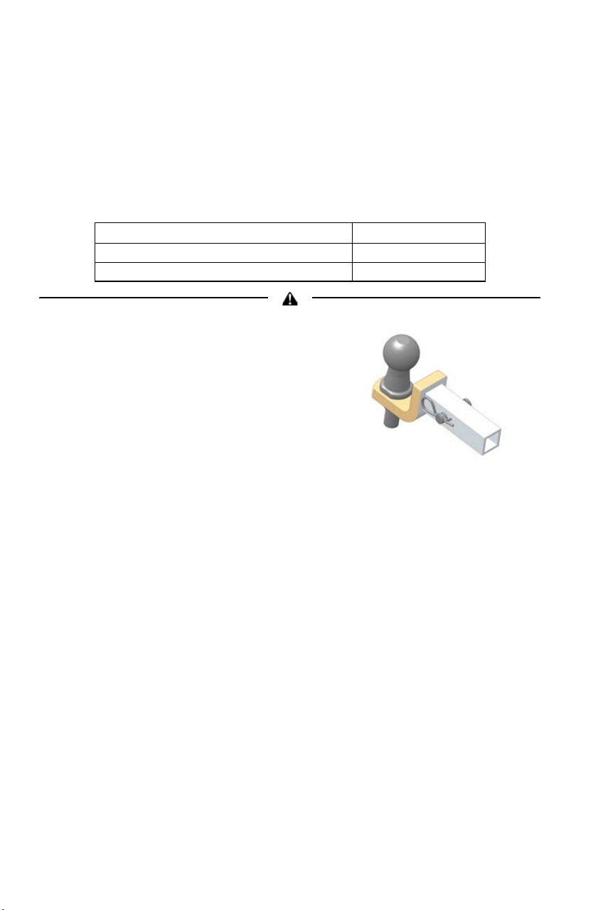
74
OPERATION
Hauling Cargo
Towing Loads
Do not tow any trailer on a grade steeper than 15°.
• The combination of rear rack cargo weight and tongue weight must
not exceed the rear rack capacity.
• The total load (operator, passenger, accessories, cargo and weight on
hitch) must not exceed the maximum weight capacity of the vehicle.
Using an improper hitch or exceeding the
maximum tongue weight capacity can result
in serious damage to the vehicle and will void
your warranty. Never install a hitch longer
than 10 cm. Never install automotive
accessories on your POLARIS Tractor.
Always install POLARIS-approved (or
equivalent) accessories designed for
Tractor use.
Capacities Rear Hitch
Maximum Towed Load (Level Ground) 830 kg
Maximum Vertical Hitch Weight 75 kg
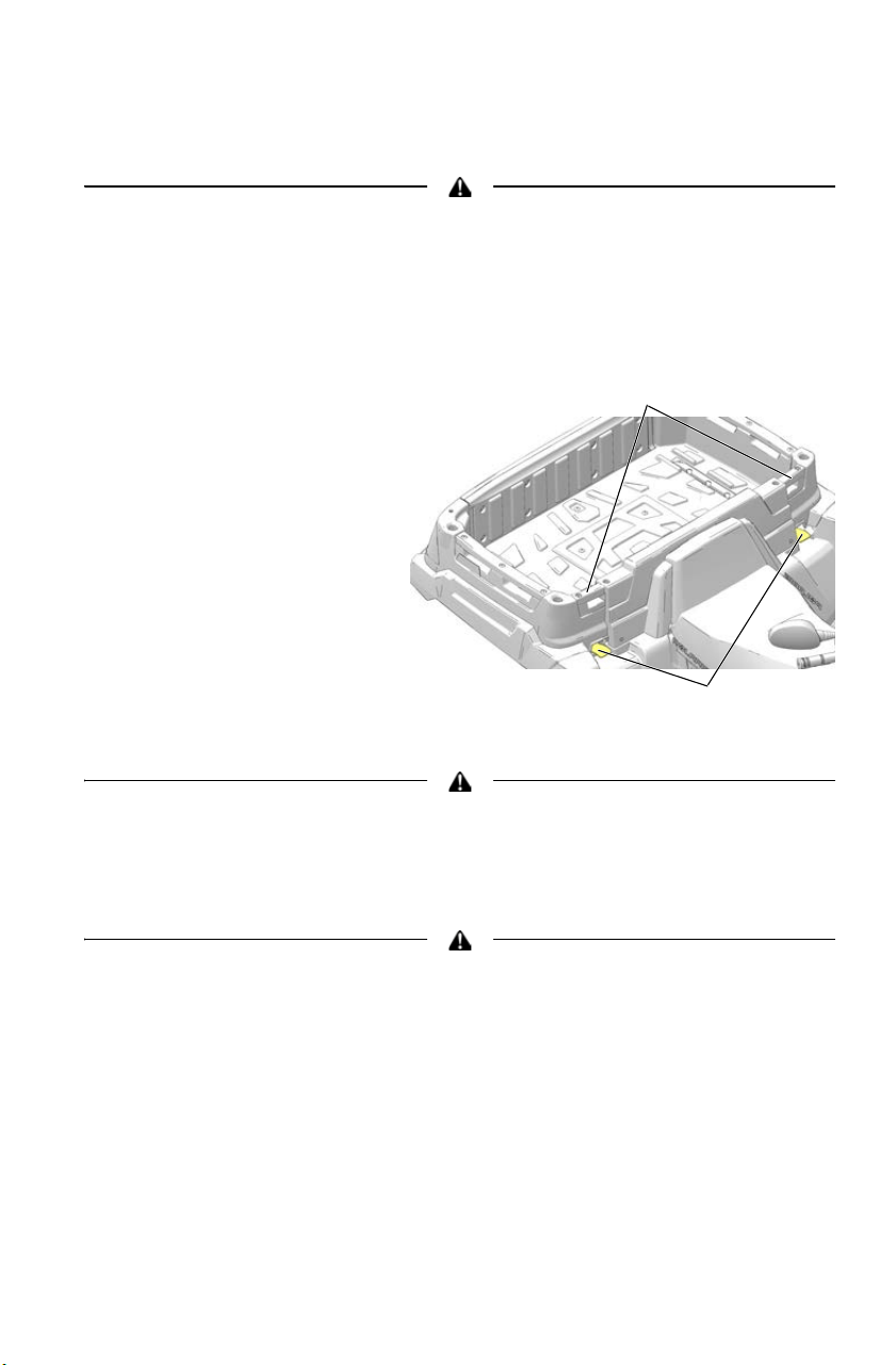
75
OPERATION
Hauling Cargo
Dumping Cargo (X2)
If cargo weight is placed toward the rear of the cargo box, the load may dump
unexpectedly and cause serious injury. When loading cargo, always position the
weight as far forward and as low as possible.
1. Select a level site to dump the cargo box. Do not attempt to dump or
unload the vehicle while parked on an incline.
2. Place the transmission
in PARK.
3. Lock the parking brake.
4. Dismount the vehicle.
5. Lower the tailgate.
6. Pull one of the two
cargo box release levers
upward.
7. Firmly grasp one of the
cargo box handles and
slowly lift the front of
the cargo box to dump
the cargo.
To prevent a crushing injury to hands and fingers, keep hands and fingers away
from the lower front edge of the cargo box while lowering the box.
8. Lower the cargo box and make sure the release latch is secured.
9. Secure the tailgate.
Driving with the cargo box in the raised position can cause serious injury and
damage to the vehicle. The cargo box could close unexpectedly and injure the
driver. The rear tires will also catch the rear of the bed, damaging the vehicle
and creating hazardous driving conditions. Never drive this vehicle with the
cargo box in the raised position. Never leave this vehicle parked or unattended
with the cargo box in the raised position.
Box Release Levers
Handles
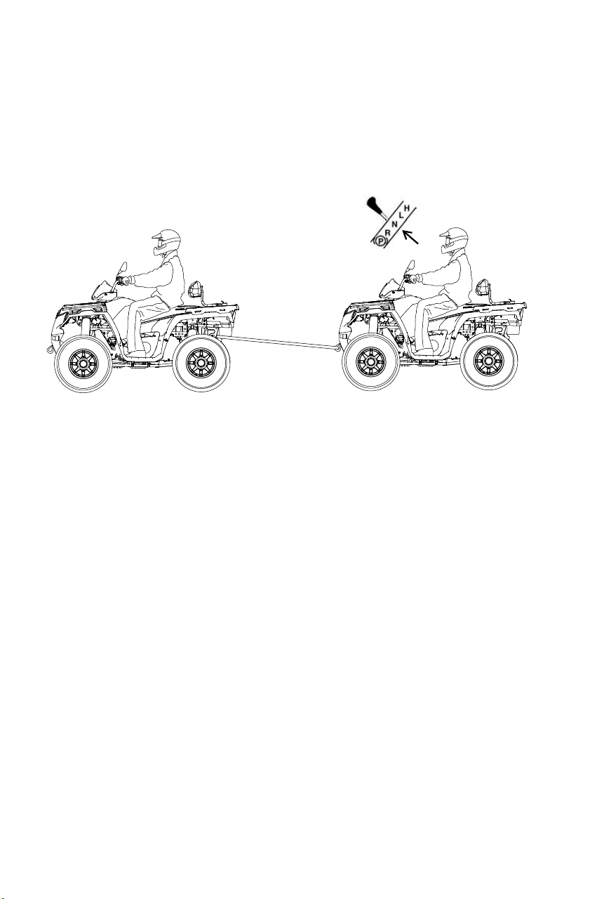
76
OPERATION
Towing the Tractor
If towing the Tractor is necessary, shift the transmission into neutral for
better mobility and to prevent damage to the belt. Always attach the tow
cable to the front tow loop of the disabled Tractor. A rider must be on
board to steer the disabled Tractor while towing.

77
OPERATION
Trailering the Tractor
Follow these procedures when transporting the vehicle.
1. Stop the engine.
2. Place the transmission in PARK.
3. Secure the fuel cap, oil cap and
seat.
4. Remove the key to prevent loss
during transporting.
5. Always tie the frame of the Tractor to the transporting unit securely
with suitable straps or rope. Do not attach tie straps to the front A-
arm bolt pockets, racks or handlebars.

78
WINCH GUIDE
These safety warnings and instructions apply if your vehicle came
equipped with a winch or if you choose to add an accessory winch to
your vehicle.
Improper winch use can result in SEVERE INJURY or DEATH. Always follow all
winch instructions and warnings in this manual.
Your winch may have a cable made of either wire rope or specially
designed synthetic rope. The term “winch cable” will be used for either
unless noted otherwise.
Winch Safety Precautions
1. Read all sections of this manual.
2. Never use alcohol or drugs before or while operating the winch.
3. Never allow children under 16 years of age to operate the winch.
4. Always wear eye protection and heavy gloves when operating the
winch.
5. Always keep body, hair, clothing and jewelry clear of the winch
cable, fairlead and hook when operating winch.
6. Never attempt to “jerk” a load attached to the winch with a moving
vehicle. See the Shock Loading section on page 87.
7. Always keep the area around the vehicle, winch, winch cable and
load clear of people (especially children) and distractions while
operating the winch.
8. Always turn the vehicle ignition power OFF when it and the winch
are not being used.
9. Always be sure that at least five (5) full turns of winch cable are
wrapped around the winch drum at all times. The friction provided
by this wrapped cable allows the drum to pull on the winch cable
and move the load.
10. Always apply your vehicle’s park brake and/or park mechanism to
hold the vehicle in place during winching. Use wheel chocks if
needed.
WARNING
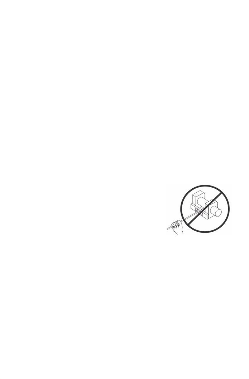
79
WINCH GUIDE
Winch Safety Precautions
11. Always align the vehicle and winch with the load directly in front of
the vehicle as much as possible. Avoid winching with the winch
cable at an angle to the winching vehicle’s centerline whenever
possible.
12. If winching at an angle is unavoidable, follow these precautions:
A. Look at the winch drum occasionally. Never let the winch cable “stack”
or accumulate at one end of the winch drum. Too much winch cable at
one end of the winch drum can damage the winch and the winch cable.
B. If stacking occurs, stop winching. Follow step 15 on page 85 to feed
and rewind the cable evenly before continuing the winch operation.
13. Never winch up or down at sharp angles. This can destabilize the
winching vehicle and possibly cause it to move without warning.
14. Never attempt to winch loads that weigh more than the winch’s
rated capacity.
15. The winch motor may become hot during winch use. If you winch
for more than 45 seconds, or if the winch stalls during operation,
stop winching and permit the winch to cool down for 10 minutes
before using it again.
16. Never touch, push, pull or straddle the
winch cable while winching a load.
17. Never let the winch cable run through
your hands, even if wearing heavy
gloves.
18. Never release the clutch on the winch
when the winch cable is under load.
19. Never use the winch for lifting or
transporting people.

80
WINCH GUIDE
Winch Safety Precautions
20. Never use the winch to hoist or suspend a vertical load.
21. Never immerse or submerse your winch in water. Take your winch
to your dealer for service if this occurs.
22. Always inspect your winch and winch cable before each use.
23. Never winch the hook fully into the winch. This can cause damage
to winch components.
24. Unplug the remote control from the vehicle when the winch is not in
use to prevent inadvertent activation and use by unauthorized
persons.
25. Never grease or oil the winch cable. This will cause the winch cable
to collect debris that will shorten the life of the cable.

81
WINCH GUIDE
Winch Operation
Read the Winch Safety Precautions in the preceding pages before using
your winch.
Tip: Consider practicing the operation and use of your winch before you actually
need to use it in the field.
Improper winch use can result in SEVERE INJURY or DEATH. Always follow all
winch instructions and warnings in this manual.
Each winching situation is unique.
> Take your time to think through the winching you are about to do.
> Proceed slowly and deliberately.
> Never hurry or rush during winching.
> Always pay attention to your surroundings.
> You may need to change your winching strategy if it is not working.
> Always remember that your winch is very powerful.
> There are simply some situations that you and your winch will not be able
to deal with. Do not be afraid to ask others to help when this happens.
1. Always inspect the vehicle, winch, winch cable and winch controls
for any signs of damage or parts in need of repair or replacement
before each use. Pay particular attention to the first 3 feet (1 meter)
of winch cable if the winch is being used (or has been used) for lift-
ing an accessory plow assembly. Promptly replace any worn or
damaged cable.
2. Never operate a winch or a vehicle in need of repair or service.
3. Always apply your vehicle’s
park brake and/or park
mechanism to hold the vehicle
in place during winching. Use
wheel chocks if needed.
WARNING
Hook Strap
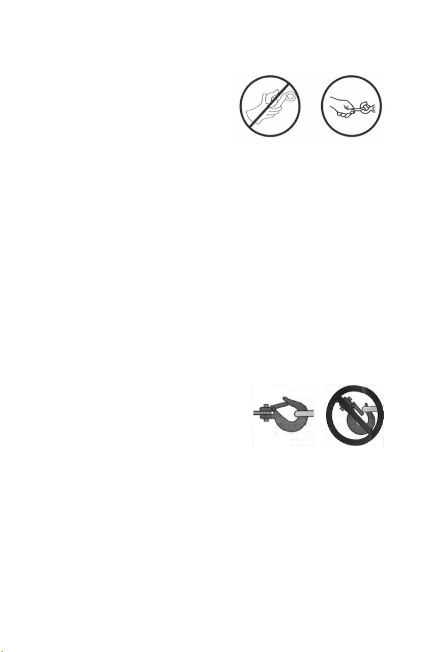
82
WINCH GUIDE
Winch Operation
4. Always use the hook strap when
handling the hook.
WARNING! Never put your fingers into
the hook. This could lead to SEVERE
INJURY.
A. Attach the hook itself onto the
load or use a tow strap or chain
to secure the load to the winch
cable.
Tip: A “tow strap” is NOT intended to stretch. A “recovery strap” is designed to
stretch.
WARNING! Never use a recovery strap when winching due to the excessive
energy that can be released if the winch cable breaks. This can result in
SEVERE INJURY or DEATH. See the Shock Loading section on page 87.
B. Never hook the winch cable back onto itself. This will damage the
winch cable and may result in winch cable failure.
WARNING! Replace the winch cable at the first sign of damage to prevent
SEVERE INJURY or DEATH in the event of failure. For your safety, always
replace POLARIS winch parts (including the cable) with genuine POLARIS
replacement parts available at your authorized POLARIS dealer.
C. If possible, keep the winch cable aligned with the centerline of the
winching vehicle. This will help the spooling of the winch cable and
reduce the load on the fairlead.
D. If freeing a stuck vehicle by attaching to a tree, use an item such as a
tow strap to avoid damaging the tree during winch operation. Sharp
cables and chains can damage and even kill trees. Please remember
to TreadLightly® (treadlightly.org).
E. Before operating the winch, be sure
that the safety latch on the winch
cable hook is fully seated when the
load is attached.
F. Never operate your winch with a
damaged hook or latch. Always
replace damaged parts before using
the winch.
NO YES
NO
YES

83
WINCH GUIDE
Winch Operation
5. Never remove the hook strap from the hook.
6. Release the winch clutch and pull out the winch cable.
7. Pulling out as much cable as possible maximizes the winch’s pulling
capacity. Always be sure that at least five (5) full turns of winch
cable are wrapped around the winch drum at all times. The friction
provided by this wrapped cable allows the drum to pull on the
winch cable and move the load.
8. Read and adhere to the following information for winch damping to
ensure safe winch use.
A. In order to absorb energy that could be released by a winch cable
failure, always place a “damper” on the winch cable. A damper can be
a heavy jacket, tarp, or other soft, dense object. A damper can absorb
much of the energy released if a winch cable breaks when winching.
Even a tree limb can help as a damper if no other items are available to
you.
B. Lay the damper on top of the mid-point of the winch cable length that is
spooled out.
C. On a long pull, it may be necessary to stop winching so that the
damper can be repositioned to the new mid-point of the winch cable.
Always release the tension on the winch cable before repositioning the
damper.
D. Avoid being directly in line with the winch cable whenever possible.
Also, never permit others to stand near or in line with the winch cable
during winch operation.
9. Never hook the winch cable back onto itself. This will damage the
winch cable and may result in winch cable failure.
10. Never use straps, chains or other rigging items that are damaged or
worn.

84
WINCH GUIDE
Winch Operation
11. The ONLY time a winch-equipped vehicle should be moving when
using the winch is when that vehicle itself is stuck. The winch-
equipped vehicle should NEVER be in motion to “shock” load the
winch cable in an attempt to move a second stuck vehicle. See the
Shock Loading section on page 87. For your safety, always follow
these guidelines when winching a vehicle free:
A. Release the winch clutch and spool out the necessary length of winch
cable.
B. Align the winch cable as close as possible to the winching vehicle’s
centerline.
C. Attach the winch cable hook to the anchor point or the stuck vehicle’s
frame following instructions in this manual.
D. Re-engage the clutch on the winch.
E. Slowly winch in the slack in the winch cable.
F. Select the proper vehicle gear to propel the stuck vehicle in the
direction of winching.
G. Shift to the lowest gear available on the stuck vehicle.
H. Slowly and carefully apply vehicle throttle and winch together to free
the vehicle.
I. Stop winching as soon as the stuck vehicle is able to propel itself
without the help of the winch.
J. Detach the winch cable hook.
K. Rewind the winch cable evenly back onto the winch drum following the
instructions in this manual.
12. Never attempt to winch another stuck vehicle by attaching the
winch cable to a suspension component, brush guard, bumper or
cargo rack. Vehicle damage may result. Instead, attach the winch to
a strong portion of the vehicle frame or hitch.

85
WINCH GUIDE
Winch Operation
13. Extensive winching will run down the battery on the winching
vehicle. Let the winching vehicle’s engine run while operating the
winch to prevent the battery from running low if winching for long
periods.
14. The winch motor may become hot during winch use. If you winch
for more than 45 seconds, or if the winch stalls during operation,
stop winching and permit the winch to cool down for 10 minutes
before using it again.
15. After winching is complete, especially if winching at an angle, it
may be necessary to re-distribute the winch cable across the winch
drum. You will need an assistant to perform this task.
A. Release the clutch on the winch.
B. Feed out the winch cable that is unevenly bunched up in one area.
C. Re-engage the winch clutch.
D. Have an assistant pull the winch cable tightly with about 100 lbs. (45
kg) of tension using the hook strap.
E. Slowly winch the cable in while your assistant moves the end of the
winch cable back and forth horizontally to evenly distribute the winch
cable on the drum.
F. Doing this reduces the chances of the winch cable “wedging” itself
between lower layers of winch cable.

86
WINCH GUIDE
Winch Cable Care
For your safety, always replace POLARIS winch parts (including the
cable) with genuine POLARIS replacement parts available at your
authorized POLARIS dealer.
WARNING! Use of worn or damaged cable could lead to sudden failure and
SEVERE INJURY.
1. Always inspect your winch before each use. Inspect for worn or
loose parts including mounting hardware. Never use the winch if
any part needs repair or replacement.
2. Always inspect your winch cable before each use. Inspect for worn
or kinked winch cable.
A. A kinked winch cable made of
wire rope is shown at right. Even
after being “straightened out,”
this cable has already been
permanently and severely
damaged. Promptly discontinue
use of a winch cable in this
condition.
B. A kinked winch cable made of
wire rope that has been
“straightened out” is shown at
right. Even though it may look
usable, the cable has been
permanently and severely damaged. It can no longer transmit the load
that it could prior to kinking. Promptly discontinue use of a winch cable
in this condition.
C. A winch cable made of
synthetic rope should be
inspected for signs of fraying.
Replace the cable if fraying is
observed (shown at right).
Promptly discontinue use of a
winch cable in this condition.
D. Also replace the winch cable if there are fused or melted fibers. Such
an area of the synthetic rope will be stiff and appear smooth or glazed.
Promptly discontinue use of a winch cable in this condition.
A
B
C

87
WINCH GUIDE
Shock Loading
WARNING! Your winch cable is very strong but it is NOT designed for dynamic,
or “shock” loading. Shock loading may tension a winch cable beyond its strength
and cause the cable to break. The end of a broken winch cable under such high
loading can cause SEVERE INJURY or DEATH to you and other bystanders.
Winch cables are designed to NOT absorb energy. This is true of both
wire-rope and synthetic-rope winch cables.
1. Never attempt to “jerk” a load with the winch. For example, never
take up slack in the winch cable by moving the winching vehicle in
an attempt to move an object. This is a dangerous practice. It gener-
ates high winch cable loads that may exceed the strength of the
cable. Even a slowly moving vehicle can create large shock loads in
a winch cable.
WARNING! SEVERE INJURY or DEATH can result from a broken winch cable.
2. Never quickly turn the winch ON and OFF repeatedly (“jogging”).
This puts extra load on the winch, winch cable, and generates
excessive heat from the motor. This is a form of shock loading.
3. Never tow a vehicle or other object with your winch. Towing an
object with a winch produces shock loading of the cable even when
towing at slow speeds. Towing from a winch also positions the
towing force high on the vehicle. This can cause instability of the
vehicle and possibly lead to an accident.

88
WINCH GUIDE
Shock Loading
4. Never use recovery straps with your winch. Recovery straps are
designed to stretch and can store energy. This stored energy in the
recovery strap is released if a winch cable fails making the event
even more hazardous. Similarly, never use elastic “bungie” cords
for winching.
5. Never use the winch to tie down a vehicle to a trailer or other
transportation vehicle. This type of use also causes shock loading
that can cause damage to the winch, winch cable, or vehicles used.
Your winch cable is designed and tested to withstand the loads
produced by the winch motor when operated from a stationary
vehicle. Always remember that the winch and winch cable are NOT
designed for shock loading.

89
WINCH GUIDE
Winch Maintenance and Service Safety
WARNING! Improper or lack of winch maintenance and service could lead to
SEVERE INJURY or DEATH. Always follow all winch instructions and warnings
in this manual.
1. Always inspect your winch before each use. Inspect for worn or
kinked winch cable. Also inspect for worn or loose parts including
mounting hardware.
2. Permit your winch motor to cool down prior to servicing your
winch.
3. Never work on your winch without first disconnecting the battery
connections to prevent accidental activation of the winch.
4. For your safety, always replace POLARIS winch parts (including
the cable) with genuine POLARIS replacement parts available at
your authorized POLARIS dealer.
5. Some winch models use wire rope as the winch cable. Other
winches use a specially designed synthetic rope as the winch cable.
6. Never replace a synthetic-rope winch cable with a consumer-grade
polymer rope such as can be purchased in a hardware store.
Although they may look similar, they are NOT alike. A polymer
rope not designed for winch use will stretch and store excessive
energy when winching.
WARNING! Failure of a stretched rope under winching conditions will release
all of the stored energy. This will increase the chances of SEVERE INJURY or
DEATH.

90
EMISSION CONTROL SYSTEMS
Noise Emission Control System
Do not modify the engine, intake or exhaust components, as doing so
may affect compliance with governmental noise level requirements.
Spark Arrester
Your POLARIS vehicle has a spark arrester that was designed for on-
road and off-road operation. It is required that this spark arrester remain
installed and functional when the vehicle is operated.
Exhaust Emission Control System
Exhaust emissions are controlled by engine design. An electronic fuel
injection (EFI) system controls fuel delivery. The engine and EFI
components are set at the factory for optimal performance and are not
adjustable.
Electromagnetic Interference
This spark ignition system complies with USA requirements, Canadian
ICES-002 and EMC requirements of European directives 97/24/EC and
2014/108/EC.
91
MAINTENANCE
Periodic Maintenance Chart
Maintenance intervals in the following chart are based upon average
riding conditions. Vehicles subjected to severe use must be inspected
and serviced more frequently.
The programmable service interval mode on the instrument cluster will
help determine when maintenance service is due. See page 38.
Record maintenance and service in the Maintenance Log beginning on
page 163.
Service and adjustments are important for proper vehicle operation. If
you're not familiar with safe service and adjustment procedures, have a
qualified dealer perform these operations.
Elevating the Vehicle for Service
Some service procedures
require elevation of the
vehicle. Always position
the vehicle on a firm,
level surface before
elevating. Use an
appropriate lift or floor
jack. Place the floor jack
at the front (or rear) of
the vehicle, directly
under the center of the unit. Make sure the floor jack makes contact only
with the frame of the vehicle while lifting. After elevating, place jack
stands under the frame on each side of the floor jack, then lower the
floor jack. Do not allow the vehicle to remain elevated on a floor jack.
Severe Use Definition
• Frequent immersion in mud, water or sand
• Racing or race-style high RPM use
• Prolonged low speed, heavy load operation
• Extended idle
• Short trip cold weather operation
Pay special attention to the oil level. A rise in oil level during cold
weather can indicate contaminants collecting in the oil sump or
crankcase. Change oil immediately if the oil level begins to rise.
Monitor the oil level, and if it continues to rise, discontinue use and
determine the cause or see your dealer.
Elevate at Center
Jack
Stands
Jack
Stands

92
MAINTENANCE
Periodic Maintenance Chart
Maintenance Chart Key
Improperly performing the procedures marked with a “D” could result in
component failure and lead to serious injury or death. Have an authorized
POLARIS dealer perform these services.
Perform all services at whichever maintenance interval is reached first.
Symbol Description
► Perform these operations more often for vehicles subjected to severe use.
D Have an authorized POLARIS dealer perform these services.
Item Maintenance Interval
(whichever comes first)
Remarks
Hours Calendar Kilometers
Steering -
Pre-Ride
-
Inspect and make
adjustments as need ed.
See Pre-Ride Checklist on
page 54.
Front suspension - -
Rear suspension - -
Tires - -
Brake fluid level - -
Brake lever - -
Foot brake - -
Brake system - -
Passenger seat
lock-out (if
equipped)
--
Wheels/fasteners - -
Frame fasteners - -
► Engine oil level - -
Winch - - See pages 78-89.
► Air filter, pre-filter - Daily - Inspect; clean often; replace
as needed
Spray Suppression
Valances
- Daily - Clean regularly
► Air box sediment
tube
- Daily - Drain deposits when visible
Coolant - Daily - Check level
Power steering unit
(if equipped)
- Daily - Inspect daily; clean often
Headlight/taillight/
work light
- Daily - Check operation; apply
dielectric grease if replacing
lamps

93
MAINTENANCE
Periodic Maintenance Chart
Item Maintenance Interval
(whichever comes first)
Remarks
Hours Calendar Kilometers
► Air filter,main
element
- Weekly - Inspect; replace as needed
►
D
Brake pad wear 10 Monthly 160 Inspect periodically
Battery 20 Monthly 320 Check terminals; clean; test
Fuel System 20 Monthly - Inspect; cycle key to
pressurize fuel pump; check
lines and fittings for leaks and
abrasion
► Engine breather
filter (if equipped)
25 Monthly 400 Inspect; clean if needed
► Engine oil change
(break-in)
25 1 M 400 Perform a break-in oil change
at one month
► Demand drive fluid 25 1 M 400 Break-in oil level check;
change fluid every 25 hours if
ADC is subjected to extreme
use. See page 102.
► Rear gearcase oil
(if equipped)
25 1 M 400 Break-in oil level check
► Transmission oil 25 1 M 400 Break-in oil level check
► General lubrication 50 3 M 800 Lubricate all fittings, pivots,
cables, etc.
Shift linkage 50 6 M 800 Inspect, lubricate, adjust
D Steering 50 6 M 800 Lubricate
► Front suspension 50 6 M 800 Lubricate
► Rear suspension 50 6 M 800 Lubricate
Throttle body
intake duct
50 6 M 800 Inspect duct for proper
sealing/air leaks
Drive belt 50 6 M 800 Inspect; adjust; replace as
needed
Cooling system 50 6 M 800 Inspect coolant strength
seasonally; pressure test
system yearly
► Engine oil change 100 6 M 1600 Change the oil and filter
► Oil lines and
fasteners
100 6 M 1600 Inspect for leaks and loose
fittings

94
MAINTENANCE
Periodic Maintenance Chart
► Perform these procedures more often for vehicles subjected to severe use.
D Have an authorized POLARIS dealer perform these services.
Item Maintenance Interval
(whichever comes first)
Remarks
Hours Calendar Kilometers
► Demand drive fluid 100 12 M 1600 Change fluid; change fluid
every 25 hours if ADC is
subjected to extreme use.
See page 102.
► Rear gearcase oil 100 12 M 1600 Change fluid
► Transmission oil 100 12 M 1600 Change fluid
D Fuel system 100 12 M 1600 Cycle key to pressurize fuel
pump; check for leaks at fill
cap, fuel lines/rail and fuel
pump; replace lines every
two years
► Radiator 100 12 M 1600 Inspect; clean external
surfaces
► Cooling hoses 100 12 M 1600 Inspect for leaks
► Engine mounts 100 12 M 1600 Inspect
Exhaust muffler/
pipe
100 12 M 1600 Inspect
D Spark plug 100 12 M 1600 Inspect; replace as needed
► Wiring 100 12 M 1600 Inspect for wear, routing,
security; apply dielectric
grease to connectors
subjected to water, mud, etc.
D Clutches (drive
and driven)
100 12 M 1600 Inspect; clean; replace worn
parts
D Front wheel
bearings
100 12 M 1600 Inspect; replace as needed
Brake systems and
hydraulic hoses
100 12 M 1600 Inspect for leaks, wear or
damage
D Brake fluid 200 24 M 3200 Change every two years
Spark arrester 300 36 M 4800 Clean out
D Valve clearance 500 - 8000 Inspect; adjust
► Coolant - 60 M - Replace coolant
D Toe adjustment - Inspect periodically; adjust
when parts are replaced
Headlight aim - Adjust as needed

95
MAINTENANCE
Lubrication Guide
Check and lubricate all components at the intervals outlined in the
Periodic Maintenance Chart beginning on page 91. Items not listed in
the chart should be lubricated at the General Lubrication interval.
The a-arms and upper control arms are lubricated at the factory, and no
additional lubrication will be needed. However, if these components are
subjected to severe use, grease zerks have been provided for additional
lubrication at the user's discretion.
Item Suggested
Lube
Capacity
at Fluid
Change
Fill Plug
Torque
Drain Plug
Torque
Inspection
Procedure
Engine Oil PS-4 5W-50
4-Cycle Oil
2 qt.
(1.9 L)
- 12 ft. lbs.
(16 Nm)
See page 97.
Brake Fluid DOT 4 Brake
Fluid
--- --- --- See page 106.
Transmission
Oil
AGL Gearcase
Lubricant &
Transmission
Fluid
37 oz.
(1094 ml)
10-14 ft lbs
(14-19 Nm)
10-14 ft lbs
(14-19 Nm)
See page 100.
Demand Drive
Fluid (Front
Gearcase)
Demand Drive
Fluid
9.3 oz.
(275 ml)
8-10 ft
lbs
(11-14 Nm)
11 ft lbs
(15 Nm)
See page 102.
Rear Gearcase
Oil
ATV Angle
Drive Fluid (or
GL5 80-90
weight gear
lube)
7.1 oz.
(210 ml)
10-14 ft lbs
(14-19 Nm)
10-14 ft lbs
(14-19 Nm)
See page 102
Front Prop
Shaft Yoke
U-Joint Grease ---
Grease fittings (3 pumps maximum) every 800 km,
before long periods of storage, or after pressure
washing or submerging. See page 96.
A-Arms, Front
and Rear
POLARIS All
Season Grease
Grease fittings after extreme use or if supsension
becomes squeaky. See page 96.
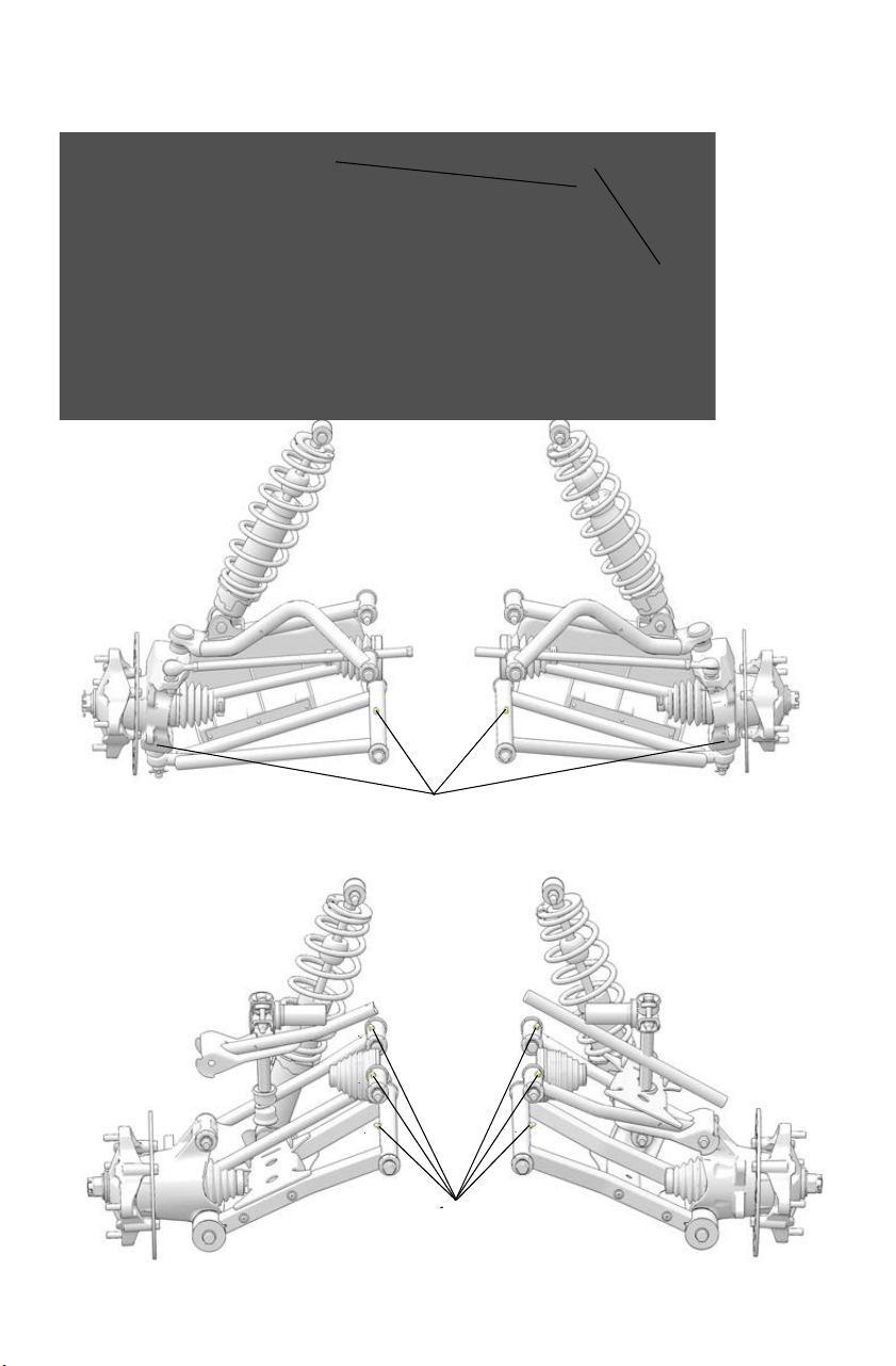
96
MAINTENANCE
Lubrication Guide
Front Prop Shaft Yoke
Prop Shaft Grease Fitting
Front Suspension
Grease Fittings
Rear Suspension
Grease Fittings
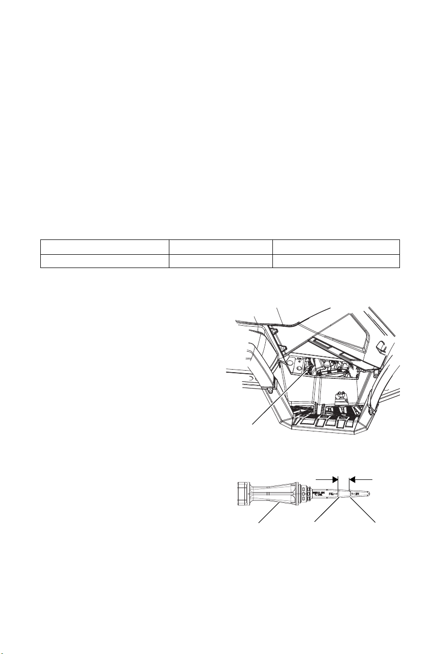
97
MAINTENANCE
Engine Oil
Oil Recommendations
Always change the oil filter whenever changing oil.
POLARIS recommends the use of POLARISPS-4 Full Synthetic 5W-50
4-cycle oil or a similar oil for this engine. Oil may need to be changed
more frequently if POLARIS oil is not used. Always use 5W-50 oil.
Follow the manufacturer's recommendations for ambient temperature
operation.
NOTICE: Mixing brands or using a non-recommended oil may cause serious
engine damage. Always use a recommended oil. Never substitute or
mix oil brands.
Oil Specifications
Oil Level
Access the oil dipstick and fill tube
from the right side of the Tractor.
A rising oil level between checks in
cool weather driving can indicate
contaminants such as gas or
moisture collecting in the
crankcase. If the oil level is over the
full/safe mark, change the oil
immediately.
1.
Position the vehicle on a level
surface.
2. Remove the dipstick. Wipe it
dry with a clean cloth.
3. Reinstall the dipstick
completely.
4. Remove the dipstick and check
the oil level. Maintain t
he oil
level in the safe
range. Do not
overfill.
Lubricant Capacity Drain Plug Torque
PS-4 5W-50 4-Cycle Oil 1.9 liters 19-23 N-m
Safe Add Oil
Safe Range
Dipstick
Dipstick
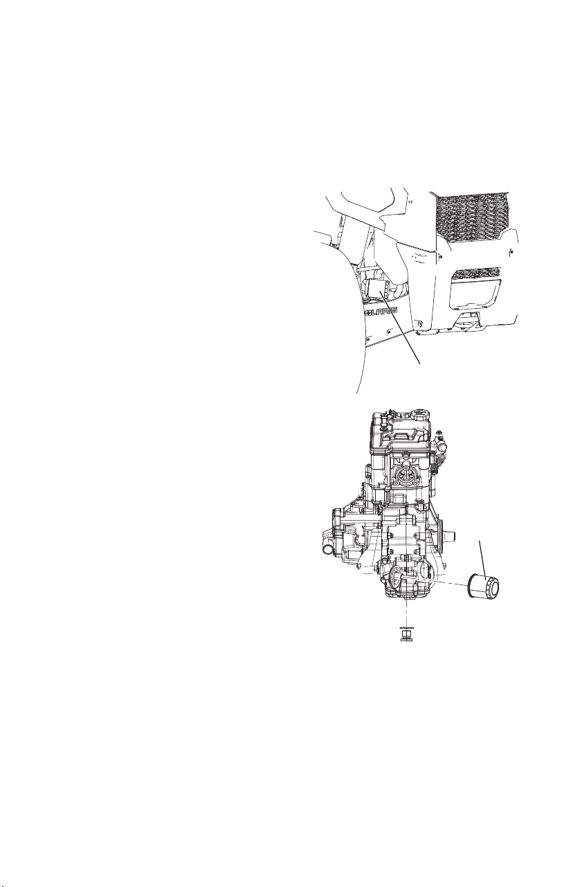
98
MAINTENANCE
Engine Oil
Oil and Filter Change
Always change the oil and filter at the intervals outlined in the Periodic
Maintenance Chart beginning on page 91. Always change the oil filter
whenever changing oil.
1. Position the vehicle on a level
surface.
2. Start the engine. Allow it to warm
up at idle for two to three
minutes.
3. Stop the engine.
4. Clean the area around the drain
plug.
5. Place a drain pan under the crank
case.
6. Remove the drain plug. Allow the
oil to drain completely.
CAUTION! Hot oil can cause burns to
skin. Do not allow hot oil to contact skin.
7. Install a new sealing washer on
the drain plug. The sealing
surfaces on drain plug and
crankcase should be clean and
free of burrs, nicks or scratches.
8. Reinstall the drain plug. Torque to
19-24 N-m.
9. Place shop towels beneath the oil
filter. Using an oil filter wrench
(available from your POLARIS
dealer), turn the filter counter-
clockwise to remove it.
10. Using a clean dry cloth, clean the
filter sealing surface on the
crankcase.
Oil
Filter
Drain Plug
Front View of the Engine
Oil Filter

99
MAINTENANCE
Engine Oil
Oil and Filter Change
11. Lubricate the o-ring on the new filter with a film of fresh engine oil.
Check to make sure the o-ring is in good condition.
12. Install the new filter and rotate it clockwise by hand until the filter
gasket contacts the sealing surface, then turn it an additional 3/4
turn.
13. Remove the dipstick.
14. Add 1.9 liters of recommended oil.
15. Place the transmission in PARK.
16. Lock the parking brake.
17. Start the engine. Allow it to idle for one to two minutes.
18. Stop the engine.
19. Check for leaks.
20. Check the oil level. Add oil as needed to bring the level to the upper
mark on the dipstick.
21. Dispose of used filter and oil properly.
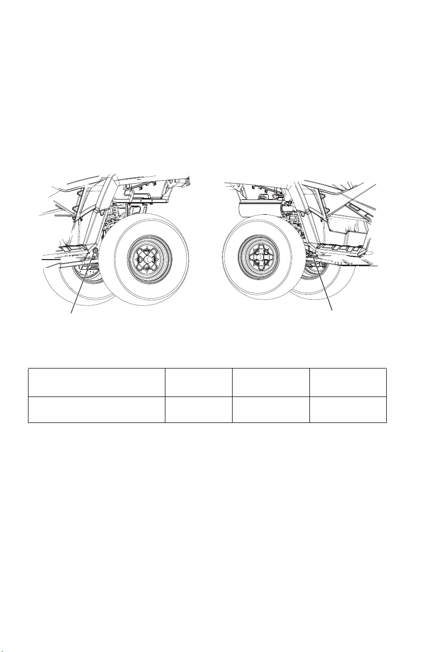
100
MAINTENANCE
Transmission Oil
Always check and change the transmission oil at the intervals outlined
in the Periodic Maintenance Chart beginning on page 91. Maintain the
oil level at the bottom of the fill plug hole threads. See page 145 for the
part numbers of POLARIS products.
The fill plug is located on the left side of the Tractor, under the rear
fender, behind the wheel. The drain plug is located on the right side of
the gearcase, on the right side of the Tractor, behind the wheel well.
Transmission Oil Recommendations
Lubricant Oil Change
Capacity
Fill Plug
Torque
Drain Plug
Torque
AGL Gearcase Lubricant &
Transmission Fluid
946 ml 27-34 N-m 27-34 N-m
Drain Plug
Check/Fill Plug

101
MAINTENANCE
Transmission Oil
Transmission Oil Level
1. Position the vehicle on a level
surface.
2. Remove the fill plug. Check
the oil level.
3. Add the recommended fluid as
needed to bring the level to
the bottom of the fill hole
threads.
4. Reinstall the fill plug. Torque
to specification.
Transmission Oil Change
1. Remove the fill plug.
2. Place a drain pan under the gearcase. Remove the drain plug. Allow
the oil to drain completely.
3. Clean and reinstall the drain plug. Torque to specification.
4. Add the proper amount of the recommended oil.
5. Reinstall the fill plug. Torque to specification.
6. Check for leaks.
7. Dispose of used oil properly.
Fill Level
Fill Plug
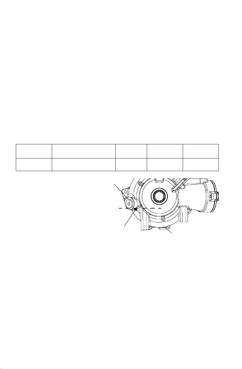
102
MAINTENANCE
Front Gearcase (Demand Drive) Fluid
Always check and change the demand drive fluid at the intervals out-
lined in the Periodic Maintenance Chart beginning on page 91. Maintain
the fluid level at the bottom of the fill hole threads. See page 145 for the
part numbers of POLARIS products.
Change the front gearcase fluid every 25 hours if the ADC unit is
exposed to extreme use. Extreme use includes any of the following:
• operation in ADC mode for prolonged periods
• constant ADC operation on hilly or mountainous terrain
• ADC is the primary mode of all-wheel-drive operation
TIP: If the front gearcase makes excessive noise during ADC operation, change
the demand drive fluid. If the noise continues, please see your POLARIS
dealer for service.
Fluid Recommendations
The fill plug is located on
the right side of the demand
drive unit. The drain plug is
located on the bottom right
side of the unit.
Fluid Level
1. Position the vehicle on a
level surface.
2. Place the transmission
in PARK.
3. Remove the fill plug.
4. Add the recommended demand drive fluid as needed to bring the
level to the bottom of the fill hole threads.
5. Reinstall the fill plug. Torque to 11-14 N-m.
Gearcase Lubricant Capacity Fill Plug
Torque
Drain Plug
Torque
Demand Drive
Unit
Demand Drive Fluid 275 ml 11-14 N-m 15 N-m
Drain Plug
Fill Plug
Fill Level

103
MAINTENANCE
Front Gearcase (Demand Drive) Fluid
Fluid Change
1. Position the vehicle on a level surface. Remove the fill plug. Place a
drain pan under the demand drive unit.
2. Remove the drain plug. Allow the fluid to drain completely.
3. Clean and reinstall the drain plug. Torque to 15 N-m.
4. Add the recommended fluid.
5. Reinstall the fill plug. Torque to 11-14 N-m.
6. Check for leaks. Discard used oil properly.
Cooling System
The engine coolant level is controlled, or maintained, by the recovery
system. The recovery system components are the recovery bottle, the
radiator filler neck, the radiator pressure cap and the connecting hose.
As coolant operating temperature increases, the expanding (heated)
excess coolant is forced out of the engine, past the pressure cap, and into
the recovery bottle. As engine coolant temperature decreases the
contracting (cooled) coolant is drawn back up from the bottle, past the
pressure cap, and into the radiator.
Some coolant level drop on new vehicles is normal as the system is
purging itself of trapped air. Check the coolant level and maintain as
recommended by adding coolant to the recovery bottle.
POLARIS recommends the use of POLARIS Antifreeze 50/50 Premix.
This antifreeze is already premixed and ready to use. Do not dilute with
water. See page 145 for the part numbers of POLARIS products.
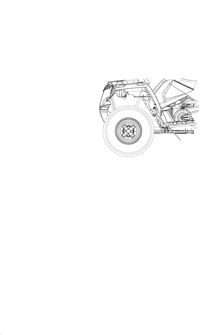
104
MAINTENANCE
Cooling System
Recovery Bottle Coolant
Some coolant level drop on new machines is normal, as the system is
purging itself of trapped air. Add coolant as needed.
Check the coolant level in the radiator any time the recovery bottle has
run dry. Add coolant as needed.
1. Check the coolant level
when the fluid is cool.
2. Remove the left side panel.
See page 113.
3. View the coolant level.
Maintain the coolant level
between the minimum and
maximum marks on the
bottle (when the fluid is
cool).
4. Add coolant as needed.
5. Reinstall the side panel.
Recovery
Bottle
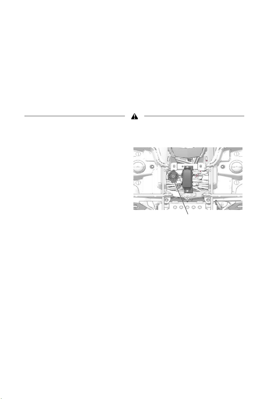
105
MAINTENANCE
Cooling System
Radiator Coolant
To ensure that the coolant maintains its ability to protect the engine, we
recommend that the system be completely drained every five (5) years
and fresh Antifreeze 50/50 Premix added.
Any time the cooling system has been drained for maintenance or repair,
replace the coolant with fresh Antifreeze 50/50 Premix.
If the recovery bottle has run dry, check the level in the radiator. Add
coolant as needed.
Escaping steam can cause severe burns. Never remove the pressure cap while
the engine is warm or hot.
1. Open the front box cover.
2. Remove the access panel
screws. Squeeze the outer
edges of the panel inward to
remove the panel.
3. Remove the pressure cap.
4. Using a funnel, slowly add
coolant through the radiator
filler neck.
5. Reinstall the pressure cap.
Use of a non-standard pressure cap will not allow the recovery
system to function properly. Contact your dealer for the correct
replacement part.
6. Reinstall the access panel and secure the front box cover.
Radiator Cap

106
MAINTENANCE
Brake Fluid
Check brake fluid levels for both brake systems before each ride.
Always maintain brake fluid at the recommended level. Do not overfill.
The brakes should feel firm when they’re applied. Spongy or weak
brakes may indicate a fluid leak or low fluid level. A low fluid level
may also mean that brake pads are worn and need to be replaced. Do not
operate the vehicle with spongy or weak brakes. See your dealer for
service.
Operating the Tractor with a spongy brake can result in loss of braking, which
could cause an accident. Never operate the Tractor with spongy-feeling brakes.
If the fluid level is low add DOT 4 brake fluid only. See page 145 for the
part numbers of POLARIS products.
An over-full master cylinder may cause brake drag or brake lock-up, which could
result in serious injury or death. Maintain brake fluid at the recommended level.
Do not overfill.
Under normal operation, the diaphragm extends into the reservoir as
fluid level drops. If the fluid level is low and the diaphragm is not
extended, a leak is likely and the diaphragm should be replaced. To
ensure proper diaphragm operation, always fill the reservoir as needed
whenever the cover is loosened or removed. Do not overfill.
Never store or use a partial bottle of brake fluid. Brake fluid is hygroscopic,
meaning it rapidly absorbs moisture from the air. The moisture causes the
boiling temperature of the brake fluid to drop, which can lead to early brake fade
and the possibility of accident or severe injury. After opening a bottle of brake
fluid, always discard any unused portion.
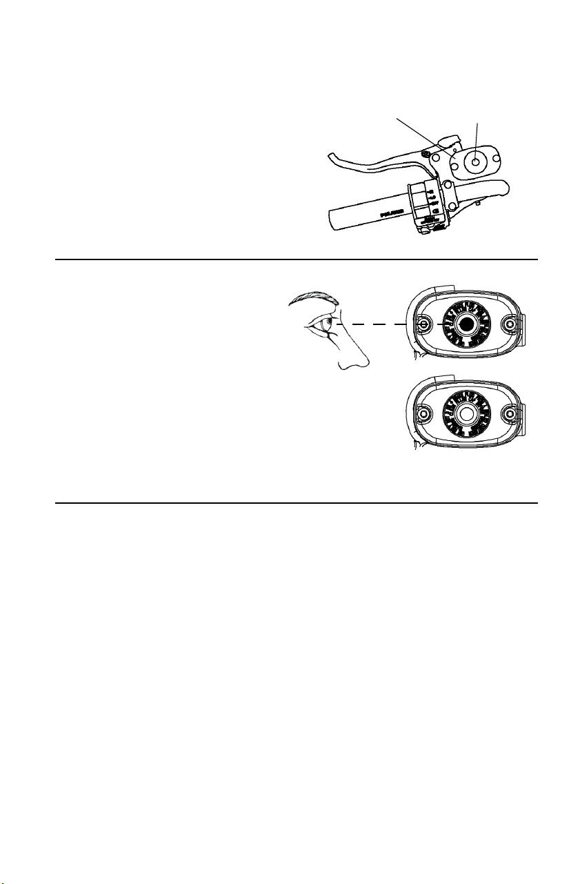
107
MAINTENANCE
Brake Fluid
Hand Brake
The master cylinder is located
on the left handlebar. Maintain
the fluid level 6 mm below the
top edge of the master
cylinder. Do not overfill.
1. Position the vehicle on a
level surface. Make sure
the handlebars are straight.
2. View the fluid level
through the indicator
window (eye) on the top of
the master cylinder. The
eye will appear dark when
the fluid level is full. When
fluid is low, the eye will be
clear.
3. Add the recommended fluid as needed. Do not overfill.
Master
Cylinder
Indicator
Window
Full
Low
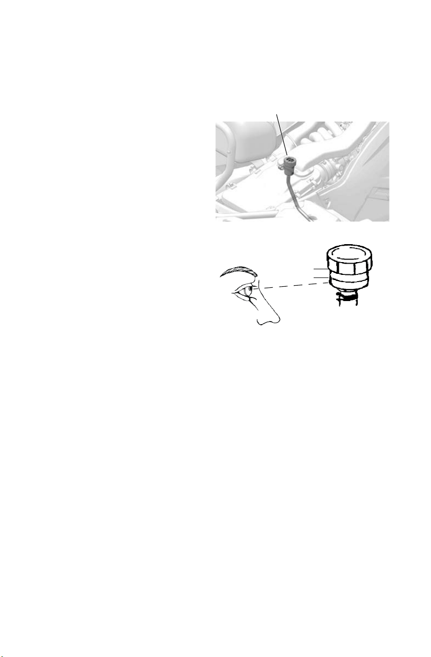
108
MAINTENANCE
Brake Fluid
Foot Brake
Check the brake fluid level
frequently for the foot brake
system. The foot brake fluid
reservoir is located under the seat.
1. Position the vehicle on a level
surface.
2. Remove the seat.
3. View the fluid level in the
reservoir.
4. Remove the cap and add the
recommended fluid as
needed.
5. Maintain the fluid level
between the minimum and
maximum marks. Do not
overfill.
6. Reinstall the reservoir cap.
7. Reinstall the seat.
Minimum
Maximum
Brake Fluid
Reservoir
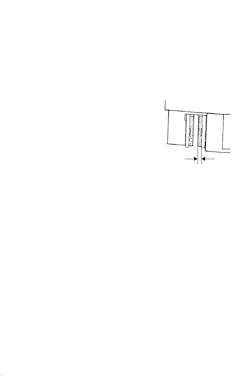
109
MAINTENANCE
Brakes
The front and rear hand brakes are hydraulic disc brakes, activated by
moving the single brake lever toward the handlebar. The auxiliary foot
brakes are also hydraulic disc brakes. All brakes are self-adjusting.
Brake Inspections
Inspect brake components at the intervals outlined in the Periodic
Maintenance Chart beginning on page 91. Check more often if brakes
are used heavily under normal operation.
1. Always keep brake fluid at an adequate
level. See page 106.
2. Inspect hydraulic hoses for leaks, wear
or damage. Replace worn or damaged
hoses promptly.
3. Check the brakes for excessive travel
or spongy feel.
4. Check the friction pads for wear,
damage and looseness. Replace the
pads when the friction material is worn
to 0.762 mm.
5. Check the security and surface condition of the disc. Clean any
grease using a recommended brake cleaner or alcohol. Do not use
spray lubricants or other petroleum-based products. If you discover
any damage (cracks, excessive corrosion, warping) see your dealer
for service before operating.
0.762 mm
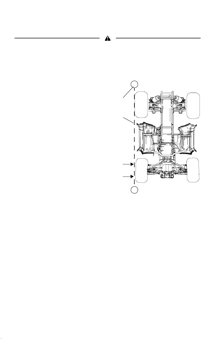
110
MAINTENANCE
Toe Alignment
Do not attempt to adjust alignment. All steering adjustments should be
performed by an authorized POLARIS dealer.
Use the following procedure to check the toe alignment of the vehicle.
The recommended toe alignment is 3-6 mm toe out.
1. Position the vehicle on a
level surface.
2. Place the handlebars in a
straight-ahead position.
3. Tie a length of string
between two stands as
shown in the illustration.
Position the stands so
that the string is flush
with the side of the rear
tire.
TIP: If available, you may use a
long straight-edge instead
of string.
4. Measure the distance
from the string to the
rim at the front (1) and
rear (2) of the front rim.
The rear measurement should be 2-3 mm more than the front
measurement on each side of the vehicle to obtain the
recommended 3-6 mm toe out alignment.
5. Repeat the measurement procedure on the other side of the vehicle.
6. If you discover improper alignment, see your POLARIS dealer for
service.
String
Stand
2
1
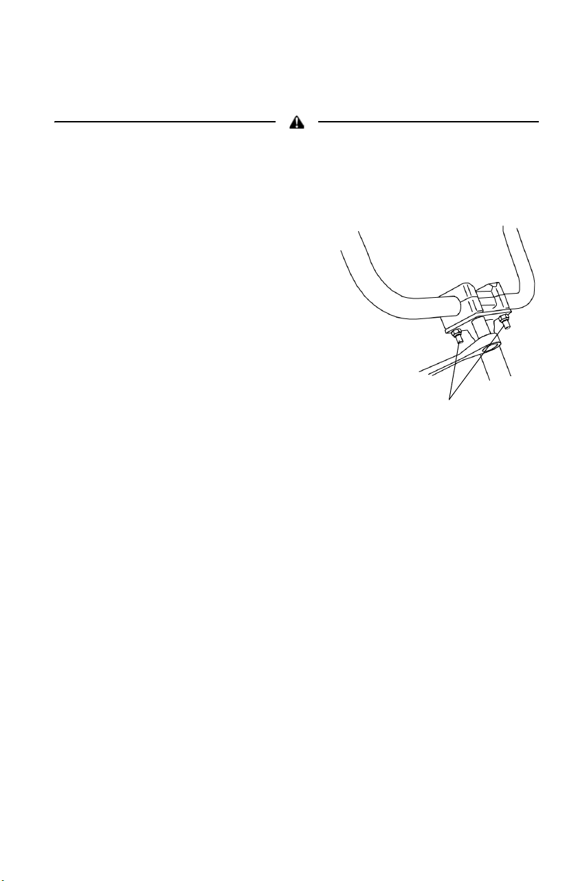
111
MAINTENANCE
Handlebar Adjustment
The handlebars can be adjusted for rider preference.
Improper adjustment of the handlebars or incorrect torquing of the adjuster
block tightening bolts can cause limited steering or loosening of the handlebars,
resulting in loss of control. Follow the adjustment procedures exactly, or see
your POLARIS dealer for service.
1. Remove the upper headlight pod.
2. Loosen the four handlebar bolts.
3. Adjust the handlebar to the desired
height.
4. Be sure the handlebars do not
contact the gas tank or any other
part of the machine when turned
fully to the left or right.
5. Torque the front two bolts to 14-17
N-m, then torque the rear two
bolts. A gap of up to 3 mm will
remain at the rear of the clamp
blocks.
14-17 N-m
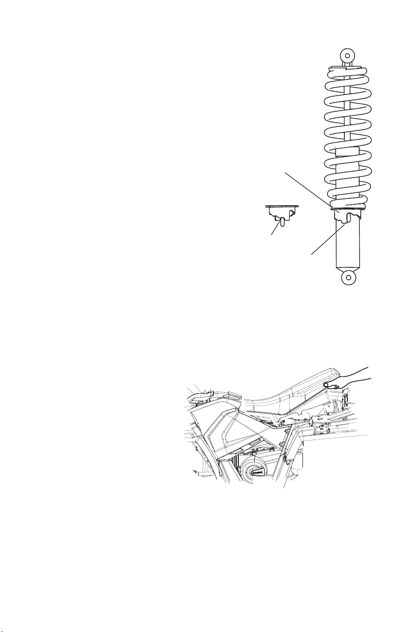
112
MAINTENANCE
Steering Assembly
Check the steering assembly of the vehicle
periodically for loose nuts and bolts. If
loose nuts and bolts are found, see your
POLARIS dealer for service before
operating the vehicle.
Rear Spring
The rear shock absorber spring is adjusted
by rotating the adjuster either clockwise or
counter-clockwise to increase or decrease
spring tension.
Front Spring
The front shock absorber spring is adjusted
by rotating the cam either clockwise or
counter-clockwise to increase or decrease
spring tension.
Power Steering Unit
If your model is equipped with power steering, frequently clean the
areas around and on the power steering unit to allow proper cooling.
Clean these areas thoroughly.
Seat Removal
1. Grasp one side of the seat
near the rear edge.
2. Pull upward abruptly to
disengage the under-seat
fasteners.
3. Remove the seat.
High
Tension
Low
Tension
Cam
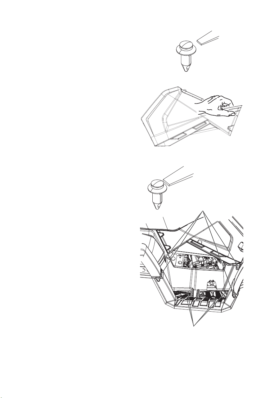
113
MAINTENANCE
Side Panel Removal
1. Remove the seat. See page
112.
2. Use a flat screwdriver to
remove the plastic rivets
securing the side panel.
3. Grasp the rear of the side
panel near the rear cab. With
a firm motion, pull the side
panel outward to disengage
the side panel from the
grommets.
4. Pull the panel outward and
rearward to remove it.
Footwell Removal (570/450 HO)
1. Remove the four screws on the
bottom of the footwell.
2. Use a flat screwdriver to remove
the plastic rivets securing the
footwell to the fenders.
3. Remove the footwell.
Step 2
Step 3
Torx Head
Screws
Plastic Rivets
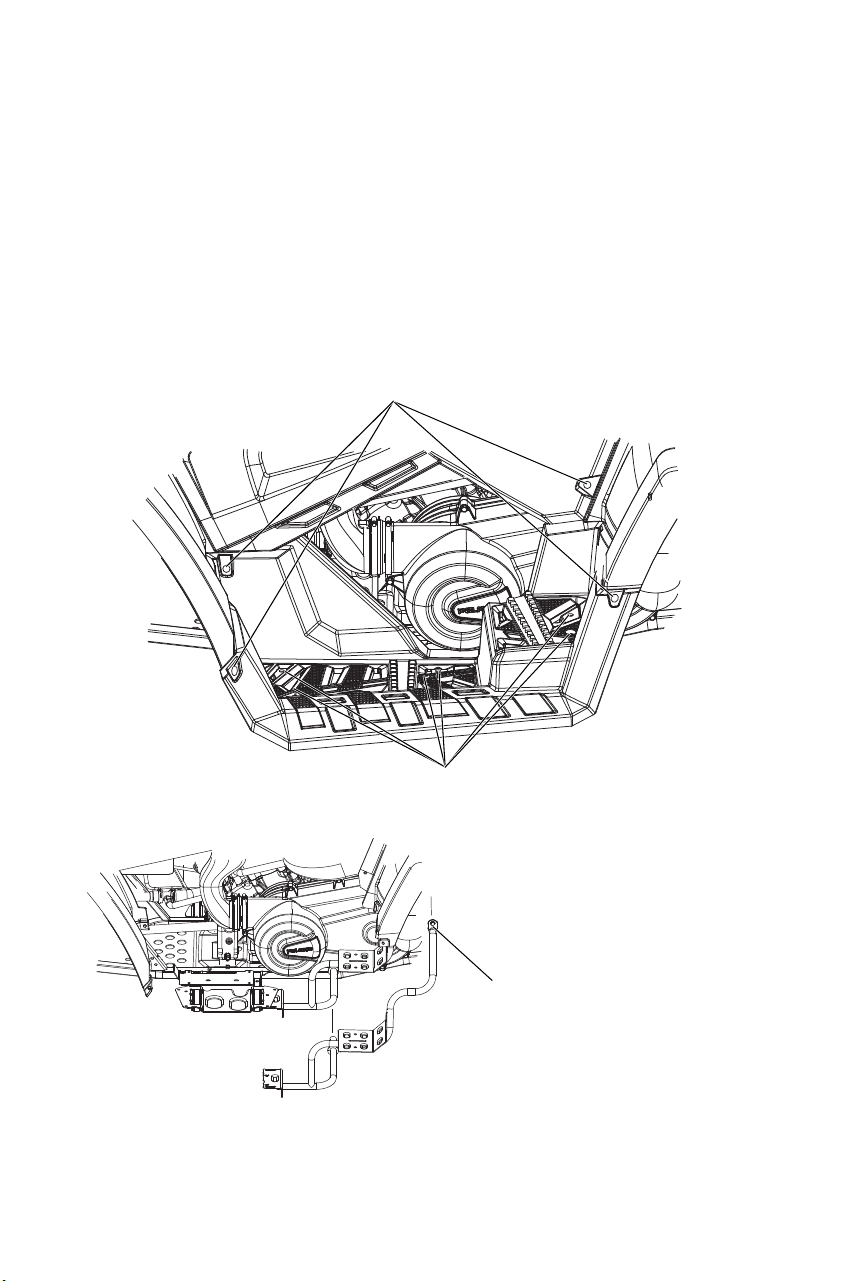
114
MAINTENANCE
Footwell/Footwell Support Removal (if
equipped)
1. Remove the six screws on the bottom of the footwell.
2. Use a flat screwdriver to remove the plastic rivets securing the
footwell to the fenders.
3. Remove the footwell.
4. If removing the footwell support is necessary to access the clutch
cover, remove the hex flange screw securing the support to the
frame.
Torx Head
Screws (6)
Plastic Rivets (4)
Footwell Support
Hex Flange Screw
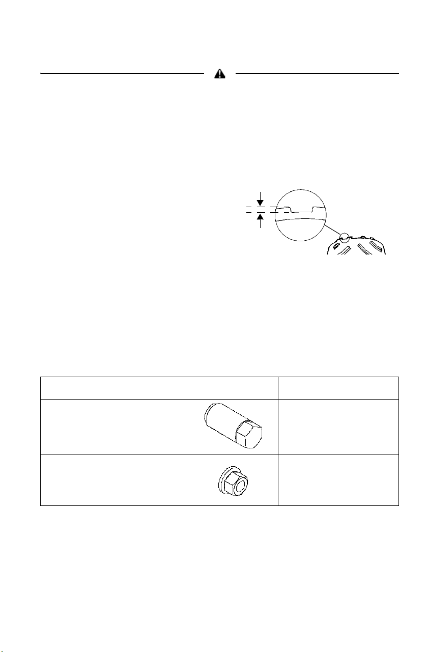
115
MAINTENANCE
Tires
Operating your vehicle with worn tires, improperly inflated tires, non-standard
tires or improperly installed tires will affect vehicle handling and could cause an
accident. Always follow all tire maintenance procedures as outlined in this
manual and on the labels on the vehicle. Always use original equipment size
and type when replacing tires.
Refer to the specifications section beginning on page 146 for
recommended tire type, size and pressure.
Tire Tread Depth
Always replace tires
when tread depth is
worn to 3 mm or less.
Front Wheel Hub Tightening
Front wheel bearing tightness and spindle nut retention are critical
component operations. All service must be performed by your
authorized POLARIS dealer.
Wheel Nut Torque Specifications
Check the wheel nut torques occasionally and when they've been
loosened for maintenance service.
Nut Type Nut Torque
Lug Nut 41 N-m
PLUS 1/4 TURN
2-Piece Flange Nut 37 N-m
3 mm

116
MAINTENANCE
Tires
Wheel Removal/Installation
1. Position the vehicle on a
level surface.
2. Place the transmission in
PARK.
3. Loosen the wheel nuts
slightly.
4. Elevate the end of the vehicle. See
page 91.
5. Remove the wheel nuts.
6. Remove the wheel.
7. Place the wheel on the hub.
8. Install the wheel nuts finger tight.
9. Lower the vehicle to the ground.
10. Torque the wheel nuts to specification. See torque chart on page
115.
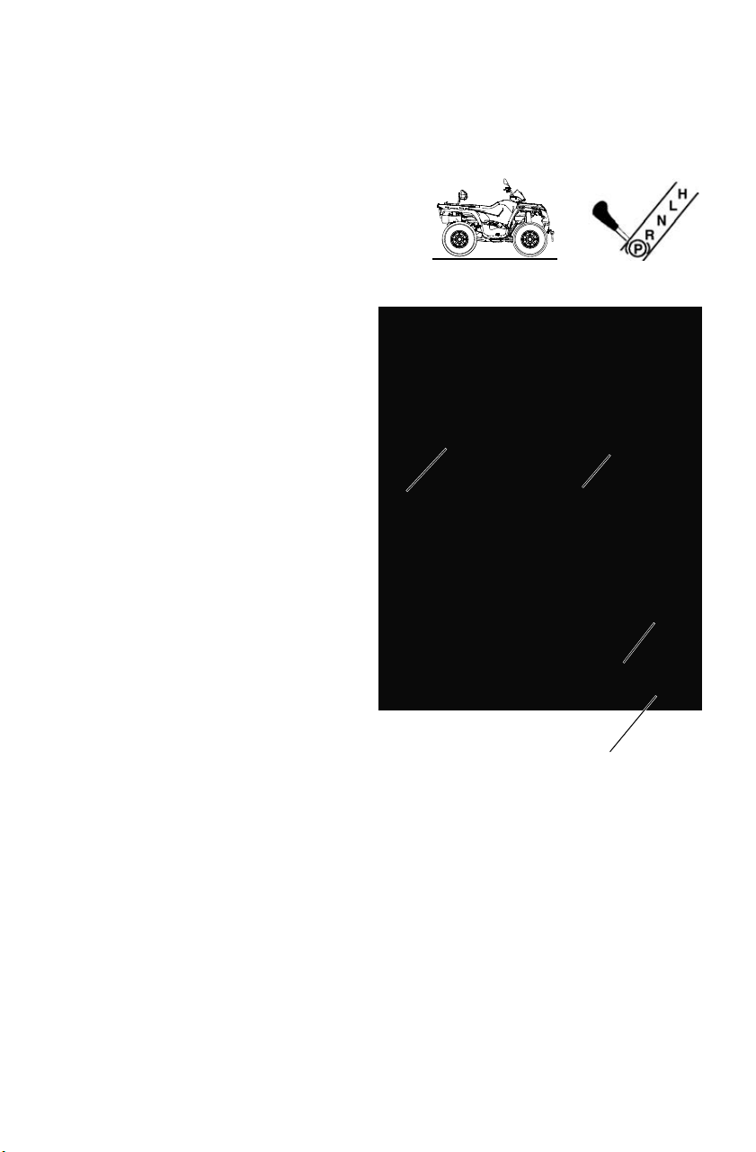
117
MAINTENANCE
Air Filter
Always clean and replace the air and breather filters at the intervals
outlined in the Periodic Maintenance Chart beginning on page 91.
1. Position the vehicle on a level
surface.
2. Place the transmission in PARK.
3. Remove the seat.
4. Release the air box cover
clips, and remove the air
box cover.
5. Loosen the clamp and
remove the filter.
6. Remove the fabric type
pre-filter from the main
filter. Wash the pre-filter
in soapy water, then rinse
and let dry.
7. Reinstall the pre-filter
over the main filter. Install
a new main filter if
needed.
8. Reinstall the filter into the
air box and tighten the
clamp. Do not overtighten
the clamp, as filter
damage could occur.
9. Reinstall the air box cover
and the seat.
Breather Line
Pre-Filter
Main Filter
Breather
Valve

118
MAINTENANCE
Breather Filter/Hose
The breather valve is on the hose that runs between the engine and air
box. See illustration on page 117.
1. Remove the left side panel. See page 113.
2. Remove the hose clamps from the valve and pull the valve out of
the hoses.
3. Inspect the valve for debris. Blow gently through the valve to check
for clogging. Replace a damaged or clogged valve.
4. Check the hoses for cracks, deterioration, abrasion, or leaks.
Replace as needed.
5. Reinstall the valve and hose clamps.
NOTICE: Operation of your vehicle without a breather filter can cause engine
damage. Always reinstall the breather valve after removing it for
service.
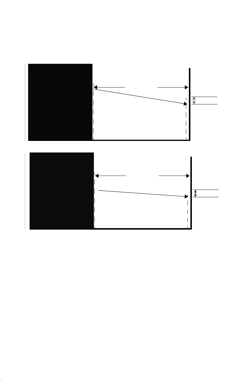
119
MAINTENANCE
Lights
High Beam Adjustment
The headlight beam can be adjusted slightly.
1. Position the vehicle on a level surface. The headlight should be
approximately 7.6 m from a wall.
2. Place the transmission in PARK.
3. Measure the distance from the floor to the center of the headlight
and make a mark on the wall at the same height. Include rider
weight on the seat when measuring.
7.6 m
5 cm
X
X
7.6 m
5 cm
X
X
Models with pod headlight
Models without pod headlight
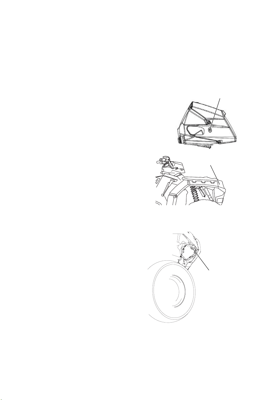
120
MAINTENANCE
Lights
High Beam Adjustment
4. Start the engine.Turn the headlight switch to high beam.
5. Observe the headlight aim on the wall. The most intense part of the
headlight beam should be 5 cm below the mark on the wall.
6. 570 Premium: The adjustment
screw is located on the right side
of the headlight pod. To adjust
the beam, loosen the screw.
Adjust the headlamp to the
desired position, then tighten the
screw.
7. 570/570 EPS/570 X2: The
adjustment knob is located on
the right side of the headlight
pod. Adjust the beam to the
desired position by turning the
knob either clockwise or
counter-clockwise.
8. All Models: Tighten or loosen
the three (3) headlight screws to
adjust the beam.
Low Beam Adjustment
The low beam can be adjusted slightly
upward or downward.
1. Loosen the Phillips screw located
at the rear of the headlamp.
2. Tilt the headlamp upward or
downward.
3. Tighten the screw.
570 Premium
Adjustment Screw
Screws
Phillips
Screw
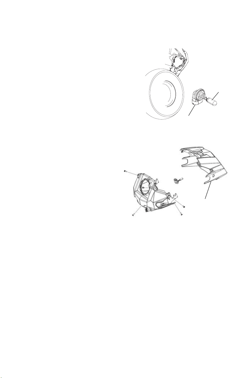
121
MAINTENANCE
Lights
Lower Headlamp Replacement
1. Turn the back of the headlight
harness counter-clockwise and
pull the harness assembly away
from the headlight assembly.
2. Remove the headlamp and install
the new headlamp.
3. Reinstall the harness assembly
into the headlight assembly.
4. Turn the headlight harness
clockwise to secure the headlamp.
Headlight Housing Replacement (570 Premium)
1. Remove the seven (7)
headlight pod screws.
2. Pull the pod cover forward.
3. Unplug the headlamp from
the wiring harness.
4. Use a small screwdriver to
remove the o-rings from the
headlight mounting tabs.
5. Pull the headlight housing
up from the bracket for
removal.
6. Reverse the steps to install the new housing and reassemble the pod.
Harness
Lamp
Headlight
Housing

122
MAINTENANCE
Lights
Headlight Housing Replacement (570/570 EPS/570 X2)
1. Remove the two screws on the lower front corners of the headlight
pod.
2. Lift the pod slightly while depressing the tabs at the rear of the pod.
3. Lift the pod cover and disconnect the speedometer harnesses from
the speedometer.
4. Unplug the headlamp from the wiring harness.
5. Use a small screwdriver to remove the o-rings from the headlight
mounting tabs.
6. Pull the headlight housing up to release it from the locking tabs.
7. Lift the adjusting knob up to remove it from the locking tabs.
8. Carefully pull the assembly up
and out of the pod.
9. Reverse the steps to install the
new housing and reassemble
the pod. The distance from the
headlamp parting line to the
end of the adjustment knob
stop is 13 cm.
10. Adjust the headlight aim by
turning the adjusting knob.
13 cm

123
MAINTENANCE
Lights
Poor lighting can result in loss of control or an accident. Lights become dirty
during normal operation. Wash the headlights and taillights frequently.
Hot components can cause serious burns to skin. Do not service the headlamps
until they've cooled.
Headlight/Parking Light Lamp Replacement
When servicing a halogen lamp, do
not touch the lamp with bare fingers.
Oil from your skin leaves a residue,
causing a hot spot that will shorten
the life of the lamp. Hold the plastic
part of the lamp.
1. Place the transmission in PARK.
2. Reach under the front bumper area
to locate the lighting connectors.
3. Parking Light Lamp: Disconnect
the harness connector. Turn the
socket counter-clockwise 1/8 turn
and remove the lamp assembly.
Pull the lamp straight out to
remove it from the socket.
4. Headlight Lamp: Disconnect the
harness connector. Remove the
rubber cover from the back of the
headlight. Press and turn the
locking collar counter-clockwise
(left headlight) or clockwise (right
headlight) to release the lamp
assembly.
5. Install the new lamp. Apply a
small amount of dielectric grease
to the lamp socket or terminals.
6. Reverse all steps to reassemble
components.
Parking Light
Collar
Socket
Headlamp
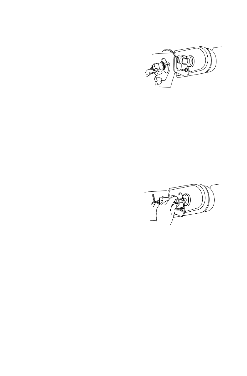
124
MAINTENANCE
Lights
Taillight Lamp Replacement
1. Place the transmission in PARK.
2. Rotate the taillight socket counter-
clockwise to remove it.
3. Remove the lamp.
4. Apply dielectric grease to the socket.
5. Install the new lamp. Test the lamp for
proper operation.
6. Reinstall all componenets in reverse order.
Front Turn Signal Replacement
If a front turn signal light becomes inoperable, the lamps cannot be
replaced. Replace the entire signal lamp assembly.
Rear Turn Signal Lamp
Replacement
1. Place the transmission in PARK.
2. Rotate the turn signal socket counter-
clockwise.
3. Remove the lamp.
4. Apply dielectric grease to the socket.
5. Install the new lamp. Test the lamp for proper operation.
6. Reinstall all components in revers order.
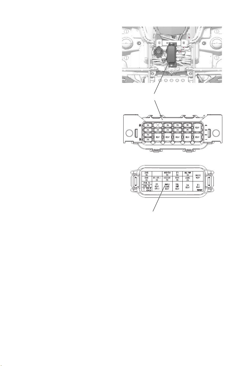
125
MAINTENANCE
Fuse Replacement
If the engine stops or will not
start, or if you experience other
electrical failures, a fuse may
need replacement. Locate and
correct any short circuits that
may have caused the blown fuse,
then replace the fuse. Spare fuses
are provided in a compartment on
the top of the access door.
1. Open the front box cover.
2. Remove the access panel.
See page 105.
3. Remove fuse box cover.
4. Remove the suspect fuse
from the fuse panel. If the
fuse is blown, install a new
fuse with the same amperage.
5. Secure the fuse box cover
and access panel.
6. Secure the front box cover.
Fuse Box
Label Inside Fuse Box Cover

126
MAINTENANCE
Spark Plugs
Spark Plug Recommendations
Refer to the specifications section beginning on page 146 for the
recommended spark plug type and gap for your vehicle. Torque spark
plugs to specification.
Spark Plug Inspection
Spark plug condition is indicative of engine operation. Check the spark
plug firing end condition after the engine has been warmed up and the
vehicle has been driven at higher speeds. Immediately check the spark
plug for correct color.
Normal Spark Plug
The normal insulator tip is tan or brown. There will be few combustion
deposits. The electrodes are not burned or eroded. This indicates the
proper type and heat range for the engine and the service.
The tip should not be white. A white insulator tip indicates overheating,
caused by use of an improper spark plug or incorrect throttle body
adjustments.
Wet Fouled Spark Plug
The wet fouled insulator tip is black. A damp oil film covers the firing
end. There may be a carbon layer over the entire nose. Generally, the
electrodes are not worn. General causes of fouling are excessive oil
consumption, use of non-recommended oil or incorrect throttle body
adjustments.
Plug Condition Torque Specification
New Spark Plug 12 N-m
Previously Installed Spark Plug 12 N-m
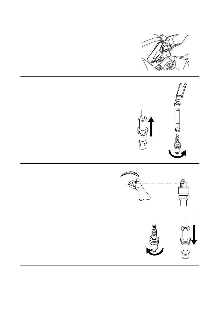
127
MAINTENANCE
Spark Plugs
Spark Plug Removal
1. Remove the left side panel.
See page 113.
2. Remove the spark plug cap.
3. Use the spark plug wrench
to remove the spark plug.
Turn the plug counter-
clockwise to remove it.
4. Inspect the electrodes for
wear and carbon buildup.
Replace worn or fouled
plugs. Verify that the gap is
at specification before
installation.
5. Reinstall the spark plug.
Torque to specification. See
page 126.
6. Reinstall the spark plug cap.
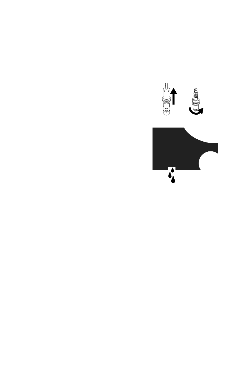
128
MAINTENANCE
Vehicle Immersion
If your vehicle has been totally submerged in water and it's impossible
to have it serviced before further operation, perform the following
procedure.
NOTICE: If the vehicle stops while fully submerged, major engine damage can
result if the machine is not thoroughly inspected. Take the vehicle to
your dealer before starting the engine.
1. Move the vehicle out of the water.
2. Remove the spark plug.
3. Drain any water found in the air box.
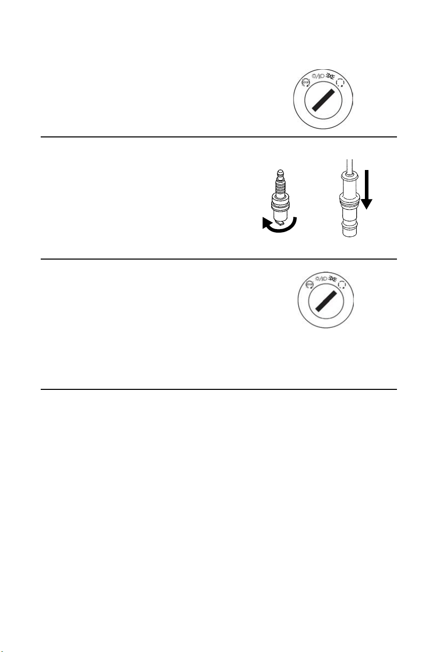
129
MAINTENANCE
Vehicle Immersion
4. Turn the ignition key past the
PARKING LIGHTS position to
engage the starter. Engage the
starter for only 2-3 seconds.
5. Dry the spark plug. Reinstall the
plug or install a new plug.
6. Torque to specification. See page
126.
7. Attempt to start the engine. If
necessary, repeat the drying
procedure.
8. Have the vehicle serviced by
your dealer promptly, whether
you succeed in starting it or not.
9. If water has been ingested into the PVT, follow the procedure on
page 133 for drying out the PVT.
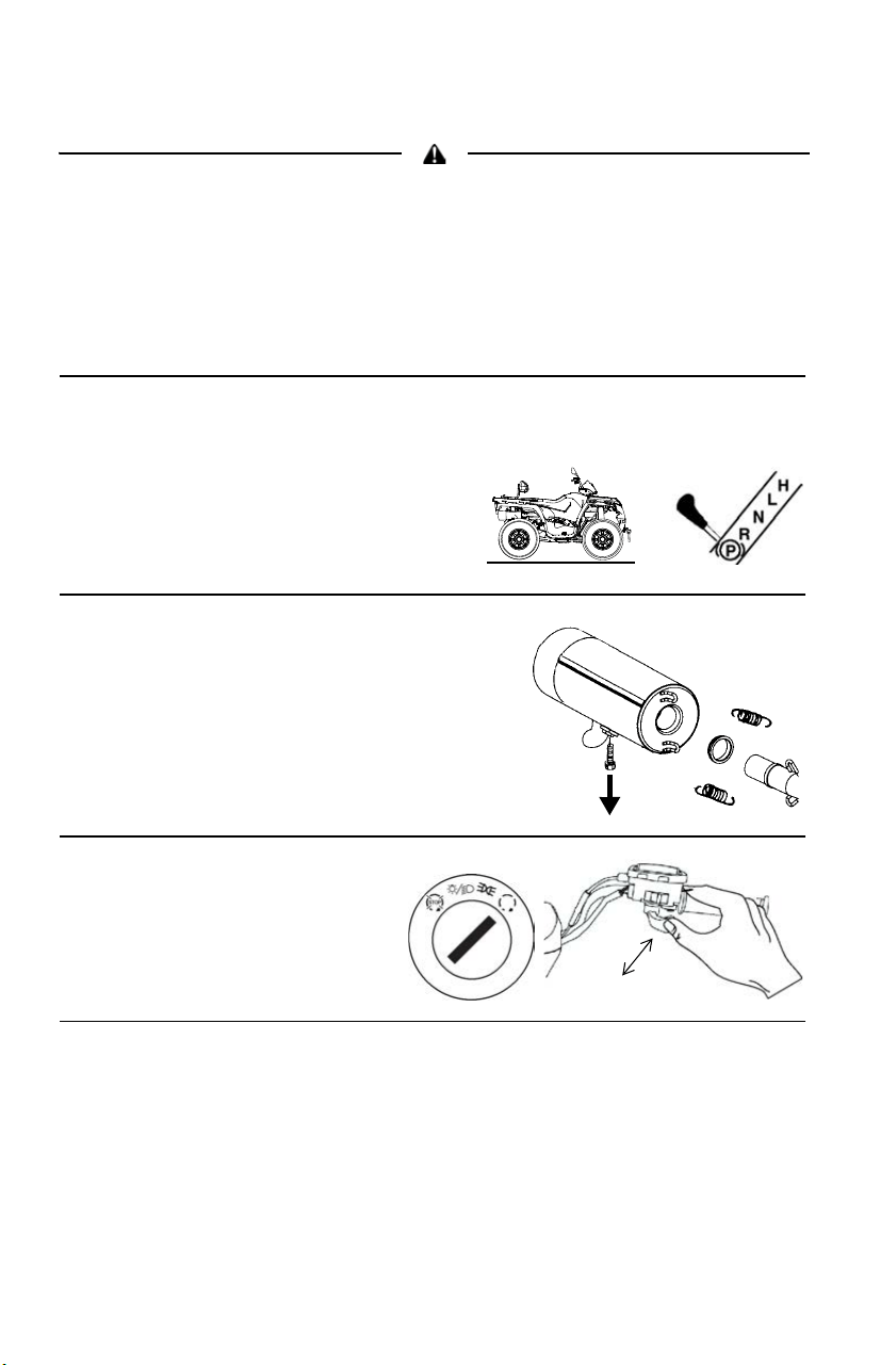
130
MAINTENANCE
Spark Arrester
Failure to heed the following warnings while servicing the spark arrester could
result in serious injury or death. Never run the engine in an enclosed area.
Remove any combustible materials from the area. Wear eye protection and
leather work gloves. Do not stand behind or in front of the vehicle while purging.
Never go under the vehicle while it's inclined.
The exhaust system can get extremely hot. Do not perform service on the spark
arrester while the system is hot. Allow components to cool sufficiently before
proceeding.
Occasionally, the spark arrester may accumulate carbon, which can
restrict the exhaust if left unattended. Purge the spark arrester.
1. Position the vehicle on a level
surface.
2. Place the transmission in PARK.
3. Remove the arrester
clean-out plug from the
bottom of the muffler.
4. Start the engine.
5. Quickly squeeze and
release the throttle lever
several times to purge
carbon from the system.
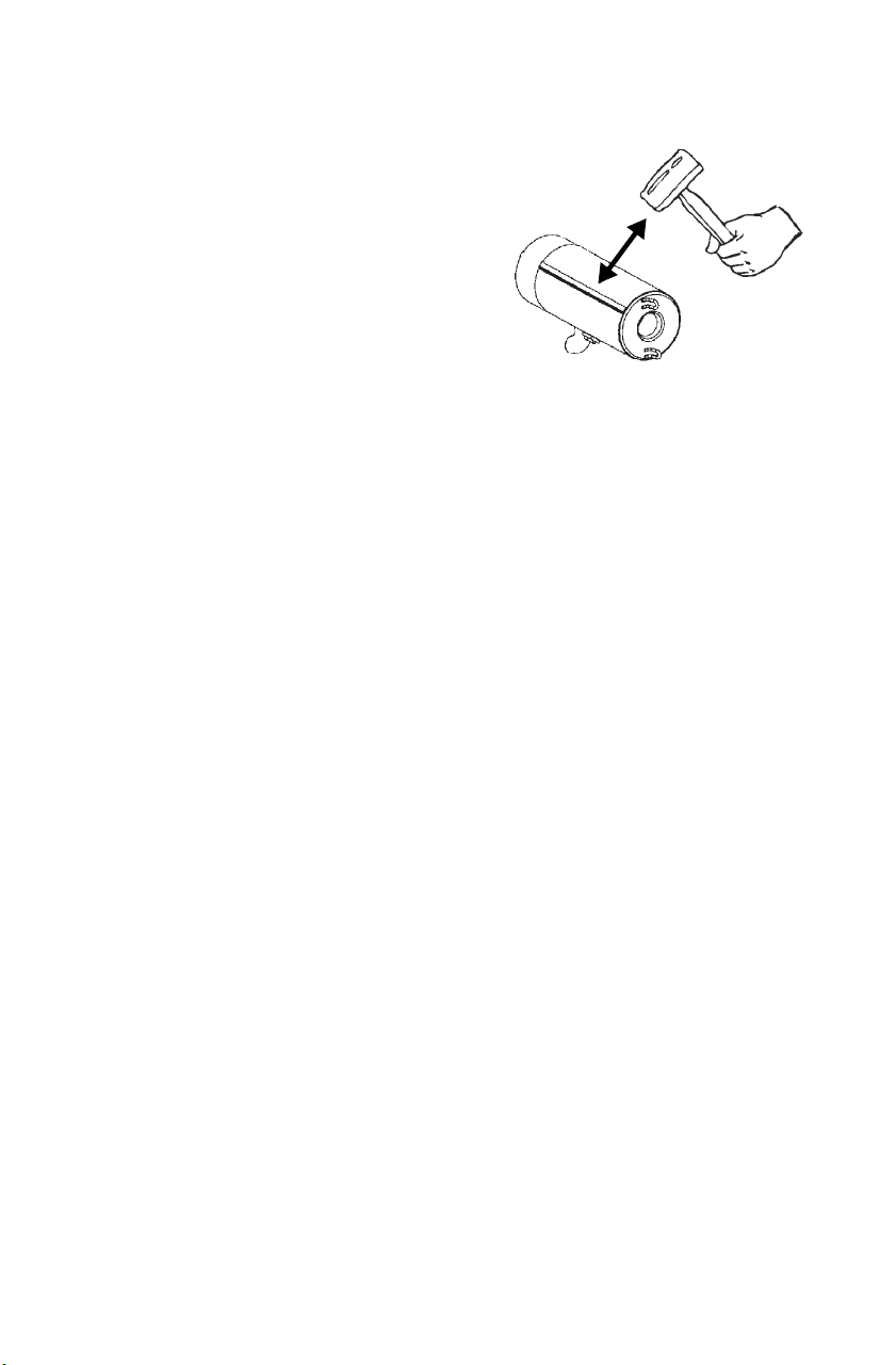
131
MAINTENANCE
Spark Arrester
6. If carbon comes out of the
exhaust, cover or plug the
exhaust outlet. Wear protective
gloves.
7. Lightly tap on the exhaust pipe
with a rubber mallet while
repeating step 5.
8. If particles are still suspected to
be in the muffler, elevate the
rear of the vehicle 30 cm higher
than the front. See page 91. Block the front wheels to prevent
rolling.
9. Place the transmission in PARK. Repeat steps 5 to 7 until no more
particles are expelled.
10. Stop the engine. Allow the arrester to cool.
11. Reinstall the arrester plug and remove the exhaust outlet cover or
plug.

132
MAINTENANCE
PVT System
Do not modify any component of the PVT system. Doing so may reduce its
strength so that a failure may occur at a high speed. The PVT system has been
precision balanced. Any modification will cause the system to be out of balance,
creating vibration and additional loads on components.
The PVT system rotates at high speeds, creating large amounts of force on
clutch components. Extensive engineering and testing has been conducted to
ensure the safety of this product. However, as the owner, you have the following
responsibilities to make sure this system remains safe:
• Always follow all recommended maintenance procedures. Always look for
and remove debris inside and around the clutch and vent system when
replacing the belt.
• See your dealer as outlined in the owner's manual.
• This PVT system is intended for use on POLARIS products only. Do not
install it in any other product.
• Always make sure the PVT housing is securely in place during operation.
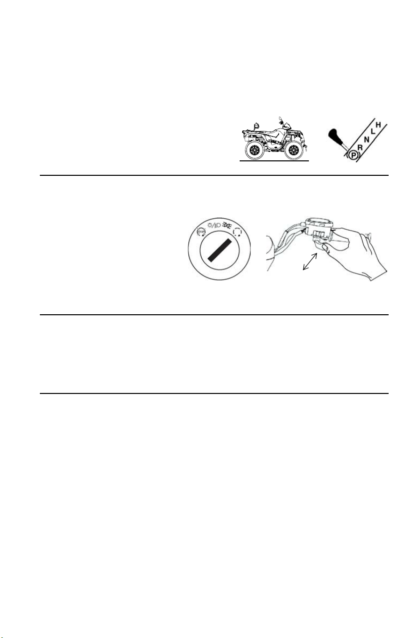
133
MAINTENANCE
PVT System
PVT Drying
There may be some instances when water is accidently ingested into the
PVT system. Dry it out before operating.
1. Position the vehicle on a level
surface.
2. Place the transmission in PARK.
3. Remove the drain plug. Allow the water to drain completely.
Reinstall the drain plug.
4. Start the engine.
5. Apply varying throttle
for 10-15 seconds to
expel the moisture and
air-dry the belt and
clutches. Do not hold
the throttle wide open for more than 10 seconds.
6. Allow the engine RPM to settle to idle speed, then shift the
transmission to the lowest available range.
7. Test for belt slippage. If the belt slips, repeat the process.
8. Take the vehicle to your dealer for service as soon as possible.

134
MAINTENANCE
Battery
Battery electrolyte is poisonous. It contains sulfuric acid. Serious burns can
result from contact with skin, eyes or clothing.
Antidote:
External: Flush with water.
Internal: Drink large quantities of water or milk. Follow with milk of magnesia,
beaten egg, or vegetable oil. Call physician immediately.
Eyes: Flush with water for 15 minutes and get prompt medical attention.
Batteries produce explosive gases. Keep sparks, flame, cigarettes, etc. away.
Ventilate when charging or using in an enclosed space. Always shield eyes
when working near batteries. KEEP OUT OF REACH OF CHILDREN.
Your vehicle may have either a sealed battery, which requires little
maintenance, or a conventional battery. A sealed battery can be
identified by its flat covers on the top of the battery. A conventional
battery has six filler caps on the top of the battery.
Always keep battery terminals and connections free of corrosion. If
cleaning is necessary, remove corrosion with a stiff wire brush. Wash
with a solution of one tablespoon baking soda and one cup water. Rinse
well with tap water and dry off with clean shop towels. Coat the
terminals with dielectric grease or petroleum jelly. Be careful not to
allow cleaning solution or tap water into a conventional battery.
An optional extreme use battery (P/N 4011138) may be available for
your model. If the performance of the factory-installed battery is
inadequate due to operation in extreme cold or due to extended use of
multiple electrical accessories, please see your POLARIS dealer. Ask
your dealer to provide any installation procedures that may differ for an
extreme use battery.

135
MAINTENANCE
Battery
Improperly connecting or disconnecting battery cables can result in an explosion
and cause serious injury or death. When removing the battery, always
disconnect the negative (black) cable first. When reinstalling the battery, always
connect the negative (black) cable last.
Battery Removal
1. Place the transmission in PARK. Disconnect the battery hold-down
strap. Remove the battery cover (if equipped).
2. On conventional batteries, remove the battery vent tube.
3. Disconnect the black (negative) battery cable first. Disconnect the
red (positive) battery cable last.
4. Lift the battery out of the vehicle. Be careful not to tip a
conventional battery sideways, which could spill electrolyte. If
electrolyte spills, immediately wash it off with a solution of one
tablespoon baking soda and one cup water to prevent damage to the
vehicle.
Battery Installation
1. Ensure that the battery is fully charged. Place the battery in the
battery holder.
2. With conventional batteries, install the battery vent tube. The vent
tube must be free of obstructions and securely installed. Route the
tube away from the frame and vehicle body to prevent contact with
electrolyte.
Battery gases could accumulate in an improperly installed vent tube and cause
an explosion, resulting in serious injury or death. Always ensure that the vent
tube is free of obstructions and is securely installed as recommended.

136
MAINTENANCE
Battery
Battery Installation
3. On conventional batteries, coat the terminals with dielectric grease
or petroleum jelly.
4. Connect and tighten the red (positive) cable first. Connect and
tighten the black (negative) cable last.
5. Install the battery cover (if equipped). Secure the battery hold-down
strap.
6. Verify that cables are properly routed. Cables should be safely
tucked away at the front and rear of the battery.
Battery Storage
Whenever the vehicle is not used for a period of three months or more,
remove the battery from the vehicle, ensure that it's fully charged, and
store it out of the sun in a cool, dry place. Check battery voltage each
month during storage and recharge as needed to maintain a full charge.
POLARIS recommends maintaining battery charge by using a
POLARIS Battery Tender charger or by charging about once a month to
make up for normal self-discharge. Battery Tender can be left connected
during the storage period, and will automatically charge the battery if
the voltage drops below a pre-determined point. See page 145 for the
part numbers of POLARIS products.

137
MAINTENANCE
Battery
Battery Fluid (Conventional Battery)
Check the battery fluid level often.
Maintain the fluid level between the upper
and lower level marks.
Add only distilled water. Tap water
contains minerals that are harmful to a
battery.
Battery Charging (Conventional
Battery)
1. Remove the battery from the vehicle to
prevent damage from leaking or spilled
electrolyte during charging. See page 135.
2. Charge the battery with a charging output no larger than 1/10 of the
battery’s amp/hr rating. Charge as needed to raise the specific
gravity to 1.270 or greater.
3. Reinstall the battery. See page 135. Make sure the positive terminal
is toward the front of the vehicle.
Battery Charging (Sealed Battery)
The following battery charging instructions apply only to the
installation of a sealed battery. Read all instructions before proceeding
with the installation of this battery.
The sealed battery is already filled with electrolyte and has been sealed
and fully charged at the factory. Never pry the sealing strip off or add
any other fluid to this battery.
The single most important thing about maintaining a sealed battery is to
keep it fully charged. Since the battery is sealed and the sealing strip
cannot be removed, you must use a voltmeter or multimeter to measure
DC voltage.
Lower
Mark
Upper
Mark

138
MAINTENANCE
Battery
Battery Charging (Sealed Battery)
For a refresh charge, follow all instructions carefully.
1. Check the battery voltage with a voltmeter or multimeter. A fully
charged battery will register 12.8 V or higher.
2. If the voltage is less than 12.8 volts, recharge the battery at 1.2 amps
or less until battery voltage is 12.8 or greater. When using an
automatic charger, refer to the charger manufacturer's instructions
for recharging. When using a constant current charger, use the
following guidelines for recharging.
An overheated battery may explode, causing severe injury or death. Always
watch charging times carefully. Stop charging if the battery becomes very warm
to the touch. Allow it to cool before resuming charging.
Always verify battery condition before and 1-2 hours after the end of
charging.
State of
Charge
Voltage Action
Charge Time
(Using constant current
charger @ standard amps
specified on top of battery)
100% 12.8-13.0 volts None, check at 3
mos. from date of
manufacture
None required
75%-100% 12.5-12.8 volts May need slight
charge, if no
charge given,
check in 3 months
3-6 hours
50%-75% 12.0-12.5 volts Needs charge 5-11 hours
25%-50% 11.5-12.0 volts Needs charge At least 13 hours,
verify state of charge
0%-25% 11.5 volts or less Needs charge with
desulfating charger
At least 20 hours

139
MAINTENANCE
Cleaning and Storage
Washing the Vehicle
Keeping your POLARIS vehicle clean will not only improve its
appearance but it can also extend the life of various components.
High water pressure may damage components. POLARIS recommends
washing the vehicle by hand or with a garden hose, using mild soap.
Certain products, including insect repellents and chemicals, will damage
plastic surfaces. Do not allow these types of products to contact the
vehicle.
1. Use a professional-type washing cloth, cleaning the upper body first
and the lower parts last.
2. Rinse with clean water frequently.
3. Dry surfaces with a chamois to prevent water spots.
Washing Tips
• Avoid the use of harsh cleaners, which can scratch the finish.
• Do not use a power washer to clean the vehicle.
• Do not use medium to heavy duty compounds on the finish.
• Always use clean cloths and pads for cleaning and polishing. Old or
reused cloths and pads may contain dirt particles that will scratch the
finish.

140
MAINTENANCE
Cleaning and Storage
Washing the Vehicle
If a high pressure water system is used for cleaning (not recommended),
exercise extreme caution. The water may damage components and could
remove paint and labels. Avoid directing the water stream at the
following items:
• Wheel bearings
• Radiator
• Transmission seals
•Brakes
• Cab and body panels
• Labels and decals
• Electrical components and wiring
If an informational or graphic label becomes illegible or comes off,
contact your POLARIS dealer to purchase a replacement. Replacement
safety labels are provided by POLARIS at no charge.
Grease all zerk fittings immediately after washing. Allow the engine to
run for a while to evaporate any water that may have entered the engine
or exhaust system.
Polishing the Vehicle
POLARIS recommends the use of common household aerosol furniture
polish for polishing the finish on your POLARIS vehicle. Follow the
instructions on the container.
Polishing Tips
• Avoid the use of automotive products, some of which can scratch the
finish of your vehicle.
• Always use clean cloths and pads for cleaning and polishing. Old or
reused cloths and pads may contain dirt particles that will scratch the
finish.

141
MAINTENANCE
Cleaning and Storage
Chrome Wheel Care (if equipped)
Proper maintenance will protect chrome wheels from corrosion,
preserve wheel life and ensure a "like new" appearance for many years.
Chrome wheels exposed to road salt (or salt in the air in coastal areas)
are more susceptible to corrosion if not properly cleaned. Clean chrome
wheels more often if they're exposed to salt or other corrosive elements.
1. Wash chrome wheels frequently. Use a mild detergent. Never use
abrasive cleaners on plated or painted surfaces.
2. Rinse well with clear water. Soap, detergents, salt, dirt, mud and
other elements can cause corrosion.
3. Polish the clean chrome wheels periodically. Use an automotive
grade chrome polish.
4. Routinely and liberally apply a weather resistant wax to each
polished chrome wheel. Choose a product suitable for chrome
finishes. Read and follow the product labels and instructions.
Removing Corrosion
If light rust is found on the chrome finish, use steel wool (#0000-OTT
grade) to remove it. Gently rub the affected areas with the steel wool
until the corrosion has been removed. Clean and polish the wheel as
outlined above.

142
MAINTENANCE
Cleaning and Storage
Storage Tips
NOTICE: Starting the engine during the storage period will disturb the
protective film created by fogging and damage could occur. Never
start the engine during the storage period.
Clean the Exterior
Make any necessary repairs and clean the vehicle as recommended. See
page 139.
Stabilize the Fuel
1. Fill the fuel tank.
2. Add POLARIS Carbon Clean fuel treatment or POLARIS Fuel
Stabilizer. Follow the instructions on the container for the
recommended amount. Carbon Clean removes water from fuel
systems, stabilizes fuel and removes carbon deposits from pistons,
rings, valves and exhaust systems.
3. Allow the engine to run for 15-20 minutes to allow the stabilizer to
disperse through the entire fuel delivery system.
Oil and Filter
Change the oil and filter. See page 98.
Air Filter / Air Box
1. Inspect and clean (or replace) the pre-cleaner and air filter. See page
117.
2. Clean the air box.
3. Clean or replace the breather filter. See page 118.
4. Drain the sediment tube.

143
MAINTENANCE
Cleaning and Storage
Storage Tips
Fluid Levels
Inspect the fluid levels. Add or change fluids as recommended in the
Periodic Maintenance Chart beginning on page 91.
• Demand drive unit (front gearcase)
• Rear gearcase (if equipped)
• Transmission
• Brake fluid (change every two years and any time the fluid looks dark
or contaminated)
• Coolant (test strength/fill)
Fog the Engine
1. Treat the fuel system with POLARIS Carbon Clean. See page 142.
2. Remove the spark plug. Pour 30-45 ml of engine oil into the plug
holes.
3. Reinstall the spark plug. Torque to specification.
4. Apply dielectric grease to the inside of each spark plug cap.
Reinstall the caps.
5. Turn the engine over several times using electric start. Oil will be
forced in and around the piston rings and ring lands, coating the
cylinder with a protective film of fresh oil.
6. If POLARIS fuel system additive is not used, the fuel tank, fuel
lines, and injectors should be completely drained of gasoline.

144
MAINTENANCE
Cleaning and Storage
Storage Tips
Inspect and Lubricate
Inspect all cables and lubricate all areas of the vehicle as recommended
in the Periodic Maintenance Chart beginning on page 91.
Battery Storage
See pages 136-137 for storage and charging procedures.
Storage Area/Covers
1. Set the tire pressure and safely support the vehicle with the tires
slightly off the ground.
2. Be sure the storage area is well ventilated.
3. Cover the vehicle with a genuine POLARIS cover. Do not use
plastic or coated materials. They do not allow enough ventilation to
prevent condensation, and may promote corrosion and oxidation.
Accessories
Auxiliary power outlets provide 12-volt power for operating
accessories. Accessory outlets are available for all models. POLARIS
also has a wide range of additional accessories available for your
vehicle. Always install accessories that are approved for Tractor use.
Please see your POLARIS dealer.

145
POLARIS PRODUCTS
Part
Number
Description
Engine Lubricant
2870791 Fogging Oil (12 oz. Aerosol)
2876244 PS-4 Full Synthetic 5W-50 4-Cycle Oil (.95 l)
2876245 PS-4 Full Synthetic 5W-50 4-Cycle Oil (3.8 l)
2878920 PS-4 Extreme Duty Synthetic 10W-50 4-Cycle Oil (.95 l)
2878919 PS-4 Extreme Duty Synthetic 10W-50 4-Cycle Oil (3.8 l)
Gearcase / Transmission Lubricants
2878068 AGL Full Synthetic Gearcase Lubricant & Transmission Fluid
(.95 l)
2878069 AGL Full Synthetic Gearcase Lubricant & Transmission Fluid
(3.8 l)
2877922 Demand Drive Fluid (.95 l)
2877923 Demand Drive Fluid (3.8 l)
2870465 Pump for 3.8 liter jug
Coolant
2880514 Antifreeze 50/50 Premix (.95 l)
2880513 Antifreeze 50/50 Premix (3.8 l)
Grease / Specialized Lubricants
2871312 Grease Gun Kit, Premium All Season
2871322 All Season Grease (89 ml cartridge)
2871423 All Season Grease (414 ml cartridge)
2871460 Premium Starter Grease
2871515 U-Joint Grease (89 ml)
2871551 U-Joint Grease (414 ml)
2871329 Dielectric Grease (Nyogel™)
Additives / Miscellaneous
2871326 Carbon Clean
2870652 Fuel Stabilizer
2872189 DOT4 Brake Fluid
2871956 Loctite™ 565 Thread Sealant
2859044 POLARIS Battery Tender™ Charger

146
SPECIFICATIONS
* Based on EU Directive 76/432/EC
SPORTSMAN 450 HO/570 TRACTOR
Maximum Weight Capacity 191 kg (includes operator, cargo, accessories,
tongue weight)
Dry Weight (+/- 7% based on
configuration)
345 kg (570/570 EPS)
354 kg (570 Premium)
340 kg (450 HO)
Front Rack/Box Capacity 41 kg
Rear Rack Capacity 82 kg
Rear Hitch Tongue Capacity 75 kg
*Rear rack capacity and tongue weight not to
exceed 82 kg
Rear Hitch Towing Capacity 750 kg on level ground
Front Hitch Tongue Capacity 39 kg (Front rack capacity and tongue weight not
to exceed 41 kg)
Unbraked Trailer Towing
Capacity*
810 kg
Overall Length 211 cm
Overall Width 122 cm
Overall Height 122 cm
Wheelbase 128.3 cm
Ground Clearance 28 cm (450 HO/570/570 EPS)
30.5 cm (570 SP)
Minimum Turning Radius 165 cm unloaded
Fuel Capacity 17 L
Engine Oil Capacity 1.9 L
Coolant Capacity 2.5 L
Demand Drive Fluid Capacity 275 ml
Transmission Oil Capacity 948 ml
Engine Dual overhead cam, 4 valve 4 stroke single
cylinder
Displacement 567 cc
Bore x Stroke 99mm x 73.6mm
Alternator Output 660 W @ 7000 RPM
Compression Ratio 10:1
Starting System Electric
Fuel System Electronic Fuel Injection
Ignition System ECU
Spark Plug / Gap MR7F / 0.7-0.8 mm
Lubrication System Wet Sump
Driving System Type Automatic POLARIS Variable Transmission
Front Suspension MacPherson strut with 21 cm travel (450 HO/
570/570 EPS)
Double A-Arm with 21 cm travel (570 Premium)
Rear Suspension Progressive rate with 24 cm travel

147
SPECIFICATIONS
Clutching Chart
SPORTSMAN 450 HO/570 TRACTOR
Transmission H/L/N/R/P
Gear Reduction, Low 23.91:1
Gear Reduction, Reverse 21.74:1
Gear Reduction, High 10.57:1
Drive Ratio, Front 3.82:1 (570/570 EPS)
3.25:1 (570 Premium)
3.25:1 (450 HO)
Tires/Pressure, Front 25x8-12 / 34.5 kPa (570/570 EPS)
24x8-12 / 34.5 kPa (450 HO)
26x8-14 / 34.5 kPa (570 Premium)
Tires/Pressure, Rear 25x12.5-12 / 34.5 kPa (570/570 EPS)
26x10-14 / 34.5 kPa (570 Premium)
24x10-12 / 34.5 kPa (450 HO)
Brake, Hand Single-Control Hydraulic Disc
Brake, Foot Foot-Activated Hydraulic Disc
Brake, Parking Transm. park lock and hydraulic lock, all wheel
Winch Front permanent Installed winch with 2500 Lbs,
1,125 Kg Capacity
Headlight (570/EPS/SP) 2 Dual beam on bumper (55/60 watt)
1 Single beam on headlight pod (50 watt)
2 Single beam on bumper (50 watt)
Headlight (450 HO) 2 Dual beam on bumper (55/60 watt)
2 Single beam on bumper (50 watt)
Work Lights 50 watts
Parking Lights 5 watts
Taillights 8.26 watts
Brake Light 26.9 watts
Instrument Cluster LCD
Noise by ear dB(A) 81.1 dB (450 HO)
80.8 dB (570)
Noise in motion 84.5 dB
Operator Presence Control Tether Switch
Altitude Shift
Weight
Drive
Clutch
Spring
Driven
Clutch
Spring
Helix*
Meters
(Feet)
0-3700
(0-12000)
25-52G
PN 5632409
Black
PN 7043594
Red
PN 7041782
EBS
PN 3235639

148
SPECIFICATIONS
* Based on EU Directive 76/432/EC
SPORTSMAN Touring 570 EPS TRACTOR
Maximum Weight Capacity 191 kg (includes operator, cargo, accessories,
tongue weight)
Dry Weight (+/- 7% based on
configuration)
345 kg
Front Rack/Box Capacity 41 kg
Rear Rack Capacity 82 kg
Rear Hitch Tongue Capacity 75 kg
*Rear rack capacity and tongue weight not to
exceed 82 kg
Rear Hitch Towing Capacity 750 kg on level ground
Front Hitch Tongue Capacity 39 kg (Front rack capacity and tongue weight not
to exceed 90 lbs./41 kg)
Unbraked Trailer Towing
Capacity*
810 kg
Overall Length 211 cm
Overall Width 122 cm
Overall Height 122 cm
Wheelbase 128.3 cm
Ground Clearance 28 cm
Minimum Turning Radius 165 cm unloaded
Fuel Capacity 17 l
Engine Oil Capacity 1.9 l
Coolant Capacity 2.5 l
Demand Drive Fluid Capacity 275 ml
Transmission Oil Capacity 948 ml
Engine Dual overhead cam, 4 valve 4 stroke single
cylinder
Displacement 567 cc
Bore x Stroke 99mm x 73.6mm
Alternator Output 660 W @ 7000 RPM
Compression Ratio 10:1
Starting System Electric
Fuel System Electronic Fuel Injection
Ignition System ECU
Spark Plug / Gap MR7F / 0.7-0.8 mm
Lubrication System Wet Sump
Driving System Type Automatic PVT (POLARIS Variable
Transmission)

149
SPECIFICATIONS
Clutching Chart
SPORTSMAN Touring 570 EPS TRACTOR
Front Suspension MacPherson strut with 21 cm travel
Rear Suspension Progressive rate with 24 cm travel
Transmission H/L/N/R/P
Gear Reduction, Low 23.91:1
Gear Reduction, Reverse 21.74:1
Gear Reduction, High 10.57:1
Drive Ratio, Front 3.82:1
Tires/Pressure, Front 25x8-12 / 34.5 kPa
Tires/Pressure, Rear 25x12.5-12 / 34.5 kPa
Brake, Hand Single-Control Hydraulic Disc
Brake, Foot Foot-Activated Hydraulic Disc
Brake, Parking Transmission park lock and hydraulic lock, all
wheel
Winch Front permanent Installed winch with 2500 Lbs,
1,125 Kg Capacity
Headlight 2 dual beam on bumper (55/60 watt)
1 single beam on headlight pod (50 watt)
2 single beam on bumper (50 watt)
Work Lights 50 watts
Parking Lights 5 watts
Taillights 8.26 watts
Brake Light 26.9 watts
Instrument Cluster LCD
Noise by ear dB(A) 80.8 dB
Noise in motion 84.5 dB
Operator Presence Control Tether Switch
Altitude Shift
Weight
Drive
Clutch
Spring
Driven
Clutch
Spring
Helix*
Meters
(Feet)
0-3700
(0-12000)
25-52G
PN 5632409
Black
PN 7043594
Red
PN 7041782
EBS
PN 3235639

150
SPECIFICATIONS
* Based on EU Directive 76/432/EC
SPORTSMAN X2 570 TRACTOR
Maximum Weight Capacity 320 kg (operator, cargo, accessories)
Dry Weight (+/- 7% based on
configuration)
354 kg
Front Rack/Box Capacity 41 kg
Rear Rack/Cargo Box Capacity 181 kg
Rear Hitch Tongue Capacity 75 kg
*Rear box capacity and tongue weight not to
exceed 181 kg
Rear Hitch Towing Capacity 750 kg on level ground
Front Hitch Tongue Capacity 39 kg (Front rack capacity and tongue weight not
to exceed 41 kg)
Unbraked Trailer Towing
Capacity*
810 kg
Overall Length 211 cm
Overall Width 122 cm
Overall Height 122 cm
Wheelbase 128.3 cm
Ground Clearance 28 cm
Minimum Turning Radius 165 cm unloaded
Fuel Capacity 17 l
Engine Oil Capacity 1.9 l
Coolant Capacity 2.5 l
Demand Drive Fluid Capacity 275 ml
Transmission Oil Capacity 948 ml
Engine Dual overhead cam, 4 valve 4 stroke single
cylinder
Displacement 567 cc
Bore x Stroke 99mm x 73.6mm
Alternator Output 660 W @ 7000 RPM
Compression Ratio 10:1
Starting System Electric
Fuel System Electronic Fuel Injection
Ignition System ECU
Spark Plug / Gap MR7F / 0.7-0.8 mm
Lubrication System Wet Sump
Driving System Type Automatic PVT (POLARIS Variable
Transmission)

151
SPECIFICATIONS
Clutching Chart
SPORTSMAN X2 570 TRACTOR
Front Suspension MacPherson strut with 21 cm travel
Rear Suspension Progressive rate with 24 cm travel
Transmission H/L/N/R/P
Gear Reduction, Low 23.91:1
Gear Reduction, Reverse 21.74:1
Gear Reduction, High 10.57:1
Drive Ratio, Front 3.25:1
Tires/Pressure, Front 25x8-12 / 34.5 kPa
Tires/Pressure, Rear 25x12.5-12 / 34.5 kPa
Brake, Hand Single-Control Hydraulic Disc
Brake, Foot Foot-Activated Hydraulic Disc
Brake, Parking Transmission park lock and hydraulic lock, all
wheel
Winch Front permanent Installed winch with 1,125 Kg
Capacity
Headlight 2 dual beam on bumper (55/60 watt)
1 single beam on headlight pod (50 watt)
2 single beam on bumper (50 watt)
Work Lights 50 watts
Parking Lights 5 watts
Taillights 8.26 watts
Brake Light 26.9 watts
Instrument Cluster LCD
Noise by ear dB(A) 85 dB
Noise in motion 84.5 dB
Operator Presence Control Tether Switch
Altitude Shift
Weight
Drive
Clutch
Spring
Driven
Clutch
Spring
Helix*
Meters
(Feet)
0-3700
(0-12000)
25-52G
PN 5632409
Black
PN 7043594
Red
PN 7041782
EBS
PN 3235639

152
SPECIFICATIONS
Driver’s Seat Vibration (X2 and Touring)
Driver’s Seat Vibration (450 HO and 570 Base/Premium)
Driver Tractor
Load
Adjust
Test
Run
Speed
(km/h)
Mean Weighted
RMS Seat Accel.
(awS) [m/s
2
]
Mean Weighted
RMS seat accel.
(awB) [m/s
2
]
Ratio
awS:awB
Heavy Softest
1 12.1 0.67 0.83
2 12.3 0.69 0.86
MEAN 0.68 ≤ 1.25 0.85 0.8
Light Softest
1 12.2 0.83 0.90
2 11.9 0.80 0.88
MEAN 0.82 ≤ 1.25 0.89 0.9
Driver Tractor
Load
Adjust
Test
Run
Speed
(km/h)
Mean Weighted
RMS Seat Accel.
(awS) [m/s
2
]
Mean Weighted
RMS seat accel.
(awB) [m/s
2
]
Ratio
awS:awB
Heavy Softest
1 11.76 0.90 1.30
2 12.17 0.96 1.44
MEAN 0.93 ≤ 1.25 1.37 0.68
Light Softest
1 12.05 1.12 1.57
2 11.84 1.16 1.39
MEAN 1.14 ≤ 1.25 1.48 0.76

153
TROUBLESHOOTING
Drive Belt Wear/Burn
Possible Cause Solution
Driving onto a pickup or
tall trailer in high range
Use low range.
Starting out going up a
steep incline
Use low range or turn around using the K-turn (see page
66).
Driving at low RPM or
ground speed (5-11 kmh)
Drive at a higher speed or use low range more frequently.
Insufficient warm-up at
low ambient tempera-
tures
Warm the engine at least 5 minutes. With the transmission
in neutral, advance the throttle to about 1/8 throttle in
short bursts, 5 to 7 times. The belt will become more flex-
ible and prevent belt burning.
Slow/easy clutch engage-
ment
Use the throttle quickly and effectively.
Towing/pushing at low
RPM/low ground speed
Use low range only.
Utility use/plowing Use low range only.
Stuck in mud or snow Shift the transmission to low range. Carefully use fast,
aggressive throttle application to engage clutch.
WARNING: Excessive throttle may cause loss of control
and vehicle rollover.
Climbing over large
objects from a stopped
position
Belt slippage from water
or snow ingestion into the
PVT system
Dry out the PVT. See page 133. Inspect clutch seals for
damage if repeated leaking occurs.
Clutch malfunction See your POLARIS dealer.
Slippage from failure to
warm up belt
Always warm up the belt by operating below 40 km/h for
1.5 km (8 km or more when temperature is below freez-
ing).
Poor engine performance Check for fouled plugs or foreign material in gas tank or
fuel lines. See your dealer.
Wrong or missing belt Install the recommended belt.
Improper break-in Always break in a new belt and/or clutch. See page 53.

154
TROUBLESHOOTING
Engine Does Not Rotate
Engine Rotates, Fails to Start
Possible Cause Solution
Low battery voltage Recharge the battery to 12.8 VDC
Loose battery connections Check all connections and tighten
Loose solenoid connections Check all connections and tighten
Possible Cause Solution
Out of fuel Refuel
Clogged fuel filter Replace the filter
Water is present in fuel Drain the fuel system and refuel
Old or non-recommended fuel Replace with fresh recommended fuel
Fouled or defective spark plug(s) Inspect plugs and replace if necessary
No spark to spark plug Inspect plugs, verify stop switch is on
Water or fuel in crankcase Immediately see your POLARIS dealer
Low battery voltage Recharge the battery to 12.8 VDC
Mechanical failure See your dealer

155
TROUBLESHOOTING
Engine Backfires
Engine Pings or Knocks
Possible Cause Solution
Weak spark from spark plug Inspect, clean and/or replace spark
plug(s)
Incorrect spark plug gap or heat range Set gap to specs or replace plugs
Old or non-recommended fuel
Loose ignition connections Check all connections and tighten
Water present in fuel Replace with fresh recommended fuel
Incorrectly installed spark plug wires See your dealer
Incorrect ignition timing See your dealer
Mechanical failure See your dealer
Possible Cause Solution
Poor quality or low octane fuel Replace with recommended fuel
Incorrect ignition timing See your dealer
Incorrect spark plug gap or heat range Set gap to specs or replace plugs

156
TROUBLESHOOTING
Engine Runs Irregularly, Stalls or Misfires
Possible Cause Solution
Fouled or defective spark plug(s) Inspect, clean and/or replace spark
plug(s)
Worn or defective spark plug wires See your dealer
Incorrect spark plug gap or heat range Set gap to specs or replace plugs
Loose ignition connections Check all connections and tighten
Water present in fuel Replace with new fuel
Low battery voltage Recharge battery to 12.8 VDC
Kinked or plugged fuel tank vent line Inspect and replace
Incorrect fuel Replace with recommended fuel
Clogged air filter Inspect and clean or replace
Reverse speed limiter malfunction See your dealer
Other mechanical failure See your dealer
Possible Lean Fuel Cause Solution
Low or contaminated fuel Add or change fuel, clean the fuel system
Low octane fuel Replace with recommended fuel
Clogged fuel filter Replace filter
Kinked or plugged fuel vent line Inspect and replace (if equipped)
Possible Rich Fuel Cause Solution
Fuel is very high octane Replace with lower octane fuel
Stopping/starting without adequate
warm-up
Allow engine to warm up before operat-
ing and/or stopping
Incorrect fuel Replace with recommended fuel
Clogged air filter Inspect and clean or replace

157
TROUBLESHOOTING
Engine Stops or Loses Power
Engine Overheating
Possible Cause Solution
Out of fuel Refuel, cycle key to ON position three
times for 5 seconds each, then start
Kinked or plugged fuel vent line Inspect and replace (if equipped)
Water is present in fuel Replace with fresh recommended fuel
Old or non-recommended fuel Replace with fresh recommended fuel
Fouled or defective spark plug(s) Inspect, clean and/or replace spark
plug(s)
Worn or defective spark plug wires See your dealer
Incorrect spark plug gap or heat range Set gap to specs or replace plug
Loose ignition connections Check all connections and tighten
Low battery voltage Recharge the battery to 12.8 VDC
Clogged air filter Inspect and clean or replace
Reverse speed limiter malfunction See your dealer
Other mechanical failure See your dealer
Overheated engine Clean radiator screen and core, clean
engine exterior, see your dealer
Possible Cause Solution
Debris lodged in screen Remove and clean the screen. Pull on the
top portion of the screen, then remove the
lower portion.
Plugged Radiator Use a garden hose to flush any debris
from the radiator fins. NOTE: High
pressure washers can deform the radiator
fins and reduce cooling efficiency.

158
WARRANTY
Limited Warranty
POLARIS Industries Inc., 2100 Highway 55, Medina, MN 55340 (POLARIS) gives a
TWO YEAR LIMITED WARRANTY on all components of your POLARIS vehicle
against defects in material or workmanship. POLARIS further warrants that the spark
arrester in this product will meet the efficiency requirements of USFS standard 5100-1C
for at least 1000 hours when subjected to normal use and when maintenance and
installation are in accordance with POLARIS recommendations.
This warranty covers parts and labor charges for repair or replacement of defective parts
and begins on the date of purchase by the original retail purchaser. This warranty is
transferable to another owner during the warranty period through a POLARIS dealer,
but any such transfer will not extend the original term of the warranty. The duration of
this warranty may vary by international region based upon local laws and regulations.
Registration
At the time of sale, the Warranty Registration Form must be completed by your dealer
and submitted to POLARIS within ten days of purchase. Upon receipt of this
registration, POLARIS will record the registration for warranty. No verification of
registration will be sent to the purchaser as the copy of the Warranty Registration Form
will be your proof of warranty coverage. If you have not signed the original registration
and received the customer copy, please contact your dealer immediately. NO
WARRANTY COVERAGE WILL BE ALLOWED UNLESS YOUR VEHICLE IS
REGISTERED WITH POLARIS. Initial dealer preparation and set-up of your vehicle is
very important in ensuring trouble-free operation. Purchasing a machine in the crate or
without proper dealer set-up will void your warranty coverage.
Warranty Coverage And Exclusions:
Limitations Of Warranties And Remedies
This POLARIS limited warranty excludes any failures that are not caused by a defect in
material or workmanship. THIS WARRANTY DOES NOT COVER CLAIMS OF
DEFECTIVE DESIGN. This warranty also does not cover acts of God, accidental
damage, normal wear and tear, abuse or improper handling. This warranty also does not
cover any vehicle, component, or part that has been altered structurally, modified,
neglected, improperly maintained or used for racing, competition or purposes other than
for which it was designed.
This warranty excludes damages or failures resulting from improper lubrication;
improper engine timing; improper fuel; surface imperfections caused by external stress,
heat, cold or contamination; operator error or abuse; improper component alignment,
tension, adjustment or altitude compensation; snow, water, dirt or other foreign
substance ingestion/contamination; improper maintenance; modified components; use
of aftermarket or unapproved components, accessories, or attachments; unauthorized
repairs; or repairs made after the warranty period expires or by an unauthorized repair
center.

159
WARRANTY
Limitations Of Warranties And Remedies
This warranty excludes damages or failures caused by abuse, accident, fire, or any other
cause other than a defect in materials or workmanship and provides no coverage for
consumable components, general wear items, or any parts exposed to friction surfaces,
stresses, environmental conditions and/or contamination for which they were not
designed or not intended, including but not limited to the following items:
Lubricants and Fluids
1. Mixing oil brands or using non-recommended oil may cause engine damage. We
recommend the use of POLARIS engine oil.
2. Damage or failure resulting from the use of non-recommended lubricants or fluids is
not covered by this warranty.
This warranty provides no coverage for personal loss or expense, including mileage,
transportation costs, hotels, meals, shipping or handling fees, product pick-up or
delivery, replacement rentals, loss of product use, loss of profits, or loss of vacation or
personal time.
• Wheels and tires • Finished and unfinished surfaces
• Suspension components • Carburetor/Throttle body components
• Brake components • Engine components
• Seat components • Drive belts
• Clutches and components • Hydraulic components and fluids
• Steering components • Circuit breakers/Fuses
• Batteries • Electronic components
• Light bulbs/Sealed beam lamps • Spark plugs
•Filters •Sealants
• Lubricants • Coolants
• Bushings • Bearings

160
WARRANTY
Limitations Of Warranties And Remedies
THE EXCLUSIVE REMEDY FOR BREACH OF THIS WARRANTY SHALL BE, AT
POLARIS’ OPTION, REPAIR OR REPLACEMENT OF ANY DEFECTIVE
MATERIALS, COMPONENTS, OR PRODUCTS. THE REMEDIES SET FORTH IN
THIS WARRANTY ARE THE ONLY REMEDIES AVAILABLE TO ANY PERSON
FOR BREACH OF THIS WARRANTY. POLARIS SHALL HAVE NO LIABILITY
TO ANY PERSON FOR INCIDENTAL, CONSEQUENTIAL OR SPECIAL
DAMAGES OF ANY DESCRIPTION, WHETHER ARISING OUT OF EXPRESS OR
IMPLIED WARRANTY OR ANY OTHER CONTRACT, NEGLIGENCE, OR
OTHER TORT OR OTHERWISE. THIS EXCLUSION OF CONSEQUENTIAL,
INCIDENTAL, AND SPECIAL DAMAGES IS INDEPENDENT FROM AND SHALL
SURVIVE ANY FINDING THAT THE EXCLUSIVE REMEDY FAILED OF ITS
ESSENTIAL PURPOSE.
THE IMPLIED WARRANTY OF FITNESS FOR A PARTICULAR PURPOSE IS
EXCLUDED FROM THIS LIMITED WARRANTY. ALL OTHER IMPLIED
WARRANTIES (INCLUDING BUT NOT LIMITED TO THE IMPLIED
WARRANTY OF MERCHANTABILITY) ARE LIMITED IN DURATION TO THE
ABOVE TWO YEAR WARRANTY PERIOD. POLARIS DISCLAIMS ALL
EXPRESS WARRANTIES NOT STATED IN THIS WARRANTY. SOME STATES DO
NOT PERMIT THE EXCLUSION OR LIMITATION OF INCIDENTAL OR
CONSEQUENTIAL DAMAGES OR ALLOW LIMITATIONS ON THE DURATION
OF IMPLIED WARRANTIES, SO THE ABOVE LIMITATIONS MAY NOT APPLY
TO YOU IF INCONSISTENT WITH CONTROLLING STATE LAW.

161
WARRANTY
How To Obtain Warranty Service
If your vehicle requires warranty service, you must take it to a POLARIS Servicing
Dealer. When requesting warranty service you must present your copy of the Warranty
Registration Form to the dealer. (THE COST OF TRANSPORTATION TO AND
FROM THE DEALER IS YOUR RESPONSIBILITY.) POLARIS suggests that you use
your original selling dealer; however, you may use any POLARIS Servicing Dealer to
perform warranty service.
In the Country where your product was purchased:
Warranty or Service Bulletin repairs must be done by an authorized POLARIS dealer. If
you move or are traveling within the country where your product was purchased,
Warranty and Service Bulletin repairs may be requested from any authorized POLARIS
dealer that sells the same line as your product.
Outside the Country where your product was purchased:
If you are traveling temporarily outside the country where your product was purchased,
you should take your product to an authorized POLARIS dealer. You must show the
dealer photo identification from the country of the selling dealer's authorized location as
proof of residence. Upon residence verification, the servicing dealer will be authorized
to perform the warranty repair.
If you move:
If you move to another country, be sure to contact POLARIS Customer Assistance and
the customs department of the destination country before you move. Product
importation rules vary considerably from country to country. You may be required to
present documentation of your move to POLARIS in order to continue your warranty
coverage. You may also be required to obtain documentation from POLARIS in order to
register your product in your new country. You should warranty register your product at
a local POLARIS dealer in your new country immediately after you move to continue
your warranty coverage and to ensure that you receive information and notices regarding
your vehicle.
If you purchase from a private party:
If you purchase a POLARIS product from a private party, to be kept and used outside of
the country in which the product was originally purchased, all warranty coverage will be
denied. You must nonetheless register your product under your name and address with a
local POLARIS dealer in your country to ensure that you receive safety information and
notices regarding your product.

162
WARRANTY
Exported Products
EXCEPT WHERE SPECIFICALLY REQUIRED BY LAW, THERE IS NO
WARRANTY OR SERVICE BULLETIN COVERAGE ON THIS PRODUCT IF IT IS
SOLD OUTSIDE THE COUNTRY OF THE SELLING DEALER'S AUTHORIZED
LOCATION. This policy does not apply to products that have received authorization for
export from POLARIS. Dealers may not give authorization for export. You should
consult an authorized dealer to determine this product's warranty or service coverage if
you have any questions. This policy does not apply to products registered to government
officials or military personnel on assignment outside the country of the selling dealer's
authorized location. This policy does not apply to Safety Bulletins.
Notice
If your product is registered outside of the country where it was purchased and you have
not followed the procedure set above, your product will no longer be eligible for
warranty or service bulletin coverage of any kind, other than safety bulletins. Products
registered to government officials or military personnel on assignment outside of the
country where the product was purchased will continue to be covered by the Limited
Warranty.
Please work with your dealer to resolve any warranty issues. Should your dealer require
any additional assistance, they will contact the appropriate person at POLARIS.
This warranty gives you specific legal rights, and you may also have other rights which
vary from state to state or in different countries. If any of the above terms are void
because of federal, state, local law, all other warranty terms will remain in effect.

163
MAINTENANCE LOG
Present this section of your manual to your dealer each time your vehicle is serviced.
This will provide you and future owners with an accurate log of maintenance and
services performed.
DATE KILOMETERS
OR HOURS
TECHNICIAN SERVICE PERFORMED / COMMENTS

164
MAINTENANCE LOG
DATE KILOMETERS
OR HOURS
TECHNICIAN SERVICE PERFORMED / COMMENTS

165
MAINTENANCE LOG
DATE KILOMETERS
OR HOURS
TECHNICIAN SERVICE PERFORMED / COMMENTS

166
INDEX
A
Accessories . . . . . . . . . . . . . . . . . . 144
Active Descent Control System. . . . 37
ADC System . . . . . . . . . . . . . . . . . . 37
Age Restrictions. . . . . . . . . . . . . . . . . 8
Air Filter . . . . . . . . . . . . . . . . . . . . 117
All Wheel Drive System . . . . . . . 35-36
AWD Momentary Switch . . . . . . . . 35
AWD Switch . . . . . . . . . . . . . . . . . . 26
B
Backrest Adjustment . . . . . . . . . . . . 31
Battery . . . . . . . . . . . . . . . . . . 134-138
Charging (Conventional Battery) 137
Charging (Sealed Battery) . 137-138
Extreme Use . . . . . . . . . . . . . . . . 31
Fluid (Conventional Battery) . . 137
Installation . . . . . . . . . . . . . 135-136
Removal . . . . . . . . . . . . . . . . . . 135
Storage . . . . . . . . . . . . . . . . . . . 136
Belt Life. . . . . . . . . . . . . . . . . . . . . . 34
Boarding the Tractor . . . . . . . . . . . . 55
Boots . . . . . . . . . . . . . . . . . . . . . . . . . 9
Brake Fluid . . . . . . . . . . . . . . . 106-108
Brake Inspections. . . . . . . . . . . . . . 109
Brake Maintenance . . . . . . . . . . . . 109
Brake, Foot . . . . . . . . . . . . . . . 28, 108
Brake, Hand. . . . . . . . . . . . . . . 28, 107
Brake, Parking . . . . . . . . . . . . . . . . . 28
Brakes . . . . . . . . . . . . . . . . . . . 28, 109
Break-In Period . . . . . . . . . . . . . . . . 53
Breather Filter . . . . . . . . . . . . . . . . 118
Breather Hose . . . . . . . . . . . . . . . . 118
C
Cargo . . . . . . . . . . . . . . . . . . . . . . 73-75
Cargo Loading . . . . . . . . . . . . . . . . . 72
Check Engine Indicator . . . . . . . . . . 47
Chrome Wheel Care . . . . . . . . . . . 141
Cleaning and Storage. . . . . . . . 139-144
Clothing . . . . . . . . . . . . . . . . . . . . . . . 9
Clutching Chart . . . . . . . 147, 149, 151
Cold Weather Operation . . . . . . . . . 57
Coolant Bottle . . . . . . . . . . . . . . . . 104
Coolant, Radiator. . . . . . . . . . . . . . 105
Cooling System . . . . . . . . . . . . 103-105
Corrosion Removal, Chrome. . . . . 141
D
Demand Drive Fluid . . . . . . . . 102-103
Diagnostic Codes. . . . . . . . . . . . . 48-52
Disengaging Active Descent Control 37
Dismounting the Tractor . . . . . . . . . . 55
Display Units, Standard/Metric. . . . . 44
Drive Belt Wear/Burn . . . . . . . . . . . 153
Drivetrain Break-In . . . . . . . . . . . . . . 53
Driving Downhill. . . . . . . . . . . . . . . . 65
Driving in Reverse. . . . . . . . . . . . . . . 71
Driving on a Sidehill . . . . . . . . . . . . . 64
Driving on Slippery Surfaces . . . . . . 69
Driving Over Obstacles . . . . . . . . . . . 70
Driving Procedures . . . . . . . . . . . . . . 58
Driving Through Water . . . . . . . . . . . 68
Driving Uphill . . . . . . . . . . . . . . . 62-63
Driving with a Passenger. . . . . . . 59-61
E
Electromagnetic Interference. . . . . . . 90
Electronic Power Steering . . . . . . . . . 29
Elevating the Vehicle for Service . . . 91
Engaging Active Descent Control. . . 37
Engine Break-In. . . . . . . . . . . . . . . . . 53
Engine Fogging . . . . . . . . . . . . . . . . 143
Engine Oil . . . . . . . . . . . . . . . . . . 97-99
Equipment Modifications . . . . . . . . . . 8
Error Codes, Engine . . . . . . . . . . . . . 47
Exhaust Emission Control System . . 90
Extreme Use Battery . . . . . . . . . . . . . 31
Eye Protection . . . . . . . . . . . . . . . . . . . 9

167
INDEX
F
Fluid
Brake . . . . . . . . . . . . . . . . . 106-108
Demand Drive . . . . . . . . . . 102-103
Engine Oil . . . . . . . . . . . . . . . 97-99
Front Gearcase . . . . . . . . . . 102-103
Transmission . . . . . . . . . . . 100-101
Fluid Change
Demand Drive . . . . . . . . . . . . . . 103
Engine Oil . . . . . . . . . . . . . . . 98-99
Front Gearcase . . . . . . . . . . . . . . 103
Transmission . . . . . . . . . . . . . . . 101
Fluid Level
Brake Fluid. . . . . . . . . . . . . 107-108
Demand Drive . . . . . . . . . . . . . . 102
Engine Oil . . . . . . . . . . . . . . . . . . 97
Front Gearcase . . . . . . . . . . . . . . 102
Transmission . . . . . . . . . . . . . . . 101
Fluid Recommendations
Demand Drive . . . . . . . . . . . . . . 102
Engine Oil . . . . . . . . . . . . . . . . . . 97
Front Gearcase . . . . . . . . . . . . . . 102
Transmission . . . . . . . . . . . . . . . 100
Foot Brake. . . . . . . . . . . . . . . . . 28, 108
Footwell Removal. . . . . . . . . . 113-114
Footwell Support Removal. . . . . . . 114
Front Gearcase Fluid. . . . . . . . 102-103
Fuel Recommendations. . . . . . . . . . . 30
Fuel Tank Cap. . . . . . . . . . . . . . . . . . 30
Fuse Replacement. . . . . . . . . . . . . . 125
G
Gauge, Code Definitions. . . . . . . 48-52
Gauge, Digital/Analog . . . . . . . . 38-47
Gear Selector. . . . . . . . . . . . . . . . . . . 34
Gloves. . . . . . . . . . . . . . . . . . . . . . . . . 9
H
Hand Brake . . . . . . . . . . . . . . . . . . . 107
Handlebar Adjustment . . . . . . . . . . 111
Hauling Cargo. . . . . . . . . . . . . . . 72-75
Hazard Warning Switch . . . . . . . . . . 26
Headlight Housing Replacement . . 122
Headlight Housing Replacement . . 121
Headlight Lamp . . . . . . . . . . . . . . . 123
Helmet. . . . . . . . . . . . . . . . . . . . . . . . . 9
High Beam Adjustment . . . . . 119-120
High Beam Switch, Momentary . . . . 24
High Range Use . . . . . . . . . . . . . . . . 57
Hitches . . . . . . . . . . . . . . . . . . . . 32-33
Horn Switch . . . . . . . . . . . . . . . . . . . 26
Hub Tightening. . . . . . . . . . . . . . . . 115
I
Immersion. . . . . . . . . . . . . . . . . . . . 129
Immersion Maintenance . . . . . . . . . 128
Indicator Lamps . . . . . . . . . . . . . 39, 41
Instrument Cluster . . . . . . . . . . . 38-52
K
Key Switch . . . . . . . . . . . . . . . . . . . . 25
K-Turn . . . . . . . . . . . . . . . . . . . . 66-67
L
Light Switch . . . . . . . . . . . . . . . . . . . 24
Light Switch, High/Low Beam. . . . . 25
Lights . . . . . . . . . . . . . . . . . . . 119-124
Front Turn Signal. . . . . . . . . . . . 124
Headlight Housing Replacement 121
Headlight Housing Replacement
(570/570 EPS) . . . . . . . . . . . . . . 122
Headlight Lamp . . . . . . . . . . . . . 123
High Beam Adjustment . . . 119-120
Low Beam Adjustment . . . . . . . 120
Lower Headlamp Replacement . 121
Parking Light Lamp. . . . . . . . . . 123
Position Light Lamp . . . . . . . . . 123
Low Beam Adjustment. . . . . . . . . . 120
Low Range Use. . . . . . . . . . . . . . . . . 57
Lower Headlamp Replacement. . . . 121
Lubrication Guide. . . . . . . . . . . . . . . 95
M
Maintenance Chart . . . . . . . . . . . 91-94
Metric Display . . . . . . . . . . . . . . . . . 44
Mirrors . . . . . . . . . . . . . . . . . . . . . . . 27
Mode Switch. . . . . . . . . . . . . . . . . . . 24
Modifications . . . . . . . . . . . . . . . . . . . 8
N
Noise Emission Control System . . . . 90

168
INDEX
O
Oil
Engine . . . . . . . . . . . . . . . . . . . 97-99
Transmission. . . . . . . . . . . . 100-101
Oil Change
Engine . . . . . . . . . . . . . . . . . . . 98-99
Transmission. . . . . . . . . . . . . . . 101
Oil Level
Engine . . . . . . . . . . . . . . . . . . . . . 97
Transmission. . . . . . . . . . . . . . . 101
Oil Recommendations
Engine Oil. . . . . . . . . . . . . . . . . . 97
Transmission. . . . . . . . . . . . . . . 100
Override Switch. . . . . . . . . . . . . . . . 24
P
Parking Brake . . . . . . . . . . . . . . . . . 28
Parking on an Incline. . . . . . . . . . . . 70
Periodic Maintenance Chart . . . . 91-94
Polaris Product List . . . . . . . . . . . . 145
Polishing the Vehicle. . . . . . . . . . . 140
Power Steering. . . . . . . . . . . . . . . . . 29
Power Steering Unit (Cleaning). . . 112
Pre-Ride Checklist. . . . . . . . . . . . . . 54
PVT Break-In. . . . . . . . . . . . . . . . . . 53
PVT Operation. . . . . . . . . . . . . . . . . 57
PVT System. . . . . . . . . . . . . . . 132-133
R
Registration, Warranty. . . . . . . . . . 158
Reverse Operation . . . . . . . . . . . . . . 71
Reverse Override Switch . . . . . . . . . 24
Rider Information Center. . . . . . . 42-47
Rider Safety . . . . . . . . . . . . . . . . . 10-17
Riding Gear . . . . . . . . . . . . . . . . . . . . 9
S
Safety Labels . . . . . . . . . . . . . . . . 18-23
Safety Training . . . . . . . . . . . . . . . . . . 8
Safety, Winch Maintenance. . . . . . . . 89
Seat . . . . . . . . . . . . . . . . . . . . . . . . . . 31
Backrest Adjustment. . . . . . . . . . . 31
Seat Backrest Adjustment, Passenger 30
Seat Removal. . . . . . . . . . . . . . . . . . . 31
Severe Use. . . . . . . . . . . . . . . . . . . . . 91
Shock Loading the Winch . . . . . . 87-88
Side Panel Removal. . . . . . . . . . . . . 113
Sidehilling . . . . . . . . . . . . . . . . . . . . . 64
Signal Words . . . . . . . . . . . . . . . . . . . . 5
Spark Arrester . . . . . . . . . . . . . 130-131
Spark Arrester Requirements. . . . . . . 90
Spark Plug Inspection . . . . . . . . . . . 126
Spark Plug Recommendations. . . . . 126
Spark Plug Torque Specification. . . 126
Spark Plugs . . . . . . . . . . . . . . . 126-127
Speedometer . . . . . . . . . . . . . . . . 38, 40
Spring Adjustment, Front Shock . . . 112
Spring Adjustment, Rear Shock . . . 112
Starting the Engine . . . . . . . . . . . . . . 56
Steering Assembly. . . . . . . . . . . . . . 112
Storage. . . . . . . . . . . . . . . . . . . 139-144
Storage Tips. . . . . . . . . . . . . . . 142-144
Switches . . . . . . . . . . . . . . . . . . . 24-26
AWD Momentary Switch. . . . . . . 35
AWD Switch. . . . . . . . . . . . . . . . . 26
Engine Stop Switch. . . . . . . . . . . . 25
Hazard Warning . . . . . . . . . . . . . . 26
Headlight Switch . . . . . . . . . . . . . 25
Horn . . . . . . . . . . . . . . . . . . . . . . . 26
Light Switch . . . . . . . . . . . . . . . . . 25
Main Key Switch . . . . . . . . . . . . . 25
Mode/Reverse Override Switch . . 24
Momentary High Beam Switch . . 24
Turn Signal . . . . . . . . . . . . . . . . . . 26
Winch Switch . . . . . . . . . . . . . . . . 24
Work Light . . . . . . . . . . . . . . . . . . 26

169
INDEX
T
Throttle Lever . . . . . . . . . . . . . . . . . . 27
Tire Tread Depth. . . . . . . . . . . . . . . 115
Tires . . . . . . . . . . . . . . . . . . . . 115-116
Wheel Installation . . . . . . . . . . . 116
Wheel Nut Torque . . . . . . . . . . . 115
Wheel Removal . . . . . . . . . . . . . 116
Toe Alignment . . . . . . . . . . . . . . . . 110
Towing Capacities . . . . . . . . . . . . . . 74
Towing Loads . . . . . . . . . . . . . . . . . . 74
Towing the Tractor . . . . . . . . . . . . . . 76
Trailering the Tractor . . . . . . . . . . . . 77
Training, Safety . . . . . . . . . . . . . . . . . 8
Transmission. . . . . . . . . . . . . . . . . . . 34
Transmission Oil. . . . . . . . . . . 100-101
Turn Signal Switch . . . . . . . . . . . . . . 26
Turning Around on a Hill . . . . . . 66-67
Turning the Vehicle . . . . . . . . . . . . . 61
V
Vehicle Identification Numbers . . . . . 7
Vehicle Immersion . . . . . . . . . 128-129
VIN . . . . . . . . . . . . . . . . . . . . . . . . . . . 7
W
Warning Symbols . . . . . . . . . . . . . . . . 5
Washing the Vehicle. . . . . . . . 139-140
Wheel Installation. . . . . . . . . . . . . . 116
Wheel Nut Torque Specifications. . 115
Wheel Removal. . . . . . . . . . . . . . . . 116
Winch Cable Care. . . . . . . . . . . . . . . 86
Winch Maintenance/Service Safety . 89
Winch Operation. . . . . . . . . . . . . 81-85
Winch Safety Precautions. . . . . . 78-80
Winch Shock Loading . . . . . . . . 87-88

PMS 419
For your nearest Polaris dealer,
visit www.polaris.com
Polaris Sales Europe Sarl
Route de l’Etraz
Business Center A5
1180 Rolle, Switzerland
Part No. 9927260 Rev 02