Loading ...
Loading ...
Loading ...
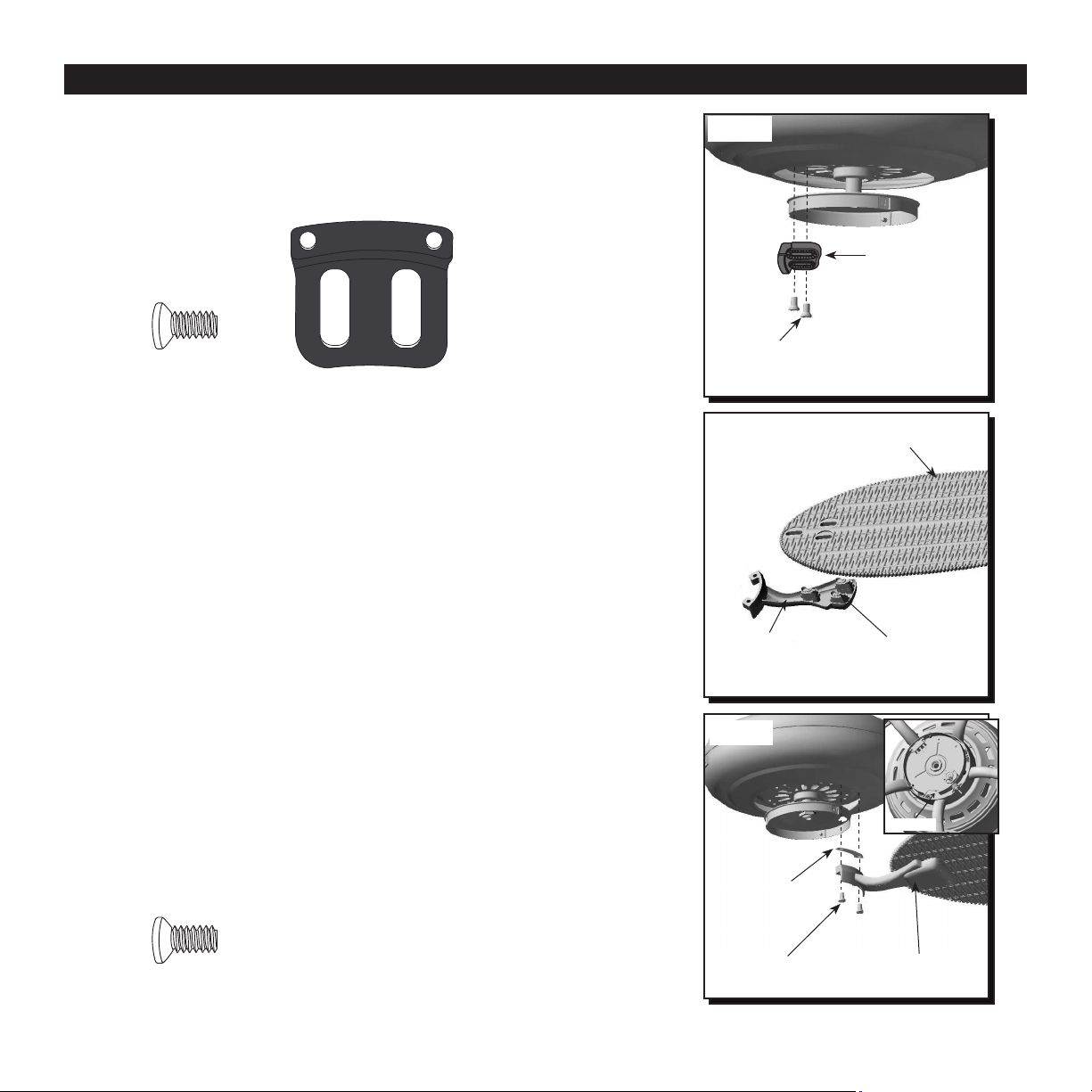
Fig. 20
Fig. 21
Blade
Twist Lock
Connector
Blade Arm
Motor Block
13
BLADE INSTALLATION
19. Remove motor screws from underside of motor and
save for blade arm attachment. If there are plastic
motor blocks installed with the motor screws,
discard the plastic motor blocks but keep the
screws (Fig. 19).
Fig. 19
Fig. 20
Motor Screw
Motor Screw
Motor Screw
Motor Block
20. The blades attach to blade arms using the Fast
Attach
TM
system.
Align each twist lock connector in the direction of
its corresponding hole in the blade. Place the blade
over the twist lock connectors. Rotate each twist
lock connector so that it is perpendicular to the
hole in the blade. Repeat for the remaining blades
(Fig. 20).
Note: A cutout in the upper switch housing allows
easy access to the motor screw holes.
21. Insert two previously removed motor screws
through one blade arm and blade isolator and then
into the motor. Tighten motor screws securely.
Repeat with remaining blade arms, making sure
to completely secure each blade arm before
proceeding with to the next (Fig. 21).
Blade Arm
Motor Screw
Blade Isolator
Cutout
Fig. 21
Loading ...
Loading ...
Loading ...