
www.lg.com
ENGLISH
MONITOR SIGNAGE
MONITOR SIGNAGE MODELS
M2901S
M3801S
Please read this manual carefully before operating
your set and retain it for future reference.
OWNER’S MANUAL

2
Note
• Image sticking is a phenomenon that exhibits temporary retained image or permanent "ghost"
image, due to the prolonged display of static images, which causes chemical or electrical
damage on the display components.
• It is recommended to avoid displaying a fixed static image which is the most common cause of
image sticking.
• When a displayed image is not required, it is recommended to display a Dynamic Image, or an
Active moving Screen Saver.
• Typical Example of Image Sticking
1) For general usage, such as television broadcasting, image sticking can occur on channel
numbers or logos displayed in a fixed position for long periods of time.
2) The displays used at airports and other public transportation stations for displaying customer
information, tend to have the same image or similar contents. Image Sticking occurs when
this type of format or content is used for a long period of time.
3) Letter box format is consistently used with DVD or VCR.
4) When OSD (On Screen Display) such as "Menu" is consistently present on the screen.
• To reduce image sticking or lower the possibility of the phenomena, either use image a sticking
prevention functions inherent in the product such as Orbiter or White Wash, or use special
application contents by the customer.
• Power down the product for a period of time that matches that which caused the issue.
- if image sticking occurred after 10 hours, power down the product for 30 minutes.
- if image sticking occurred after 20 hours, power down the product for 1 hour.
• This phenomenon is common to all manufactures and in consequence the manufactures
warranty does not cover the product bearing this phenomenon.

3
Accessories ................................................................................4
Using the Remote Control .........................................................5
Name of the Remote Control Buttons ..............................................................................5
Inserting batteries into remote control. ...........................................................................5
Name and Function of the Parts ...............................................6
Rear View ..............................................................................................................................6
Connecting to External Devices................................................7
When Connecting to your PC ............................................................................................7
When using the LAN ...........................................................................................................8
Daisy Chain Monitors .........................................................................................................9
VESA FDMI wall Mounting .................................................................................................10
User Menus .................................................................................11
Screen Adjustment options ...............................................................................................11
OSD Menu ............................................................................................................................13
How to adjust the OSD (On Screen Display) screen .....................................................13
How to adjust the screen automatically ..........................................................................13
Adjusting Screen Color ......................................................................................................14
Adjusting the Time function ..............................................................................................16
Adjusting OSD image .........................................................................................................18
Selecting the UTILITY .........................................................................................................19
Adjusting UTILITY ...............................................................................................................20
Troubleshooting .........................................................................21
Specifications ...........................................................................24
Controlling the Multiple Product ...............................................A1
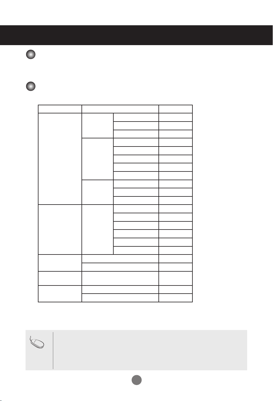
Contents
4
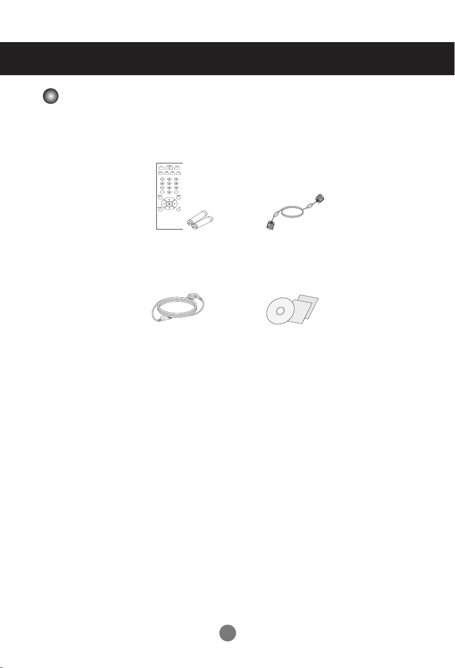
Accessories
Thank you for your purchase. Please check the product as well as the accessories shown below.
❖ Note that the accessories may look different from those shown here.
Remote Control / Batteries
CD-ROM / Cards
D-Sub Signal Cable
Power Cable
Accessories
5
5
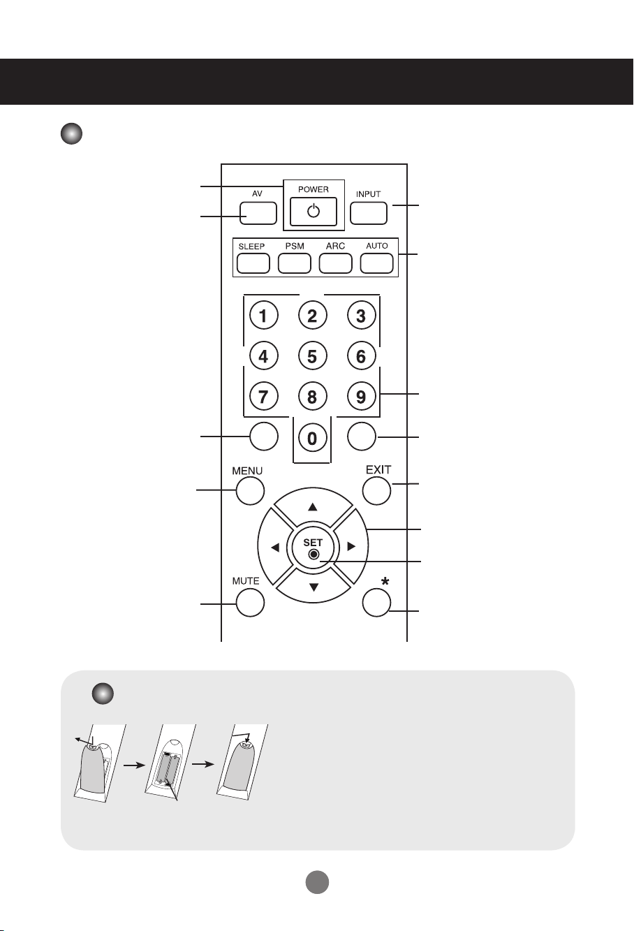
Using the Remote Control
Name of the Remote Control Buttons
• Menu Button
OSD On/Off
Sub OSD Menu out
• ▲ ▼ Buttons
OSD Menu Navigation
• ◄ ► Buttons
Select/ Adjust OSD Menu Item
• SET
Select OSD Menu Item
Show input resolution information
• Sleep Button
Select Sleep Time
• ARC button
Aspect Ratio Correction. Toggles
through aspect ratio options.
• AUTO button
Automatic adjustment function
(Operational for the analog signal only).
• PSM
There is not a function which is
supported.
• Exit Button
Menu Exit
• Key Button
•
Input Button
Select Input Source
(RGB, HDMI)
•
Power Button
Power On/Off
There is not a function
which is supported
There is not a function
which is supported
There is not a function
which is supported
There is not a function
which is supported
There is not a function
which is supported
1. Open the battery compartment cover on the back side and
install the batteries matching correct polarity (+ with +,- with -)
2. Install two 1.5 V AAA batteries. Don’t mix old or used batteries
with new ones.
3. Close cover.
4. To remove the batteries, perform the installation actions in
reverse.
Inserting batteries into remote control.
AAA Type
66
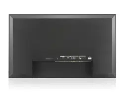
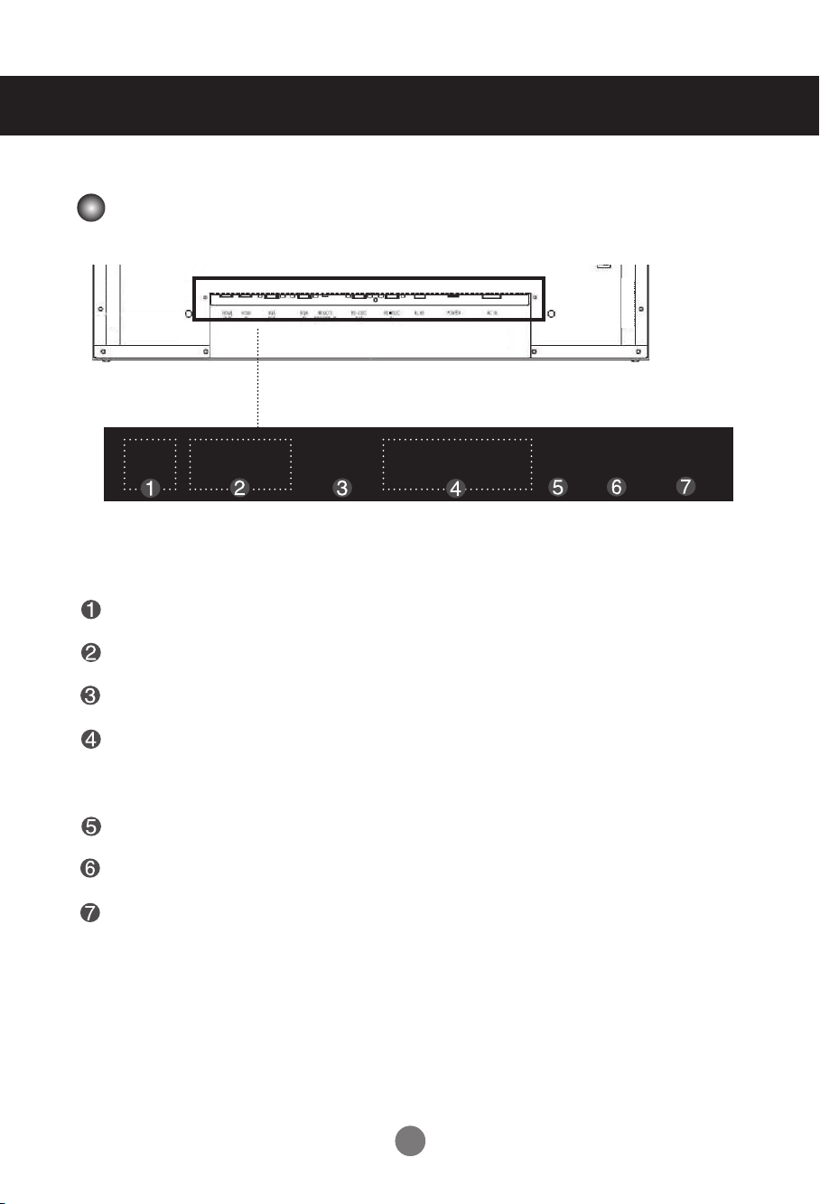
Name and Function of the Parts
* The product image in the user's guide could be different from the actual image.
Rear View
HDMI IN Ports : HDMI signal to HDMI port with HDMI cable.
RGB IN/OUT : RGB signal to RGB port with RGB cable.
EXT. IR : External IR.
RS-232C Serial IN/OUT Port : Connect to the RS-232C port on a PC. For control the
another set, connect a RS-232C Cable from RS-232C
out port to another set's RS-232C input port.
RJ45(eZ-NET) Port : Connect the LAN cable for eZ-NET Manager control.
Power Switch : AC Power On/Off Switch.
AC Power Connector : Connect the power cord.
HDMI
IN
RGB
OUT
RGB
IN
R
S-232CRS-232C
OUT
EXT. IR RS-232C
IN
RJ45 POWER AC IN
77
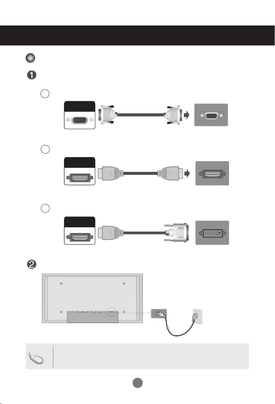
First of all, see if the computer, product and the peripherals are turned off.
Then, connect the signal input cable.
Connect the power cord.
When connecting with the D-Sub signal input cable.
When connecting with the HDMI to DVI signal input cable (not included).
Connecting to External Devices
C
A
PC
PC
Rear side of the product.
Rear side of the product.
(not included)
When Connecting to your PC
RGB
IN
HDMI
IN
HDMI
IN
When connecting with the HDMI signal input cable (not included).
B
PC
Rear side of the product.
(not included)
RGB
IN
HDMI
IN
HDMI
IN
RGB
IN
HDMI
IN
HDMI
IN
Rear side of the product.
• If HDMI signal of input device is abnormal, Something wrong phenomenon or no signal can
happen on screen.
Note
88
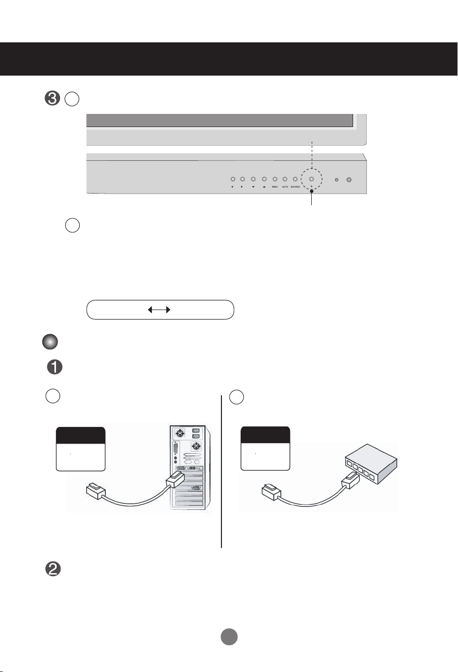
Turn on power by pressing the power button on the product.
Connecting to External Devices
Turn on the PC.
To change input source
Press the SOURCE button on the remote control to select the input signal.
Or, press the SOURCE button on the bottom of the product.
2
1
Power button
HDMI signal D-sub signal
Connect the LAN cable as shown in the below gure .
Connect the LAN cable and install the eZ-Net Manager program on the CD-ROM.
For more information about the program, please refer to eZ-Net Guide in the enclosed
CD-ROM.
When connecting with a PC.
A
When connecting with a Network.
B
PC
Product Product
RJ45 RJ45
RJ45 RJ45
Network
When using the LAN
99
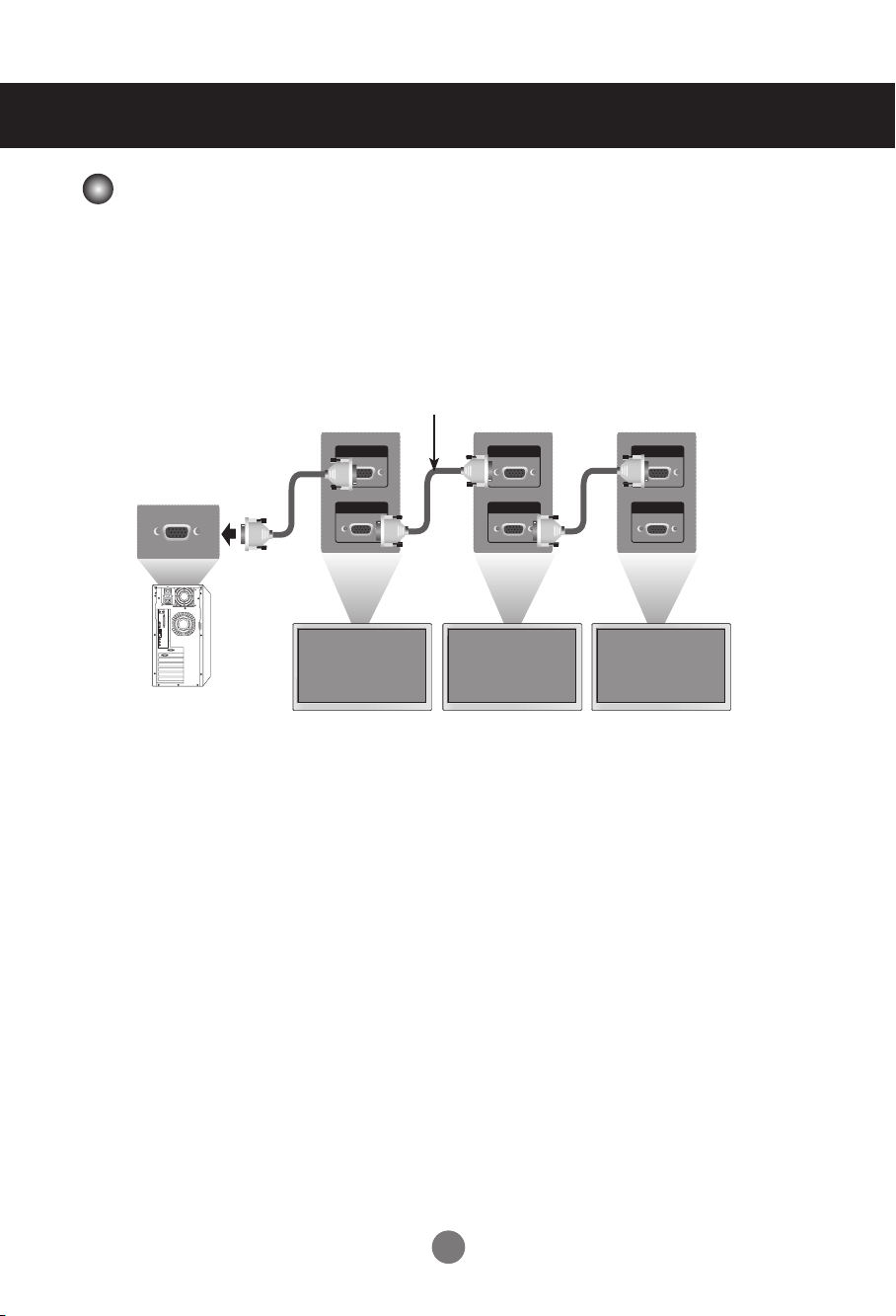
Connecting to External Devices
Use this function when displaying ANALOG RGB inputs of a PC to the other product.
• To use different products connected to each other
Connect one end of the signal input cable(15-pin D-Sub Signal Cable) to the RGB OUT connector of
product 1 and connect the other RGB IN connector of other products.
Case Analog RGB Connect
(Maximum 1.8 m)
RGB IN
RGB OUT
HDMI IN
HDMI OUT
HDMI IN
HDMI OUT
HDMI IN
HDMI OUT
RGB IN
RGB OUT
RGB IN
RGB OUT
Product 1 Product 2
Product 3
PC
Daisy Chain Monitors
10
10
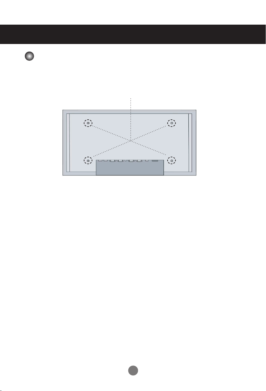
This product supports a VESA FDMI compliant mounting interface. These mounts are
Purchased separately and not available. Refer to the instructions included with the mount
for more info
Connecting to External Devices
VESA FDMI wall Mounting
11
User Menus
Screen Adjustment options
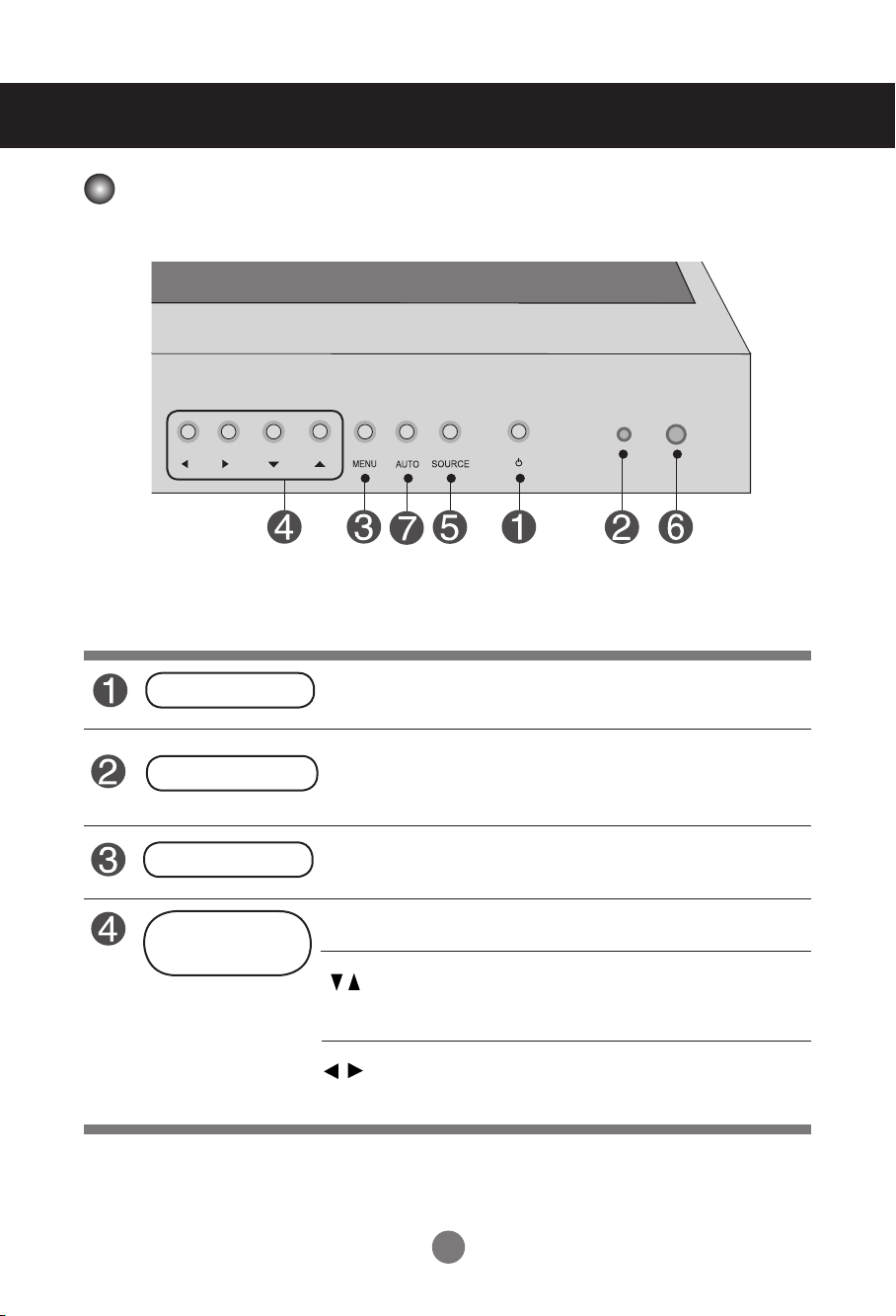
• Press this button to turn on the power. Press this button again to
turn it off.
• This Indicator lights up green when the display operates normally (on
mode). If the display is in sleep (Energy Saving) mode, this indicator color
changes to red.
Power Button
OSD Menu Navigation up and down
▼ : Aspect Ratio Hot key (TOP → Bottom → Stretch)
◄ : Select Menu Item, Decrement Value
► : Select Menu Item, Increment Value
• Use this button to show/hide the OSD (On Screen Display) menu
screen.
MENU Button
• Use
this
button to select an icon or adjust the setting in the OSD screen.
OSD Select /
Adjust Button
Power Indicator
12
User Menus
• This is where the unit receives signals from the remote control.
• Automatic adjustment function.(Operational for the analog signal only)
Screen Adjustment options
• To change input source depending on connected signal.
Press the SOURCE button on the remote control to select the input
signal. Or, press the SOURCE button on the bottom of the product.
SOURCE Button
IR Receiver
Auto Config
HDMI signal RGB Signal
13
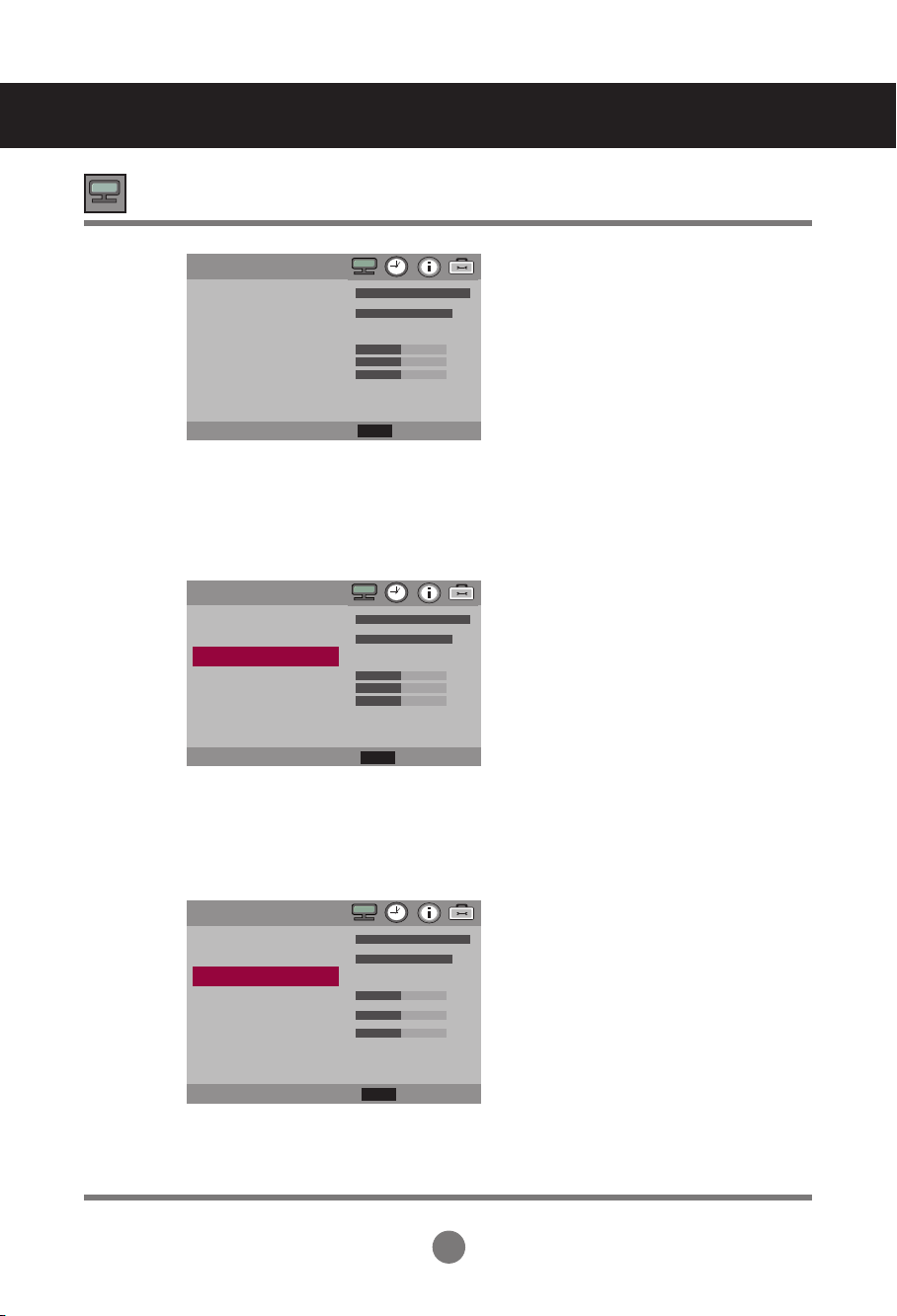
OSD Menu
PICTURE
Adjusts screen brightness, contrast and color that you prefer.
Note
OSD(On Screen Disp lay)
The OSD function enables you to adjust the screen status conveniently since it provides
graphical presentation.
Adjusts Set ID and Set Network.
TIME
Adjusts the OSD menu position.
Adjusts the timer options
UTILITY
OSD
User Menus
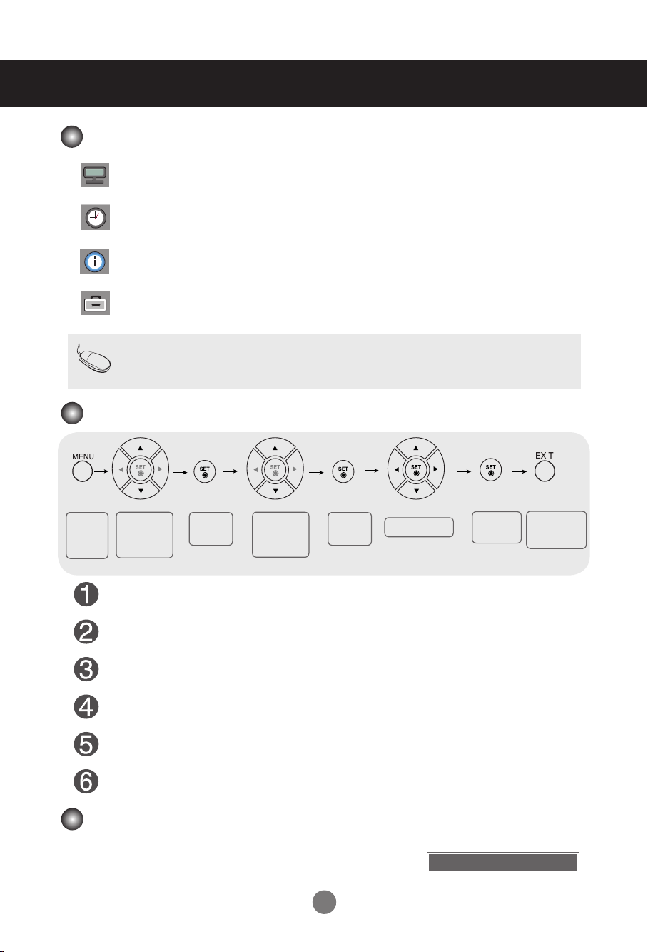
How to adjust the OSD (On Screen Display) screen
How to adjust the screen automatically
Press the AUTO button on a remote Control in the PC analog signal.
Then optimal screen settings will be selected that fit into the current
mode. If adjustment is not satisfactory, you can adjust the screen
manually.
Press the MENU Button, then the main menu of the OSD appears.
To access a control, use the Buttons.
When the icon you want becomes highlighted, press the Button.
Use the Buttons to adjust the item to the desired level.
Accept the changes by pressing the SET Button.
Exit the OSD by pressing the EXIT Button.
•
Use the remote control to adjust the OSD screen.
Pops up
the menu
screen
Move where
you want to
adjust
Move where
you want to
adjust
Select a
menu icon
Select a
menu icon
Adjust the status
Save
adjustment
Exit from the
menu screen.
Auto Cong
14
User Menus
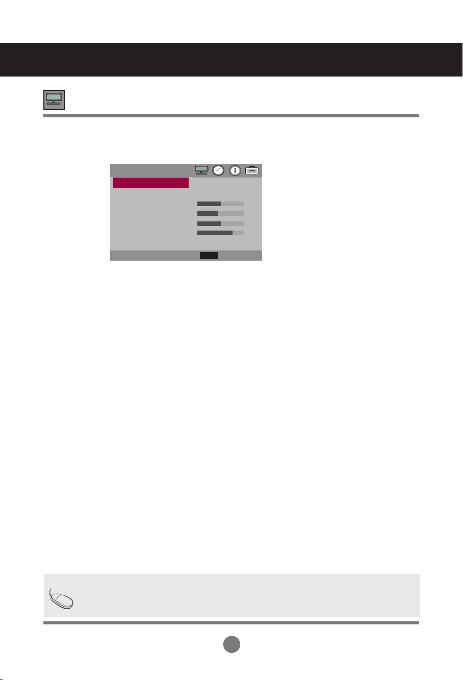
Adjusting Screen Color
To adjust the brightness of the screen.
Adjust the difference between the light and dark levels in the picture.
Color Settings
Brightness
Contrast
Color Temp
Picture
Mode
Red / Green / Blue
Set your own color levels.
• Normal : Slightly bluish white.
• Cool : Slightly purplish white.
• Warm : Slightly reddish white.
• User : Select this option to use the user-defined settings.
Picture
Cool
>
◄► Move
>
Brightness
Contrast
Color Temp
Picture Reset
Screen
Select
Back
MENU
▲
▼
Picture
Brightness
Contrast
Color Temp
Picture Reset
Screen
Normal
>
◄► Move
>
Select
Back
MENU
▲
▼
Picture
User
>
◄► Move
>
Brightness
Contrast
Color Temp
User - R
User - G
User- B
Picture Reset
Screen
Select
Back
MENU
▲
▼
15
Adjusting Screen Color
Return Picture Mode, Color Temp to the default factory Settings.
Adjust the screen video.
Picture Reset
Screen
ARC
XGA Mode
Auto-Config
H-Position
V-Position
Clock
Phase
Screen Reset
To select the image of the screen.(TOP Bottom Stretch)
(M2901S : Case input resolution 1360 x 768)
TOP : It’s composed of 480 line from 1 line of Vertical.
Bottom : It’s composed of 768 line from 481 line of Vertical.
(M3801S : Case input resolution 1920 x 1080)
TOP : It’s composed of 502 line from 1 line of Vertical.
Bottom : It’s composed of 1080 line from 503 line of Vertical.
(RGB PC input only) : For more improved pr better picture quality, select the same mode
corresponding to computer resolution.
(RGB PC input only) : This button is for the automatic adjustment of the screen position, clock
and phase. This function is available for analog signals only.
(RGB PC input only) : Moving the screen position horizontally.
(RGB PC input only) : Moving the screen position vertically.
(RGB PC input only) : To minimize any vertical bars or stripes visible on the screen
background. The horizontal screen size will also change. This function is available for analog
signals only.
(RGB PC input only) : To adjust the focus of the display. This item allows you to remove any
horizontal noise and clear or sharpen the image of characters. This function is available for
analog signals only.
Return Screen Mode to the default factory Settings.
User Menus
• In Stretch/Bottom Mode, Something wrong phenomenon can happen on screen. (ex :
Horizontal stripes noise)
• Stretch Mode is mode for service.
Note
Screen
Stretch
>
>
◄► Move
ARC
Auto - Config
H - Position
V - Position
Clock
Phase
Screen Reset
Select
Back
MENU
▲
▼
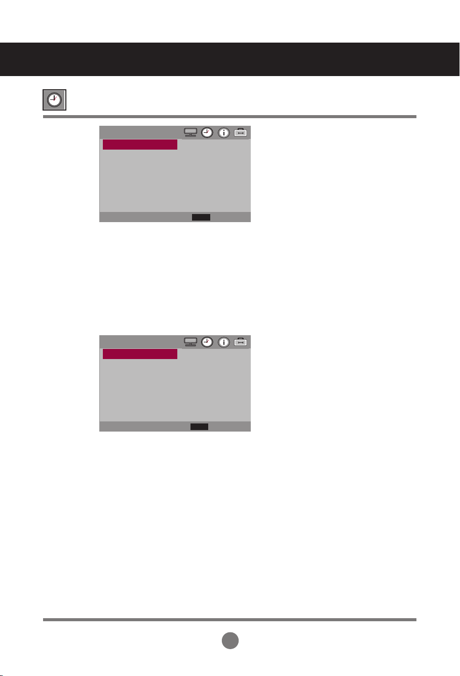
16
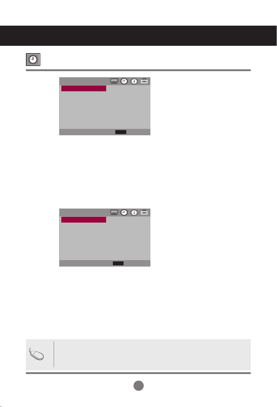
Clock Hour
Clock Minute
Week Day
On/Off Timer
Adjusting the Time function
• In the event of power interruption (disconnection or power failure), the clock must be reset.
• Once the on or off time is set, these functions operate daily at the preset time.
• Off time function overrides On time function if they are set to the same time.
• When On time is operated, input screen is turned on as it was turned off.
Note
If the current time is incorrect, reset the clock manually.
Press the the ◄ ► button to set the hour(00 to 23).
If the current time is incorrect, reset the clock manually.
Press the the
◄ ►
button to set the minutes(00 to 59).
If the current day is incorrect, reset the day manually.
Press the the
◄ ►
button to set the day(MON, TUE, WED, THU, FRI, SAT, SUN).
The off time automatically switches the set to standby at the pre-set time.
• Schedule : Use the user-defined settings.
(Everyday, MON, TUE, WED, THU, FRI, SAT, SUN).
• On Hour : Use the user-defined settings.(00 to 23)
• On Minute : Use the user-defined settings.(00 to 59)
• On Timer Enable : Use the user-defined settings.(On, Off)
• Off Hour : Use the user-defined settings.(00 to 23)
• Off Minute : Use the user-defined settings .(00 to 59)
• Off Timer Enable : Use the user-defined settings.(On, Off)
User Menus
Time
00
00
FRI
>
Off
Off
>
◄► Move
Clock Hour
Clock Minute
Week Day
On/Off Timer
Sleep Time
Auto Sleep
Power Saving
ON / OFF TIMER
Everyday
00
00
Off
00
00
Off
◄► Move
Schedule
On Hour
On Minute
On Timer Enable
Off Hour
Off Minute
Off Timer Enable
Select
Back
MENU
▲
▼
Select
Back
MENU
▲
▼
17
Sleep Time
Auto Sleep
Power Saving
The power is automatically turned off when the time set by a user is passed.
Press the the ◄ ► button to set the time(Off, 10, 20, 30, 60, 90, 120, 180, 240).
If Auto Sleep is active and there is no input signal, the set switches to off mode automatically
after about 10 sec.
ON : Automatically turn the product On/Off at preset times.
OFF : Disable the On/Off Time function.
This screen brightness adjusting menu helps you save energy.
• Level : Total 4 screen brightness levels are provided.
- Off : 100% light
- Level 1 : 80% light
- Level 2 : 60% light
- Level 3 : 40% light
• On Hour : Use the user-defined settings.(00 to 23)
• On Minute : Use the user-defined settings.(00 to 59)
• Off Hour : Use the user-defined settings.(00 to 23)
• Off Minute : Use the user-defined settings.(00 to 59)
* On/Off Hour and Minute: Enables to automatically turn on/off the power saving option at a
scheduled time.
* The power saving option becomes in effect only during the scheduled time frame.
Adjusting the Time function
User Menus
Time
00
00
FRI
>
Off
Off
>
◄► Move
Clock Hour
Clock Minute
Week Day
On/Off Timer
Sleep Time
Auto Sleep
Power Saving
POWER SAVING
Off
00
00
00
00
◄► Move
Level
On Hour
On Minute
Off Hour
Off Minute
Select
Back
MENU
▲
▼
Select
Back
MENU
▲
▼
18
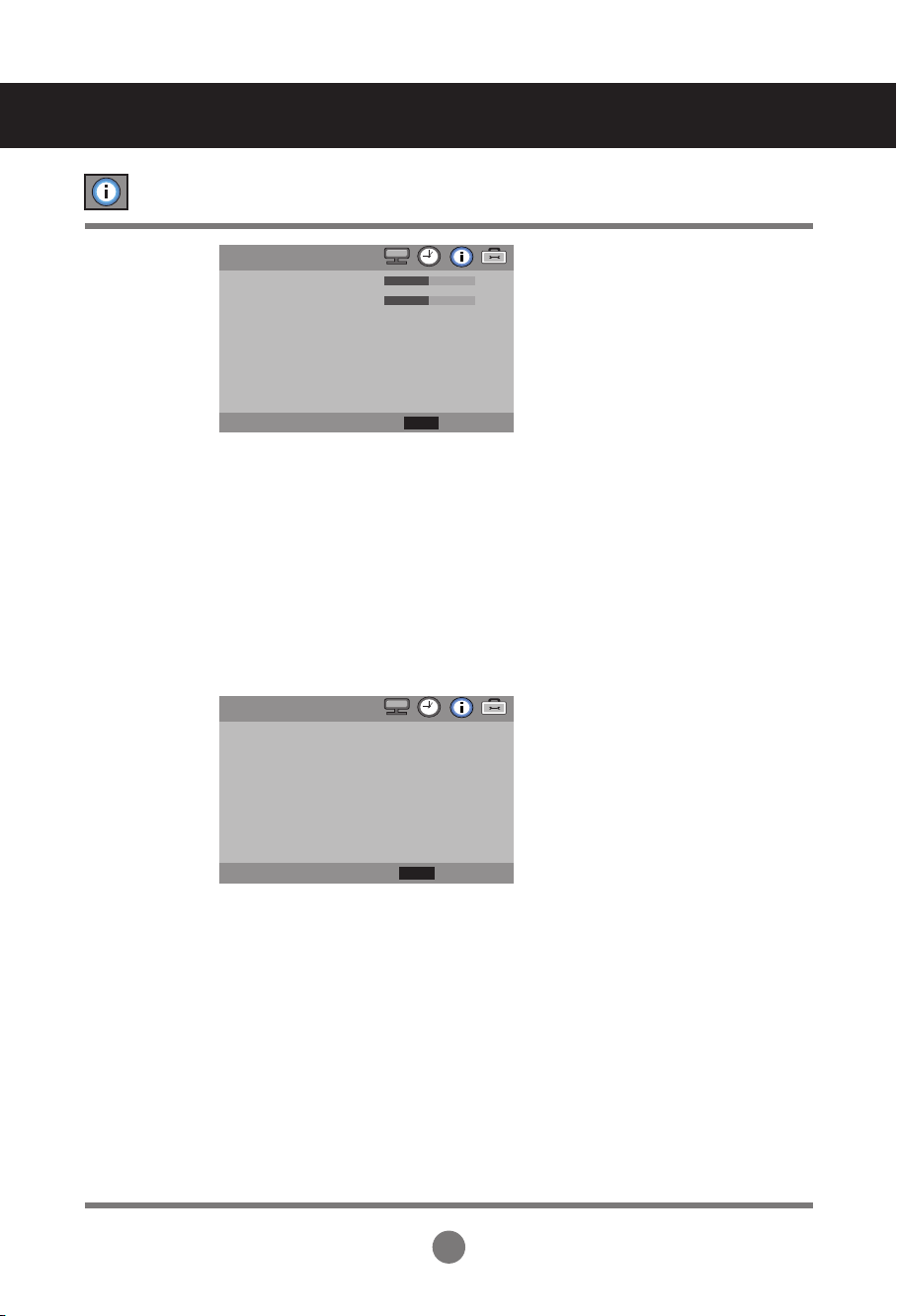
Adjusting OSD image
H-Position
V-Position
Display Time
Information
Moving the OSD screen position horizontally.
Moving the OSD screen position vertically.
To set the period of time that the OSD is displayed on the screen.
(Available times : Off, 15, 30, 45, 60second.)
This menu shows the input source and software version of the product.
User Menus
OSD
Off
>
◄► Move
H-Position
V-Position
Display Time
Information
Select
Back
MENU
▲
▼
Information
◄► Move
<Information>
Source : RGB
Resol : 1280 x 1024(P)
H Freq : 64 KHz
V Freq : 60 Hz
Version : LG 0.20
Select
Back
MENU
▲
▼
19
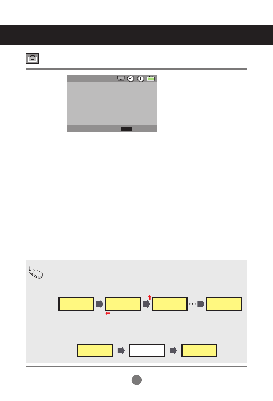
Set ID
Power Indicator
DPM Select
Orbiter
White Wash
Network Setup
You can assign a unique Set ID NO (name assignment) to each product when several
products are connected for display. Specify the number (1 to 99) using the ◄ ► button and
exit. Use the assigned Set ID to individually control each product using the Product Control
Program.
Use the function to the set power indicator on the front side of the product to On or Off.
A user can choose to turn the power saving mode on/off.
A user can choose to reduce screen image sticking.
It will change the position of the image within a defined interval.
A user can choose to reduce screen image sticking.
White Wash fills the screen with solid white.
Setup network information.
Selecting the UTILITY
User Menus
UTILITY
◄► Move
Set ID
Power Indicator
DPM Select
Orbiter
White Wash
Network Setup
Factory Reset
1
On
Off
Off
Off
>
>
Select
Back
MENU
▲
▼
Note
1) Orbiter
Orbiter function will change the position of the image within a defined interval.
The image on the screen will be moved slightly in sequence such as below.
It will move 2 pixel every 30 second in a counterclockwise direction after moving 2 pixel every 30
second in a clockwise direction. And then it will be repeated in equal sequence every 30 minutes.
2) White Wash
White Wash fills the screen with solid white. It will recover to original image after 5 minutes.
This helps removes permanent images burned into the screen.
A permanent image may be impossible to clear entirely with white wash.
Stretched Monitor Stretched MonitorStretched Monitor
Stretched Monitor
Stretched Monitor Stretched Monitor
20
Adjusting UTILITY
User Menus
*If Network Select is set to Serial, DHCP and Manual are disabled.
Wait for IP Setup
IP Setup Completed
Factory Reset Select this option to return to the default factory settings.
MANUAL SETTING
◄► Move
IP Address
Subnet Mask
Default Gateway
Primary DNS
Secondary DNS
Execute
192. 168. 000 .010
255. 255. 255. 000
192. 168. 000. 001
192. 168. 000. 001
192. 168. 000. 001
>
Select
Back
MENU
▲
▼
• Network Select : Sets up network connections.
- RS-232 : Enable communication via Serial.
- LAN : Enable communication via Ethernet.
• DHCP : Allocates and sets up IP automatically.
• Manual : Sets up IP address, Gateway, Subnet Mask, Primary DNS and Secondary DNS.
The setup process is complete when you select Execute, and "IP Setup
Completed" is displayed at the bottom of the screen. While "Wait for IP Setup" is
displayed, you cannot use the local keys and remote control. "Wait for IP Setup" is
displayed for up to 40seconds.
NETWORK SETUP
◄► Move
LAN
>
>
Network Select
DHCP
Manual
Select
Back
MENU
▲
▼
21
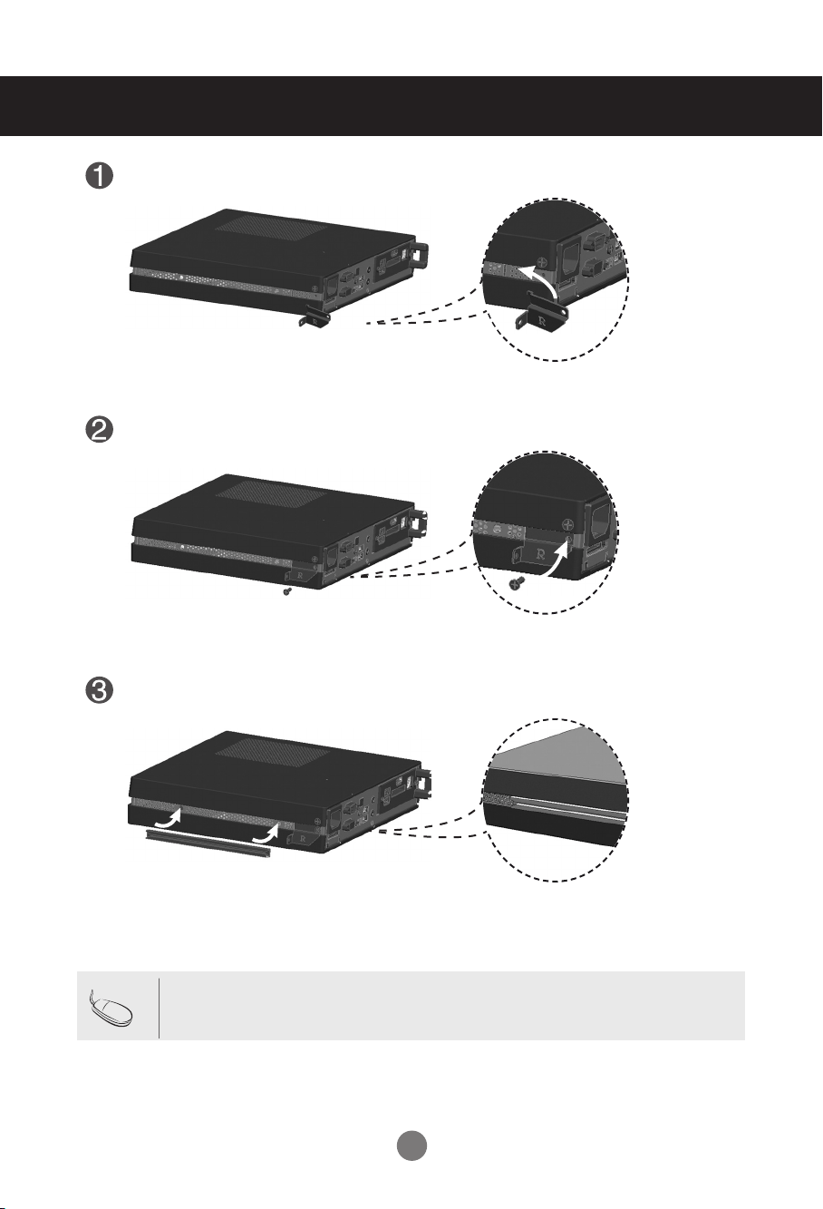
Place the handle into the slots on the side of the product.
Use screws to secure the handle.
Place the rail in the slots on the side of the product.
•
Be careful of sharp edges on the rail and the handle.
Note
Connecting M3801S and NC1100
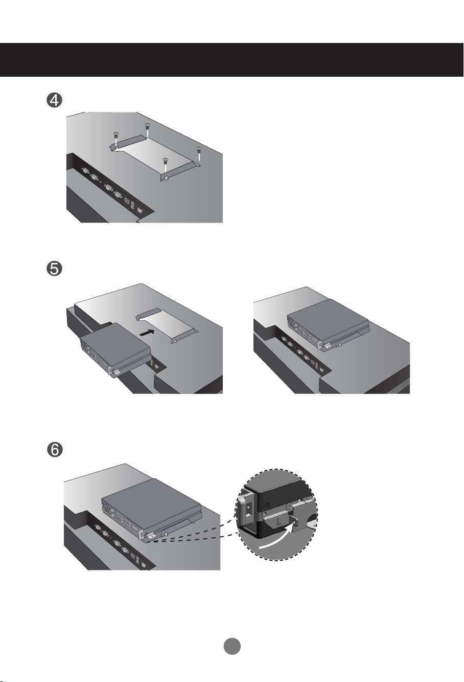
22
As shown below, use screws to secure the Box Guide in the four slots at the back of the monitor.
Attach the Box Guide to the rail slots, and press it upward.
Use screws to secure the player and the Box Guide as shown below.
Connecting M3801S and NC1100
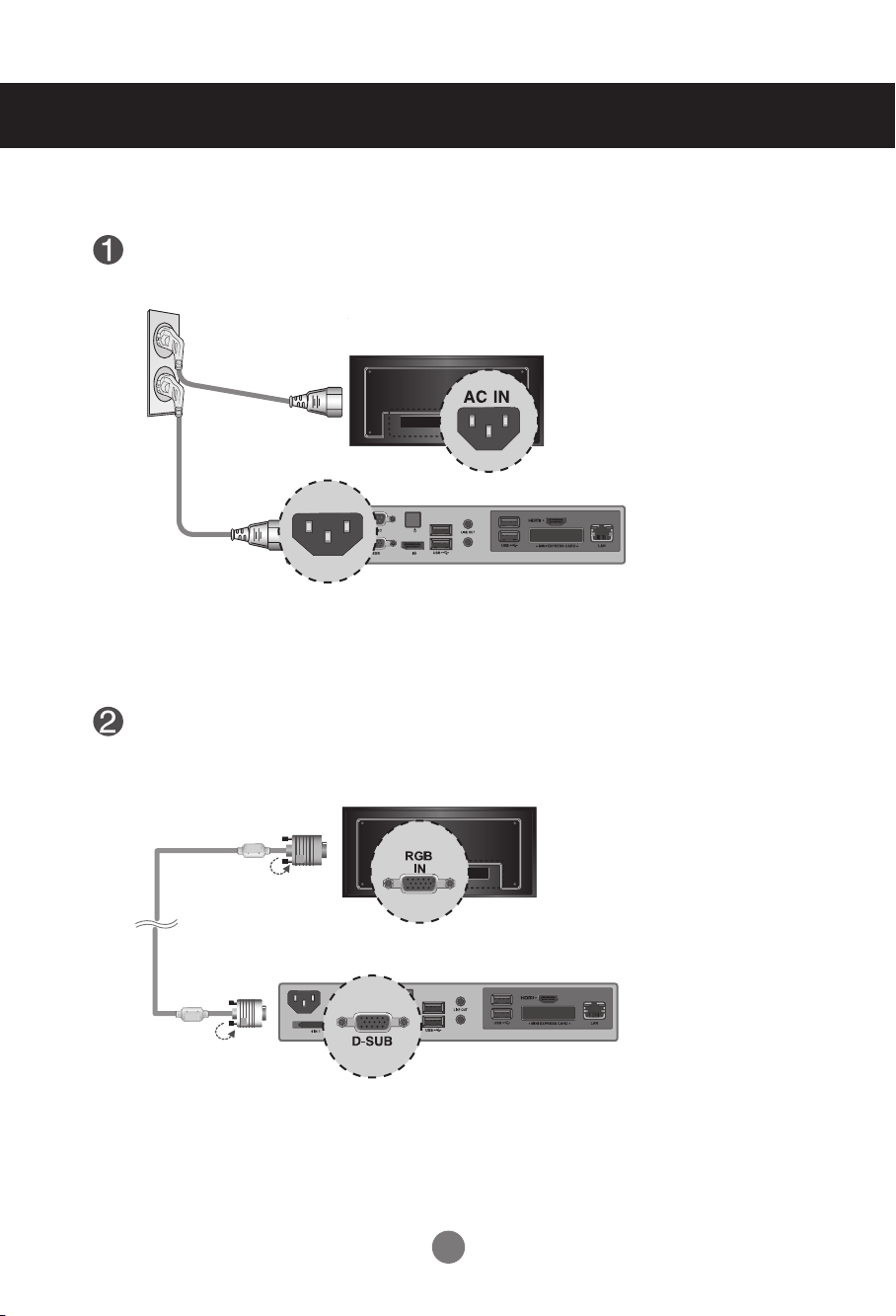
23
Connect the appropriate power cables to a monitor and NC1100 respectively.
Connect the D-sub port of NC1100 and RGB-IN port of the monitor with a D-sub cable.
MIC IN
PW
MIC IN
PW
MIC IN
PW
MIC IN
PW
MIC IN
PW
HDMI
IN
RGB
OUT
RGB
IN
RS-232C
RS-232C
OUT
EXT. IR
RS-232C
IN
RJ45 POWER AC IN
HDMI
IN
RGB
OUT
RGB
IN
R
S
-2
3
2
C
RS-232C
OUT
EXT. IR
RS-232C
IN
RJ45 POWER AC IN
HDMI
IN
RGB
OUT
RGB
IN
R
S
-2
3
2
C
RS-232C
OUT
EXT. IR
RS-232C
IN
RJ45 POWER AC IN
HDMI
IN
RGB
OUT
RGB
IN
R
S
-2
3
2
C
RS-232C
OUT
EXT. IR RS-232C
IN
RJ45 POWER AC IN
HDMI
IN
RGB
OUT
RGB
IN
RS-232
C
RS-232C
OUT
EXT. IR RS-232C
IN
RJ45 POWER AC IN
MIC IN
PW
MIC IN
PW
MIC IN
PW
MIC IN
PW
MIC IN
PW
HDMI
IN
RGB
OUT
RGB
IN
R
S
-2
3
2
C
RS-232C
OUT
EXT. IR
RS-232C
IN
RJ45 POWER AC IN
HDMI
IN
RGB
OUT
RGB
IN
R
S
-2
3
2
C
RS-232C
OUT
EXT. IR
RS-232C
IN
RJ45 POWER AC IN
HDMI
IN
RGB
OUT
RGB
IN
R
S
-2
3
2
C
RS-232C
OUT
EXT. IR
RS-232C
IN
RJ45 POWER AC IN
HDMI
IN
RGB
OUT
RGB
IN
R
S
-2
3
2
C
RS-232C
OUT
EXT. IR RS-232C
IN
RJ45 POWER AC IN
HDMI
IN
RGB
OUT
RGB
IN
RS-232
C
RS-232C
OUT
EXT. IR RS-232C
IN
RJ45 POWER AC IN
MIC IN
PW
MIC IN
PW
MIC IN
PW
MIC IN
PW
MIC IN
PW
HDMI
IN
RGB
OUT
RGB
IN
R
S
-2
3
2
C
RS-232C
OUT
EXT. IR
RS-232C
IN
RJ45 POWER AC IN
HDMI
IN
RGB
OUT
RGB
IN
RS-232C
RS-232C
OUT
EXT. IR
RS-232C
IN
RJ45 POWER AC IN
HDMI
IN
RGB
OUT
RGB
IN
R
S
-2
3
2
C
RS-232C
OUT
EXT. IR
RS-232C
IN
RJ45 POWER AC IN
HDMI
IN
RGB
OUT
RGB
IN
R
S
-2
3
2
C
RS-232C
OUT
EXT. IR RS-232C
IN
RJ45 POWER AC IN
HDMI
IN
RGB
OUT
RGB
IN
RS-232
C
RS-232C
OUT
EXT. IR RS-232C
IN
RJ45 POWER AC IN
MIC IN
PW
MIC IN
PW
MIC IN
PW
MIC IN
PW
MIC IN
PW
HDMI
IN
RGB
OUT
RGB
IN
R
S
-2
3
2
C
RS-232C
OUT
EXT. IR
RS-232C
IN
RJ45 POWER AC IN
HDMI
IN
RGB
OUT
RGB
IN
R
S
-2
3
2
C
RS-232C
OUT
EXT. IR
RS-232C
IN
RJ45 POWER AC IN
HDMI
IN
RGB
OUT
RGB
IN
R
S
-2
3
2
C
RS-232C
OUT
EXT. IR
RS-232C
IN
RJ45 POWER AC IN
HDMI
IN
RGB
OUT
RGB
IN
R
S
-2
3
2
C
RS-232C
OUT
EXT. IR RS-232C
IN
RJ45 POWER AC IN
HDMI
IN
RGB
OUT
RGB
IN
RS-232
C
RS-232C
OUT
EXT. IR RS-232C
IN
RJ45 POWER AC IN
24
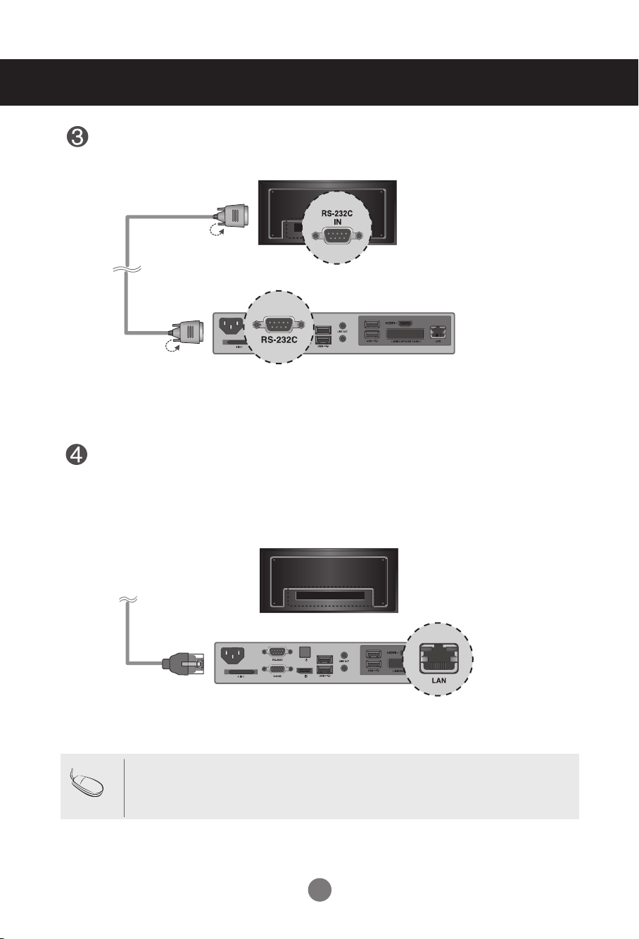
Connect a LAN cable to the NC1100.
MIC IN
PW
MIC IN
PW
MIC IN
PW
MIC IN
PW
MIC IN
PW
HDMI
IN
RGB
OUT
RGB
IN
R
S
-2
3
2
C
RS-232C
OUT
EXT. IR
RS-232C
IN
RJ45 POWER AC IN
HDMI
IN
RGB
OUT
RGB
IN
R
S
-2
3
2
C
RS-232C
OUT
EXT. IR
RS-232C
IN
RJ45 POWER AC IN
HDMI
IN
RGB
OUT
RGB
IN
R
S
-2
3
2
C
RS-232C
OUT
EXT. IR
RS-232C
IN
RJ45 POWER AC IN
HDMI
IN
RGB
OUT
RGB
IN
R
S
-2
3
2
C
RS-232C
OUT
EXT. IR RS-232C
IN
RJ45 POWER AC IN
HDMI
IN
RGB
OUT
RGB
IN
RS-232
C
RS-232C
OUT
EXT. IR RS-232C
IN
RJ45 POWER AC IN
MIC IN
PW
MIC IN
PW
MIC IN
PW
MIC IN
PW
MIC IN
PW
HDMI
IN
RGB
OUT
RGB
IN
R
S
-2
3
2
C
RS-232C
OUT
EXT. IR
RS-232C
IN
RJ45 POWER AC IN
HDMI
IN
RGB
OUT
RGB
IN
R
S
-2
3
2
C
RS-232C
OUT
EXT. IR
RS-232C
IN
RJ45 POWER AC IN
HDMI
IN
RGB
OUT
RGB
IN
R
S
-2
3
2
C
RS-232C
OUT
EXT. IR
RS-232C
IN
RJ45 POWER AC IN
HDMI
IN
RGB
OUT
RGB
IN
R
S
-2
3
2
C
RS-232C
OUT
EXT. IR RS-232C
IN
RJ45 POWER AC IN
HDMI
IN
RGB
OUT
RGB
IN
RS-232
C
RS-232C
OUT
EXT. IR RS-232C
IN
RJ45 POWER AC IN
Connect NC1100 (OUT) to the monitor (IN) with an RS-232C cable.
MIC IN
PW
MIC IN
PW
MIC IN
PW
MIC IN
PW
MIC IN
PW
HDMI
IN
RGB
OUT
RGB
IN
R
S
-2
3
2
C
RS-232C
OUT
EXT. IR
RS-232C
IN
RJ45 POWER AC IN
HDMI
IN
RGB
OUT
RGB
IN
R
S
-2
3
2
C
RS-232C
OUT
EXT. IR
RS-232C
IN
RJ45 POWER AC IN
HDMI
IN
RGB
OUT
RGB
IN
RS-232C
RS-232C
OUT
EXT. IR
RS-232C
IN
RJ45 POWER AC IN
HDMI
IN
RGB
OUT
RGB
IN
R
S
-2
3
2
C
RS-232C
OUT
EXT. IR RS-232C
IN
RJ45 POWER AC IN
HDMI
IN
RGB
OUT
RGB
IN
RS-232
C
RS-232C
OUT
EXT. IR RS-232C
IN
RJ45 POWER AC IN
MIC IN
PW
MIC IN
PW
MIC IN
PW
MIC IN
PW
MIC IN
PW
HDMI
IN
RGB
OUT
RGB
IN
R
S
-2
3
2
C
RS-232C
OUT
EXT. IR
RS-232C
IN
RJ45 POWER AC IN
HDMI
IN
RGB
OUT
RGB
IN
R
S
-2
3
2
C
RS-232C
OUT
EXT. IR
RS-232C
IN
RJ45 POWER AC IN
HDMI
IN
RGB
OUT
RGB
IN
R
S
-2
3
2
C
RS-232C
OUT
EXT. IR
RS-232C
IN
RJ45 POWER AC IN
HDMI
IN
RGB
OUT
RGB
IN
R
S
-2
3
2
C
RS-232C
OUT
EXT. IR RS-232C
IN
RJ45 POWER AC IN
HDMI
IN
RGB
OUT
RGB
IN
RS-232
C
RS-232C
OUT
EXT. IR RS-232C
IN
RJ45 POWER AC IN
• For information on connecting the HDMI in Windows, see the Owner's Manual.
• HDMI cable is not provided with the product. Please purchase any optional items as
needed.
Note
25
The properties that can be controlled in the General Control area are as follows:
● Display power (On/Off)
In the Advanced Control area, you can control various properties of the displays in the group.
Item Details
SUPPORT
Display Information Device player name
o
device name
o
serial number
o
Status power
o
input
o
signal
o
volume
x
mute
x
Self diagnosis fan
x
panel
o
temperature
x
Video Input type
AV x
Component
x
RGB o
HDMI/DVI(DTV) x
HDMI/DVI(PC) o
SuperSign x
Audio Volume
x
Mute
x
Time Sets the time sync of SuperSign
Manager
o
General Remote control/local key lock
o
Advanced controls
o
General Control
Advanced Control
• You can also select and control a display in List view mode.
• The following messages can be received:
* OK: Normal
* NG: If the media player is not connected to SuperSign Manager or an error occurs in the
monitor
* N/A: If the menu is not available on the monitor
Note

26
Troubleshooting
• See if the power cord is properly connected to the outlet.
• See if the power switch is turned on.
• May need service.
• Adjust brightness and contrast again.
• Backlight may need repair.
• If the product is in power saving mode, move the mouse
or press any key.
• Turn both devices off and then back on.
• The signal from the PC (video card) is out of the vertical
or horizontal frequency range of the product. Adjust the
frequency range by referring to the Specifications in this
manual.
* Maximum resolution
M2901S RGB : 1360 x 768 @ 60 Hz
HDMI/DVI : 1360 x 768 @ 60 Hz
M3801S RGB : 1920 x 1080 @ 60 Hz
HDMI/DVI : 1920 x 1080 @ 60 Hz
• The signal cable between PC and product is not
connected. Check the signal cable.
• Press the 'SOURCE' menu in the remote Control to
check the input signal.
●
Is the product power cord connected?
●
Is the power indicator light on?
●
Power is on, power indicator is green but the
screen appears extremely dark.
●
The power indicator Red?
●
Does the 'Out of range' message appear?
●
Does the 'no signal' message appear?
No image is displayed
• Install the product driver, which is provided with the
product, or download it from the web site. (http://www.
lg.com)
● Did you install the driver?
'Unknown Product' message appears when the product is connected.

27
Troubleshooting
●
Is the screen position wrong?
●
Do thin lines appear on the background
screen?
●
Horizontal noise appears or the characters
look blurred.
●
The screen is displayed abnormally.
The screen image looks abnormal.
• D-Sub analog signal - Press the "AUTO" button in the
remote control to automatically select the optimal screen
status that fits into the current mode. If adjustment is not
satisfactory, use the Position OSD menu.
• See if the video card resolution and frequency are
supported by the product. If the frequency is out of
range, set to the recommended resolution in the Control
Panel - Display - Setting menu.
• D-Sub analog signal - Press the "AUTO" button in the
remote control to automatically select an optimal screen
status that fits into the current mode. If adjustment is not
satisfactory, use the Clock OSD menu.
• D-Sub analog signal - Press the "AUTO" button in the
remote control to automatically select an optimal screen
status that fits into the current mode. If adjustment is not
satisfactory, use the Phase OSD menu.
• The proper input signal is not connected to the signal
port. Connect the signal cable that matches with the
source input signal.
• If you use a fixed image for a long time, the pixels may
be damaged quickly. Use the screen-saver function.
●
After-image appears when the product is
turned off.
After-image appears on the product.
28
Troubleshooting
• Set the number of colors to more than 24 bits (true color)
Select Control Panel - Display - Settings - Color
Table menu in Windows.
• Check the connection status of the signal cable. Or,
re-insert the PC video card.
• Several pixels (red, green, white or black color) may
appear on the screen, which can be attributable to the
unique characteristics of the LCD panel. It is not a
malfunction of the LCD.
●
Screen has poor color resolution (16 colors).
●
Screen color is unstable or mono-colored.
●
Do black spots appear on the screen?
Screen color is abnormal.
• Is the sleep timer set?
• Check the power control settings.
Power interrupted.
• "CAUTION! FAN STOP!"
If the power is turned off after this message appears,
it means that the fan is out of order.
In this case, contact your local service center.
● The power suddenly turned off.
After-image appears on the product.

29
Specications
NOTE
Information in this document is subject to change without notice.
The product specifications can change without prior notice for product improvement.
M2901S
LCD Panel 73.91 cm (29.1 inch) TFT (Thin Film Transistor) LCD (Liquid Crystal Display) Panel
Visible diagonal size: 73.91 cm
0.1703 mm x RGB x 0.5108 mm (Pixel Pitch)
Power Rated Voltage
Power Consumption
AC 100-240 V~ 50 / 60 Hz 1.3 A
On Mode : 90 W (Max.)
DPM Mode : ≤ 1.0 W (Max.)
SW-OFF Mode : ≤ 0.5 W
Off Mode : ≤ 0.3 W
Dimensions & Weight
Width x Height x Depth
76.34 cm (30.05 inch) x 30.58 cm (12.03 inch) x 8.55 cm (3.36 inch)
Net
11.0 kg (24.25 lb)
Video Signal
Max. Resolution RGB : 1360 x 768 @ 60 Hz
HDMI/DVI : 1366 x 768 @ 60 Hz - It may not be supported
depending on the OS or video card type.
Recommended
Resolution
RGB : 1366 x 768 @ 60 Hz
HDMI/DVI : 1366 x 768 @ 60 Hz - It may not be supported
depending on the OS or video card type.
Horizontal Frequency RGB : 28 kHz to 70 kHz
HDMI/DVI : 28 kHz to 70 kHz
Vertical Frequency RGB : 57 Hz to 63 Hz
HDMI/DVI : 57 Hz to 63 Hz
Synchronization Type Separate/Digital
Input Connector 15-pin D-Sub type, HDMI (digital), RS-232C, LAN
Environmental
Conditions
Operational Condition Temperature: 5 °C to 35 °C , Humidity: 10 % to 80 %
Storage Condition Temperature: -20 °C to 60 °C , Humidity: 5 % to 90 %
W
H
D

30
M3801S
LCD Panel 96.26 cm (37.9 inch) TFT (Thin Film Transistor) LCD (Liquid Crystal Display) Panel
Visible diagonal size: 96.26 cm
0.4845 mm x RGB x 0.4845 mm (Pixel Pitch)
Power Rated Voltage
Power Consumption
AC 100-240 V~ 50 / 60 Hz 1.5 A
On Mode : 110 W (Max.)
DPM Mode : ≤ 1.0 W (Max.)
SW-OFF Mode : ≤ 0.5 W
Off Mode : ≤ 0.3 W
Dimensions & Weight
Width x Height x Depth
98.64 cm (38.83 inch) x 29.94 cm (11.78 inch) x 9.0 cm (3.54 inch)
Net
13.8 kg (30.42 lb)
Video Signal
Max. Resolution RGB : 1920 x 1080 @ 60 Hz
HDMI/DVI : 1920 x 1080 @ 60 Hz - It may not be supported
depending on the OS or video card type.
Recommended
Resolution
RGB : 1920 x 1080 @ 60 Hz
HDMI/DVI : 1920 x 1080 @ 60 Hz - It may not be supported
depending on the OS or video card type.
Horizontal Frequency RGB : 28 kHz to 70 kHz
HDMI/DVI : 28 kHz to 70 kHz
Vertical Frequency RGB : 57 Hz to 63 Hz
HDMI/DVI : 57 Hz to 63 Hz
Synchronization Type Separate/Digital
Input Connector 15-pin D-Sub type, HDMI (digital), RS-232C, LAN
Environmental
Conditions
Operational Condition Temperature: 5 °C to 35 °C , Humidity: 10 % to 80 %
Storage Condition Temperature: -20 °C to 60 °C , Humidity: 5 % to 90 %
W
H
D
Specications
The product specifications can change without prior notice for product improvement.
NOTE
Information in this document is subject to change without notice.
31
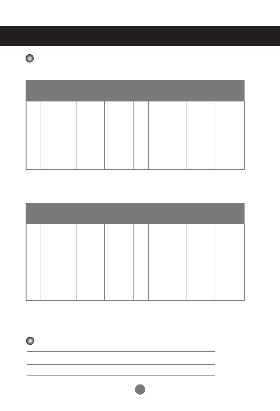
* 5, 6, 12 to 14 Select Resolution In SCREEN XGA Mode Menu
* 6, 7, 12 to 14 Select Resolution In SCREEN XGA Mode Menu
Specications
PC Mode - Preset Mode
M2901S
M3801S
Power Indicator
Mode On Mode DPM Mode SW-OFF Mode Off Mode
Product Green Red Red -
Preset mode
Horizontal
Frequency
(kHz)
Vertical
Frequency
(Hz)
Preset mode
Horizontal
Frequency
(kHz)
Vertical
Frequency
(Hz)
1 640 x 480 31.469 59.94 9 1280 x 720 45.0 60.0
2 720 x 400 31.468 70.08 10 1280 x 960 60.0 60.0
3 800 x 600 37.354 59.861 11 1360 X 480 29.934 59.988
4 800 x 600 37.879 60.317 12 1360 x 768 47.72 59.799
5 1024 x 768 47.816 59.92 13 1360 x 768 47.712 60.015
6 1024 x 768 48.363 60.004 14 1366 x 768 47.13 59.66
7 1152 x 864 54.348 60.053 15 1280 x 1024 63.668 59.895
8 1280 x 720 44.772 59.856 16 1280 x 1024 63.981 60.02
Preset mode
Horizontal
Frequency
(kHz)
Vertical
Frequency
(Hz)
Preset mode
Horizontal
Frequency
(kHz)
Vertical
Frequency
(Hz)
1 640 x 480 31.469 59.94 10 1280 x 720 44.772 59.856
2 720 x 400 31.468 70.08 11 1280 x 960 60.0 60.0
3 720 x 400 31.5 70.156 12 1360 x 768 47.72 59.799
4 800 x 600 37.354 59.861 13 1360 x 768 47.712 60.015
5 800 x 600 37.879 60.317 14 1366 x 768 47.13 59.66
6 1024 x 768 47.816 59.92 15 1280 x 1024 63.668 59.895
7 1024 x 768 48.363 60.004 16 1280 x 1024 63.981 60.02
8 1920 x 502 31.25 59.981 17 1920 x 1080 66.587 59.934
9 1152 x 864 54.348 60.053 18 1920 x 1080 67.5 60.0
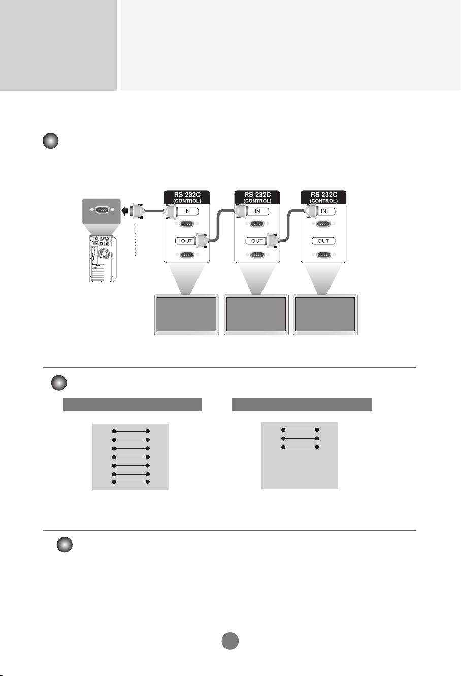
Controlling the Multiple Product
RS-232C
A1
A1
Connecting the cable
- Connect the RS-232C cable as shown in the picture.
■ The RS-232C protocol is used for communication between the PC and product. You can turn
the product on/off, select an input source or adjust the OSD menu from your PC.
■ Use this method to connect several products to a single PC. You can control several products at a
time by connecting them to a single PC.
RS-232C Cable
(not included)
monitor 1
PC
monitor 2
monitor 3
7-Wire Configurations (Standard RS-232C cable)
TXD
RXD
GND
DSR
DTR
CTS
RTS
TXD
RXD
GND
DSR
DTR
CTS
RTS
PC Monitor
2
3
5
4
6
7
8
2
3
5
4
6
7
8
D-Sub 9 D-Sub 9
(Female) (Male)
3-Wire Configurations (Not Standard RS-232C cable)
TXD
RXD
GND
DSR
DTR
CTS
RTS
TXD
RXD
GND
DSR
DTR
CTS
RTS
PC Monitor
2
3
5
4
6
7
8
2
3
5
4
6
7
8
D-Sub 9 D-Sub 9
(Female) (Female)
► Baud Rate : 9600 buad Rate (UART)
► Data Length : 8 bit
► Parity Bit : None
► Stop Bit : 1bit
► Flow Control : None
► Communication Code : ASCII code
► Use a crossed (reverse) cable
Communication Parameter
RS-232C Configurations

Controlling the Multiple Product
RS-232C
A2
Command Reference List
COMMAND1 COMMAND2 DATA1 DATA2 DATA3
1.
Power
k a 00 or 01
Power
k a FF
2.
Input Select
k b 07 or 09
3.
Input Select
x b 60 or a0
4.
Aspect Ratio k c 0a to 0c
5.
Contrast k g 00 to 64
6. Brightness k h 00 to 64
7.
OSD Select k l 00 or 01
8.
Remote / key Lock k m 00 or 01
9.
Color Temp k u 00 to 03
10. User-Red Adjust k v 00
to
3c
11. User-Green Adjust k w 00
to
3c
12. User-Blue Adjust k $ 00
to
3c
13. Abnormal state k z FF
14. Auto Configuration j u 01
15. Lamp Fault check d p FF
16. Time f a 00
to
06 00
to
17 00
to
3B
17. On Timer On/Off f b 00 or FF 00
to
FF
18. Off Timer On/Off f c 00 or FF 00
to
FF
19. On Timer Time f d 00
to
07 00
to
17 00
to
3B
20. Off Timer Time f e 00
to
07 00
to
17 00
to
3B
21. Sleep Time f f 00
to
08
22. Auto Sleep f g 00
to
01
23. DPM Select f j 00
to
01
24. Reset f k 00
to
02
25. Power Saving f l 00
to
03
26. Power Indicator f o 00 or 01
27. H-Position f q 00
to
64
28. V-Position f r 00
to
64
29. Serial No. f y FF
30. S/W Version f z FF
31. Product Type f v FF
32. Model Name f w FF
33. Orbiter / White Wash j p 02 or 04 or 08
Controlling the Multiple Product
RS-232C
A3
OK Acknowledgement
* The Product transmits ACK (acknowledgement) based on this format when receiving
normal data. At this time, if the data is data read mode, it indicates present status data. If
the data is data write mode, it returns the data of the PC computer.
Error Acknowledgement
* If there is error, it returns NG
Note 1: [Data] 0: Monday, 1: Tuesday, … , 6: Sunday, (7: Everyday)
[Data1] 00 to 23 Hours
[Data2] 00 to 59 Minutes
Note 2: [Data] 0: Write, FF: Read
[Data1] bit0: Monday Timer On(1)/Off(0), … , bit7: Everyday Timer On(1)/Off(0)
Transmission
* [Command1]: First Command. (d, f, j, k)
* [Command2]: Second command.
* [Set ID]: Set up the Set ID number of product.
Range: 1 to 63[HEX]. By setting ‘0’, server can control is all products.
In case of operating with more than 2 sets using set ID as ‘0’ at the same time, it should not
be checked the ACK message. Because all sets will send the ACK message, so it’s
impossible the check the whole ACK messages.
* [Data]: To transmit command data.
Transmit ‘FF’ data to read status of command.
* [Cr]: Carriage Return. ASCII code ‘0 x 0D’
* [ ]: Space. ASCII code ‘0 x 20’
Transmission / Receiving Protocol
[Command1][Command2][ ][Set ID][ ][Data][Cr] or
[Command1][Command2][ ][Set ID][ ][Data] [ ][Data1][Cr] or
[Command1][Command2][ ][Set ID][ ][Data] [ ][Data1][ ][Data2][Cr]
[Command2][ ][Set ID][ ][OK][Data][x] or
[Command2][ ][Set ID][ ][OK][Data][Data1][x] or
[Command2][ ][Set ID][ ][OK][Data][Data1][Data2][x]
[Command2][ ][Set ID][ ][NG][Data][x]
Controlling the Multiple Product
RS-232C
A4
Transmission / Receiving Protocol
01. Power(Command : a)
► To control Power On / Off of the Set.
Transmission Acknowledgement
Data 00 : Power Off 01 : Power On
► To show the status of Power On / Off.
Transmission Acknowledgement
Data : FF Data 00 : Power Off 01 : Power On 09 : DPM
02. Input Select(Command : k b)(Main Picture Input)
► To select input source for the Set.
You can also select an input source using the INPUT button on the remote control.
Transmission Acknowledgement
Data 07 : RGB(PC) 09 : HDMI(PC)
03. Input Select(Command : x b)
► To select input source foe the Set.
Transmission Acknowledgement
Data 60 : RGB(PC) a0 : HDMI(PC)
04. Aspect Ratio(Command : k c) (Main picture format)
► To adjust the screen format.
You can also adjust the screen format using the ARC(Aspect Ratio Control) button on remote control or in
the Screen menu.
Transmission Acknowledgement
Data 0a : Top 0b : Bottom 0c : Stretch
05. Contrast(Command : k g)
► To adjust screen contrast.
You can also adjust the contrast in the Picture menu.
Transmission Acknowledgement
Data Min : 00 to Max : 64
* Real data mapping 0 : step 0, ...., a : step 10, ...., 64 : step 100
[k][a][][Set ID][][Data][Cr]
[k][b][][Set ID][][Data][Cr]
[x][b][][Set ID][][Data][Cr]
[k][c][][Set ID][][Data][Cr]
[k][g][][Set ID][][Data][Cr]
[a][][Set ID][][OK][Data][x]
[b][][Set ID][OK][Data][x]
[b][][Set ID][OK][Data][x]
[c][][Set ID][OK][Data][x]
[g][][Set ID][OK][Data][x]
[k][a][][Set ID][][Data][Cr] [a][][Set ID][][OK][Data][x]
Controlling the Multiple Product
RS-232C
A5
06. Brightness(Command : k h)
► To adjust screen brightness.
You can also adjust the brightness in the Picture menu.
Transmission Acknowledgement
Data Min : 00 to Max : 64
* Real data mapping 0 : step 0, ...., a : step 10, ...., 64 : step 100
[k][h][][Set ID][][Data][Cr] [h][][Set ID][OK][Data][x]
07. OSD Select(Command : k l)
► To control OSD on/off to the set.
Transmission Acknowledgement
Data 00 : OSD Off 01 : OSD On
[k][l][][Set ID][][Data][Cr] [l][][Set ID][OK][Data][x]
08. Remote/Key Lock(Command : k m)
► To control Remote Lock on/off to the set.
This function, when controlling RS-232C, locks the remote control and the local keys.
Transmission Acknowledgement
Data 00 : Off 01 : On
[k][m][][Set ID][][Data][Cr] [m][][Set ID][OK][Data][x]
09. Color Temperature(Command : k u)
► To adjust the screen color temperature.
Transmission Acknowledgement
Data 00 : Normal 01 : Cool 02 : Warm 03 : User
[k][u][][Set ID][][Data][Cr] [u][][Set ID][OK][Data][x]
10. Color Temperature User-RED Adjust(Command : k v)
► To adjust the screen user red color temperature.
Transmission Acknowledgement
Data Min : 00 to Max : 3c
* Real data mapping 00 : -30, ...., 1e : 0, ...., 3c : 30
[k][v][][Set ID][][Data][Cr] [v][][Set ID][OK][Data][x]
Transmission / Receiving Protocol
Controlling the Multiple Product
RS-232C
A6A6
Transmission / Receiving Protocol
11. Color Temperature User-Green Adjust(Command : k w)
► To adjust the screen user green color temperature.
Transmission Acknowledgement
Data Min : 00 to Max : 3c
* Real data mapping 00 : -30, .... , 1e : 0, ...., 3c : 30
12. Color Temperature User-Blue Adjust(Command : k $)
► To adjust the screen user Blue color temperature.
Transmission Acknowledgement
Data Min : 00 to Max : 3c
* Real data mapping 00 : -30, .... , 1e : 0, ...., 3c : 30
13. Abnormal state(Command : k z)
► Abnormal State : Used to Read the power off status when Stand-by mode.
Transmission Acknowledgement
Data FF : Read
00 : Normal (Power on and signal exist)
01 : No signal
02 : Turn the monitor off by remote control
03 : Turn the monitor off by sleep time function
04 : Turn the monitor off by RS-232C function
08 : Turn the monitor off by off time function
09 : Turn the monitor off by auto sleep function
14. Auto Configuration(Command: j u)
► To adjust picture position and minimize image shaking automatically. it works only in RGB(PC) mode.
Transmission Acknowledgement
Data 01 : To set
15. Lamp fault Check(Command : d p)
► To check lamp fault.
Transmission Acknowledgement
* The data is always FF(in Hex). Data 00 : Lamp Fault 01: Lamp OK
[k][w][][Set ID][][Data][Cr]
[k][$][][Set ID][][Data][Cr]
[k][z][][Set ID][][Data][Cr]
[j][u][][Set ID][][Data][Cr]
[d][p][][Set ID][][Data][Cr]
[w][][Set ID][OK][Data][x]
[$][][Set ID][OK][Data][x]
[z][][Set ID][OK][Data][x]
[u][][Set ID][OK][Data][x]
[p][][Set ID][OK][Data][x]

Controlling the Multiple Product
RS-232C
A7A7
Transmission / Receiving Protocol
16. Time(Command : f a)
► Set the current time.
Transmission Acknowledgement
17. On Timer On/Off(Command : f b)
► Set days for On Timer.
Transmission Acknowledgement
[Data1]
0 (Write), FFH(Read)
[Data2]
00 H to FFH
bit0 : Monday On Timer On(1), Off(0)
bit1 : Tuesday On Timer On(1), Off(0)
bit2 : Wednesday On Timer On(1), Off(0)
bit3 : Thursday On Timer On(1), Off(0)
bit4 : Friday On Timer On(1), Off(0)
bit5 : Saturday On Timer On(1), Off(0)
bit6 :Sunday On Timer On(1), Off(0)
bit7 : Everyday On Timer On(1), Off(0)
[Data1]
0 : Monday
1 : Tuesday
2 : Wednesday
3 : Thursday
4 : Friday
5 : Saturday
6 : Sunday
[Data2]
00 H to 17 H : 00 to 23 Hours
[Data3]
00 H to 3 BH : 00 to 59 Minutes
* When reading data, FFH is inputted for
[Data1], [Data2] and [Data3].
In other cases, all are treated as NG.
[f][a][][Set ID][][Data1][Data2][Data3][Cr]
[f][b][][Set ID][][Data1][Data2][Cr]
[a][][Set ID][][OK/NG][Data1][Data2][Data3][x]
[b][][Set ID][][OK/NG][Data1][Data2][x]

Controlling the Multiple Product
RS-232C
A8
Transmission / Receiving Protocol
18. Off Timer On/Off (Command : f c)
► Set days for Off Timer.
Transmission Acknowledgement
[Data1]
0 (Write), FFH(Read)
[Data2]
00 H to FFH
bit0 : Monday Off Timer On(1), Off(0)
bit1 : Tuesday Off Timer On(1), Off(0)
bit2 : Wednesday Off Timer On(1), Off(0)
bit3 : Thursday Off Timer On(1), Off(0)
bit4 : Friday Off Timer On(1), Off(0)
bit5 : Saturday Off Timer On(1), Off(0)
bit6 :Sunday Off Timer On(1), Off(0)
bit7 : Everyday Off Timer On(1), Off(0)
[Data1]
0 : Monday
1 : Tuesday
2 : Wednesday
3 : Thursday
4 : Friday
5 : Saturday
6 : Sunday
7 : Everyday
[Data2]
00 H to 17 H : 00 to 23 Hours
[Data3]
00 H to 3 BH : 00 to 59 Minutes
* When reading data, FFH is inputted for
[Data1], [Data2] and [Data3].
In other cases, all are treated as NG.
19. On Timer Time(Command : f d)
► Set On Timer.
Transmission Acknowledgement
[f][c][][Set ID][][Data1][Data2][Cr]
[f][d][][Set ID][][Data1][Data2][Data3][Cr]
[c][][Set ID][][OK/NG][Data1][Data2][x]
[b][][Set ID][][OK/NG][Data1][Data2][Data3][x]
Controlling the Multiple Product
RS-232C
A9
Transmission / Receiving Protocol
20. Off Timer Time(Command : f e)
► Set Off Timer.
Transmission Acknowledgement
[Data1]
0 : Monday
1 : Tuesday
2 : Wednesday
3 : Thursday
4 : Friday
5 : Saturday
6 : Sunday
7 : Everyday
[Data2]
00 H to 17 H : 00 to 23 Hours
[Data3]
00 H to 3 BH : 00 to 59 Minutes
21. Sleep Time(Command : f f)
► Set Sleep Timer.
Transmission Acknowledgement
[Data]
0 : Off
1 : 10
2 : 20
3 : 30
4 : 60
5 : 90
6 : 120
7 : 180
8 : 240
22. Auto Sleep(Command : f g)
► Set Auto Sleep.
Transmission Acknowledgement
[Data] 00 : Off 01 : On
[f][e][][Set ID][][Data1][Data2][Data3][Cr]
[f][f][][Set ID][][Data][Cr]
[f][g][][Set ID][][Data][Cr]
[e][][Set ID][][OK/NG][Data1][Data2][Data3][x]
[f][][Set ID][][OK/NG][Data][x]
[g][][Set ID][][OK/NG][Data][x]
Controlling the Multiple Product
RS-232C
A10
Transmission / Receiving Protocol
23. DPM Select(Command : f j)
► Set the DPM (Display Power Management) function.
Transmission Acknowledgement
[Data] 00 : Off 01 : On
27. H-Position (Command : f q)
► To set the Horizontal position
Transmission Acknowledgement
* The data range is from 00 to 64(in Hex)
24. Reset(Command : f k)
► Execute the Picture, Screen and Factory Reset functions.
Transmission Acknowledgement
[Data]
0 : Picture Reset
1 : Screen Reset
2 : Factory Reset
25. Power saving(Command : f I)
► To set the Power saving mode.
Transmission Acknowledgement
[Data]
0 : Off
1: (static level 1)
2: (static level 2)
3: (static level 3)
26. Power Indicator (Command : f o)
► To set the LED for Power Indicator.
Transmission Acknowledgement
[Data] 0 : Off 1 : On
[f][j][][Set ID][][Data][Cr]
[f][q][][Set ID][][Data][Cr]
[f][k][][Set ID][][Data][Cr]
[f][i][][Set ID][][Data][Cr]
[f][o][][Set ID][][Data][Cr]
[j][][Set ID][][OK/NG][Data][x]
[q][][Set ID][][OK/NG][Data][x]
[k][][Set ID][][OK/NG][Data][x]
[i][][Set ID][][OK/NG][Data][x]
[o][][Set ID][][OK/NG][Data][x]
Controlling the Multiple Product
RS-232C
A11
Transmission / Receiving Protocol
29. Serial No.(Command : f y)
► To read the serial numbers.
Transmission Acknowledgement
Data FF (to read the serial numbers)
30. S/W Version(Command : f z)
► Check the software version.
Transmission Acknowledgement
Data FFH : Read
31. Product Type(Command : f v)
► Check the product type.
Transmission Acknowledgement
Data FFH : Read
32. Model Name(Command : f w)
► Check the model name.
Transmission Acknowledgement
Data FFH : Read
33. Orbiter / White Wash(Command : j p)
► Used to select the afterimage preventing function.
Transmission Acknowledgement
Data 2H : Orbiter
4H : White Wash
8H : Normal
* If you select Normal, it will recover to original image.
[f][y][][Set ID][][Data][Cr]
[f][z][][Set ID][][Data][Cr]
[f][v][][Set ID][][Data][Cr]
[f][w][][Set ID][][Data][Cr]
[j][p][][Set ID][][Data][Cr]
28. V-Position (Command : f r)
► To set the Vertical position.
Transmission Acknowledgement
* The data range is from 00 to 64(in Hex)
[f][r][][Set ID][][Data][Cr] [r][][Set ID][][OK/NG][Data][x]
[y][][Set ID][][OK/NG][Data][x]
[z][][Set ID][][OK/NG][Data][x]
[v][][Set ID][][OK/NG][Data][x]
[w][][Set ID][][OK/NG][Data][x]
[w][][Set ID][][OK/NG][Data][x]
Controlling the Multiple Product
RS-232C
A12
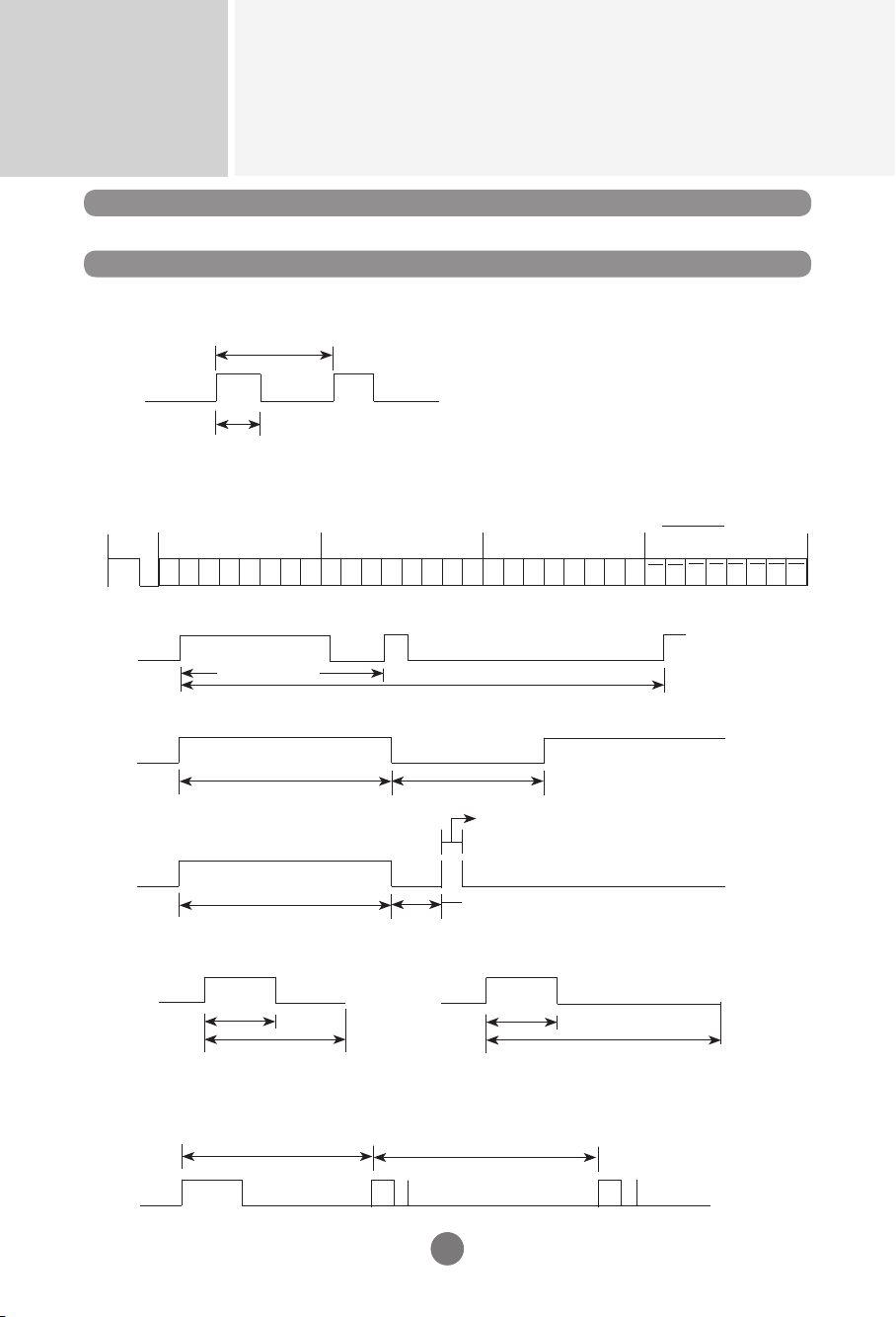
IR Codes
RS-232C
A12
Remote Control IR Code
How to connect
► Output waveform
single pulse, modulated with 37.917 kHz signal at 455 kHz
► Connect your wired remote control to Remote Control port on the Product.
► Configuration of frame
T1
Tc
▪
Repeat frame
Tf
Repeat code
► Repeat code
2.25 ms
9 ms
0.55 ms
► Frame interval : Tf
Tf
Tf
Tf = 108 ms @ 455 kHz
Lead
code
Low
custom code
High
custom code
Data code
Data code
C0 C1 C2 C3 C4 C5 C6 C7 C0 C1 C2 C3 C4 C5 C6 C7 D0 D1 D2 D3 D4 D5 D6 D7 D0 D1 D2 D3 D4 D5 D6 D7
► Lead code
9 ms
4.5 ms
Carrier frequency
FCAR = 1 / Tc = fosc / 12
Duty ratio = T1 / Tc = 1 / 3
▪
1st frame
► Bit description
0.56 ms
1.12 ms
0.56 ms
2.24 ms
▪
Bit "0"
▪
Bit "1"
▪
The waveform is transmitted as long as a key is depressed.

Controlling the Multiple Product
RS-232C
A13
IR Codes
RS-232C
A13
Code(Hexa) Function Note
1 08H
POWER Soft Power On/Off
2 0BH
INPUT Input Source Select Menu Open
3 0EH
SLEEP Sleep Time Control
4 0DH
ARC Aspect Ratio Correction. (Top, Bottom, Stretch)
5 54H
AUTO Auto Configuration (RGB Input Only)
6 10H
0 R/C Button
7 11H
1 R/C Button
8 12H
2 R/C Button
9 13H
3 R/C Button
10 14H
4 R/C Button
11 15H
5 R/C Button
12 16H
6 R/C Button
13 17H
7 R/C Button
14 18H
8 R/C Button
15 19H
9 R/C Button
16 43H
MENU Main Menu On/Off
17 5BH
EXIT Menu Exit
18 00H
Up(▲) Menu Navigation
19 01H
Down(▼) Menu Navigation
20 03H
Left(◄) Decrement Value, Select menu item
21 02H
Right(►) Increment Value, Select menu item

WARNING -This is a class A product. In a do-
mestic environment this product may cause
radio interference in which case the user may
be required to take adequate measures.
Warranty void if removed.
Important
WARRANTY VOID
IF REMOVED
3850TAZ209Y
Make sure to read the Safety Precautions
before using the product.
Keep the Owner ’s Manual(CD) in an
accessible place for furture reference.
The model and serial number of the SET
is located on the back and one side of the
SET. Record it below should you ever need
service.
MODEL
SERIAL
Temporary noise is normal when powering
ON or OFF this device.