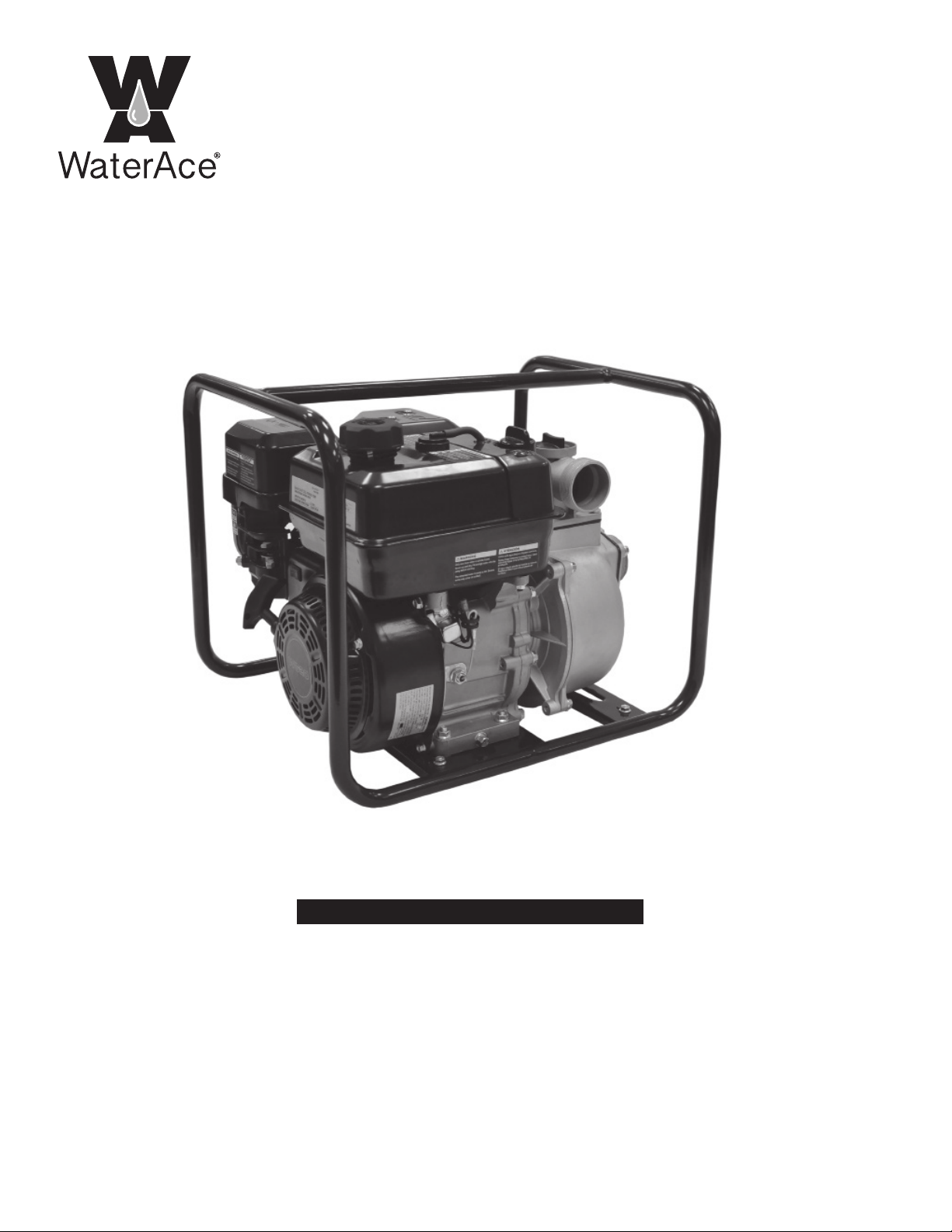
Owner’s Manual
WA20GEUP
Gasoline Engine
Self-Priming Pump
General Safety . . . . . . . . . . . . . . . . . . . . 2
Pre-Installation . . . . . . . . . . . . . . . . . . . . 3
Installation. . . . . . . . . . . . . . . . . . . . 4 & 5
Operation . . . . . . . . . . . . . . . . . . . . 5 to 8
Repair and Maintenance . . . . . . . . 9 to 11
Troubleshooting . . . . . . . . . . . . . . . . . . .12
Service Parts . . . . . . . . . . . . . . . . . . . . .13
Warranty . . . . . . . . . . . . . . . . . . . . . . . . 14
TABLE OF CONTENTS
A pump is designed to
operate in inherently wet environments.
ALWAYS USE EXTREME CAUTION
when installing or maintaining this product!
Need Help: Call 1-844-394-2604 for assistance;
Do Not Return to Store
Important Safety Instructions
Carefully read and follow all safety
instructions in this manual and on pump.
SAVE THESE INSTRUCTIONS – This manual
contains important instructions that should be
followed during installation, operation, and
maintenance of the product.
Save this manual for future reference.
Safety Labels
This is the safety alert symbol. When you
see this symbol on your pump or in this manual,
look for one of the following signal words and be
alert to the potential for personal injury!
Indicates a hazard which, if
not avoided, will result in death or serious injury.
Indicates a hazard which,
if not avoided, could result in death or serious
injury.
Indicates a hazard which, if
not avoided, could result in minor or moderate
injury.
NOTICE indicates practices not related to
personal injury.
Keep safety labels in good condition. Replace
missing or damaged safety labels.
General Safety
Risk of burns. Do not
touch an operating motor. Motors are de-
signed to operate at high temperatures. To
avoid burns when servicing pump, allow it to
cool for 20 minutes after shut-down before
handling.
Do not allow pump or any system compo-
nent to freeze. To do so will void warranty.
Pump water only with this pump.
Periodically inspect pump and system com-
ponents.
Wear safety glasses at all times when work-
ing on pumps.
Risk of explosion. Pump
body may explode if used as a booster
pump.
2
GENERAL SAFETY
STOP
Before you start
3
APPLICATIONS
The pump is a clean water pump and cannot pump sewage and seawater. Avoid silt, oil stain or other pollution liquid
which will cause corrosion of the parts.
TOOLS REQUIRED
Flathead and Phillips Screwdrivers
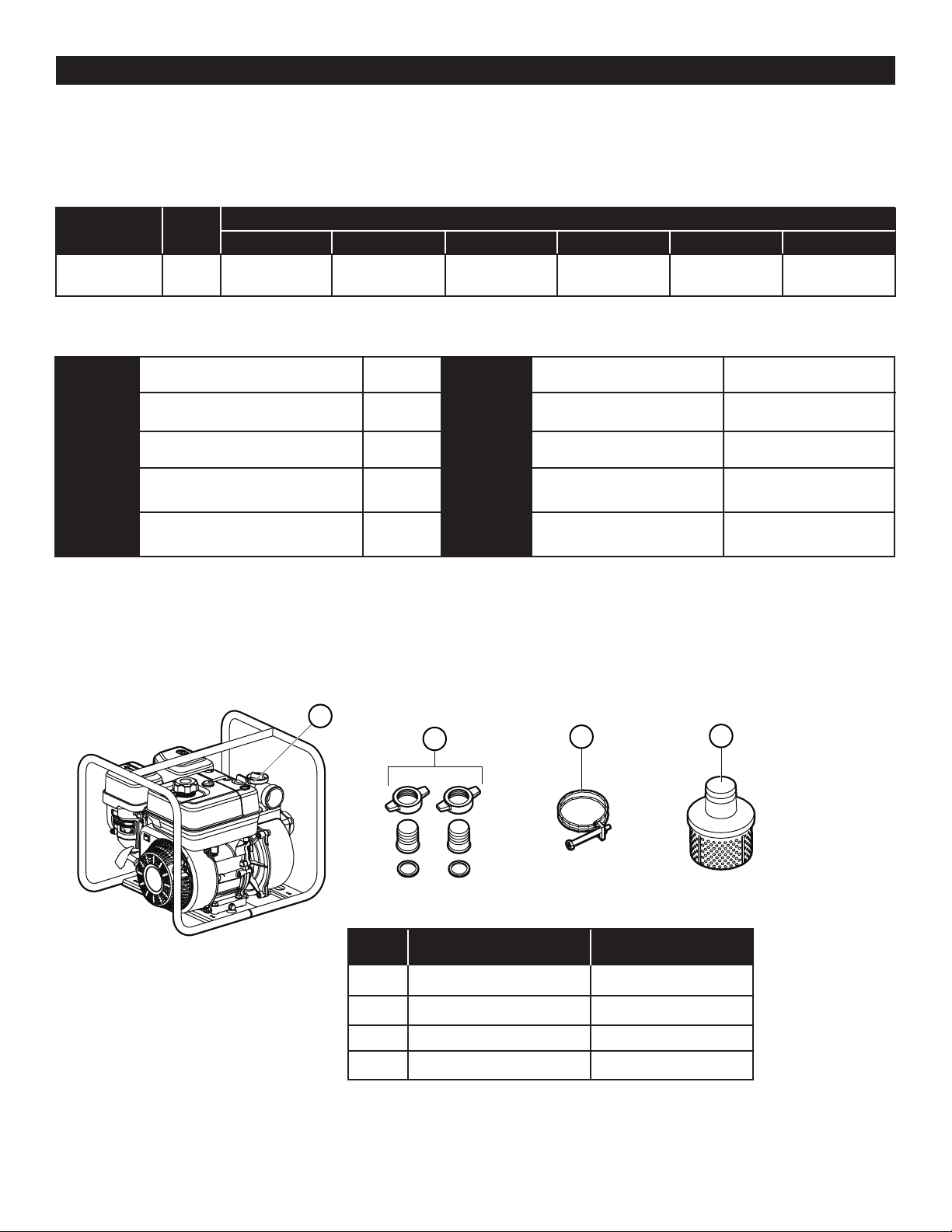
PACKAGE CONTENTS
PRE-INSTALLATION
PERFORMANCE
MODEL HP GPH of water @ Total Feet of Lift Max. Lift
0’ 20’ 40’ 60’ 80’
WA20GEUP 5-1/2 9000 7800 6300 4500 1800 90 ft.
SPECIFICATIONS
Pump Suction port diameter (in.) G2 in. Engine Model GH210-3
Discharge port diameter (in.) G2 in. Type Air-cooled, 4-stroke
Suction Head Lift (ft.) 20 Displacement (cc) 208
Total Head Lift (ft.) 90 Rated Output (kW-r/min) 4/3600
Discharge Capacity (GPH) 9000 Ignition System Transistor Magneto
A
BCBC D
A
B
C
D
PART DESCRIPTION QUANTITY
A Pump 1
B Joint Assembly 2 Sets
C Clamp 3
D Stainer 1
4
INSTALLATION
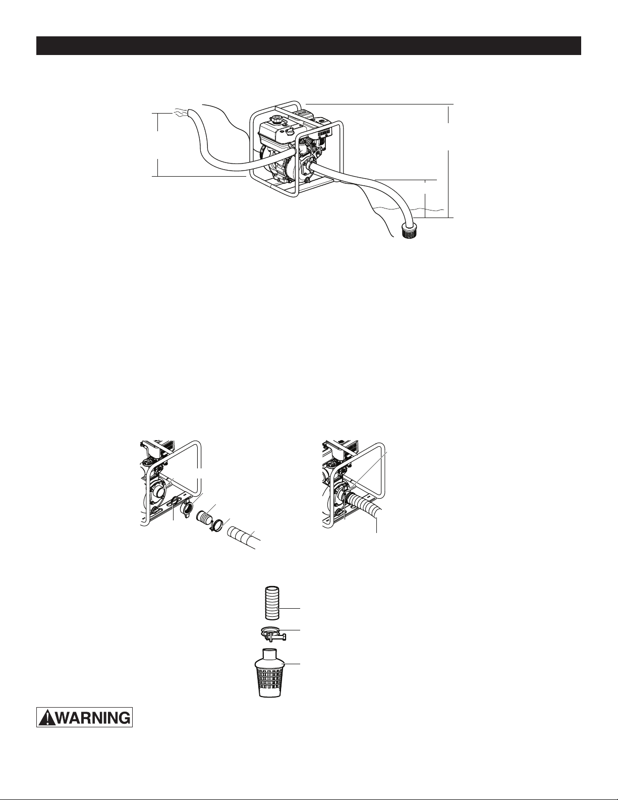
1. Place the unit as close to the water source as possible to minimize suction lift, obtain the best pumping
performance and aid in priming.
DISCHARGE HEAD
TOTAL HEAD
(26M 85FT)
SUCTION HEAD
FIGURE 1 - Typical Installation
2. For a permanent installation, mount the unit on a foundation that will support the weight of the pump and engine
and also provide stability while the pump is running. For most permanent installations, it is advisable to bolt the unit
directly to the foundation.
NOTE: Setting and/or shifting during operation can cause piping to place excessive strain on the pump and may
damage the pump case. Set the pump on a hard level surface.
3. Connect suction hose (not included) to the pump suction. The hose must be rated to hold the suction pressure and
prevent collapse while the pump is running.
4. Make the suction hose a continuous rise from the water source to the pump. High spots can trap air and also
make priming difficult. Make sure all connections are tight and free of air leaks.
NOTE: Suction hose must be at least as large as the pump suction port in order for the pump to operate properly.
5. Install the strainer (provided with the pump) on the other end of the suction hose and secure it with a hose clamp.
NEVER OPERATE THE PUMP WITHOUT THE STRAINER INSTALLED.
SUCTION HOSE
SUCTION HOSE
HOSE CONNECTOR
CLAMP
CLAMP
JOINT
PIPE JOINT
WASHER
SUCTION PORT
SUCTION HOSE
CLAMP
STRAINER
5
INSTALLATION
OPERATION
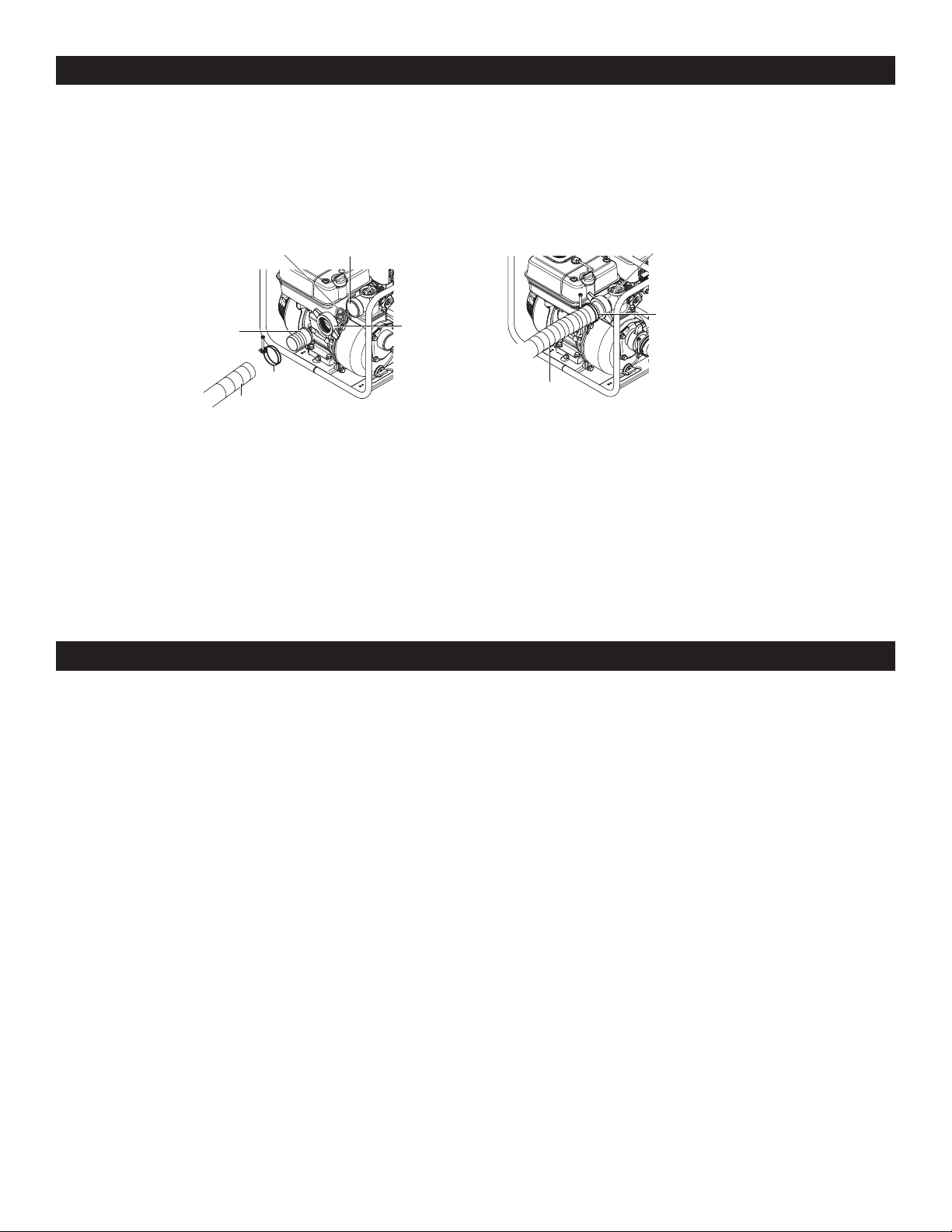
6. Connect discharge hose (not included) to the pump discharge port. It is best to use a short, large-diameter hose,
becausethiswillreduceuidfrictionandimprovepumpperformance.Alongorsmall-diameterhosewillincrease
uidfrictionandreducepumpoutput.
7. Tighten the clamp securely to prevent the discharge hose from disconnecting under high pressure.
INSTALLATION REQUIREMENTS
• Use reinforced hose to make the suction connection.
• Hose must be strong enough to not collapse during operation.
• Suction screen area must be at least four times suction pipe area.
• All suction hose must slope up toward suction port.
• Supportthehoseandttingstoreducestrainonthepumpcase.
• Depth of suction port must be at least (4) times the diameter of the suction hose to avoid forming vortexes....
EXAMPLE: 2” Pipe x 4 = 8” minimum depth.
NOTE: Do not start or run the pump dry or damage to the mechanical seal will result.
NOTE: Add engine oil before startup.
1. Aself-primingpumponlyneedstobemanuallyprimedattherststart.Onceprimed,undernormalconditions
the pump will reprime automatically at each subsequent start-up. If the pump is used in portable applications and
the water has been drained from the pump case, re-prime before start-up.
2. Toprime,removethewaterlterplug6(seepage6)fromthetopdischargeportandllthepumpwithwater.
Replace the plug and start the pump. The pump will require a few minutes to evacuate air from the suction line.
After several minutes of operation, the pump will be fully primed and pumping water. Priming time will vary
depending on the length and diameter of the suction line.
3. Refer to the BEFORE YOU START THE ENGINE and ENGINE OPERATIONS sections of this manual for starting
and operating instructions.
CLAMP
DISCHARGE
HOSE
HOSE CONNECTOR
DISCHARGE
PORT
DISCHARGE
HOSE
PIPE JOINT
CLAMP
JOINT
WASHER
6
OPERATION
BEFORE STARTING THE ENGINE
5
4
3
2
8
10
7
11
1
9
6
1
2
3
4
5
6
7
8
9
10
11
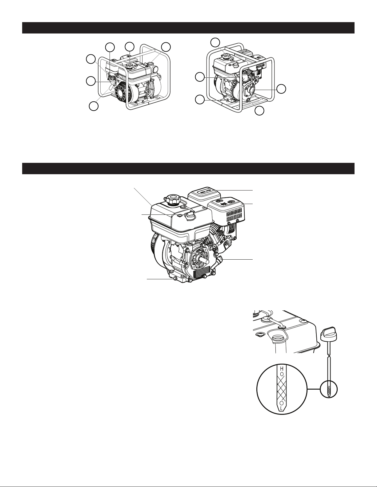
1. RECOIL STARTER GRIP 4. CHOKE LEVER 7. OIL DRAIN PLUG 10. SUCTION PORT
2. IGNITION SWITCH 5. FUEL CAP 8. DISCHARGE PORT 11. PUMP DRAIN CAP
3. FUEL VALVE LEVER 6. PRIMING WATER 9. OIL FILL & DIPSTICK
FILLER PLUG
Air filter
Gas tank
Oil drain plug
Muffler
Oil plug
GAS TANK
AIR FILTER
MUFFLER
OIL PLUG
OIL DRAIN PLUG
OIL FILL & DIPSTICK
CHECKING AND FILLING THE OIL
Theengineisshippedwithoutoil.Itmustbelledbeforestartingengine.
1.Filloilbyremovingthellcapanddipstick.Wipeoanyexcessoilfrom
the dipstick.
2. Add oil until the level reaches the bottom of the opening.
3.Checktheoillevelbypushingthecleaneddipstickintotheoilllopening.
DO NOT SCREW IT IN. Remove the dipstick and inspect it.
Add oil if needed.
4. Reinstall the cap and dipstick.
Oil capacity is 0.63 quarts (0.6 liter). Under normal conditions use 10W-30 oil.
Use 10W-40 oil if the engine is to be run in temperatures over 90ºF (32ºC). The
engine has a low-oil monitoring system. If the oil level drops too low, the system
willautomaticallyturnotheengine.
7
BEFORE STARTING THE ENGINE
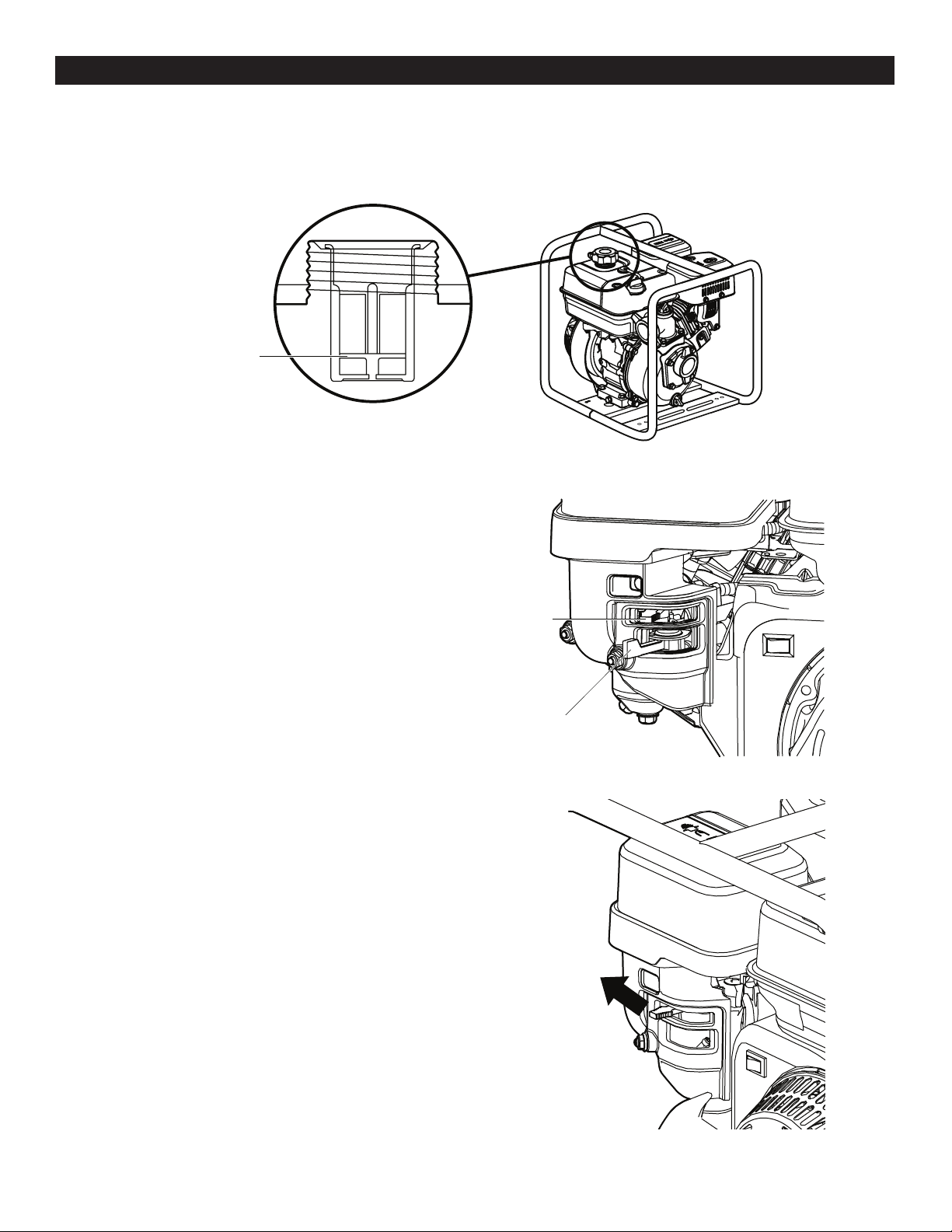
ADDING GASOLINE
Removethefuelcapandllthetankwithcleanfreshgasoline.Thisshouldbeunleadedfuelthathasanoctane
ratingof86orhigher.Donotllthetanktooverowing.Cleanupanyspilledgasolinebeforestartingengine.
OPENING THE FUEL VALVE
Move the fuel valve lever to the right to allow fuel to the engine.
CLOSING THE CHOKE
When starting a cold engine, move the choke lever to the left (closed) As
the engine warms up move it towards the right (open).
A warm engine should start with the choke open.
HIGHEST LEVEL
CHOKE LEVER
FUEL VALVE LEVER
8
ENGINE OPERATION
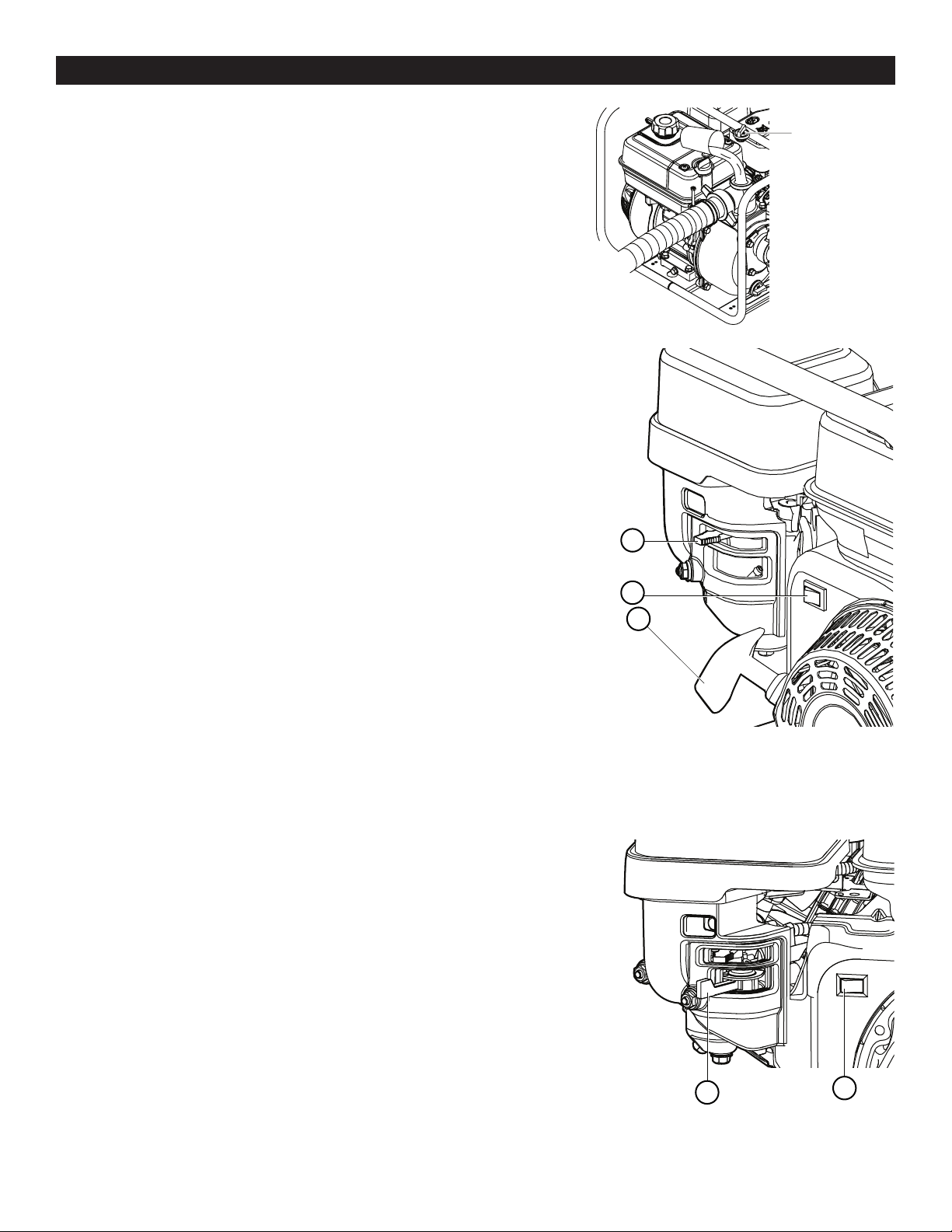
FILL WATER
Beforestartingtheengine,removethellerplugfromthepumpchamber
andcompletelyllthepumpchamberwithwater.Reinstallthellerplug
and tighten it securely.
TURNING THE ENGINE ON
• The ignition switch (1) controls the ignition. Move it to the ON position to start
the engine. The same control is used to stop the engine.
• Adjust the choke lever (3).
• Pull the recoil starter grip (2) on the recoil starter.
NOTE: Before starting a cold engine, you MUST move the choke lever (3) to
the left (closed). As the engine warms up, move it towards the right (open).
A warm engine should start with the choke open.
STOPPING THE ENGINE
• Stop the engine by turning the ignition switch (1) to OFF.
• Move the fuel valve lever (2) to OFF (left).
3
1
2
12
1
1
2
FILLER PLUG
1
2
3

9
REPAIR AND MAINTENANCE
Adjust and maintain the gasoline engine strictly in accordance with the maintenance methods and instructions listed in
this manual
DAILY MAINTENANCE
The regular inspection and adjustment must be carried out to ensure the gasoline engine maintains its excellent per-
formance. The regular maintenance also ensures a prolonged service life. See the table below for maintenance cycle.
NOTES:
Indicatesmaintenanceintervalofspecicitems.
Indicatesmaintenancetobecarriedoutafterrstoperation.
With respect to gasoline engines for commercial purposes and under long-term operation, their maintenance intervals
shall bee appropriately determined.
a. Increases the maintenance interval if it is used in a dusty area.
b. The maintenance of these items shall be conducted by maintenance service stations, unless the users have
appropriate tools and the maintenance ability.
MAINTENANCE CYCLE
ITEM EACH TIME EVERY 1 EVERY 3 EVERY 6 EVERY 1 YEAR EVERY 2 YEARS
OF USE MONTH OR MONTHS OR MONTHS OR OR 100 HOURS OR 200 HOURS
10 HOURS 20 HOURS 50 HOURS
Lubricating Check
Oil Oil Level
Replacement
Air Filter Check
Cleaning
Spark Plug Check and
Adjustment
Replacement
Spark Cleaning
Extinguisher
(optical part)
Bolt, nut & Check Screwing up if necessary
other
fasteners
Coolingn Check
Max. Check &
no-load Adjustment
speed
Valve Check &
Clearance Adjustment
Combustion Cleaning 200 Hours Later
Chamber
Fuel Srainer Check
Fuel Tank Check
Fuel Pipe Check Every 2 Years (replace when necessary)
n
n
n
n
n
n
n
n
n
n
n
n
q
b
b
b
b
b
a
q
n
10
REPAIR AND MAINTENANCE
REPLACEMENT OF LUBRICATING OIL
Runthepumpwithwaterforve(5)minutesandthenshutitdownbeforereplacingtheengine’slubricatingoil.This
ensures the quick and complete release of the lubricating oil.
MAINTENANCE OF AIR FILTER
Thefunctionoftheairlteristoltrateimpuritiesanddustintheairsoastomixcleanairwithfuelforthesakeof
stableengineperformance.Thedirtyairlterwillmaketheimpuritiesandoilstainscovertheelementoftheairlter,
reduce the air capacity required by the combustion of gasoline engine and cause the disproportion of gas mixture,
abnormal combustion and engine performance attenuation.
DO NOT USE GASOLINE OR CLEANING AGENT WITH LOW IGNITION POINT TO CLEAN THE FILTERING
ELEMENT OF THE AIR FILTER, AS A FIRE OR EXPLOSION MAY OCCUR.
IT IS STRICTLY PROHIBITED TO OPERATE THE GASOLINE ENGINE IN THE CASE OF NOT INSTALLING THE FIL-
TERING ELEMENT OF THE AIR FILTER AS IT MAY ACCELERATE THE WEAR AND DAMAGE OF THE GASOLINE
ENGINE.
SOME SOLID IMPURITIES OF HIGH HARDNESS DIRECTLY INTO THE COMBUSTION CHAMBER OF THE
ENGINE WILL CAUSE IRRETRIEVABLE FATAL DAMAGE TO THE ENGINE. THEREFORE, THE MAINTENANCE
FREQUENCY SHALL BE INCREASED IF THE ENGINE IS USED AT A PLACE WITH HIGH DUST CONTENT.
o Check if the oil tank cover is tightened.
o Unscrew the engine oil plug and tilt the engine
towards the cylinder head cover, drain the oil
into an appropriate container and then screw up the
engine oil plug.
o Unscrewtheoilllanddipstick,lltherecommended
lubricatingoilthroughtheoilllerandcheckthe
oil level (no more than 600 ml)
o It is recommended to replace the lubricating oil when there is no or little fuel in the fuel tank in case the fuel
overowingfromthefueltankwhentheengineistilted.
o Incaseoflubricatingoiloverowing,makesuretowipeotheoil.Washhandswithsoapandwaterordetergent
after contacting the lubricating oil, and then wash hands with clean water.
o Please dispose the waste lubricating oil and containers with methods in compliance with environmental protection
requirements. It is suggested to store the waste lubricating oil into a sealed container and deliver it to the local
waste oil recycle bin for treatment. It is forbidden to directly throw into the dustbin or pour it into water drain.
ENGINE OIL PLUG
AIR CLEANER COVER
FOAM FILTER ELEMENT
PAPER FILTER ELEMENT
AIR CLEANER BASE
PRECAUTIONS:
o Theairlteroftheengineisofadouble-elementstructure(foam+paper).
Forthepurposeofinspection,removetheairltercasingandtakeoutthe
lterelement.Thedamagedlterelementshallbedulyreplacedand
usually replaced once during maintenance.
o CLEANING THE FOAM FILTER ELEMENT:Washthefoamlterelement
with cleaning agent, swish it after cleaning with fresh water, and air dry
before operation.
o CLEANING THE PAPER FILTER ELEMENT: Lightly
beatthelterelementseveraltimes,andblowairfrom
inside to the outside with compressed air (nor exceeding
30 psi). Never use items such as a brush to clean the
paperlterelement.
11
REPAIR AND MAINTENANCE
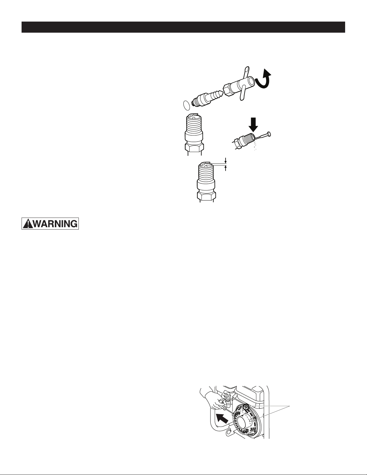
MAINTENANCE OF SPARK PLUG (MODEL F6RTC)
To ensure the normal operation of the engine, ensure the spark plug is always clean and properly adjusted as the
steps below show:
1. Remove the spark plug by twisting counterclockwise.
2. Gently remove any carbon deposits from the plug.
3. Ensure the clearance is between 0.6~0.8mm.
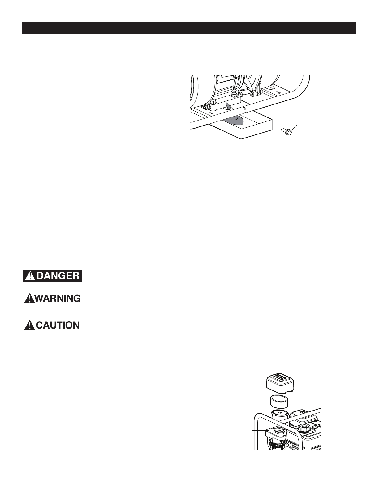
MAINTENANCE BEFORE A LONG-TERM SHUTDOWN
If the engine will not be used for a long period of time, perform the following maintenance steps on the engine before
shutdown:
1. Unscrew the fuel switch, unscrew the oil drain bolt at the bottom of the carburetor, and tighten the bolt after
complete release of fuel in the tank and carburetor.
2. Unscrew the oil drain bolt at the bottom or the crankcase to completely release the lubricating oil in the crank
case, and then tighten the oil drain bolt.
3. Perform the following maintenance steps on the engine cylinder:
o Remove spark plug
o Pour a teaspoon (5cc) of clean engine oil into the cylinder.
o Pull the start handle several times to distribute the oil in the cylinder.
o Reinstall the spark plug.
o Pull the handle slowly until resistance is felt and the notch on the starter pulley aligns with the hole at the
top of the recoil starter cover. This will close the valves so moisture cannot enter the engine cylinder.
Return the start handle gently.
4.Wipeotheoilstainanddustontheexternalsurfacewith
a cleaning cloth and remove the dirt between the
coolingns,soastokeepthegasolineengineclean.
After cleaning, store the engine in a clean, dry and
ventilated location.
THE SPARK PLUG MUST BE SECURELY TIGHTENED IN THE ENGINE. OTHERWISE, THE COMBUSTION
CHAMBER WILL NOT BE AIRTIGHT DURING OPERATION. THE LEAKAGE OF COMPRESSED AIR WILL REDUCE
ENGINE POWER AND SERIOUS LEAKAGE WILL LEAD TO ENGINE FAILURE.
0.6~0.8 mm
r.
0.6~0.8mm.
Align the notch on the
pulley with the hole at
the top of the cover
12
TROUBLESHOOTING
DONOTDISASSEMBLETHISPUMPWITHOUTTHEMANUFACTURER’SPERMISSION.THEWARRANTYDOES
NOT COVER UNAUTHORIZED DISASSEMBLY.
If the remedial actions in this table do not eliminate the faults or the faults encountered are unmentioned in this table,
please contact customer service.
PROBLEM PROBABLE CAUSE RESOLUTION
Theengineexperiences Fuelisinsucient Rellrecommendedfuel
dicultystartingup,does
On/Oswitchisnotturnedon. On/Oswitchisturnedto“On”
not start up, or does not
Choke is not closed. Close Choke.
producesucientpower.
Too much carbon deposit in spark plug Eliminate carbon deposit
Gapofsparkplugisnotcorrect. Adjustgapofsparkplugtospecied
range.
Spark plug is damaged. Replace spark plug.
Use engine oil of poor quality or Replace engine oil
engine oil deteriorates.
Overload or overheats. Check operating status.
Engineoilisinsucient. Addappropriatevolumeofengineoil.
Thepumpiseithernot Thereisblockageinthelter. Removetheblockage.
pumping water or there
Thereisinadequatepriminginthepump. Unscrewwaterllingplugandllwith
is not enough pressure
clean water.
when running.
Blockage, drop-out, leakage of water pipe, Check the water pipe.
ortoolongorinsucientdiameterofthe
pipe
Water suction does not sink into water Adjust the position of the water
suction, so that it is completely
submerged in water.
Water suction pipe joint leaks. Check water pipe joint.
The installation height of the water is Decrease the installation height of the
too high. water pump.
13
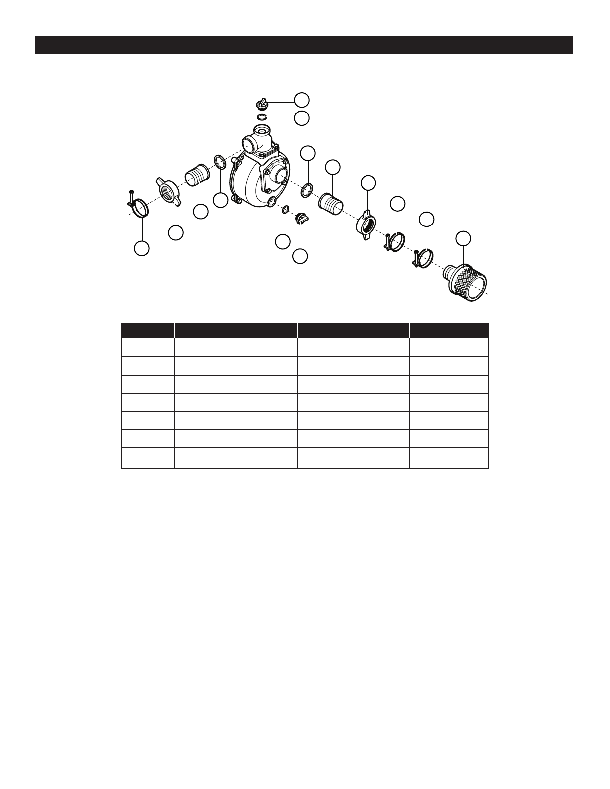
SERVICE PARTS
PART PART NUMBER NAME QUANTITY
1 100022246 Strainer 1
2 100022225 Clamp 3
3 100030202 Pipe Joint 2
4 100022201-0001 Joint 2
5 1000022187 Washer 2
6 100021938 Plug 2
7 100021965 O-ring 2
1
7
6
2
2
3
4
5
7
6
5
4
3
2

14
Retain Original Purchase Receipt for Warranty Eligibility
Limited Warranty
Manufacturer warrants to the original consumer purchaser (“Purchaser” or “You”) that its products are free from defects in
material and workmanship for a period of twelve (12) months from the date of the original consumer purchase. If, within
twelve (12) months from the original consumer purchase, any such product shall prove to be defective, it shall be repaired
or replaced at manufacturer’s option, subject to the terms and conditions set forth herein. Note that this limited warranty
applies to manufacturing defects only and not to ordinary wear and tear. All mechanical devices need periodic parts and
service to perform well. This limited warranty does not cover repair when normal use has exhausted the life of a part or
the equipment.
The original purchase receipt and product warranty information label are required to determine warranty eligibility. Eligibil-
ity is based on purchase date or original product – not the date of replacement under warranty. The warranty is limited to
repair or replacement of original purchased product only, not replacement product (i.e. one warranty replacement allowed
per purchase).
Purchaser pays all removal, installation, labor, shipping, and incidental charges.
Claims made under this warranty shall be made by returning the product to the retail outlet where it was purchased or to
the factory immediately after the discovery or any alleged defect. Manufacturer will subsequently take corrective action as
promptly as reasonably possible. No requests for service will be accepted if received more than 30 days after the warranty
expires. Warranty is not transferable and does not apply to products used in commercial/rental applications.
General Terms and Conditions; Limitations of Remedies
You must pay all labor and shipping charges necessary to replace product covered by this warranty. This warranty does
not apply to the following: (1) acts of God; (2) products which, in manufacturer’s sole judgment, have been subject to
negligence, abuse, accident, misapplication, tampering, or alteration; (3) failures due to improper installation, operation,
maintenance or storage; (4) atypical or unapproved application, use or service; (5) failures caused by corrosion, rust or
other foreign materials in the system, or operation at pressures in excess of recommended maximums.
This warranty sets forth manufacturer’s sole obligation and purchaser’s exclusive remedy for defective products.
MANUFACTURER SHALL NOT BE LIABLE FOR ANY CONSEQUENTIAL, INCIDENTAL, OR CONTINGENT DAMAGES
WHATSOEVER. THE FOREGOING LIMITED WARRANTIES ARE EXCLUSIVE AND IN LIEU OF ALL OTHER EXPRESS
AND IMPLIED WARRANTIES, INCLUDING BUT NOT LIMITED TO IMPLIED WARRANTIES OF MERCHANTABILITY
AND FITNESS FOR A PARTICULAR PURPOSE. THE FOREGOING LIMITED WARRANTIES SHALL NOT EXTEND
BEYOND THE DURATION PROVIDED HEREIN.
Some states do not allow the exclusion or limitation of incidental or consequential damages or limitations on how long an
implied warranty lasts, so the above limitations or exclusions may not apply to You. This warranty gives You specic legal
rights and You may also have other rights which vary from state to state.
WARRANTY
1899 Cottage Street
Ashland, Ohio 44805
Telephone: 1-844-394-2604