Loading ...
Loading ...
Loading ...
14
ENGLISH
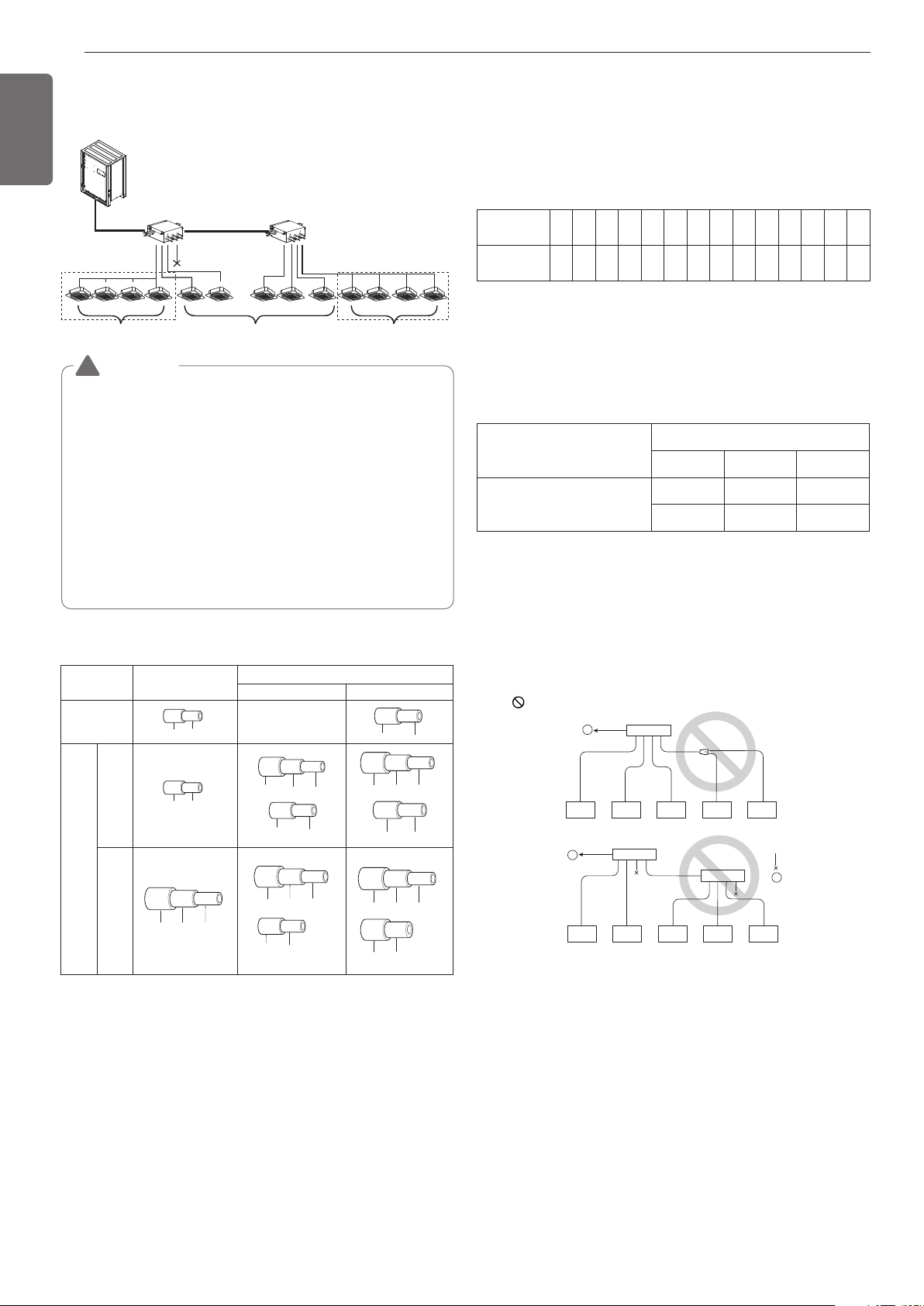
HR unit HR unit
sealing
Changeover under control Auto changeover Changeover under control
Zoning control group 1 Zoning control group 2
(Max. 8 Indoor Units)
(Max. 8 Indoor Units)
WARNING
• A branch pipe of HR unit allows up to 14.5kW(48kBtu/h) based on
cooling capacity of the indoor unit. (up to 14.5kW(48kBtu/h) for
max installation)
• The maximum total capacity of indoor units connected to a
PRHR041 HR unit is 58kW(192kBtu/h).
• The maximum number of indoor units connected to a PRHR041
HR unit are 32 indoor units. (The Maximum indoor units per a
branch pipe of HR unit are 8 indoor units)
• There is not operate “Auto-changeover” & “Mode override” func-
tion in the zoning group.
• When there are operating indoor units on cooling(heating) mode,
another indoor units aren’t changed on heating(cooling) mode in
the zoning group.
!
Installation of Zoning Control
Some indoor unit can be connected to one port of HR unit.
[Reducers for indoor unit and HR unit]
(Unit : mm)
Models
High pressure
–
Gas pipe
Low pressure
Liquid pipe
Indoor unit
reducer
HR unit
reducer
PRHR021A
OD22.2(7/8) Ø19.05(3/4) Ø15.88(5/8)
OD15.88(5/8) Ø
12.7(1/2)
Ø6.35(1/4)OD9.52(3/8)
Ø6.35(1/4)OD9.52(3/8)
OD19.05(3/4) Ø15.88(5/8)
OD12.7(1/2) Ø9.52(3/8)
Ø12.7(1/2)
OD22.2(7/8) Ø19.05(3/4) Ø15.88(5/8)
OD15.88(5/8) Ø12.7(1/2)
PRHR031A/
PRHR041A
OD19.05(3/4) Ø15.88(5/8)
OD28.58(1-1/8) Ø22.2(7/8) Ø19.05(3/4)
OD15.88(5/8) Ø12.7(1/2) Ø9.52(3/8)
OD15.88(5/8) Ø12.7(1/2)
CAUTION
1 Use the following materials for refrigerant piping.
• Material: Seamless phosphorous deoxidized copper pipe
• Wall thickness : Comply with the relevant local and national regu-
lations for the designed pressure
3.8MPa(551.14psi). We recommend the follow-
ing table as the minimum wall thickness.
2 Commercially available piping often contains dust and other materi-
als. Always blow it clean with a dry inert gas.
3 Use care to prevent dust, water or other contaminants from enter-
ing the piping during installation.
4 Reduce the number of bending portions as much as possible, and
make bending radius as big as possible.
5 Always use the branch piping set shown below, which are sold sep-
arately.
Outer diameter
[mm(inch)]
6.35
(1/4)
9.52
(3/8)
12.7
(1/2)
15.88
(5/8)
19.05
(3/4)
22.2
(7/8)
25.4
(1)
28.58
(1-1/8)
31.8
(1-1/4)
34.9
(1-3/8)
38.1
(1-1/2)
41.3
(1-5/8)
44.45
(1-3/4)
53.98
(2-1/8)
Minimum thickness
[mm(inch)]
0.8
(1/32)
0.8
(1/32)
0.8
(1/32)
0.99
(5/128)
0.99
(5/128)
0.99
(5/128)
0.99
(5/128)
0.99
(5/128)
1.1
(3/64)
1.21
(3/64)
1.35
(7/128)
1.43
(7/128)
1.55
(1/16)
2.1
(11/128)
Y branch
Header
4 branch 7 branch 10 branch
ARBLB01621, ARBLB03321,
ARBLB07121, ARBLB14521,
ARBLB23220
ARBL054 ARBL057 ARBL1010
ARBL104 ARBL107 ARBL2010
6 If the diameters of the branch piping of the designated refrigerant
piping differs, use a pipe cutter to cut the connecting section and
then use an adapter for connecting different diameters to connect
the piping.
7 Always observe the restrictions on the refrigerant piping (such as
rated length, difference in height, and piping diameter).
Failure to do so can result in equipment failure or a decline in heat-
ing/cooling performance.
9 The Multi V water will stop due to an abnormality like excessive or
insufficient refrigerant. At such a time, always properly charge the
unit. When servicing, always check the notes concerning both the
piping length and the amount of additional refrigerant.
10 Never perform a pump down. This will not only damage the com-
pressor but also deteriorate the performance.
11 Never use refrigerant to perform an air purge. Always evacuate
using a vacuum pump.
12. Always insulate the piping properly. Insufficient insulation will re-
sult in a decline in heating/cooling performance, drip of condensate
and other such problems.
13. When connecting the refrigerant piping, make sure the service
valves of the Outside Unit is completely closed (the factory setting)
and do not operate it until the refrigerant piping for the Outside and
Indoor Units has been connected, a refrigerant leakage test has
been performed and the evacuation process has been completed.
Ⓐ To Outside Unit
Ⓑ Sealed Piping
8 A second branch cannot be made after a header. (These are shown
by .)
A
A
B
Loading ...
Loading ...
Loading ...