
Loading ...
Loading ...
Loading ...
8 | JL Audio - MHD900/5 Owner’s Manual
9
amPliFier inPuts
The MHD900/5 has three separate input
sections, one for the “Front” left and right
channels, another for the “Rear” left and
right channels and one for the Subwoofer
Channel. Each section consists of a pair of
RCA-type input jacks on the Connection
Panel of the amplifier and input controls on
the Control Panel of the amplifier: a single
“Input Voltage” switch, an “Input Mode”
switch and three individual “Input Sens.”
rotary controls (one in each channel section).
“inPut mode” switCH
The “Input Mode” switch is located under
the “General Setup” heading at the far right of
the control panel. This switch allows operation
of all five amplifier channels with only one pair
of input signals (2 ch.) or with independent front
and rear input signal pairs (4 ch.) or with discrete
front, rear and subwoofer signal pairs (6 ch.).
“6 Ch.” input mode
In this mode, you will connect separate pairs
of input cables to the “Front”, “Rear” and “Sub”
amplifier inputs, allowing you full channel
control from the source unit. If the source unit
only provides a mono (single) subwoofer output,
use a y-adaptor cable to feed both the “Left” and
“Right” subwoofer inputs of the MHD900/5 with
the mono signal. Failure to do so will result in
reduced gain and possible distortion.
“4 Ch.” input mode
In this mode, you will connect separate
pairs of input cables to the “Front” and “Rear”
amplifier inputs and leave the “Sub” inputs
unused. The subwoofer channels will receive
signal from the sum of the signals at the “Front”
and “Rear” inputs so that front-to-rear fading of
the main channels does not significantly affect
the subwoofer level.
“2 Ch.” input mode
To operate all five channels of the MHD900/5
with a single pair of stereo inputs, select the
“2 Ch.” position on the “Input Mode” switch
and connect a single pair of input cables to the
“Front” input jacks only. The “Rear” and “Sub”
input jacks will remain unused. In this mode, the
amplifier will route the signals connected to the
“Front” inputs to the Front, Rear and Subwoofer
channels. Front-to-rear fading will not be available.
“input Voltage” switch
A wide range of signal input voltages can
be accommodated by each of the MHD900/5’s
differential-balanced inputs (200mV – 8V
RMS). This wide range is split up into two
sub-ranges, accessible via the “Input Voltage”
switch located next to the “Input Mode”
switch under the “General Setup” heading.
The “Low” position of the “Input Voltage”
switch selects an input sensitivity range between
200mV and 2V for all the amplifier channels. This
means that the “Input Sens.” rotary controls will
operate within that voltage window. If you are
using an aftermarket source unit, with preamp-
level outputs, this is most likely the position that
you will use (regardless of what voltage output
capability is claimed by the source unit).
The “High” position of the “Input Voltage”
switch selects an input sensitivity range between
800mV and 8V. This is for use with speaker-level
outputs from source units and small amplifiers
found in many OEM (factory-installed) systems.
To use speaker-level sources, splice the speaker
output wires of the source unit or small amplifier
onto a pair of RCA plugs for each input pair or use
the JL Audio ECS Speaker Wire to RCA adaptor
(XB-CLRAIC2-SW). It is not necessary (or
advisable) to use “Line Output Converters” with
your MHD900/5.
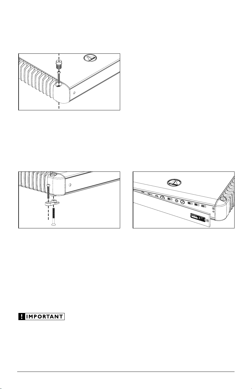
amPliFier mounting oPtions
The MHD900/5 has two mounting options to
ease in installation.
standard mounting
The standard method of mounting requires
removal of the four corner caps with the 4 mm
hex wrench included with your amplifier. Using
appropriate mounting screws (not included),
secure the amplifier in all four corners and
replace the corner caps to cover the screws.
lateral mounting Feet
Lateral Mounting Feet are also included
with your MHD900/5 to provide an alternative
mounting option. Each mounting foot
should be attached to the bottom of the
amplifier by screwing the provided bolt into
the bottom of the amplifier and up into the
corner cap with the supplied 2.5 mm hex
wrench. Next, using appropriate mounting
screws (not included), secure the amplifier
by its four Lateral Mounting Feet.
Check before drilling any holes in your vessel to
make sure that you will not be drilling through
a gas tank, brake line, wiring harness or other
vital vessel system.
Control Panel seCuritY CoVer
The MHD900/5 features a Control Panel
Security Cover. When installed, the cover ensures
that your amplifier settings are not accidentally
changed while creating a clean aesthetic for the
amplifier and your installation. The control panel
security cover is pre-installed at the factory and
must be temporarily removed for access to the
controls described throughout this manual.
The security cover is secured by a single 2.5
mm hex-head screw at the far right of the panel.
Loosen the hex-head screw to release the security
cover (it is not necessary to completely remove the
screw). To re-install the security cover once all
adjustments have been made, insert the tongue on
the cover’s left edge into the groove where the left-
side heatsink meets the control panel, hinge the
panel closed and secure the screw using the
supplied 2.5 mm hex wrench. Do not overtighten
the screw.
Loading ...
Loading ...
Loading ...