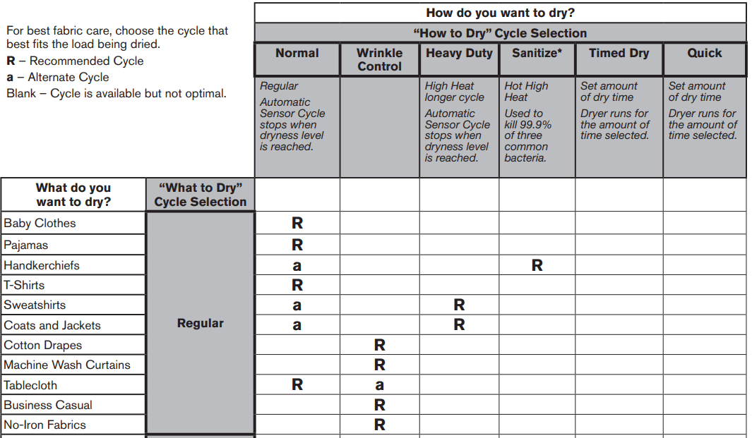
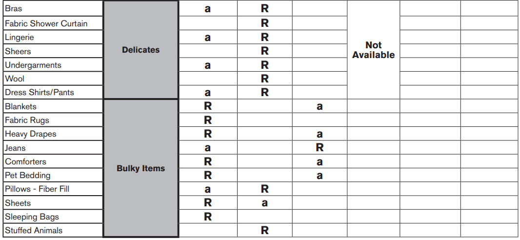
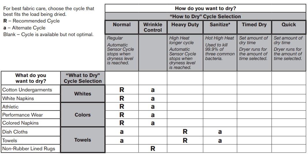
First select a cycle from the “What to Dry” and then select the “How to Dry” to get the best combination cycle available for the type of items you are going to dry. See “Cycle Guide” for cycle details.
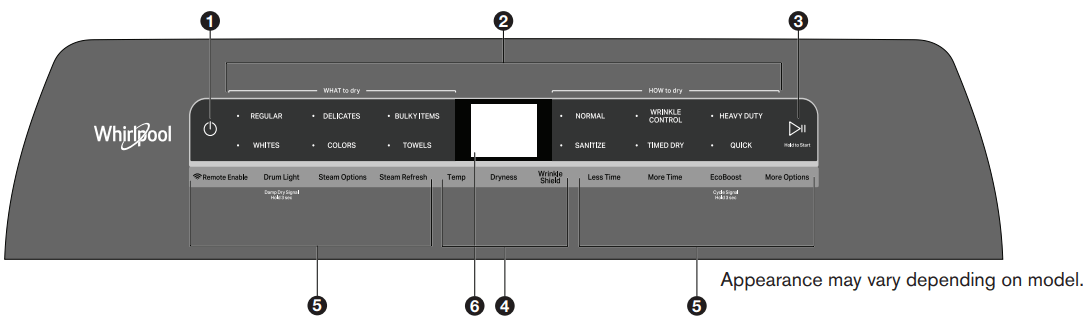
3. START/PAUSE
Touch and hold; cycle will start after countdown.
Touch START/PAUSE during a cycle to pause it. Touch again to resume.
4. MODIFIERS (Not all cycles and options are available on all models.)
NOTE: Dryer remembers the last completed cycle and cycle settings. The next time you turn dryer on, it will be set to run the last cycle.
Temp Touch to modify the cycle’s available temperatures (Air Only, Low, Medium, Medium High, High). Follow garment label instructions for best results. Once a cycle has started, the temperature can be changed within the first 5-8 minutes.
Dryness Touch to modify the cycle’s available dryness levels on the sensor cycles (Less, Normal, More). NOTE: Dryness is for use with Automatic Cycles only.
Wrinkle Shield™ Option Touch to turn on/off and on with steam (select models). Wrinkle Shield™ option adds up to 150 minutes of periodic tumbling and heat to help reduce wrinkling. Wrinkle Shield™ option with steam will add a short steam cycle after 60 minutes to help smooth wrinkles.
5. CYCLE OPTIONS (Not all cycles and options are available on all models.)
Use to select available modifiers for your dryer.
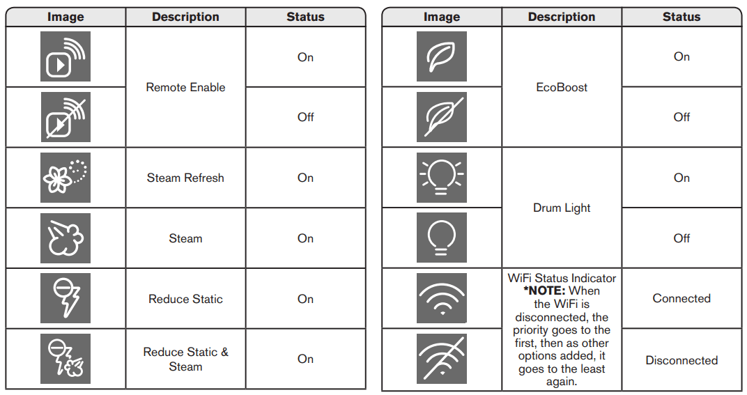
Remote Enable Touch each time you want to remotely control via the Whirlpool® app. Follow the instructions in the “GET THE WHIRLPOOL® APP AND GET CONNECTED” section below for more details.
NOTE: Once Remote Enable has been selected, certain interactions with the dryer will cause it to cancel Remote Enable. Example: Opening the door.
Damp Dry Signal Touch DAMP DRY SIGNAL or touch and hold DRUM LIGHT (depending on the model) for at least 3 seconds to turn the Damp Dry Signal on or off. You will get a sound and display notification as “Items are damp. You can pause and reposition for best results”.
Drum Light Touch to turn the drum light on/off.
Steam Options Touch to add Steam and/or Reduce Static to selected cycle. Steam option adds steam to the end of cycle to help smooth wrinkle. Reduce Static will automatically tumble, pause and introduce a small amount of moisture to the load to help reduce static.
Steam Refresh (steam models only) This cycle is best for reducing wrinkles from dry items. Cycle time will increase, depending on number of items. This is an independent cycle that cannot be combined with any other cycle.
More Time/Less Time Timed Dry Adjust Touch MORE TIME or LESS TIME with the Timed Dry/Quick Dry cycle to increase or decrease the length of the cycle time.
EcoBoostTM Option The EcoBoostTM option will default on only for the Regular/ Normal cycle and is only available on that cycle. This option allows you to increase your energy savings by using a slightly lower heat level. The EcoBoostTM option will increase drying times by approximately 40 minutes, which will be reflected on the LCD Display. If optimal time is desired, touch EcoBoost to turn off this option.
Cycle Signal Use this option to turn the signal indicating the end of a drying cycle to Low, Medium, High, or Off.
NOTE: Press/hold Cycle Signal to select the volume.
More Options Touch to select your “Favorite cycle” (Only available for models with WiFi capability). Favorite cycle: You may create “custom” cycles in the app and store one frequently-used or favorite cycle on the machine.
6. LCD DISPLAY
When you select a cycle, its default settings will display and the Estimated Time Remaining (for Automatic Cycles) will vary depending on “What to Dry” and “How to Dry” selections, or actual time remaining for Timed Dry cycles (for Manual Cycles) will be displayed.
CYCLE PHASE LABELS
Sensing Displays during Sensor cycles to indicate that the moisture sensor on the dryer is operating. It will not be displayed during Timed/Quick Dry cycles or options such as Wrinkle Shield™ option.
Drying Dryer is in the main dry phase of the automatic cycle. Steaming Steam option selected and Steam phase running.
Cool Down The dryer has finished drying with heat and is now tumbling the load without heat to cool it down.
Static Reduce Reduce Static phase is running.
End Display message will show “Drying is complete” and will timeout after 5 minutes. This will indicate that the selected cycle has ended and the load may be removed from the dryer. If Wrinkle Shield™ option has been selected, the dryer may continue to tumble the load, even if “End” is displayed.
Check Vent The Check Vent alert is a feature available for Automatic cycles only. This alert will show the status of airflow through the dryer and the dryer vent system for the dryer’s life. During the sensing phase at the beginning of the cycle if it detects a blocked vent or low pressure it will display “Check vent. Clean lint screen or vent for better performance.”
REMEMBER: The dryer will continue to operate even when check vent notification is displayed, but poor airflow can impact dry times and overall performance. Display message can be cleared by pressing any key with the exception of Power which will cancel the cycle.
USING YOUR DRYER
If you accidentally select wrong language during digital un-boxing and/or you want to get back to Factory settings then perform Factory Reset.
FACTORY RESET Press/hold both TEMP and Wrinkle Shield™ keys until display count-down has completed. Unit will power back on with “Select Language” display message.
*NOTE: See “Cycle Guide” for more information about cycles, settings, and options. Not all cycles, settings, and options are available with all models. Read all your Manuals for more information on your unit.
CYCLE GUIDE
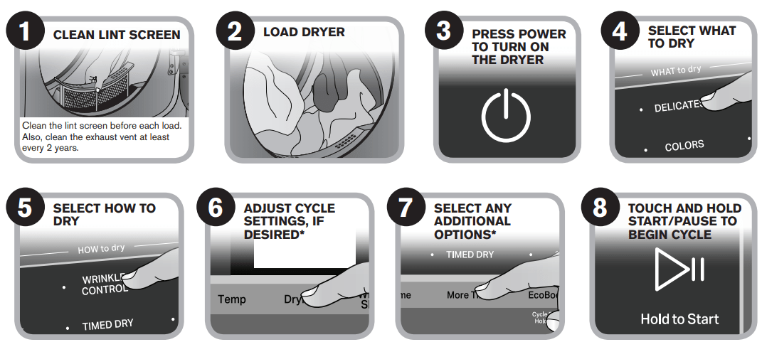
Your dryer has a unique user interface to help you select the best cycle you need for your load. The “What to Dry” “How to Dry” layout guides you to the optimal cycle in two easy steps:
First determine what items are in the load that you are trying to dry. Use that to guide your “What to Dry” selection.
Then determine how you want the dryer to dry them by selecting the appropriate “How to Dry” selection. Modifiers are preset for the items being dried, but can be changed if desired.
To get the most energy savings and enhanced fabric care from your dryer, use the Automatic cycles. These cycles measure the drying air temperature and moisture levels to turn the dryer off once the load reaches the selected dryness level. Dryer performance and results may vary with service voltage less than rated voltage (Electric, 240 V; Gas, 120 V).
* Extended high-heat drying cycle intended to help sanitize items such as sheets and towels. This cycle is not recommended for all fabrics. For best results, this cycle should be run to completion to ensure sanitization and do not interrupt cycle.
*Extended high-heat drying cycle intended to help sanitize items such as sheets and towels. This cycle is not recommended for all fabrics. For best results, this cycle should be run to completion to ensure sanitization and do not interrupt cycle.
Models 7120 & 8120
NOTE: These clothes dryer’s Government energy certifications were based on the Regular + Normal Cycle, Maximum Drying Temperature Setting, Normal Dryness Level, EcoBoostTM On. The as - shipped defaults of EcoBoostTM On, Wrinkle ShieldTM option off, Remote Enable off, were used.
Models 5100 & 6120
NOTE: These clothes dryer’s Government energy certifications were based on the Regular + Timed Dry Cycle and Maximum Drying Temperature Setting. The as - shipped defaults of EcoBoostTM On, Wrinkle ShieldTM option off, Remote Enable off, Normal Dryness level, were used.
DRYER ICONS
FAULTS AND ERROR CODES
Faults marked with “‡” will stop the cycle execution. If no action is taken within 5–10 minutes, the display will turn off. All faults can be viewed in the ‘Fault History’ section of Service Mode. Code Description E
Code
Description
Explanation and Recommended Procedure
F1E1
Main Control (ACU) Fault
Indicates no voltage detected at the heater relay or main control (ACU) problem.
Unplug dryer or disconnect power and check that the wires are plugged into the heater element(s) and the relay(s) on the ACU.
For motor check, see Test #3: Motor Circuit.
For ACU check see Test #1: Main Control (ACU).
F2E1
HMI Stuck Button
Indicates a stuck button (depressed for over 20 seconds).
This fault code will ONLY appear when in the service diagnostic menu.
See Test #6: HMI.
F2E2
HMI Disconnected
The HMI has detected an internal fault.
See Test #6: HMI.
F3E1
Open or Shorted Exhaust Thermistor
Indicates that the exhaust thermistor is open or shorted. If the temperature drops below 18°F (> 50k ohms), the exhaust thermistor is open. If the temperature is above 250°F (< 500 ohms), the exhaust thermistor has shorted. May occur if the J14 connector is not plugged into the ACU.
See Test #4a: Thermistors.
F3E2
Open or Shorted Moisture Sensor
Indicates the moisture sensor strip is open or shorted.
See Test #5: Moisture Sensor.
F3E3
Open or Shorted Inlet Thermistor*
Indicates that the inlet thermistor is open or shorted. If the temperature drops below 18°F (> 245k ohms), the inlet thermistor is open. If the temperature is above 391°F (< 328 ohms), the inlet thermistor has shorted. Test #4a: Thermistors.
F3E5
Open or Shorted Moisture Sensor - Rear*
ndicates the moisture sensor strip is open or shorted.
See Test #5: Moisture Sensor.
F6E1
Communication Error: HMI and ACU
Communication between the HMI and ACU has not been detected Unplug Dryer or disconnect power. Check harness connection and continuity between the ACU and HMI.
See Test #1: Main Control (ACU) and Test #6: HMI.
*Not available on all models.
Customer Diagnostics
Power failure has occurred notification.
Indicates the Dryer has experienced a power failure. Press Power to clear the display message. If Power failure occurs during cycle operation, the cycle will need to be restarted.
Check vent notification while cycle is running.
Indicates the Dryer has detected poor airflow that may affect dryer performance.
Press any key with the exception of Power key to clear display message. Confirm that airflow system is not blocked. Check lint screen, exhaust duct, exhaust fan.
TROUBLESHOOTING GUIDE
NOTE: Always check for Faults and Error Codes first. Some tests will require accessing components. See Figure 23 for Component Locations. For detailed troubleshooting procedures, refer to “Troubleshooting Tests”
Problem
Possible Cause
Checks & Tests
Won’t Power Up
No operation
No keypad response
No LEDs or display
No power to Dryer.
Check power at outlet, check circuit breakers, fuses, or junction box connections. See Test #2: Supply Connections.
Connection problem between AC plug and main control.
Remove AC power connection for 30 seconds. Re-connect AC power.
Connections between ACU and HMI.
Check connections and continuity between main control and HMI.
Power supplies not present at machine electronics.
See Test #1: Main Control (ACU).
HMI problem.
See Test #6: HMI.
Won’t Start Cycle
No response when START is pressed
Door not fully closed or striking the door latch.
Be sure the door is completely closed, then press and hold the START button.
Door Switch problem.
See Test #7: Door Switch.
Drive Belt / Belt Switch problem.
See Test #3: Motor Circuit.
Thermal Fuse / Motor problem.
See Test #3: Motor Circuit.
HMI problem.
See Test #6: HMI.
ACU problem.
See Test #1: Main Control (ACU).
Will Not Shut Off When Expected
Poor airflow
Check lint screen and exhaust vent. Clean if necessary.
Check the Start/Pause button.
Perform Key Activation & Encoder Test. Service Diagnostics HMI Test.
Moisture Sensor problem.
See Test #5: Moisture Sensor.
Thermistor problem.
See Test #4a: Thermistors.
HMI problem.
See Test #6: HMI.
ACU problem.
See Test #1: Main Control (ACU).
Drum Will Not Spin
Drive Belt / Belt Switch problem.
See Test #3: Motor Circuit.
Thermal Fuse (elect. only).
See Test #4b: Thermal Fuse.
Door switch problem.
See Test #7: Door Switch.
Motor problem.
See Test #3: Motor Circuit.
ACU problem.
See Test #1: Main Control (ACU).
Will Not Heat
Check installation.
Verify proper dryer installation. Check L1 and L2 connections.
Heater system malfunction or open heater coil.
Heater system malfunction or open heater coil.
Heater system malfunction or open heater coil.
See Test #4: Heat System.
ACU problem.
See Test #1: Main Control (ACU).
Heats in Air Cycle
Heater coil shorted.
See Test #4: Heat System.
Heater relay shorted.
See Test #4: Heat System.
Heater system problem.
See Test #4: Heat System.
Shuts Off Before Clothes are Dry
Dryness or Dry Level setting for auto cycles.
Increase Dryness level setting for one or more auto cycles.
Lint screen full or Heater vent clogged.
Clean if necessary.
Moisture Sensor problem.
See Test #5: Moisture Sensor.
Water Valve Not Dispensing (On Some Models) (Water valve is activated intermittently during the steaming portion of cycle)
Steam cycle or steam option not selected.
Refer to “Quick Reference Guide”.
No water to valve.
Verify water supply is turned on.
No water from valve.
See Test #9: Water Valve.
Water Leaking from Dryer (On Some Models) (Too much water being dispensedduring steam cycles)
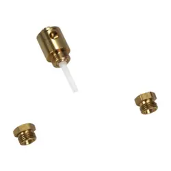
Residue buildup on water nozzle opening.
Unscrew nozzle and clean if necessary.
Check Vent Message on Display During Cycle Operation
Poor airflow.
Check lint screen. Clean if necessary. Check ventilation system. Clean if necessary.
Cannot Connect to Home WIFI System (On Some Models)
HMI Wi-Fi disabled. HMI not connected to Wi-Fi router
Select Remote Enable key. Use App to setup Wi-Fi. See Troubleshooting Guide for Connected Appliance.
TROUBLESHOOTING TESTS
IMPORTANT: The following procedures may require the use of needle probes to measure voltage. Failure to use needle probes will damage the connectors.
TEST #1: Main Control (ACU)
This test is used to determine if power is present at the machine control electronics. This test assumes that proper voltage is present at the outlet.
Verify that the green LED on the ACU is lit when the dryer is turned on. NOTE: It is important to verify that the system is not in “Low Power” mode. If the HMI is working correctly, it will “wake up” the system after powering up and pressing Power. To verify, unplug dryer or disconnect power for 60 seconds. Plug in dryer or reconnect power. Press POWER. If the ACU comes up (i.e., the green LED in the center of the ACU flashes and then stays lit after bootup is complete) but the HMI does not, there may be a problem with the HMI.
Unplug dryer or disconnect power.
Check for appropriate line voltages at the outlet: 240 VAC (electric 2-phase), 208 VAC (electric 3-phase), or 120 VAC (gas).
If line voltage is present, go to step 4.
If line voltage is not present, check for tripped circuit breaker or blown household fuse.
If CB (circuit breaker) is not tripped, have customer check with qualified electrician.
Remove top panel to access the machine electronics
ACU VAC – With voltmeter set to AC, connect black probe to ACU J8-3 (N) and red probe to J9-2 (L1) (see Figure 2).
If 120 VAC is present, unplug dryer or disconnect power and go to step 6.
If 120 VAC is not present, unplug dryer or disconnect power and perform Test #2: Supply Connections.
ACU +5 VDC – With voltmeter set to DC, unplug connector J2 from the ACU and connect black probe to ACU J2-4 (ground) and red probe to J2-2 (+5 VDC). Plug in dryer or reconnect power.
If +5 VDC is present, unplug dryer or disconnect power and go to step 9.
If +5 VDC is not present, go to step 7.
Unplug dryer or disconnect power. Unplug J14 from the ACU. Plug in dryer or reconnect power and repeat step 6.
If +5 VDC returns, one of the thermistors has shorted. To diagnose thermistors, see Test #4a: Thermistors.
If +5 VDC is not present, go to step 8.
Unplug dryer or disconnect power. Reconnect J14 to the ACU and unplug J2 from the ACU. Plug in dryer or reconnect power and repeat step 6. Perform voltage check inside header J2 on ACU, between pins 2 & 4—DO NOT SHORT PINS TOGETHER.
If +5 VDC is still missing, unplug dryer or disconnect power and replace the ACU.
If +5 VDC returns, unplug dryer or disconnect power and check harnesses and connections between the ACU and HMI. If acceptable, replace the HMI.
ACU +12.7 VDC – with voltmeter set to DC, connect black probe to ACU J2-4 (ground) and red probe to J2-1 (+12.7 VDC).
If +12.7 VDC is present, go to step 11.
If +12.7 VDC is not present, go to step 10.
Unplug dryer or disconnect power. Unplug connector J2 from the ACU. Perform voltage check inside header J2 on ACU, between pins 1 & 4—DO NOT SHORT PINS TOGETHER.
If +12.7 VDC is still missing, unplug dryer or disconnect power and replace the ACU.
If +12.7 VDC returns, unplug dryer or disconnect power and check harnesses and connections between the ACU and HMI. If acceptable, replace the HMI.
Unplug dryer or disconnect power.
Reassemble all parts and panels.
TEST #2: Supply Connections
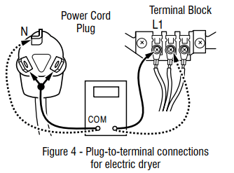
This test assumes that proper voltage is present at the outlet, and for U.S. installations, a visual inspection indicates that the power cord is securely fastened to the terminal block (electric dryer) or wire harness connection (gas dryer).
Unplug dryer or disconnect power.
Remove the cover plate from the top right corner of the back of the dryer. See Figure 3.
With an ohmmeter, check for continuity between the neutral (N) terminal of the plug and the center contact on the terminal block. See figure 4. ➢ If there is no continuity, replace the power cord and test the dryer. ➢ If there is continuity, go to step 4.
In a similar way, check which terminal of the plug is connected to the left-most contact on the terminal block and make a note of it. This will be L1 (black wire) in the wiring diagram. See figure 4.
When this is found, go to step 5.
If neither of the plug terminals have continuity with the left-most contact of the terminal block, replace the power cord and retest dryer.
Access the machine electronics without disconnecting any wiring to the ACU.
With an ohmmeter, check for continuity between the L1 terminal of the plug (found in step 4) and J9-2 (black wire) on the ACU.
If there is continuity, go to step 7.
If there is no continuity, check that wires to the terminal block are mechanically secure. If so, replace the main wire harness and test the dryer.
Check for continuity between the neutral (N) terminal of the plug and J8-3 (white wire) on the ACU.
If there is continuity, go to step 8.
If there is no continuity, and the mechanical connections of the wire are secure, replace the main wire harness.
Visually check that ALL connectors are fully inserted into the ACU.
Visually check that ALL connectors are fully inserted into the HMI.
Reassemble all parts and panels.
Plug in dryer or reconnect power.
Perform steps under “Service Test Mode”, to verify repair.
TEST #3: Motor Circuit
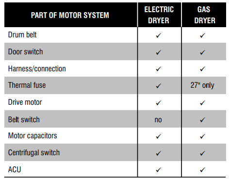
This test will check the wiring to the motor and the motor itself. The following items are part of this motor system:
NOTE: Refer to strip circuit to diagnose drive motor.
Unplug dryer or disconnect power.
Remove console to access the machine electronics. Loosen top and slide back to view drum belt.
Check for loose, worn, or damaged drum belt—repair as necessary.
Door Switch problems can be uncovered by following procedure under Test #7: Door Switch; however, if this was not done, the following can be performed without applying power to the dryer. Connect an ohmmeter across ACU J8-3 (neutral, white wire) and J8-4 (door, tan wire).
With the door properly closed, the ohmmeter should indicate a closed circuit (0–2 Ω).
If not, check harnesses and connections between ACU and door switch. If good, replace the door switch assembly.
Motor Circuit Check - Access the ACU and measure the resistance across J8-4 and J9-1.
If resistance across J8-4 and J9-1 is in the range of 1 to 6 Ω, the motor circuit is acceptable. Replace the ACU.
Otherwise, continue to step 6.
Check the wiring and components in the path between these measurement points by referring to the appropriate wiring diagram (gas or electric). NOTE: To access motor system components, slide the top back and remove the front panel. ALL DRYERS: Continue with step 7 below to test the remaining components in the motor circuit.
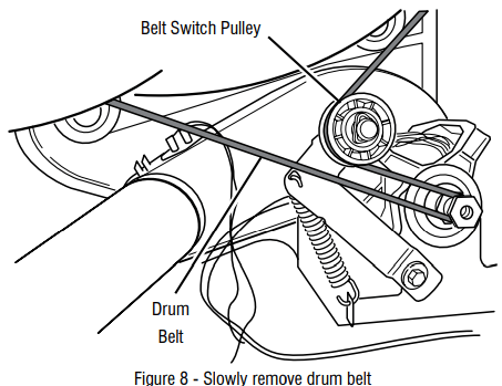
Check the drive motor. Slowly remove the drum belt from the springloaded pulley, gently letting the pulley down. See figure 8.
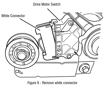
Remove the white connector from the drive motor switch. See figure 9.
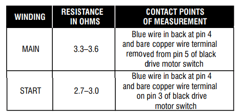
Remove the bare copper wire terminal from pin 5 of black drive motor switch. See figure 10.
Using figure 10 and the strip circuit, check for the resistance values of the motor’s Main and Start winding coils as shown in the following table. NOTE: Main and Start winding coils must be checked at the motor.
If the resistance at the motor is correct, there is an open circuit between the motor and ACU. For gas models, check for a belt switch problem; see step 11. For electric models, check and repair the main wiring harness.
If the Main or Start winding resistance is much greater or less than the values listed in the table above, replace the motor.
On gas dryer only, check the belt switch by unplugging the connector and measuring the resistance between pins 1 and 3 of the belt switch connector while pushing up the pulley (see figure 10).
If the resistance reading goes from open to a few ohms as pulley arm closes the switch, belt switch is good. If not, replace the belt switch.
If belt switch is good and there is still an open circuit, check and repair the main wiring harness.
Reassemble all parts and panels.
Plug in dryer or reconnect power.
Perform steps under “Service Test Mode”, to verify repair.
TEST #4: Heat System
This test is performed when either of the following situations occurs:
Dryer does not heat
Heat will not shut off
This test checks the components making up the heating circuit. The following items are part of this system:
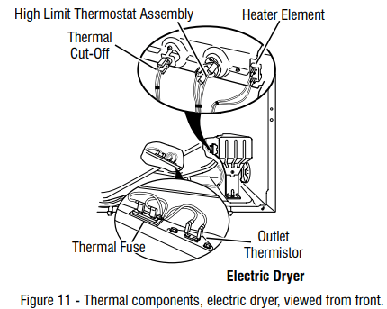
NOTE: On the gas dryer, the inlet thermistor is located at the drum inlet vent. Refer to strip circuit to diagnose heater system.
Dryer does not heat:
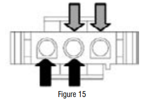
Locate the components using figures 14 and 15. To access heater system components, remove the console, top panel, and front panel.
If L1 is present, the heater relay is receiving L1 line voltage.
If L2 is present, the heater relay is receiving L2 line voltage, confirming that the centrifugal switch, heater, high limit thermostat, and thermal cut-off are functional.
Unplug dryer or disconnect power.
Remove the front panel to access thermal components.
Using an ohmmeter and referring to the strip circuit or wiring diagram, measure the resistance from the red wire terminal at the thermal cut-off to the red wire terminal at the heater.
If the resistance is about 10 Ω, go to step 5.
If an open circuit is detected, go to step 4.
Visually check the wire connections to the thermal cut-off, high limit thermostat, and heater. If the connections look good, check for continuity across each of these components. Refer to strip circuit.
Replace the heater if it is electrically open.
Replace both the thermal cut-off and the high limit thermostat if either the thermal cut-off or the high limit thermostat is electrically open.
If no open circuit is detected, remove the J14 connector from the ACU and measure the outlet thermistor resistance between J14-3 and J14-6 at the connector. Refer to “Outlet Thermistor Resistance” table for temperatures and their associated values.
If the resistance corresponds to the temperature, the outlet thermistor is good. Go to step 6.
If the thermistor resistance does not agree with the table, replace the outlet thermistor.
If the preceding steps did not correct the problem and L1 and L2 were both detected, replace the ACU. If L2 was not detected, suspect the centrifugal switch before replacing the ACU.
Reassemble all parts and panels.
Plug in dryer or reconnect power.
Perform steps under “Service Test Mode”, to verify repair.
Heat will not shut off:
Unplug dryer or disconnect power.
Remove console to access the machine electronics.
Remove connector J14 from the ACU and measure the resistance between J14-3 and J14-6 at the connector. Refer to “Outlet Thermistor Resistance” for temperatures and their associated values.
If the resistance corresponds to the temperature, the outlet thermistor is good.
If the thermistor resistance does not agree with the table, replace the outlet thermistor.
Check heater coil(s) for a short to ground (usually inside the heater box). Repair or replace if necessary.
Plug in dryer or reconnect power.
Run an “AIR” only timed dry cycle (no heat). Check heater relay output on ACU. Unplug dryer or disconnect power. With a voltmeter set to AC, connect voltmeter to terminals 1 & 2 of heater relay. Plug in dryer or reconnect power. Measure the voltage across terminals 1 & 2 of heater relay.
If voltage is present (~240 VAC for electric, ~120 VAC for gas), the relay is open and working normally.
If little or no voltage is present, the relay is closed and heater is activated. Unplug dryer or disconnect power and replace the ACU.
Unplug dryer or disconnect power.
Reassemble all parts and panels.
Plug in dryer or reconnect power.
Perform steps under “Service Test Mode”, to verify repair.
TEST #4a: Thermistors
NOTE: Refer to strip circuit to diagnose outlet and inlet temperature thermistors.
Outlet (Exhaust) Thermistor
The ACU monitors the exhaust temperature using the outlet thermistor, and cycles the heater relay on and off to maintain the desired temperature. NOTE: Begin with an empty dryer and a clean lint screen.
Unplug dryer or disconnect power.
Remove console to access the machine electronics.
Remove connector J14 from the ACU and measure the resistance between J14-3 and J14-6 at the connector. The following table gives temperatures and their associated resistance values. NOTE: All thermistor resistance measurements must be made while dryer is unplugged and connector removed from ACU.
If the resistance is OK, the outlet thermistor is good. Proceed to step 4.
If the thermistor resistance does not agree with the table, replace the outlet thermistor.
Check J14-3 and J14-6 to dryer cabinet ground. If either pin indicates continuity to ground (short), replace wiring harness; otherwise, proceed to step 5. 5. If the preceding steps did not correct the problem, replace the ACU.
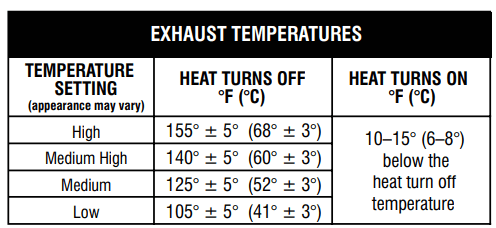
Temperature Levels Incorrect – If no error code is displayed and the connections to the thermistor are good, check the exhaust temperature value at any or all of the temperature levels in question, using the Timed Dry cycle.
IMPORTANT: Be sure EcoBoost or Energy Saver (if available) is turned OFF before testing.
Remove load from dryer and disconnect external vent.
Plug in dryer or reconnect power.
Run a TIMED DRY cycle (Mixed + Timed Dry on Whirlpool models) of at least 2 minutes in duration and select a temperature setting using heat
Using a calibrated temperature probe, take a temperature measurement in the center of the exhaust outlet. The correct exhaust temperatures are as follows:
If the temperature is not reached within ~7 minutes, check voltage level and vent blockage, and then retest.
If the temperature probe does not agree with temperature setting, replace the outlet thermistor.
If the temperature probe confirms the temperature setting, retest at a different temperature setting.
f the preceding steps did not correct the problem, replace the ACU.
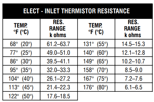
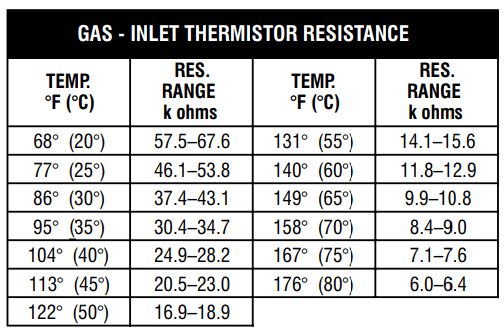
Inlet Thermistor
NOTE: On the electric dryer, the inlet thermistor is part of the high thermostat assembly (see figure 11). On the gas dryer, the inlet thermistor is located at the drum inlet duct (see figure 23).
The ACU monitors the inlet temperature using the inlet thermistor. The inlet thermistor (along with the outlet thermistor) is used to detect air flow, and assists in calculating load size.
Unplug dryer or disconnect power.
Remove console to access the machine electronics.
Remove connector J14 from the ACU and measure the resistance between J14-1 and J14-2 at the connector. The following tables (electric & gas) give temperatures and their associated resistance values.
TEST #4b: Thermal Fuse
The thermal fuse is wired in series with the dryer drive motor.
Unplug dryer or disconnect power.
Slide the top back, remove the front panel, front bulkhead, and drum to access the thermal fuse.
Using an ohmmeter, check the continuity across the thermal fuse. If the ohmmeter indicates an open circuit, replace the thermal fuse.
TEST #4c: Thermal Cut-Off
If the dryer does not produce heat, check the status of the thermal cut-off.
Unplug dryer or disconnect power.
Access the thermal cut-off by removing console, top panel, front panel, front bulkhead, and drum.
Using an ohmmeter, check the continuity across the thermal cut-off. See figures 14 and 15, for location.
If the ohmmeter indicates an open circuit, perform the following:
Replace both the thermal cut-off and high limit thermostat. In addition, check for blocked or improper exhaust system, and, on electric dryers, for heat element malfunction.
TEST #5: Moisture Sensor
This test is performed when an automatic cycle stops too soon, or runs much longer than expected.
NOTE: Dryer will shut down automatically after 2½ hours.
The following items are part of this system:
NOTE: Refer to strip circuit to diagnose moisture sensor.
Activate the Service Diagnostics. See procedures. Run Service Diagnostics/Diagnostics Cycle. Press Right key to advance cycle until display shows Sensing.
Open the door. Using a wet cloth or one finger, jointly touch both sensor strips.
If contact turns off drum light, the moisture sensor passes the test. Go to step 9.
If drum light does not turn off after repeated touching both moisture strips, continue with step 3. NOTE: Overdrying may be caused by a short circuit in the sensor system.
Unplug dryer or disconnect power.
Remove console to access the machine electronics.
Access the moisture sensor wires by sliding the top panel back and removing the front panel. Disconnect the 3-wire moisture sensor connector located below the door opening between the front panel and bulkhead.
Access the ACU and remove connector J13 from the circuit board. Check the wire harness for continuity between J13 and the moisture sensor connector.
If there is continuity, go to step 7.
If there is no continuity, replace the main harness.
Measure the resistance across the outermost contacts of the connector that includes the two MOVs.
If a small resistance is measured, clean the two metal moisture strips inside the drum. If a small resistance is measured after cleaning, replace the sensor harness.
If a small resistance is not measured, go to step 8.
Measure the resistance across each of the outermost contacts and the center terminal (ground connection).
If the moisture sensor diagnostic test passes, check the outlet thermistor: Test #4a: Thermistors.
If the preceding steps did not correct the problem, replace the ACU.
TEST #6: HMI
This test is performed when any of the following situations occurs during the “Key Activation and Encoder Test”.
NOTE: Some models may not have cycle indicator lights and may beep only on the Normal cycle.
None of the indicators or display turn on
Some buttons do not light
No beep sound is heard
None of the indicators or display turn on:
Unplug dryer or disconnect power.
Remove top panel to access the ACU and HMI.
Visually check that ALL ACU connectors are inserted all the way into the ACU.
Remove the fascia and HMI assembly from the console. Visually inspect all connections and reconnect as needed. Reassemble the fascia and HMI assembly to the console.
Visually check that the fascia is properly inserted into the console.
If all visual checks pass, perform Test#1: Main Control (ACU) to verify supply voltages.
If supply voltages are present, replace the HMI and housing assembly.
If supply voltages are not present, replace the ACU.
Reassemble all parts and panels.
Plug in dryer or reconnect power.
Perform the “Service Diagnostic: HMI Test to verify repair.
Some buttons do not light:
Unplug dryer or disconnect power.
Remove top panel to access the ACU and HMI.
Visually check that the HMI and housing assembly is properly inserted into the front console.
If visual check passes, replace the HMI and housing assembly.
Reassemble all parts and panels.
Plug in dryer or reconnect power.
Perform the “Key Activation and Encoder Test” to verify repair.
No beep sound is heard:
Verify that the “Cycle Signal” volume is turned on. Touch the CYCLE SIGNAL button (some models my require press/ hold) to adjust the volume level. Display indicator should show with each selection Off, Low, Medium, High.
Unplug dryer or disconnect power.
Remove top panel to access the ACU and human machine interface (HMI).
Visually check that ALL ACU connectors are inserted all the way into the ACU.
Visually check that ALL HMI connectors are inserted all the way into the HMI.
If all visual checks pass, replace the HMI and housing assembly.
Reassemble all parts and panels.
Plug in dryer or reconnect power.
Perform the “Key Activation and Encoder Test” (see page 5) to verify repair.