ANTI-TIP BRACKET INSTALLATION INSTRUCTIONS
31-10671
04-08 JR
•
•
•
All ranges can tip.
BURNS or other SERIOUS
INJURIES can result.
INSTALL and CHECK the
ANTI-TIP bracket following
the instructions supplied
with the bracket.
WARNING
To reduce the RISK OF TIPPING the range, the range must be
secured by a properly installed ANTI-TIP BRACKET.
Secure the bracket with the screws provided.
NOTE: The installation of the ANTI-TIP bracket must meet all
local codes for securing the appliance.
If you did not receive an anti-tip bracket with your purchase,
call 1-800-626-8774 to receive one at no cost.
In Canada, call 1-800-561-3344.
For installation instructions of the bracket, visit: GEAppliances.com.
In Canada, GEAppliances.ca.
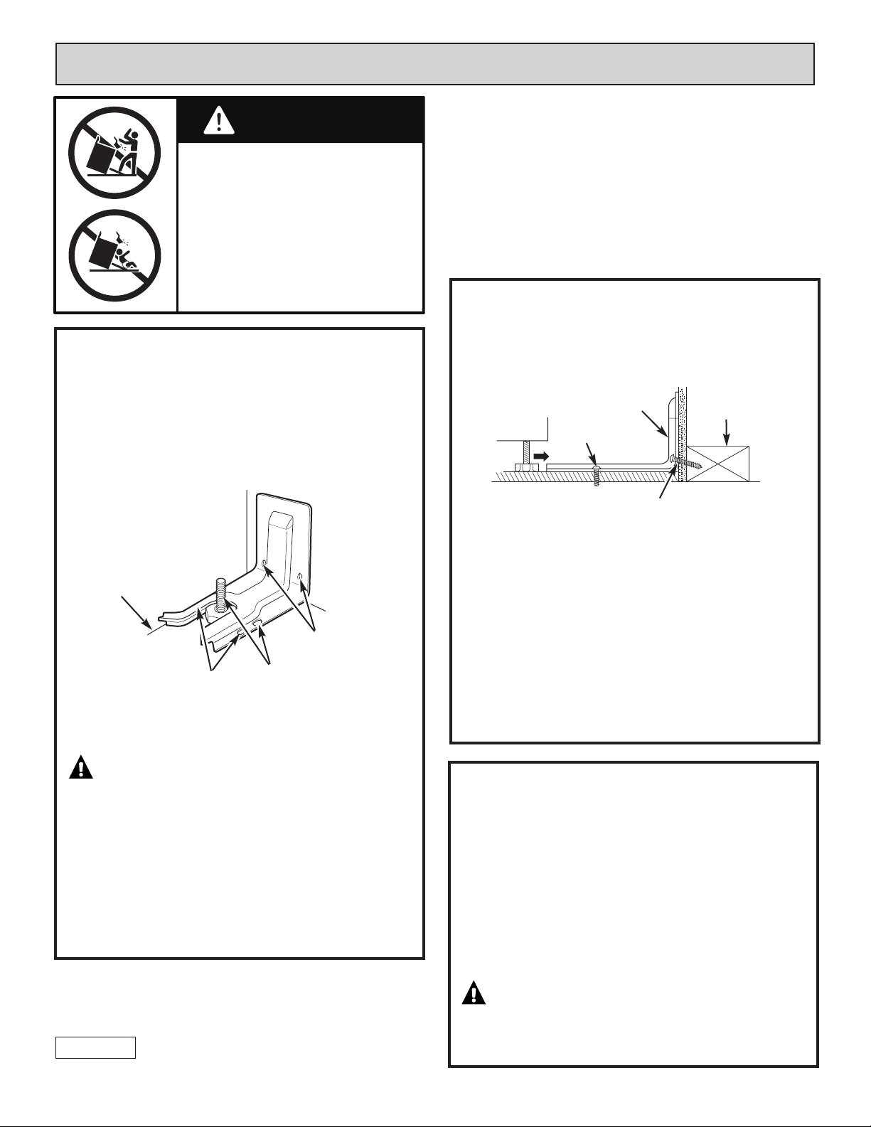
LOCATE THE BRACKET
STEP 1
IMPORTANT: Determine the final location of the range
before attempting to install the bracket.
a. Place the bracket on the floor with the back edge against
the rear wall. If the range does not reach the rear wall,
align the back edge of the bracket with the rear panel of
the range in its final location.
If bracket does not touch the rear wall, you MUST
screw bracket to FLOOR as described in Step 2.
b. Position the side of the bracket against either the left or
right cabinet. If there is no adjacent cabinet, align the
edge of the bracket with the side panel of the range in
its final location. If the countertop overhangs the
cabinet, offset the bracket from the cabinet by the
amount of overhang.
c. Mark the location for the pair of holes to be used (see
illustration above).
NOTE: For FLOOR installation use either Loc A or B. For
REAR WALL installation use Loc C.
SECURE THE BRACKET
STEP 2
The bracket must be screwed to either the FLOOR or REAR
WALL.
FLOOR Installation:
WOOD FLOOR: Use the screws provided to secure the
bracket using the pair of marked holes (either Loc A or B).
CONCRETE FLOOR: Using a concrete bit, drill a 5/32” pilot
hole 2” deep into the concrete at the center of each of the
marked holes (either Loc A or B). Use the screws provided to
secure the bracket into the floor.
REAR WALL Installation:
Use the 2 screws provided to secure the bracket using the
pair of marked holes at Loc C. The screws MUST enter into
a wood sill plate. If the wall contains any metal studs or
similar materials, then the floor must be used.
CHECK THE BRACKET
STEP 3
After installing the bracket, slide the range into its final
location. The rear leveling leg must be fully inserted into the
ANTI-TIP bracket. If the range has a storage drawer, remove
the drawer and look underneath the range to see if the leg
is fully engaged in the bracket as shown in Step 1.
On models without storage drawer or kickpanel, verify the
rear leveling leg is properly secured within the bracket by
carefully tipping the range forward. DO NOT tip the range
more than 4 inches. If the bracket does not stop the range
within 4 inches, the bracket is NOT properly installed and
MUST be reinstalled following these instructions.
The anti-tip bracket must be PROPERLY INSTALLED and
the rear leveling leg must be FULLY ENGAGED into the
bracket to prevent the range from tipping. NEVER
remove the leveling legs. This will prevent the range
from being secured to the ANTI-TIP bracket properly.
Rear Wall
Adjacent cabinet or
final location of range
side panel
Loc A
Loc B
Loc C
Two screws must enter floor
or wall at Loc A, B or C.
Screw must enter
wood or concrete
Attachment to Floor or Rear Wall
Wall Sill Plate
Screw must enter wood
Bracket
INSTRUCCIONES DE INSTALACIÓN DE SOPORTE ANTI-VOLCADURAS
31-10671
04-08 JR
Para reducir el RIESGO DE VOLCAR la cocina, ésta debe sujetarse
mediante un SOPORTE ANTI-VOLCADURAS con una adecuada instalación.
Fije el soporte con los tornillos provistos.
NOTA: La instalación del soporte ANTI-VOLCADURAS debe cumplir
con todos los códigos locales para asegurar el aparato.
Si usted no recibió un soporte anti-volcaduras con su compra, llame al
1-800-626-8774 para recibir uno sin costo alguno.
En Canadá, llame al 1-800-561-3344.
Para instrucciones de instalación del soporte, visite: GEAppliances.com.
En Canadá, GEAppliances.ca.
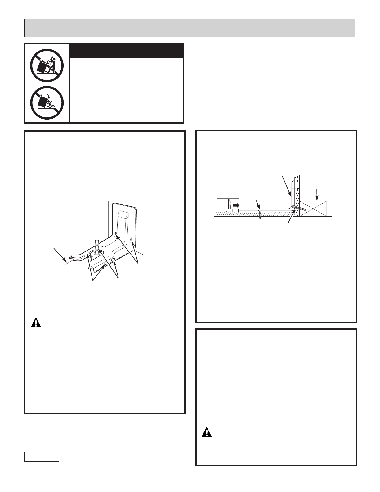
UBIQUE EL SOPORTE
PASO 1
IMPORTANTE: Determine la ubicación final de la cocina
antes de tratar de instalar el soporte.
a. Coloque el soporte en el piso con el lado trasero sobre la
pared trasera. Si la cocina no llega a la pared trasera,
alinee el lado trasero del soporte con el panel trasero de
la cocina en su ubicación final.
Si el soporte no toca la pared trasera, usted DEBE
atornillar el soporte al PISO como se describe en el
Paso 2.
b. Coloque el lado del soporte sobre el gabinete izquierdo o
derecho. Si no hay un gabinete adyacente, alinee el
extremo del soporte con el panel lateral de la cocina en
su ubicación final. Si el mostrador de encimera sobresale
del gabinete, modifique la posición del soporte desde el
gabinete considerando la cantidad que sobresale.
c. Marque la ubicación para el par de orificios que se
utilizarán (ver la ilustración de arriba).
NOTA: Para instalaciones de PISO utilice la Ubic. A o B.
Para la instalación de PARED TRASERA utilice la Ubic. C.
SUJETE EL SOPORTE
PASO 2
El soporte debe atornillarse al PISO o a la PARED TRASERA.
Instalación de PISO:
PISO DE MADERA: Utilice los tornillos provistos para sujetar el
soporte utilizando el par de orificios marcados (Ubic. A o B).
PISO DE CONCRETO: Utilizando una broca para concreto, perfore
un orificio piloto de 5/32” de 2” de profundidad dentro del
concreto en el centro de cada uno de los orificios marcados (Ubic.
A o B). Utilice los tornillos provistos para sujetar el soporte al piso.
Instalación de PARED TRASERA:
Utilice los 2 tornillos provistos para sujetar el soporte utilizando el
par de orificios marcados en Ubic. C. Los tornillos DEBEN ingresar
en el umbral de madera. Si la pared contiene parantes de metal o
materiales similares, entonces debe usarse el piso.
VERIFIQUE EL SOPORTE
PASO 3
Después de instalar el soporte, deslice la cocina a su ubicación final.
La pata de nivelación trasera debe introducirse por completo en el
soporte ANTI-VOLCADURAS. Si la cocina cuenta con el cajón de
almacenamiento, quite el cajón y mire debajo de la cocina para ver
si la pata está bien enganchada en el soporte como puede verse en
el Paso 1.
En modelos sin guanteras ni paneles delanteros inferiores,
v
erifique que la pata de nivelación trasera se encuentre bien
asegurada dentro del soporte inclinando con cuidado la cocina hacia
delante. NO incline la cocina más de 4 pulgadas. Si el soporte no
detiene la cocina dentro de las 4 pulgadas, el soporte NO está bien
instalado y DEBE volver a instalarse siguiendo estas instrucciones.
El soporte anti-volcaduras debe INSTALARSE DE MANERA
CORRECTA y la pata de nivelación trasera debe ENGANCHARSE
BIEN al soporte para evitar que la cocina vuelque. NUNCA quite
las patas de nivelación. Esto no permitirá que la cocina quede
bien sujeta al soporte ANTI-VOLCADURAS.
Pared trasera
Gabinete adyacente o
ubicación final del panel
lateral de la cocina
Ubic. A
Ubic. B
Ubic. C
Dos tornillos deben ingresar
en el piso o pared en la
Ubic. A, B o C.
El tornillo debe
ingresar en madera
o concreto
Sujeción al piso o la pared trasera
Umbral de la pared
El tornillo debe ingresar en madera
Soporte
wADVERTENCIA
• Todas las cocinas pueden volcarse.
• Pueden provocarse QUEMADURAS u
otras LESIONES GRAVES.
• INSTALE y CONTROLE el soporte
ANTI-VOLCADURAS siguiendo las
instrucciones suministradas con
el soporte.