Loading ...
2
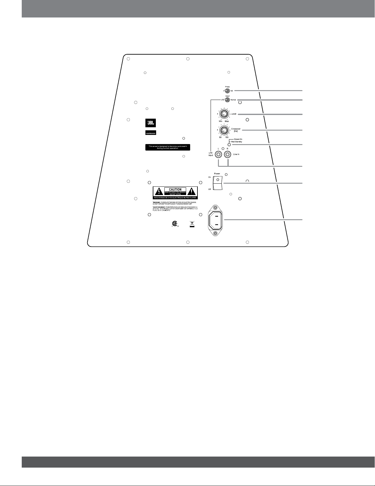
Phase Switch: This switch determines whether the subwoofer transduc-
er's piston-like action moves in and out in phase with the main speakers.
If the subwoofer were to play out of phase with the main speakers, the
sound waves from the main speakers could partially cancel out the sound
waves from the subwoofer, reducing bass performance and sonic impact.
This phenomenon depends in part on the placement of all the speakers
relative to the listening position and to each other in the room.
Input Mode Switch: When this switch is in the “Normal” setting, the input
signal from both Line In connectors is routed through the subwoofer's
built-in low-pass crossover network. When the switch is in the “LFE” set-
ting, the input signal from the LFE Input connector bypasses the subwoof-
er's built-in crossover network.
Volume Control: Use this control to adjust the subwoofer’s volume. Turn
the knob clockwise to increase the volume; turn the knob counterclock-
wise to decrease the volume.
Crossover Control: This control determines the highest frequency at
which the subwoofer reproduces sounds. The higher you set the Cross-
over control, the higher in frequency the subwoofer will operate and the
more its bass will “overlap” that of the satellite speakers. This adjust-
ment helps achieve a smooth transition of bass frequencies between the
subwoofer and the satellites for a variety of different rooms and subwoofer
locations.
NOTE: The Crossover Control functions only when the Input Mode switch
is in the “Normal” setting.
On/Standby LED: When the Power switch is in the “On” position, this
LED indicates whether the subwoofer is in the On or Standby state:
• When the LED glows green, the subwoofer is turned on.
• When the LED glows red, the subwoofer is in the Standby mode.
Line In/LFE Input Connectors:
• When you’re connecting the subwoofer to the dedicated subwoofer
output of a receiver/processor that has its own low-pass crossover
network, use the LFE Input connector and set the Input Mode switch
in the “LFE” position.
• When you're connecting the subwoofer to the preamp or subwoofer
outputs of a receiver/processor that does not have its own low-pass
crossover network, use both Line In connectors and set the Input
Mode switch in the “Normal” position. If your receiver/processor only
has one subwoofer output you can use either Line In connector.
Power Switch: Set this switch in the “On” position to turn the subwoofer
on. The subwoofer will then be in the Standby mode. It will automatically
turn On when an audio signal is detected at its inputs, and will return to the
Standby mode when no audio signal is detected its inputs after approxi-
mately 10 minutes.
If you will be away from home, or will not be using the subwoofer for an
extended period, set this switch in the “Off” position to conserve energy.
Power Cord Connector: After you have made and verified the subwoof-
er’s input connections, plug the female end of the supplied IEC power cord
into the subwoofer’s Power Cord connector, and plug the other end of the
power cord into an active, unswitched electrical outlet for proper opera-
tion of the subwoofer. DO NOT plug the power cord into the accessory
outlets found on some audio components.
suBwooFer rear-Panel controls and connectIons
205323
North rid ge, C A USA
Desig ned a nd en ginee red i n USA
Made in P.R.C
SUB150P
Phase Switch
Input Mode Switch
Volume Control
Crossover Control
On/Standby LED
Power Switch
Line-Level/LFE
Input Connectors
Power Cord
Connector
Loading ...
Loading ...