
Loading ...
Loading ...
Loading ...
Mounting
Holes
Connector
Sot
2"x 4"
Framing
1/2" ick
Drywall
Screw
Hood
Front
OPTIONAL DUCT COVER
1. Install the hood as described in “Hood Rough-In Plate Mount”
Note: Be sure to allow enough room for duct cover width
on the top section of the rough-in plate.
2. Slide Duct Cover into opening.
3. Attach Duct Cover from the inside of the hood through lter
opening using the screws provided. (See gure 7)
Note: Do not completely tighten screws until all components
have been installed. At this point, check the alignment of the
duct to the hood. First tighten the four corners to secure the
duct, then tighten the remaining screws.
Mounting
Screws
Optional
Duct Cover
WALL HOOD INSTALLATION - (continued)
5
Attach the hood to the removable back panel by aligning
the welded studs on the removable back panel with the
slotted holes on the back of the hood. (See Figure 5)
Using the screws provided, secure the hood assembly to
the removable back panel. (See Figure 5)
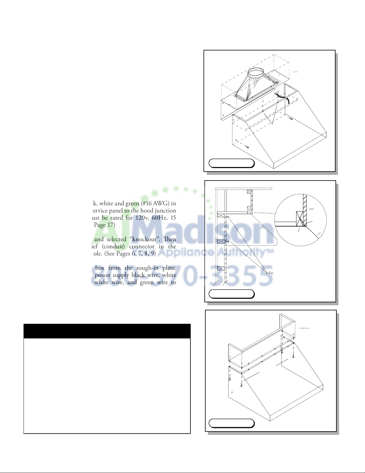
Add 2”x4” wood framing block to aid in securing the top
and rear of the hood to the wall. (See Figure 6)
To mount CFM300, CFM600 and CFM1200 fans
within wall hoods. (See Figures 8, 9, 10, 11) (Page 6-9)
Install the fan by aligning the fan holes with the welded
studs on the removable back panel. Tighten the fan to
the panel using the hex nuts provided. (See Figures 8, 9,
10, 11) (Page 6-9)
Connect the “Molex” from the fan to the “Molex” plug
on the hood. (See Figure 4.) (Page 4)
Attach three wires: black, white and green (#16 AWG) in
1/2” conduit from the service panel to the hood junction
box. Power supply must be rated for 120v, 60Hz, 15
amps (minimum). (See Page 17)
Remove junction box and selected “knockout”. en
install the strain relief (conduit) connector in the
removable back panel hole. (See Pages 6, 7, 8, 9)
Remove the junction box from the rough-in plate.
Connect black wire to power supply black wire, white
wire to power supply white wire, and green wire to
power supply green wire. (See Pages 6, 7, 8, 9)
Place all wiring connectors inside junction box and
reinstall removable back panel.
1.
2.
3.
4.
5.
6.
7.
8.
9.
10.
Finished Lag Screws (4 total)
Figure 5.
Figure 6.
Figure 7.
Loading ...
Loading ...
Loading ...