Loading ...
Loading ...
Loading ...
9
Nº53 Power Amplifier
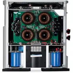
Rear Panel
The Nº53 rear panel, shown on the left, provides power controls
and all of the cable connections for the amplifier.
The rear panel can be broken into four sections:
• Control – includes connections for ML Net, Link2, and triggers,
as well as the Power Save Mode switch.
• Input – provides connections for the audio input.
• Binding Posts – provide connections for the loudspeaker output.
• Power – includes the AC input connector and main power
switch.
Note The audio outputs of this power amplifier are considered Class 2 (CL2)
circuits in North America. This means the wire connected between this
amplifier and the speaker(s) shall be rated at minimum Class 2 (CL2)
and shall be installed according to the U.S. National Electrical Code
(NEC) Article 725 or Canadian Electrical Code (CEC) Section 16.
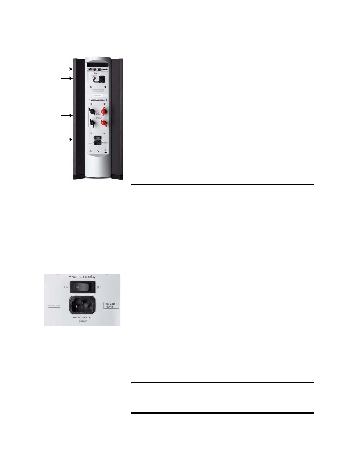
Power
The power section of the rear panel contains the main Power switch
and the AC input connector.
Power Switch (~ AC Mains Relay)
Provides power to the Nº53 internal circuits. When the rear panel
Power switch is used to turn on the Nº53, the amplifier enters either
Standby mode or Power Save mode, depending upon the state of
the rear panel Power Save Mode switch.
AC input (~ AC Mains)
Provides AC power to the Nº53 when the supplied power cord is
connected from the AC input connector on the Nº53 rear panel to
an electrical outlet.
Caution! Before operating the N
o
53, verify that the voltage label near the
AC input connector indicates an operating voltage compatible
with the voltage level of the electrical outlet you intend to use.
Power
Input
Control
Binding
Posts
Loading ...
Loading ...
Loading ...