Loading ...
Loading ...
Loading ...
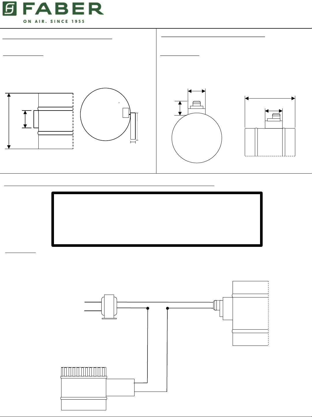
Air Switch Assembly and Collar Specifications:
(located inside range hood ducting)
Unit Specifications:
16 AWG x 2, 10A, 24 VAC. Refer to full safety instructions prior to
installation.
¾”
3 ¼ ”
6”
2”
Motorized Fresh Air Damper Specifications:
(located in fresh air ducting from outside the home)
Air Switch
Assembly
Available in
6” and 10”
Unit Specifications
Weight: 3 lbs.
0.25 amps, 24 VAC, 60 HZ, 7 watts. Shipped in normally
closed position.
8”
2 ¾”
Motorized
Damper
Available in
6” and 10”
2 ¾”
2 5/8”
5
WIRING DIAGRAM for Direct Kitchen Connection (not used for HVAC system connection):
WARNING: TO REDUCE THE RISK OF FIRE, ELECTRICAL SHOCK HAZARD,
OR INJURY TO PERSONS, OBSERVE THE FOLLOWING:
1. Shut off and disconnect all power supply to unit(s) prior to installation or service/repair of device.
2. Use this unit only in manner intended by manufacturer.
3. All applications of device must follow all applicable laws, codes, regulations, and standards.
4. Installation of device must be completed by a certified installation expert or HVAC professional.
5. For residential use only, any use beyond factory recommendations voids all warranties.
Air Switch
Assembly
24 VAC Power
Transformer
Line
Volts
Motorized Fresh
Air Damper
Circuit Setup
1. Using a 24 Volt Class 2 Transformer, Take one Open terminal and Connect to the Motorized Damper.
2. Still Using the 24 Volt Transformer, Take the other Open Terminal and Connect to the Air Switch Assembly.
3. Lastly Take the Second Open Terminal from Switch Assembly and Connect to The Motorized Damper’s other
Open terminal, therefore completing the Circuit.
Loading ...
Loading ...
Loading ...