Loading ...
Loading ...
Loading ...
12
Before installation and usage, read all the instructions and make sure that the
voltage (V) and the frequency (Hz) indicated on the identification plate (found
inside your Cooker Hood) and all the data inside the appliance are exactly the
same as the voltage and frequency in your home.
NOTE: The manufacturer declines all responsibility in the event of failure to observe all the
accident-prevention regulations in force which are necessary for normal use and regular
operation of the electric system.
______________________________________________
ELECTRICAL CONNECTION
Y
Y
o
o
u
u
r
r
c
c
o
o
o
o
k
k
e
e
r
r
h
h
o
o
o
o
d
d
i
i
s
s
i
i
n
n
t
t
e
e
n
n
d
d
e
e
d
d
f
f
o
o
r
r
f
f
i
i
t
t
t
t
e
e
d
d
a
a
n
n
d
d
p
p
e
e
r
r
m
m
a
a
n
n
e
e
n
n
t
t
i
i
n
n
s
s
t
t
a
a
l
l
l
l
a
a
t
t
i
i
o
o
n
n
.
.
o The power cable must be
connected to the terminals
marked L (live) and N (neutral)
in the hood and fixed with a
cable clamp.
o The cooker hood’s power cable
must be fitted upstream from the
electrical connection using an
omni-polar switch with a contact
distance of at least 3mm.
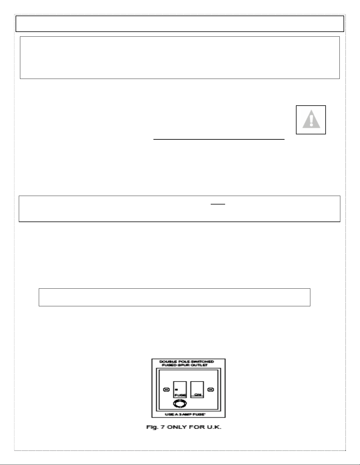
NOTE: (UK only) WARNING – THIS APPLIANCE MUST NOT
BE EARTHED. It should only be
connected by a competent person using fixed wiring via a DOUBLE POLE SWITCHED FUSED
SPUR OUTLET.
We recommend that the appliance is connected by a qualified electrician who is a member
of the N.I.C.E.I.C. and who will comply with the I.E.E. and local regulations. The wires in
the mains lead are coloured in accordance with the following U.K. code:
Blue= Neutral, Brown = Live, Green/Yellow = Ground
If you can only find two wires in the cable (blue and brown), neither must be
connected to the Earth terminal!
• As the colours of the wires in the appliance’s mains lead may not
correspond with the coloured markings identifying the terminals in
your spur box, please proceed as follows:
__________________________________________________________
1) The BLUE WIRE
must be connected
to the terminal
marked ‘N’
(Neutral), or
coloured Black.
2)
The BROWN
WIRE must be
connected to the
terminal marked
‘L’ (‘Live’), or
coloured RED
(Fig. 7 – at left
)
INSTALLATION INSTRUCTIONS - Electrical
Loading ...
Loading ...
Loading ...