Loading ...
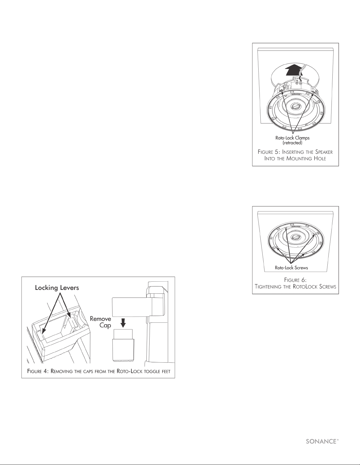
3. Make sure all the
Roto-Lock toggle feet
are retracted so that
they are tucked within
the mounting hole’s
border. Insert the
speaker into the
hole in the ceiling
(Figure 5). The Roto-
Lock system can
accommodate a ceiling
material thickness of
1-1/4” (32mm) with
the toggle foot cap
removed the system can
accommodate a ceiling
material thickness of
1-7/8” (48mm).
4. When installing into
double drywall or other
thicker ceiling materials,
you may need to remove
part of the two-piece
toggle feet. Use a small
screwdriver to gently
release the two locking
levers (Figure 4).
5. Tighten the screws
on the front of the
speaker baffle. The
Roto-Lock toggle feet will
automatically rotate into
position and begin
clamping the speaker
(Figure 6). When you
notice resistance on
the screws the speaker
has been clamped
successfully.
I M P O R T A N T : ALWAYS USE LOW TORQUE SETTINGS;
NEVER OVER-TIGHTEN.
NOTE: ADJUST THE TENSION OF THE ROTO-LOCK CLAMPS SO
THAT THE SPEAKER FRAME IS FLAT. THIS WILL HELP ENSURE THAT
THE GRILLE CONTACTS THE CEILING ALL THE WAY AROUND THE
SPEAKER FOR A PROPER FIT.
6. The micro-trim grille is held in place by several small, powerful
magnets on the speaker frame. Place the grille against the
speaker and the magnets will hold it firmly in place. When
properly installed, the grille trim should make contact with the
wall all the way around the speaker.
Before Installation
1. Determine the location for the speaker (see Speaker Placement
on page 1).
2. Perform an obstruction survey using a stud finder to be certain that
there are no studs, conduit, pipes,heating,ducts, pocket doors or
air returns in the ceiling cavity that will interfere with the speaker.
If you are unsure about obstructions, drill a small hole in the center
of the outline and insert a coat hanger wire into the hole to feel
around for possible obstructions.
3. Cut the mounting hole using a keyhole or drywall saw, and run
the speaker wires from the mounting hole to the amplifier
location.
NOTE: CONSULT LOCAL BUILDING CODES BEFORE RUNNING
SPEAKER WIRES THROUGH CEILINGS.
Installation
Sonance Visual Performance Speakers feature integral
Roto-Lock
®
mounting system for quick mounting directly into
existing ceilings.
1. Strip 1/4” – 1/2” (6mm – 12mm) of insulation from each speaker
lead. Twist the strands or tin the exposed wire with solder to
ensure that there are no stray strands.
NOTE: STRAY STRANDS THAT TOUCH EACH OTHER CAN CAUSE
A SHORT-CIRCUIT THAT CAN DAMAGE THE AMPLIFIER.
2. The speaker’s terminals are spring-loaded. Push the top of
each terminal down to open the connector and insert the
exposed wires into the holes in the spring terminals.
The speaker’s positive spring terminal is labeled with a red dot;
the negative spring terminal is labeled with a black dot. Double-
check that you connected amplifier “+” to speaker “+” and
amplifier “–” to speaker “–”.
VISUAL PERFORMANCE
®
ROUND SPEAKERS
2
Loading ...
Loading ...
Loading ...